Exercise 2-1 Resistance Temperature Detectors (RTDs)
19
2-9 Exercise 2-1 Resistance Temperature Detectors (RTDs) EXERCISE OBJECTIVES • To explain how resistance temperature detectors (RTDs) operate; • To describe the relationship between the temperature and the electrical resistance of the most common types of RTDs; • To define the following terms: nominal resistance, temperature coefficient, and sensitivity. • To explain how a Wheatstone bridge can be used to measure the voltage produced across an RTD. DISCUSSION Electrical resistance An important characteristic of all metals is their electrical resistance. Electrical resistance is the opposition of the metal to the flow of electrical current. Electrical resistance is measured in ohms (Ω) in both the S.I. and U.S. systems of units. The electrical resistance of a metal is dependent upon the temperature at which the metal is. Figure 2-4, for example, shows what happens to the relative resistance of different metals as their temperature increases. The relative resistance is the ratio between the resistance at the applied temperature to the resistance at a reference temperature of 0EC (32EF). As the figure shows, the relative resistance of the metals increases as their temperature gets higher. Moreover, the relative resistance increases almost linearly with temperature, at least over a substantial range of temperatures. Besides, the relative resistance of nickel increases more sharply with temperature than that of copper or platinum.
-
Upload
khangminh22 -
Category
Documents
-
view
6 -
download
0
Transcript of Exercise 2-1 Resistance Temperature Detectors (RTDs)
2-9
Exercise 2-1
Resistance Temperature Detectors (RTDs)
EXERCISE OBJECTIVES
• To explain how resistance temperature detectors (RTDs) operate;• To describe the relationship between the temperature and the electrical
resistance of the most common types of RTDs;• To define the following terms: nominal resistance, temperature coefficient, and
sensitivity.• To explain how a Wheatstone bridge can be used to measure the voltage
produced across an RTD.
DISCUSSION
Electrical resistance
An important characteristic of all metals is their electrical resistance. Electricalresistance is the opposition of the metal to the flow of electrical current. Electricalresistance is measured in ohms (Ω) in both the S.I. and U.S. systems of units.
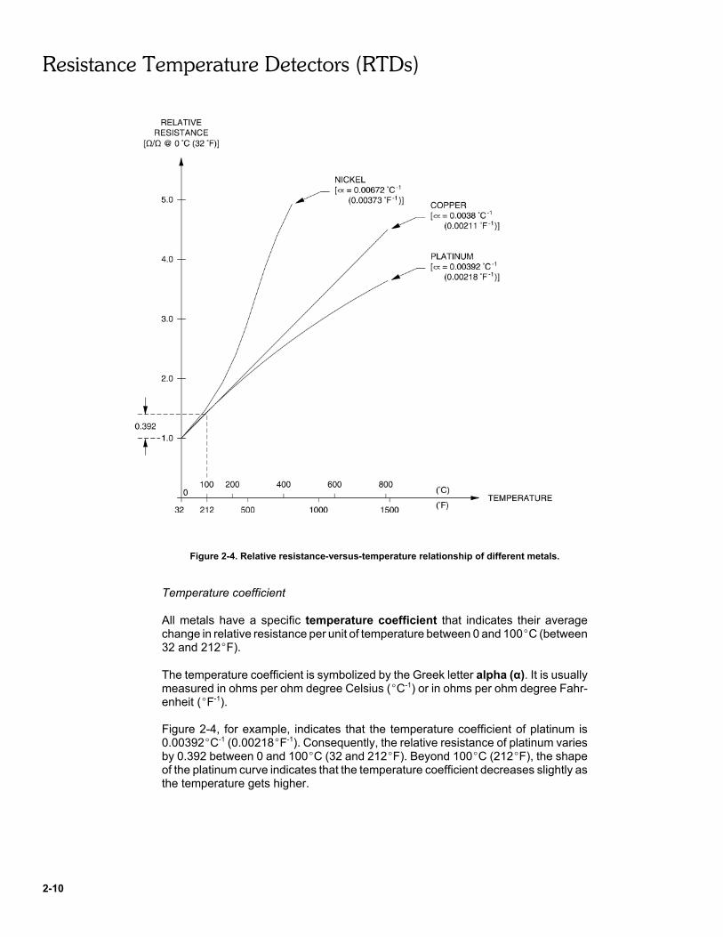
The electrical resistance of a metal is dependent upon the temperature at which themetal is. Figure 2-4, for example, shows what happens to the relative resistance ofdifferent metals as their temperature increases. The relative resistance is the ratiobetween the resistance at the applied temperature to the resistance at a referencetemperature of 0EC (32EF).
As the figure shows, the relative resistance of the metals increases as theirtemperature gets higher. Moreover, the relative resistance increases almost linearlywith temperature, at least over a substantial range of temperatures. Besides, therelative resistance of nickel increases more sharply with temperature than that ofcopper or platinum.
Resistance Temperature Detectors (RTDs)
2-10
Figure 2-4. Relative resistance-versus-temperature relationship of different metals.
Temperature coefficient
All metals have a specific temperature coefficient that indicates their averagechange in relative resistance per unit of temperature between 0 and 100EC (between32 and 212EF).
The temperature coefficient is symbolized by the Greek letter alpha (α). It is usuallymeasured in ohms per ohm degree Celsius (EC-1) or in ohms per ohm degree Fahr-enheit (EF-1).
Figure 2-4, for example, indicates that the temperature coefficient of platinum is0.00392EC-1 (0.00218EF-1). Consequently, the relative resistance of platinum variesby 0.392 between 0 and 100EC (32 and 212EF). Beyond 100EC (212EF), the shapeof the platinum curve indicates that the temperature coefficient decreases slightly asthe temperature gets higher.
Resistance Temperature Detectors (RTDs)
2-11
Resistance temperature detectors
A resistance temperature detector (RTD) is a primary element that is used to sensetemperature. The RTD works on the principle that the electrical resistance of metalschanges with temperature.
The RTD consists of a metallic conductor usually wound into a coil. The RTD is tobe connected to an electrical circuit in order to make a constant excitation currentflow through it. As the temperature increases, the electrical resistance of the metallicconductor increases and, therefore, the voltage across the RTD increases.
Consequently, by measuring the voltage across the RTD, a signal proportional to thetemperature of the RTD can be obtained. This signal can be conditioned into acurrent, voltage, or pressure of normalized range that is suitable for instrumentationand control, the combination of the RTD and the conditioning circuit thus forming atemperature transmitter.
RTD metals
The selection of a metal for use as an RTD depends on several factors. Amongthese, the most important are the capability to follow rapidly changing temperatures,a good linearity, a good reproducibility, and a relatively high change of resistance fora given change in temperature (i.e. a high temperature coefficient).
The metals most commonly used for RTDs are platinum, nickel, and copper (referto Figure 2-4):
• Platinum is the preferred metal for RTDs. It has been chosen as the internationalstandard metal for RTD temperature measurement. Platinum has a nearly linearresistance-versus-temperature relationship over a wide temperature range.Platinum offers good stability and reproducibility. It is well-suited for themeasurement of high temperatures up to 650EC (1200EF).
• Nickel is the second mostly used metal for RTDs. It is less expensive thanplatinum and it is more sensitive because of its higher temperature coefficient.However, nickel has a narrower sensing range than platinum and is limited to themeasurement of temperatures below 300EC (570EF).
• Copper is the least expensive of the three metals and it has the most linearrelationship. Similar to platinum, copper is well suited for the measurement ofhigh temperatures. However, copper is subject to oxidation, and it has poorerstability and reproducibility than platinum.
RTD characteristics
Two important characteristics of RTDs are their nominal resistance and theirtemperature coefficient:
• The nominal resistance is the resistance of the RTD at a given referencetemperature, as specified by the manufacturer. Platinum RTDs, for example, areusually designed so that their nominal resistance is 100 Ω at the ice referencepoint of 0EC (32EF).
Resistance Temperature Detectors (RTDs)
2-12
• The temperature coefficient is the mean change in relative resistance of themetal per unit of temperature between 0 and 100EC (32 and 212EF), aspreviously explained.
The nominal resistance and the temperature coefficient of an RTD determine thesensitivity of the RTD within the 0-100EC (32-212EF) temperature range. Thesensitivity is the amount by which the resistance of the RTD will change per unit oftemperature, in Ω/EC (or Ω/EF).
For example, a platinum RTD having a nominal resistance of 100 Ω at 0EC (32EF)and a temperature coefficient of 0.00392EC-1 (0.00218EF-1) will have a sensitivity of0.392 Ω/EC (0.218 Ω/EF) within the 0-100EC (32-212EF) temperature range.
Measurement of the voltage across an RTD
As previously mentioned, the voltage produced across an RTD, which is directlyproportional to temperature, can be used for process instrumentation and control.
The traditional method of measuring the voltage across an RTD is to use aWheatstone bridge, as Figure 2-5 (a) shows.
• The RTD and its two lead wires constitute one leg of the bridge. Resistors R1 andR2 are of equal resistance, while resistor R3 is adjustable and is used as areference.
• A DC voltage source supplies an excitation current to the RTD.
• A differential amplifier produces a voltage VO proportional to the bridge outputvoltage (measured between points a and b).
With the RTD placed in an ice bath at 0EC (32EF), resistor R3 is initially adjusted inorder to obtain a null voltage (0 V) at the output of the differential amplifier. In thiscondition, the bridge is said to be null balanced.
Once the bridge has been null balanced, the amplifier output voltage will vary indirect proportion to the temperature of the RTD.

Resistance Temperature Detectors (RTDs)
2-13
Figure 2-5. Measurement of the voltage across an RTD.
If the two leads that connect the RTD to the bridge are more than a few centimeters(inches) long, they will introduce an error in the temperature measurement. Thisoccurs because the resistance of the leads will contribute to the voltage producedat the output of the bridge, causing the measured temperature to be higher than thatactually measured.
To minimize this error, RTDs are available in a three-wire version. The extra wire isused to cancel the resistances of lead wires 1 and 2 by balancing the bridge, asFigure 2-5 (b) shows. This has the effect of removing the error produced by leadwires 1 and 2 as long as these wires are of equal resistance (i.e. of equal length andtemperature).
Advantages and limitations of RTDs
RTDs have the following advantages: they provide a good sensitivity, a goodreproducibility, and a good stability. They also provide a high accuracy, someplatinum RTDs being able to measure a few thousandths of a degree.
However, RTDs are relatively expensive, and they have a slower response time thanthermocouples. Moreover, the measurement accuracy of RTDs is dependent uponthe thermal stability of the resistors and power supply used in the Wheatstonebridge.
The RTD probe and the RTD Temperature Transmitter of the Process ControlTraining System
The Process Control Training System comes with a three-wire RTD probe that usesa platinum RTD of 100 Ω at 0EC (32EF). The RTD probe is intended to be used withthe RTD Temperature Transmitter to measure the temperature of the water in thetrainer Column, as Figure 2-6 shows.

Resistance Temperature Detectors (RTDs)
2-14
The tip of the RTD probe, which contains the RTD, is to be inserted into the Columnthrough the opening of the Float Switch. The other end of the RTD probe, which hasthree leads, is to be connected to the "100-Ω RTD" terminals of the RTDTemperature Transmitter.
The RTD Temperature Transmitter produces an excitation current through the RTDand it measures the resulting voltage produced across the RTD. This voltage, whichis proportional to the temperature of the RTD, is conditioned into normalized voltagesand current that are available at the transmitter OUTPUTS.
The transmitter also contains a calibration source that can be used to simulate thevoltage produced across the RTD for any RTD temperature comprised between 0and 100EC (32 and 212EF). The source eliminates the need to set the RTD at a well-known temperature when performing calibration of the transmitter OUTPUTS.
The following is a detailed description of the RTD Temperature Transmitter terminalsand adjustments (refer to Figure 2-6):
Î POWER INPUT terminals: used to power the transmitter with a DC voltage of24 V.
Ï CALIBRATION SOURCE adjustment knob: sets the probe temperature to besimulated by the calibration source signal. This temperature can be adjustedbetween 0 and 100EC (32 and 212EF).
Ð INPUT SELECTOR: selects between the actual probe signal or the simulatedprobe signal produced by the calibration source.
Ñ CALIBRATION SELECTOR switch: places the 0-5 V and 4-20 mA OUTPUTSin either fixed or variable calibration mode.
Ò ZERO and SPAN adjustment knobs: used in the variable calibration mode(CALIBRATION SELECTOR switch at VARIABLE) to set the temperaturerange for which the 0-5 V and 4-20 mA OUTPUTS will pass from minimum tomaximum:
– The ZERO knob sets the temperature for which the outputs will beminimum (0 V and 4 mA), i.e. the minimum temperature to bedetected. The minimum temperature can be adjusted between 0 and50EC (32 and 122EF).
– The SPAN knob sets the temperature for which the outputs will bemaximum (5 V and 20 mA), i.e. the maximum temperature to bedetected. The maximum temperature can be adjusted between 15 and30EC (27 and 54EF) above the minimum temperature set by the ZEROknob.
Resistance Temperature Detectors (RTDs)
2-15
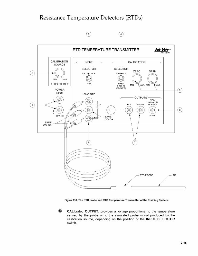
Figure 2-6. The RTD probe and RTD Temperature Transmitter of the Training System.
Ó CALibrated OUTPUT: provides a voltage proportional to the temperaturesensed by the probe or to the simulated probe signal produced by thecalibration source, depending on the position of the INPUT SELECTORswitch.

Resistance Temperature Detectors (RTDs)
2-16
This output has a fixed calibration of 100 mV per sensed EC above 0EC (or56 mV per sensed EF above 32EF). It will pass from 0 to 10 V when theactual or simulated temperature changes from 0 to 100EC (32 to 212EF).
Ô 0-5 V and 4-20 mA OUTPUTS terminals: provide a voltage and a currentproportional to the temperature sensed by the probe or to the probetemperature signal simulated by the calibration source, depending on theposition of the INPUT SELECTOR switch.
The calibration of the 0-5 V and 4-20 mA OUTPUTS can be either fixed orvariable, depending on the position of the CALIBRATION SELECTORswitch:
– In the fixed calibration mode (CALIBRATION SELECTOR switch atFIXED), the temperature range for which the outputs will pass fromminimum to maximum is fixed and is 0-100EC (32-212EF).
– In the variable calibration mode (CALIBRATION SELECTOR switch atVARIABLE), the temperature range for which the outputs will pass fromminimum to maximum can be adjusted by means of the ZERO andSPAN adjustment knobs.
Õ 100-Ω RTD input terminals: used to connect the RTD probe to the transmitter.
Procedure summary
In the first part of the exercise, you will familiarize yourself with the operation of anRTD Temperature Transmitter in the fixed calibration mode.
In the second part of the exercise, you will familiarize yourself with the operation ofan RTD Temperature Transmitter in the variable calibration mode.
In the third part of the exercise, you will set up and operate a temperature process.You will use an RTD Temperature Transmitter to measure the temperature of thewater in a column.
EQUIPMENT REQUIRED
Refer to the Equipment Utilization Chart in Appendix A of the manual to obtain thelist of equipment required to perform this exercise.
PROCEDURE
Operation of the RTD Temperature Transmitter in the fixed calibration mode
G 1. Get the RTD Temperature Transmitter and 24-V DC Power Supply fromyour storage area. Mount these components on the Main Work Surface.
Resistance Temperature Detectors (RTDs)
2-17
G 2. Power up the RTD Temperature Transmitter.
G 3. Get the RTD probe from your storage location and connect it to the100-Ω RTD input of the RTD Temperature Transmitter.
Let the probe tip lie on the Work Surface.
G 4. Make the following settings on the RTD Temperature Transmitter:
INPUT SELECTOR . . . . . . . . . . . . . . . . . . . . . . . . . . . . . . . . . . . RTDCALIBRATION SELECTOR . . . . . . . . . . . . . . . . . . . . . . . . . . FIXED
This selects the RTD probe signal as the transmitter input signal and placesthe transmitter OUTPUTS in the fixed calibration mode.
G 5. Connect a DC voltmeter to the 0-5 V OUTPUT of the RTD TemperatureTransmitter.
Since this output is in the fixed calibration mode, it generates a fixed voltageof 50 mV per sensed EC above 0EC (or 28 mV per sensed EF above 32EF).
According to the voltmeter reading, what is the ambient temperature?
G 6. Further experiment with the operation of the transmitter in the fixedcalibration mode:
– Fill a suitable container with ice water (a mixture of ice cubes andwater).
– Immerse the tip of the RTD probe into the ice water. The 0-5 VOUTPUT voltage should decrease and stabilize at about 0.0 V, which,in the fixed calibration mode, corresponds to an RTD temperature of0EC (32EF).
– Fill a suitable container with boiling water heated by an electric kettle ora microwave oven.
– Immerse the tip of the RTD probe into the boiling water. The 0-5 VOUTPUT voltage should increase and stabilize at about 5.0 V, which,in the fixed calibration mode, corresponds to an RTD temperature of100EC (212EF).
Note: The 0-5 V OUTPUT of the RTD Temperature Transmitterwill stabilize at a voltage lower than 5.0 V if the atmosphericpressure is lower than 101.3 kPa, absolute (14.7 psia).

Resistance Temperature Detectors (RTDs)
2-18
Record below your observations.
Operation of the RTD Temperature Transmitter in the variable calibration mode
Note: In the following steps, you will use the calibration sourceof the RTD Temperature Transmitter to calibrate its 0-5 VOUTPUT so that the voltage at this output passes from 0.0 to5.00 V when the probe temperature simulated by the calibrationsource passes from 25 to 55EC (77 to 131EF), respectively.
G 7. Make the following settings on the RTD Temperature Transmitter:
INPUT SELECTOR . . . . . . . . . . . . . . . . . . . . . . . . . . CAL. SOURCECALIBRATION SELECTOR . . . . . . . . . . . . . . . . . . . . . . . VARIABLEZERO adjustment knob . . . . . . . . . . . . . . . . . . . . . . . . . . . . . . . MAX.SPAN adjustment knob . . . . . . . . . . . . . . . . . . . . . . . . . . . . . . . MAX.
This selects the calibration source signal as the transmitter input signal andplaces the transmitter OUTPUTS in the variable calibration mode.
G 8. Set the probe temperature to be simulated by the calibration source of thetransmitter at 25EC (77EF).
To do so, adjust the CALIBRATION SOURCE knob of the transmitter untilyou obtain a voltage of 2.5 V at the CAL. OUTPUT of the transmitter.
G 9. While monitoring the voltage at the 0-5 V OUTPUT of the transmitter, turnthe ZERO adjustment knob counterclockwise and stop turning it as soon asthe voltage ceases to decrease, which should occur around 0.01 V. Thenvery slowly turn the knob in the clockwise direction and stop turning it assoon as the voltage starts to increase.
This sets the minimum temperature to be detected at 25EC (77EF)approximately.
G 10. Now set the probe temperature to be simulated by the calibration source ofthe transmitter at 55EC (131EF).
To do so, adjust the CALIBRATION SOURCE knob of the transmitter untilyou obtain a voltage of 5.5 V at the CAL. OUTPUT of the transmitter.
G 11. Adjust the SPAN knob in order to obtain a voltage of 5.00 V at thetransmitter 0-5 V OUTPUT.

Resistance Temperature Detectors (RTDs)
2-19
This sets the maximum temperature to be detected at 55EC (131EF)approximately.
G 12. Now that the RTD Temperature Transmitter is calibrated, proceed to thenext part of the exercise.
Measuring temperature with an RTD
Preliminary setup
G 13. Get the Expanding Work Surface from your storage location and mount itvertically (at an angle of 90E) to the Main Work Surface, if this has notalready been done.
G 14. Connect the system shown in Figure 2-7, being careful not to modify thecalibration settings just made on the RTD Temperature Transmitter.Figure 2-8 shows the suggested setup.
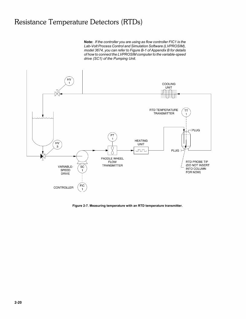
The speed of the variable-speed drive of the Pumping Unit will be controlledwith a controller, FIC1, placed in the manual (open-loop) mode. The Heatingand Cooling Units will be controlled manually. (This is the reason why thereis no temperature controller, or "TC" instrumentation symbol illustrated nextto these units in the flow diagram of Figure 2-7.)
The Column will first be operated in the pressurized mode in order to purgeair from the components downstream of the Column. Consequently, let thetip of the RTD probe lie on the Work Surface for now.
Note: Make sure to mount the Heating Unit at the highestpossible location on the Expanding Work Surface, in order for thisunit to be above the other process components, as Figure 2-8shows. Failure to do so may result in water entering the HeatingUnit upon disconnection of the hoses, which in turn might causedamage to the Heating Unit.
Moreover, mount the 24-V DC Power Supply and the RTDTemperature Transmitter in such a manner that water cannotenter these components and their electrical terminals when hosesare disconnected.
The Heating Unit must be connected for the direction of flowindicated by the arrow heads in the symbol on its front panel.
On the other hand, the Cooling Unit will operate regardless of thedirection of water flow through it. However, to minimize the risk ofcavitation caused by air suction within the pump when the waterbecomes hot, connect the Cooling Unit as indicated in Figure 2-8,that is, with the upper unit port used as the hot water inlet and thelower unit port used as the cooled water outlet. For the samereason, mount the Column at the highest possible location on theExpanding Work Surface in order to create a substantial head ofwater upstream of the Cooling Unit.
Resistance Temperature Detectors (RTDs)
2-20
Note: If the controller you are using as flow controller FIC1 is theLab-Volt Process Control and Simulation Software (LVPROSIM),model 3674, you can refer to Figure B-1 of Appendix B for detailsof how to connect the LVPROSIM computer to the variable-speeddrive (SC1) of the Pumping Unit.
Figure 2-7. Measuring temperature with an RTD temperature transmitter.

Resistance Temperature Detectors (RTDs)
2-21
Figure 2-8. Suggested setup for the diagram of Figure 2-7 (see table next page for the detail of thecomponents).

Resistance Temperature Detectors (RTDs)
2-22
Î : Column Ò : Cooling Unit
Ï : Heating Unit Ó : RTD probe
Ð : Paddle Wheel Flow Transmitter Ô : RTD Temperature Transmitter
Ñ : Pumping Unit Õ : DC Power Supply
G 15. Make the following settings
On the Heating Unit:
S1 switch . . . . . . . . . . . . . . . . . . . . . . . . . . . . . . . . . . . . . . . . . . 2Manual control knob . . . . . . . . . . . . turned fully counterclockwise
On the Cooling Unit:
S1 switch . . . . . . . . . . . . . . . . . . . . . . . . . . . . . . . . . . . . . . . . . . 2Manual control knob . . . . . . . . . . . . turned fully counterclockwiseS2 switch . . . . . . . . . . . . . . . . . . . . . . . . . . . . . . . . . . . . . . . . . .
On the RTD Temperature Transmitter:
SELECTOR switch . . . . . . . . . . . . . . . . . . . . . . . . . . . . . . . . RTD
Note: The 0-5 V OUTPUT of the RTD Temperature Transmittershould still be calibrated for a temperature measurement range of25-55EC (77-131EF) from the first part of the exercise.
G 16. Power up the Heating Unit:
– Connect the AC line cord of this unit to a wall outlet.– Set the POWER switch at I.
G 17. Power up the Cooling Unit and the Paddle Wheel Flow Transmitter byconnecting their POWER INPUT terminals to the 24-V DC Power Supply.
Purging air from the components downstream of the Column
G 18. Make sure flow controller FIC1 is in the manual (open-loop) mode. Set theoutput of this controller at 0% (0 V).
G 19. On the Column, make sure the cap of the insertion opening of the FloatSwitch is tightened firmly.
Resistance Temperature Detectors (RTDs)
2-23
G 20. Make sure the reservoir of the Pumping Unit is filled with about 12 liters(3.2 gallons US) of water. Make sure the baffle plate is properly installed atthe bottom of the reservoir.
G 21. Turn on the Pumping Unit by setting its POWER switch at I.
G 22. On the Pumping Unit, adjust valves HV1 through HV3 as follows:
– Open HV1 completely;– Close HV2 completely;– Set HV3 for directing the full reservoir flow to the pump inlet (turn handle
fully clockwise).
G 23. Set the variable-speed drive of the Pumping Unit to the maximum speed:with controller FIC1 in the manual (open-loop) mode, set the controlleroutput at 100% (5 V).
G 24. Allow the level of the water to rise in the pressurized Column until itstabilizes at some intermediate level. This will force air out of thecomponents downstream of the Column.
Note: If the cap of the insertion opening of the Float Switch onthe Column has not been tightened firmly, air will be allowed toescape from the Column and the water level will not stabilize inthe Column. Should this case occur, stop the variable-speed driveof the Pumping Unit. Open valves HV1 and HV2 of the PumpingUnit in order to drain the Column to the reservoir. When theColumn is empty, tighten the cap of the insertion opening of theFloat Switch on the Column with more force. Then resume theprocedure from step 22.
Placing the system in the water recirculating mode
Note: In the following steps, you will place the system in thewater recirculating mode by setting the Pumping Unit valves so asto direct the return flow directly to the pump inlet, not to thereservoir. This will reduce the time required to raise or decreasethe temperature of the process water. For the same reason, thewater level in the Column will be set at a low, minimum level of7.5 cm (3 in).
G 25. On the Pumping Unit, close valve HV1, which will cause the water level torise further in the Column. Then set valve HV3 for directing the full returnflow directly to the pump inlet (turn handle fully counterclockwise).
G 26. On the Column, remove the cap of the insertion opening of the Float Switchto depressurize the Column. (The water level in the Column will remainstable).

Resistance Temperature Detectors (RTDs)
2-24
G 27. On the Pumping Unit, open valve HV2 in order to decrease the water levelin the Column to 7.5 cm (3 in), then close this valve.
G 28. Readjust the output of controller FIC1 until you read 4.0 V approximately atthe "F (cal.)" output of the Paddle Wheel Flow Transmitter. This will set theflow rate at about 4 l/min (1.1 gal US/min).
Note: Small, continuous variations of a few tenths of volts aroundthe adjusted mean value of 4.0 V are normal at the flowtransmitter output.
However, large variations of one volt or more are abnormal, andindicate that air has entered the system through an untightconnector or component on the suction side of the pump.
Should that case occur, stop the variable-speed drive of thePumping Unit in order to drain the column to the reservoir. Whenthe Column is empty, check the inside of the connector on thePumping Unit return line hose for any dirt or particles. Also, checkthe o-rings on the two hose connectors of the Cooling Unit for anyfissure or crack. Once you have located and eliminated the causeof the leak, reconnect the system as in Figure 2-7 and resume theprocedure from step 19.
Measuring temperature with the RTD
G 29. Insert the RTD probe all the way into the Column in order for its tip to besubmerged in the water.
G 30. Have the signal at the 0-5 V OUTPUT of the RTD Temperature Transmitterplotted on the trend recorder of controller FIC1.
Adjust the update rate of the trend recorder (sampling interval) in order tobe able to monitor the transmitter signal over a period of 10 minutesapproximately.
Note: If the controller you are using as controller FIC1 is the Lab-Volt Process Control and Simulation Software (LVPROSIM),model 3674, refer to Figure B-5 of Appendix B for details of howto connect the LVPROSIM computer to the RTD TemperatureTransmitter. On the I/O Interface, make sure the RANGE switchof ANALOG INPUT 1 is set at 5 V.
In LVPROSIM, select Analog Input 1 from the Trend Recorderselection list to have the RTD Temperature Transmitter signalplotted on the trend recorder. Set the LVPROSIM samplinginterval at 1500 ms. Access the Configure Analog Inputs windowand set the minimum and maximum range values of AnalogInput 1 at 25 and 55EC (77 and 131EF), respectively, whichcorresponds to the current measurement range of the RTDTemperature Transmitter. Set the filter time constant of this inputat 0.5 second. Make sure the square root extracting function isunselected. Accept setup and return to main screen.
Resistance Temperature Detectors (RTDs)
2-25
G 31. On the trend recorder, observe the RTD Temperature Transmitter outputsignal.
Since no electrical power is applied to the heating element of the HeatingUnit, theoretically, the water in the Column should be at ambienttemperature.
Assuming that the ambient temperature is below 25EC (77EF), the level ofthe RTD Temperature Transmitter signal should be at 0% of span on thetrend recorder, since the minimum temperature the transmitter can detecthas been adjusted to 25EC (77EF).
Yet, you may observe that the RTD Temperature Transmitter signal is atsome higher level, thermal energy being transferred to the recirculatedwater mainly from frictional resistance of the pump internal parts.
G 32. On the Heating Unit, set the manual control knob to the mid position. On thetrend recorder, observe what happens to the temperature of the water in theColumn.
Now that electrical power is applied to the heating element of the HeatingUnit, thermal energy is transferred from this element to the recirculatedwater.
Consequently, the temperature of the water should increase in the Column.Is this your observation?
G Yes G No
G 33. Let the temperature of the water in the Column increase to about 45EC(113EF), or 67% of span, then turn the manual control knob of the HeatingUnit fully counterclockwise to remove electrical power from its heatingelement.
According to the RTD Temperature Transmitter output signal on the trendrecorder, did the temperature of the water in the Column increase linearlyover time?
How long did it take for the temperature to increase from the initialtemperature to the final temperature of 45EC (113EF)?
G 34. On the Cooling Unit, turn the manual control knob fully counterclockwise.What happens to the temperature of the water in the Column?
Resistance Temperature Detectors (RTDs)
2-26
G 35. Allow the temperature of the water in the Column to cool down.
According to the RTD Temperature Transmitter output signal, does thetemperature of the water in the Column decrease linearly over time?Explain.
G 36. Stop the variable-speed drive of the Pumping Unit by setting the output ofcontroller FIC1 at 0%.
G 37. Turn off the Pumping Unit, the Heating Unit, and the 24-V DC Power Supplyby setting their POWER switch at O.
G 38. Open valve HV1 of the Pumping Unit completely and let the water in theColumn drain back to the reservoir. The Column can also be drained bydisconnecting the end of the hose connected to the Cooling Unit inlet portand reconnecting it to either of the auxiliary return ports on the PumpingUnit.
G 39. Disconnect the system. Return all leads, hoses, and components to theirstorage location.
CAUTION!
Hot water may remain in the hoses and components. Becareful not to allow water to enter the electrical componentsand their terminals upon disconnection of the hoses.
G 40. Wipe off any water from the floor and the Process Control Training System.
CONCLUSION
In this exercise, you familiarized yourself with the operation of an RTD temperaturetransmitter in the fixed and variable calibration modes. You learned that, in the fixedcalibration mode, the temperature measurement range is fixed and is equal to 0-100EC (32-212EF). In the variable calibration mode, the temperature measurementrange can be adjusted, and a maximum span of 30EC (54EF) can be obtained. Sincethis span is narrower than the 100EC (180EF) span of the fixed calibration mode, thevariable calibration mode provides a greater measurement accuracy for any giventransmitter output range.

Resistance Temperature Detectors (RTDs)
2-27
REVIEW QUESTIONS
1. What is an RTD? How does an RTD work?
2. What are three metals commonly used for RTDs? What are the advantages andlimitations of each metal?
3. Name and describe two important characteristics of RTDs.
4. How is the voltage produced across an RTD traditionally measured?
5. Why are RTDs available in three-wire version? Explain.