
PHOTOVOLTAIC SYSTEM FOR NEXTGRID PARTNERS
7
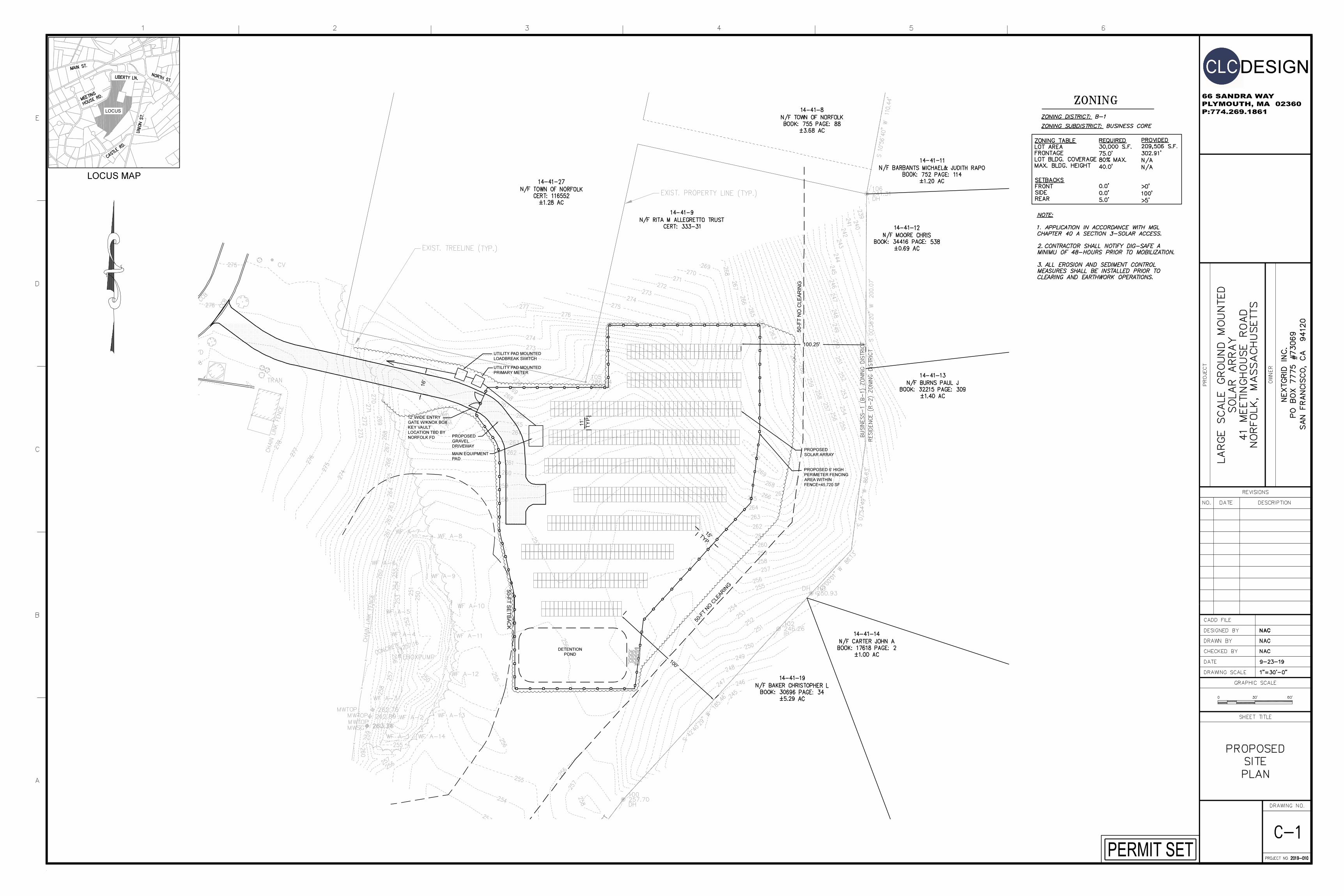
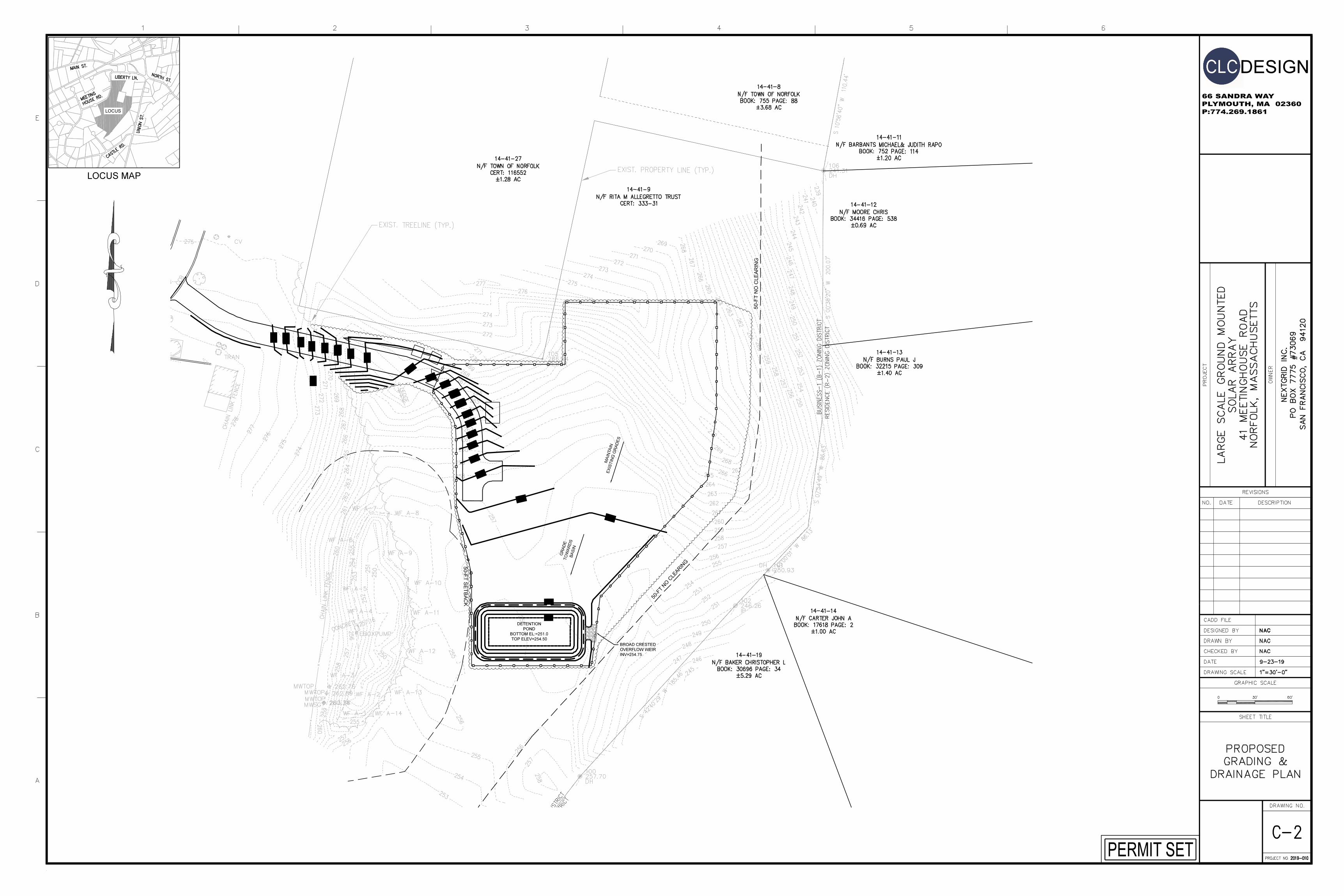
solar design associates inc HARVARD, MA 01451-0242 tel: 978-456-6855 fax: 978-772-9715 www.solardesign.com NEXTGRID PARTNERS - NORFOLK REVISION NOTES MARK DATE DESCRIPTION PROFESSIONAL STAMP THIS DRAWING IS FOR INFORMATION PURPOSES ONLY. CERTIFICATION OR VALIDATION IS TO BE DONE BY A PROFESSIONAL WITH EXPERTISE IN THE REQUIRED FIELD AND A LICENSE IN THE STATE THAT THE INSTALLATION WILL RESIDE. CERTFICIATION OR VALIDATION TO BE INCLUDED AS PART OF THE SUBMITTALS FOR PERMITTING OF THE OVERALL PROJECT. INTERCONNECTION APPLICATION Friday, February 01, 2019 CONTRACTOR NAME STREET CITY/ST/ZIP NOTES NAME STREET CITY/ST/ZIP NOTES SITE SUBMISSION PV SITE PLAN PV001 2019-0128 NextGrid Partners - Norfolk.pln AS NOTED NL TP SHEET SIZE: DRAWING NO. DRAWING TITLE FILE NAME CHECKED BY DRAWN BY DATE DRAFTED: DRAWING SCALE 2/1/2019 ARCH D NORFOLK, MA 02056 41 MEETING HOUSE ROAD NOT FOR CONSTRUCTION NEXTGRID PARTNERS - NORFOLK PROPERTY LINE 100' SETBACK FROM RESIDENTIAL ABUTTERS 50' CLEARING SETBACK FROM RESIDENTIAL ABUTTERS EXTENT OF SUMMER SOLSTICE SHADE, 8AM TO 4PM EXTENT OF FALL/SPRING EQUINOX SHADE, 8AM TO 4PM EXTENT OF WINTER SOLSTICE SHADE, 10AM TO 2PM PROPOSED SITE FENCE UG MV LINE TO EVERSOURCE UG DISTIRBUTION GRID UTILITY PAD MOUNTED LOADBREAK SWITCH UTILITY PAD MOUNTED PRIMARY METER MAIN EQUIPMENT PAD WITH AC PANELBOARD, MV PAD MOUNT LOADBREAK, DAS AND XFMR INVERTERS DISTRIBUTED THROUGHOUT ARRAY N a b a: 0.00° b: 15.00° CCW CW 1 249.66 kWdc ( 195.00 kWac) PV ARRAY WITH 684QTY 365W MDOULEST AT 25° TILT 0 20' 40' 80' 2 LOCUS MAP 0 1000' 2000' 3 SIMILAR ARRAY PHOTOVOLTAIC SYSTEM FOR NEXTGRID PARTNERS - NORFOLK 41 MEETING HOUSE ROAD, NORFOLK MA 02056 25° FIXED TILT PV ARRAY AZIMUTH: DUE SOUTH MODULES DC POWER AC POWER ANNUAL AC ENERGY 684/ 365W 249.66 kWdc 195.00 kWac 330,443 kWhr/yr ESTIMATED ANNUAL ENERGY PRODUCTION BASED ON: PVWATTS CALCULATOR LAT, LON 42.13, -71.34 WEATHER DATA PREMIUM MODULE 16% SYSTEM LOSSES FIXED TILT (GROUND MOUNT) 98.5% INV EFFICIENCy 1.28 DC/AC RATIO APPLICABLE STANDARDS - 2017 NATIONAL ELECTRIC CODE - MASSACHUSETTS AMENDMENTS TO 2017 NEC - 9TH EDITION MASSACHUSETTS BUILDING CODE - 2017 NATIONAL ELECTRICAL SAFETY CODE - EVERSOURCE CONSTRUCTION STANDARDS - NORFOLK, MA BUILDING & ELECTRICAL INSPECTORS (AHJs) - INSTALLING CONTRACTOR AND ALL PERSONNEL ON SITE SHALL FOLLOW APPROPRIATE LOTO PROCEDURES BEFORE SERVICING EQUIPMENT AND SHALL BE EQUIPPED WITH THE APPROPRIATE PPE.
-
Upload
khangminh22 -
Category
Documents
-
view
4 -
download
0
Transcript of PHOTOVOLTAIC SYSTEM FOR NEXTGRID PARTNERS

solardesignassociates in
c
HARVARD, MA 01451-0242 tel: 978-456-6855fax: 978-772-9715www.solardesign.com
NEXTGRID PARTNERS -NORFOLK
REVI
SION
NOT
ES
MARK DATE DESCRIPTION
PROF
ESSI
ONAL
STA
MP
THIS DRAWING IS FOR INFORMATION PURPOSES ONLY. CERTIFICATION ORVALIDATION IS TO BE DONE BY A PROFESSIONAL WITH EXPERTISE IN THEREQUIRED FIELD AND A LICENSE IN THE STATE THAT THE INSTALLATION
WILL RESIDE. CERTFICIATION OR VALIDATION TO BE INCLUDED AS PART OFTHE SUBMITTALS FOR PERMITTING OF THE OVERALL PROJECT.
INTERCONNECTION APPLICATION
Friday, February 01, 2019
CONT
RACT
OR
NAMESTREETCITY/ST/ZIPNOTES
NAMESTREETCITY/ST/ZIPNOTES
SITE
SUBM
ISSI
ON
PV SITE PLAN
PV001
2019-0128 NextGrid Partners - Norfolk.plnAS NOTEDNLTP SHEET SIZE:
DRAWING NO.
DRAWING TITLE
FILE NAME
CHECKED BYDRAWN BY DATE DRAFTED:
DRAW
ING
SCALE2/1/2019ARCH D
NORFOLK, MA 0205641 MEETING HOUSE ROAD
NOT FOR CONSTRUCTION
NEXTGRID PARTNERS - NORFOLK
PROPERTY LINE
100' SETBACK FROMRESIDENTIAL ABUTTERS
50' CLEARING SETBACK FROMRESIDENTIAL ABUTTERS
EXTENT OF SUMMERSOLSTICE SHADE, 8AM TO 4PM
EXTENT OF FALL/SPRINGEQUINOX SHADE, 8AM TO 4PM
EXTENT OF WINTER SOLSTICESHADE, 10AM TO 2PM
PROPOSED SITE FENCE
UG MV LINE TO EVERSOURCEUG DISTIRBUTION GRID
UTILITY PAD MOUNTEDLOADBREAK SWITCH
UTILITY PAD MOUNTEDPRIMARY METER
MAIN EQUIPMENT PAD WITH ACPANELBOARD, MV PAD MOUNTLOADBREAK, DAS AND XFMR
INVERTERS DISTRIBUTEDTHROUGHOUT ARRAY
N
a
b
a: 0.00°b: 15.00° CCW
CW
1 249.66 kWdc ( 195.00 kWac) PV ARRAY WITH 684QTY 365W MDOULEST AT 25° TILT 0 20' 40' 80'
2 LOCUS MAP 0 1000' 2000'
3 SIMILAR ARRAY
PHOTOVOLTAIC SYSTEM FOR NEXTGRID PARTNERS - NORFOLK41 MEETING HOUSE ROAD, NORFOLK MA 02056
25° FIXED TILT PV ARRAYAZIMUTH: DUE SOUTH
MODULES DC POWER AC POWER ANNUAL ACENERGY
684/ 365W 249.66 kWdc 195.00 kWac 330,443 kWhr/yr
ESTIMATED ANNUAL ENERGY PRODUCTION BASED ON:PVWATTS CALCULATORLAT, LON 42.13, -71.34 WEATHER DATAPREMIUM MODULE16% SYSTEM LOSSESFIXED TILT (GROUND MOUNT)98.5% INV EFFICIENCy1.28 DC/AC RATIO
APPLICABLE STANDARDS- 2017 NATIONAL ELECTRIC CODE- MASSACHUSETTS AMENDMENTS TO 2017 NEC- 9TH EDITION MASSACHUSETTS BUILDING CODE- 2017 NATIONAL ELECTRICAL SAFETY CODE- EVERSOURCE CONSTRUCTION STANDARDS- NORFOLK, MA BUILDING & ELECTRICAL INSPECTORS (AHJs)- INSTALLING CONTRACTOR AND ALL PERSONNEL ON SITE SHALLFOLLOW APPROPRIATE LOTO PROCEDURES BEFORE SERVICINGEQUIPMENT AND SHALL BE EQUIPPED WITH THE APPROPRIATE PPE.
Stamp

solardesignassociates in
c
HARVARD, MA 01451-0242 tel: 978-456-6855fax: 978-772-9715www.solardesign.com
NEXTGRID PARTNERS -NORFOLK
REVI
SION
NOT
ES
MARK DATE DESCRIPTION
PROF
ESSI
ONAL
STA
MP
THIS DRAWING IS FOR INFORMATION PURPOSES ONLY. CERTIFICATION ORVALIDATION IS TO BE DONE BY A PROFESSIONAL WITH EXPERTISE IN THEREQUIRED FIELD AND A LICENSE IN THE STATE THAT THE INSTALLATION
WILL RESIDE. CERTFICIATION OR VALIDATION TO BE INCLUDED AS PART OFTHE SUBMITTALS FOR PERMITTING OF THE OVERALL PROJECT.
INTERCONNECTION APPLICATION
Friday, February 01, 2019
CONT
RACT
OR
NAMESTREETCITY/ST/ZIPNOTES
NAMESTREETCITY/ST/ZIPNOTES
SITE
SUBM
ISSI
ON
SINGLE LINE
PV601
2019-0128 NextGrid Partners - Norfolk.plnAS NOTEDNLTP SHEET SIZE:
DRAWING NO.
DRAWING TITLE
FILE NAME
CHECKED BYDRAWN BY DATE DRAFTED:
DRAW
ING
SCALE2/1/2019ARCH D
NORFOLK, MA 0205641 MEETING HOUSE ROAD
NOT FOR CONSTRUCTION
NEXTGRID PARTNERS - NORFOLK
POINT OF COMMONCOUPLING
POINT OFINTERCONNECTION
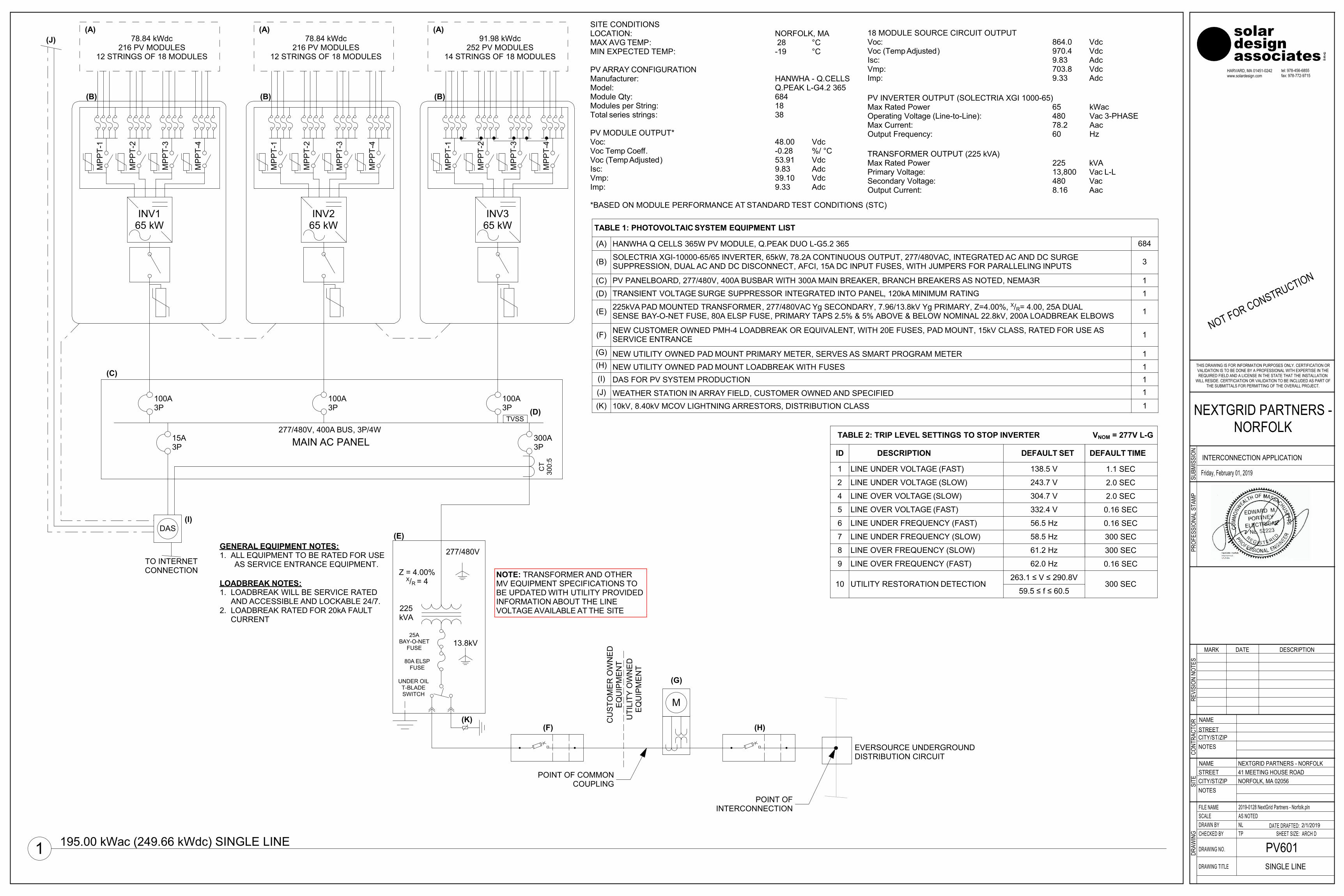
18 MODULE SOURCE CIRCUIT OUTPUT Voc: 864.0 VdcVoc (Temp Adjusted) 970.4 VdcIsc: 9.83 AdcVmp: 703.8 VdcImp: 9.33 Adc
PV INVERTER OUTPUT (SOLECTRIA XGI 1000-65)Max Rated Power 65 kWacOperating Voltage (Line-to-Line): 480 Vac 3-PHASEMax Current: 78.2 AacOutput Frequency: 60 Hz
TRANSFORMER OUTPUT (225 kVA)Max Rated Power 225 kVAPrimary Voltage: 13,800 Vac L-LSecondary Voltage: 480 VacOutput Current: 8.16 Aac
SITE CONDITIONS LOCATION: NORFOLK, MAMAX AVG TEMP: 28 °CMIN EXPECTED TEMP: -19 °C
PV ARRAY CONFIGURATION Manufacturer: HANWHA - Q.CELLSModel: Q.PEAK L-G4.2 365Module Qty: 684Modules per String: 18Total series strings: 38 PV MODULE OUTPUT* Voc: 48.00 VdcVoc Temp Coeff. -0.28 %/ °CVoc (Temp Adjusted) 53.91 VdcIsc: 9.83 AdcVmp: 39.10 VdcImp: 9.33 Adc
*BASED ON MODULE PERFORMANCE AT STANDARD TEST CONDITIONS (STC)M
PP
T-4
(B)M
PP
T-1
78.84 kWdc216 PV MODULES
12 STRINGS OF 18 MODULES
INV165 kW
MP
PT-
2
MP
PT-
3
(A)
MP
PT-
4
(B)
MP
PT-
1
78.84 kWdc216 PV MODULES
12 STRINGS OF 18 MODULES
INV265 kW
MP
PT-
2
MP
PT-
3
(A)
MP
PT-
4
(B)
MP
PT-
1
91.98 kWdc252 PV MODULES
14 STRINGS OF 18 MODULES
INV365 kW
MP
PT-
2
MP
PT-
3
(A)
(D)TVSS
277/480V, 400A BUS, 3P/4W
MAIN AC PANEL
100A3P
300A3P
100A3P
(C)
100A3P
15A3P
(K)
277/480V
Z = 4.00%X/R = 4
80A ELSPFUSE
(E)
13.8kV25A
BAY-O-NETFUSE
225kVA
UNDER OILT-BLADESWITCH
UTI
LITY
OW
NE
DE
QU
IPM
EN
T
CU
STO
ME
R O
WN
ED
EQ
UIP
ME
NT
(F)
NOTE: TRANSFORMER AND OTHERMV EQUIPMENT SPECIFICATIONS TOBE UPDATED WITH UTILITY PROVIDEDINFORMATION ABOUT THE LINEVOLTAGE AVAILABLE AT THE SITE
LOADBREAK NOTES:1. LOADBREAK WILL BE SERVICE RATED
AND ACCESSIBLE AND LOCKABLE 24/7.2. LOADBREAK RATED FOR 20kA FAULT
CURRENT
GENERAL EQUIPMENT NOTES:1. ALL EQUIPMENT TO BE RATED FOR USE
AS SERVICE ENTRANCE EQUIPMENT.
(G)
M
(H)
TO INTERNETCONNECTION
DAS(I)
WEATHER STATION IN ARRAY FIELD, CUSTOMER OWNED AND SPECIFIED 1
(A)
TABLE 1: PHOTOVOLTAIC SYSTEM EQUIPMENT LIST
684
NEW UTILITY OWNED PAD MOUNT LOADBREAK WITH FUSES 1
HANWHA Q CELLS 365W PV MODULE, Q.PEAK DUO L-G5.2 365
3(B)
DAS FOR PV SYSTEM PRODUCTION 1
(F) NEW CUSTOMER OWNED PMH-4 LOADBREAK OR EQUIVALENT, WITH 20E FUSES, PAD MOUNT, 15kV CLASS, RATED FOR USE ASSERVICE ENTRANCE 1
(E) 1225kVA PAD MOUNTED TRANSFORMER, 277/480VAC Yg SECONDARY, 7.96/13.8kV Yg PRIMARY, Z=4.00%, X/R= 4.00, 25A DUALSENSE BAY-O-NET FUSE, 80A ELSP FUSE, PRIMARY TAPS 2.5% & 5% ABOVE & BELOW NOMINAL 22.8kV, 200A LOADBREAK ELBOWS
300 SEC
332.4 V
LINE OVER FREQUENCY (SLOW) 61.2 Hz 300 SEC
2
1
LINE OVER VOLTAGE (FAST)
243.7 V
304.7 V
LINE OVER FREQUENCY (FAST)9 62.0 Hz 0.16 SEC
DEFAULT TIME
5
4
58.5 Hz
56.5 Hz6
2.0 SEC
ID
LINE UNDER FREQUENCY (FAST)
2.0 SEC
LINE UNDER FREQUENCY (SLOW)
0.16 SEC
TABLE 2: TRIP LEVEL SETTINGS TO STOP INVERTER
7
8
DESCRIPTION
LINE UNDER VOLTAGE (SLOW)
LINE OVER VOLTAGE (SLOW)
138.5 V
VNOM = 277V L-G
DEFAULT SET
1.1 SECLINE UNDER VOLTAGE (FAST)
0.16 SEC
59.5 ≤ f ≤ 60.5
263.1 ≤ V ≤ 290.8V300 SECUTILITY RESTORATION DETECTION10
(H)
110kV, 8.40kV MCOV LIGHTNING ARRESTORS, DISTRIBUTION CLASS
(I)
TRANSIENT VOLTAGE SURGE SUPPRESSOR INTEGRATED INTO PANEL, 120kA MINIMUM RATING(D) 1PV PANELBOARD, 277/480V, 400A BUSBAR WITH 300A MAIN BREAKER, BRANCH BREAKERS AS NOTED, NEMA3R(C) 1
(J)
(K)
SOLECTRIA XGI-10000-65/65 INVERTER, 65kW, 78.2A CONTINUOUS OUTPUT, 277/480VAC, INTEGRATED AC AND DC SURGESUPPRESSION, DUAL AC AND DC DISCONNECT, AFCI, 15A DC INPUT FUSES, WITH JUMPERS FOR PARALLELING INPUTS
NEW UTILITY OWNED PAD MOUNT PRIMARY METER, SERVES AS SMART PROGRAM METER 1(G)
CT
300:
5
EVERSOURCE UNDERGROUNDDISTRIBUTION CIRCUIT
(J)
1 195.00 kWac (249.66 kWdc) SINGLE LINE
solardesignassociates in
c
HARVARD, MA 01451-0242 tel: 978-456-6855fax: 978-772-9715www.solardesign.com
NEXTGRID PARTNERS -NORFOLK
REVI
SION
NOT
ES
MARK DATE DESCRIPTION
PROF
ESSI
ONAL
STA
MP
THIS DRAWING IS FOR INFORMATION PURPOSES ONLY. CERTIFICATION ORVALIDATION IS TO BE DONE BY A PROFESSIONAL WITH EXPERTISE IN THEREQUIRED FIELD AND A LICENSE IN THE STATE THAT THE INSTALLATION
WILL RESIDE. CERTFICIATION OR VALIDATION TO BE INCLUDED AS PART OFTHE SUBMITTALS FOR PERMITTING OF THE OVERALL PROJECT.
INTERCONNECTION APPLICATION
Friday, February 01, 2019
CONT
RACT
OR
NAMESTREETCITY/ST/ZIPNOTES
NAMESTREETCITY/ST/ZIPNOTES
SITE
SUBM
ISSI
ON
DATASHEETS
PV603
2019-0128 NextGrid Partners - Norfolk.plnAS NOTEDNLTP SHEET SIZE:
DRAWING NO.
DRAWING TITLE
FILE NAME
CHECKED BYDRAWN BY DATE DRAFTED:
DRAW
ING
SCALE2/1/2019ARCH D
NORFOLK, MA 0205641 MEETING HOUSE ROAD
NOT FOR CONSTRUCTION
NEXTGRID PARTNERS - NORFOLK
Q.PEAK L-G4.2 360-370
1 APT test conditions according to IEC/TS 62804-1:2015, method B (−1500 V, 168 h)2 See data sheet on rear for further
information.
Q.ANTUM SOLAR MODULE
The new solar module Q.PEAK L-G4.2 with power classes up to 370 Wp is the strongest module of its type on the market globally. Powered by 72 Q.ANTUM solar cells Q.PEAK L-G4.2 was specially designed for large solar power plants to reduce BOS costs. Only Q CELLS offers German engineering quality with our unique Q CELLS Yield Security.
THE IDEAL SOLUTION FOR:
Ground-mountedsolar power plants
ANTI PID TECHNOLOGY(APT)
HOT-SPOT PROTECT(HSP)
TRACEABLE QUALITY(TRA.Q™)
YIELD SECURITY
ANTI LID TECHNOLOGY(ALT)
174 modules tested
Best polycrystallinesolar module 2014
Q.PRO-G2 235
MOD:27898 photon.info/laboratory
LOW ELECTRICITY GENERATION COSTS Higher yield per surface area and lower BOS costs thanks to higher power classes and an efficiency rate of up to 18.8 %.
INNOVATIVE ALL-WEATHER TECHNOLOGYOptimal yields, whatever the weather with excellent low-light and temperature behavior.
ENDURING HIGH PERFORMANCELong-term yield security with Anti LID Technology, Anti PIDTechnology1, Hot-Spot Protect and Traceable Quality Tra.Q™.
EXTREME WEATHER RATINGHigh-tech aluminum alloy frame, certified for high snow (5400 Pa) and wind loads (2400 Pa).
A RELIABLE INVESTMENTInclusive 12-year product warranty and 25-year linear performance guarantee2.
MECHANICAL SPECIFICATION
Q CELLS PERFORMANCE WARRANTY PERFORMANCE AT LOW IRRADIANCE
Typical module performance under low irradiance conditions in comparison to STC conditions (25 °C, 1000 W/m2).
IRRADIANCE [W/m²]
RELA
TIVE
EFF
ICIE
NCY
[%
]
200 400 600 800 1000
110
100
90
80
Format 78.5 in × 39.4 in × 1.38 in (including frame)(1994 mm × 1000 mm × 35 mm)
Weight 52.9 lbs (24 kg)
Front Cover 0.13 in (3.2 mm) thermally pre-stressed glass with anti-reflection technology
Back Cover Composite film
Frame Anodized aluminum
Cell 6 × 12 monocrystalline Q.ANTUM solar cells
Junction box 3.35-4.37 in × 2.36-3.15 in × 0.59-0.75 in (85-111 × 60-80 × 15-19 mm), Protection class IP67, with bypass diodes
Cable 4 mm² Solar cable; (+) ≥ 47.24 in (1200 mm), (−) ≥ 47.24 in (1200 mm)
Connector MC4 or MC4-EVO 2, IP 65 and IP68
≥ 1200 mm
1000 mm
1308 mm
1994 mm
35 mm
Anschlussdose
4 × Befestigungspunkte (DETAIL A)8 × Entwässerungslöcher 3 × 6 mm
Anschlusskabel mit Steckverbinder
Rahmen
6 × Erdungsbohrung , Ø 4.5 mm
DETAIL A16 mm
8.5 mm25.5 mm
949 mm
4 × Entwässerungslöcher 11.9 × 11.9 mm
DETAIL B10 mm
7 mm25 mm
4 × Befestigungspunkte Tracker System (DETAIL B)
950 mm
400 mm150 mm 343 mm
CertifiedUL 1703(254141)
PROPERTIES FOR SYSTEM DESIGNMaximum System Voltage VSYS [V] 1500 (IEC) / 1500 (UL) Safety Class II
Maximum Series Fuse Rating [A DC] 20 Fire Rating C (IEC) / TYPE 1 (UL)
Design load, push (UL)2 [lbs/ft2] 75 (3600 Pa) Permitted module temperatureon continuous duty
− 40 °F up to +185 °F(− 40 °C up to +85 °C)
Design load, pull (UL)2 [lbs/ft2] 33 (1600 Pa) 2 see installation manual
QUALIFICATIONS AND CERTIFICATES PACKAGING INFORMATIONNumber of Modules per Pallet 29
Number of Pallets per 40' Container 22
Number of Pallets per 53' Container 26
Pallet Dimensions ( L × W × H ) 81.3 × 45.3 × 46.9 in(2065 × 1150 × 1190 mm)
Pallet Weight 1671 lbs (758 kg)
NOTE: Installation instructions must be followed. See the installation and operating manual or contact our technical service department for further information on approved installation and use of this product.
RELA
TIVE
EFF
ICIE
NCY
COM
PARE
D TO
NOM
INAL
POW
ER [
%] 100
95
90
85
80
75
155 25200 10
YEARS
98Q CELLS
Industry standard for tiered warranties*
Industry standard for linear warranties*
*Standard terms of guarantee for the 10 PV companieswith the highest production capacity in 2014 (as at: September 2014)
ELECTRICAL CHARACTERISTICSPOWER CLASS 360 365 370
MINIMUM PERFORMANCE AT STANDARD TEST CONDITIONS, STC1 (POWER TOLERANCE +5 W / −0 W)
Min
imum
Power at MPP2 PMPP [W] 360 365 370
Short Circuit Current* ISC [A] 9.77 9.83 9.89
Open Circuit Voltage* VOC [V] 47.71 48.00 48.28
Current at MPP* IMPP [A] 9.26 9.33 9.41
Voltage at MPP* VMPP [V] 38.89 39.10 39.32
Efficiency2 η [%] ≥ 18.1 ≥ 18.3 ≥ 18.6
MINIMUM PERFORMANCE AT NORMAL OPERATING CONDITIONS, NOC3
Min
imum
Power at MPP2 PMPP [W] 266.4 270.1 273.8
Short Circuit Current* ISC [A] 7.88 7.93 7.97
Open Circuit Voltage* VOC [V] 44.63 44.90 45.17
Current at MPP* IMPP [A] 7.27 7.34 7.40
Voltage at MPP* VMPP [V] 36.63 36.81 36.9811000 W/m², 25 °C, spectrum AM 1.5 G 2 Measurement tolerances STC ± 3%; NOC ± 5% 3 800 W/m², NOCT, spectrum AM 1.5 G * typical values, actual values may differ
TEMPERATURE COEFFICIENTS
Temperature Coefficient of ISC α [% / K] + 0.04 Temperature Coefficient of VOC β [% / K] − 0.28
Temperature Coefficient of PMPP γ [% / K] − 0.39 Normal Operating Cell Temperature NOCT [°F] 113 ± 5.4 (45 ± 3 °C)
IEC 61215 (Ed. 2); IEC 61730 (Ed. 1), Application class A
This data sheet complies with DIN EN 50380.
Specifications subect to technical changes ©
Han
wha
Q C
ELLS
Q
.P
EA
K L-G
4.2
_3
60
-3
70
_2
01
7-1
0_R
ev0
2_N
A
At least 8 of nominal power during first year. Thereafter ma . 0.6 degra-dation per year.At least 2.6 of nominal power up to 10 years.At least 83.6 of nominal power up to 25 years.
All data within measurement tolerances.Full warranties in accordance with the warranty terms of the Q CELLS sales organization of your respective country.
Hanwha Q CELLS America Inc.300 Spectrum Center Drive, Suite 1250, Irvine, CA 92618, USA | TEL +1 949 748 59 96 | EMAIL [email protected] | WEB www.q-cells.us
With U.S. and Global Components
MADE IN THE USA
FeaturesMade in the USA with global componentsBuy American Act (BAA) compliant50kW, 60kW and 65kWBuilt to lastLowest cost of labor/installationAccess to all inverters on-site via WiFi from one locationLowest cost of O&MRemote diagnosticsRemote software & firmware upgrades5-90° installation angles4 MPPTsAdvanced grid-support functionsIntegrated AFCI
OptionsPlug & play MC4 or H4 connectorsWeb-based monitoringRevenue grade metering
Yaskawa Solectria Solar’s XGI 1000 commercial string inverters are designed for high reliability and built with the highest quality components. Components were selected, tested and proven to last beyond their warranty. The XGI 1000 inverters provide advanced grid-support functionality and meet the latest IEEE 1547 and UL 1741 standards for safety. Offering a wide mounting-angle range (5 – 90° from horizontal), the XGI inverters can be installed to meet NEC array-level rapid shutdown requirements. Designed and engineered in Lawrence, MA, the XGI inverters are assembled and tested at Yaskawa America’s facilities in Buffalo Grove, IL. The all new XGI 1000 inverters are Made in the USA with global components and are compliant with the Buy American Act.
SOLECTRIA XGI 1000Premium 3-Ph Transformerless Commercial String Inverters
SOLECTRIA XGI 1000
Specifications
Yaskawa Solectria Solar 360 Merrimack Street Lawrence, MA 01843 solectria.com
1-978-683-9700 [email protected]
DOCR-070604-H | November 2018 © 2018 Yaskawa Solectria Solar
XGI 1000-50/60 XGI 1000-60/60 XGI 1000-60/65 XGI 1000-65/65
DC Input
Absolute Maximum Input Voltage 1000 VDC 1000 VDC 1000 VDC 1000 VDC
Maximum Power Input Voltage Range (MPPT) 580-850 VDC 580-850 VDC 600-850 VDC 600-850 VDC
Operating Voltage Range (MPPT) 350-950 VDC 350-950 VDC 350-950 VDC 350-950 VDC
Maximum Operating Input Current 88.0 A (22.0 A per zone) 105.6 A (26.4 A per zone) 105.6 A (26.4 A per zone) 110.6 A (27.65 A per zone)
Maximum Operating PV Power (per MPPT) 12.8 kW 15.3 kW 15.3 kW 16.6 kW
Maximum Rated PV Input (per MPPT) 18.75 kW 22.5 kW 22.5 kW 24.4 kW
Number of MPP Trackers 4 / 1 (default) 4 / 1 (default) 4 / 1 (default) 4 / 1 (default)
Number of PV Source Circuits (Fused Inputs) 4 per MPPT; 16 total 4 per MPPT; 16 total 4 per MPPT; 16 total 4 per MPPT; 16 totalMaximum PV Current (Isc x 1.25) per Zone /
Single Zone 50 A / 180 A 50 A / 180 A 50 A / 180 A 50 A / 180 A
Maximum Recommended DC to AC Ratio 1.5 1.5 1.5 1.5
AC Output
Nominal Output Voltage 480 VAC, 3-Ph 480 VAC, 3-Ph 480 VAC, 3-Ph 480 VAC, 3-Ph
AC Voltage Range -12 / +10% -12 / +10% -12 / +10% -12 / +10%
Continuous Real Output Power 50 kW 60 kW 60 kW 65 kW
Continuous Apparent Output Power 60 kVA 60 kVA 65 kVA 65 kVA
Maximum Output Current 72.2 A 72.2 A 78.2 A 78.2 A
Nominal Output Frequency 60 Hz 60 Hz 60 Hz 60 Hz
Power Factor (Unity default) +/- 0.85 Adjustable +/- 0.85 Adjustable +/- 0.85 Adjustable +/- 0.85 AdjustableTotal Harmonic Distortions (THD) @ Rated
Power <3% <3% <3% <3%
Grid Connection Type 3-Ph + N/GND 3-Ph + N/GND 3-Ph + N/GND 3-Ph + N/GND
Fault Current Contribution (1 cycle RMS) 93.9 A 93.9 A 101.7 A 101.7 A
Recommended AC Overcurrent Device Rating 100 A (AC Maximum Output Current x 1.25)
Efficiency
Peak Efficiency 98.2% 98.2% 98.2% 98.2%
CEC Average Efficiency 98.0% 98.0% 98.0% 98.0%
Tare Loss <1 W <1 W <1 W <1 W
Temperature
Ambient Temperature Range -40°F to 140°F (-40°C to 60°C)
De-Rating Temperature 122°F (50°C) 113°F (45°C)
Storage Temperature Range -40°F to 167°F (-40°C to 75°C)
Relative Humidity (non-condensing) 0-95%
Operating Altitude 9,842.5 ft (3,000 m)
Communications
Advanced Graphical User Interface WiFi
Communication Interface RJ-45 Ethernet
Third-Party Monitoring Protocol Sunspec Modbus TCP/IP
Web-Based Monitoring Optional
Revenue Grade Metering Optional
Firmware Updates Remote/Local
Testing & Certifications
Safety Listings & Certifications UL 1741 / IEEE 1547, UL 1699B, UL 1998
Advanced Grid Support Functionality Rule 21, UL 1741SA (pending)
Testing Agency Intertek
FCC Compliance FCC Part 15, Class A
Warranty
Standard Limited Warranty 10 Years
Enclosure
Acoustic Noise Rating 55 dBA @ 3 m
DC Disconnect Integrated, 2 Pole
Mounting Angle 5-90° Measured from horizontal
Dimensions (H x W x D) 45.8 in. x 28.3 in. x 11.6 in. (1163 x 719 x 295 mm)
Weight Inverter: 117 lbs (53.07 kg); Wiring Box: 49 lbs (22.22 kg)
Enclosure Rating and Finish Type 4, Polyester Powder-Coated Aluminum
Specifications subject to change.
General Eaton protects both distribu tion apparatus from damag ing currents and dis tri bution systems from failed apparatus with its Cooper Power series current sensing Bay-O-Net fuse link that is used in Eaton's Cooper Power series Bay-O-Net fuse assemblies (see Catalog CA132015EN Sidewall-Mounted and Cover-Mounted Bay-O-Net Fuse Assembly). They are used on single-phase con ven-tional and self-protected distribution transformers and other apparatus rated through 500 kVA, and on three-phase equip ment through 1500 kVA.
A Bay-O-Net fuse is ideal for use in a two-fuse protection scheme with a current-limiting backup fuse. In this arrangement, secondary faults and overload currents are cleared by the Bay-O-Net fuse, and high level faults are cleared by the current-limiting fuse. The two fuses are connected in series, and are coordinated so that the current-limiting fuse operates only upon internal equipment failure. (See Catalog CA132013EN ELSP Current-Limiting Backup Fuse to order an ELSP current-limiting backup fuse.) If the Bay-O-Net fuse will not be used in series with a current-limiting fuse, an isolation link is required. (See Catalog CA132012EN Isolation Link.)
Bay-O-Net fuses are com pa rable in cost to internal cartridge fuses but have the ad van tages of being field-replaceable. Bay-O-Net fuses can easily be co ordinated with upstream devices.
INSTALLATIONNo special tools are required. A hotstick is used to remove the Bay-O-Net fuse cartridge holder from non-pressurized apparatus. The fuse cartridge is then replaced, and the holder reinserted using a hotstick. Refer to Service Information MN132002EN Bay-O-Net Fuse Re-fusing Installation Instructions for re-fusing instructions.
Current sensing Bay-O-Net fuse link
Fusing EquipmentCatalog Data CA132009EN
Effective February 2015Supersedes 240-45 September 2012
COOPER POWERSERIES
Figure 1. Fuse Link features and dimensional information.
ote:N Dimensions given are for reference only.
SILVER-PLATED BRASS CONTACTSProvide reliable positive current interchange.
0.365" - 0.382" Dia.(9.3 mm - 9.7 mm)
CORROSION-RESISTANT ELEMENT Provides reliable fuse operation.
TEFLON® TUBEProvides track-free bore to with-stand full-rated voltage after fuse operation.
* Add suffix "B" to order individual fuse; add "M" to order bag of 50.
Table 2. Bay-O-Net Fuse LinkContinuousCurrentRating (A)
CatalogNumber*
6 4000353C04
10 4000353C06
15 4000353C08
25 4000353C10
40 4000353C12
65 4000353C14
100 4000353C16
140 4000353C17
3.86" - 3.90 "(98 mm - 99 mm)
Table 1. Electrical Ratings and Characteristics
Voltage(kV) Catalog Number
Maximum Single-Phase Interrupting Rating*
Cover-Mounted Assembly (rms symmetrical)in Mineral Oil
Sidewall-Mounted Assembly(rms symmetrical)in Mineral Oil
Sidewall-Mounted Assembly (rms symmetrical) in Envirotemp™ FR3™ Fluid
8.3
353C04-C08 3500 A 3500 A 3500 A
353C10-C12 3500 A 3500 A 2500 A
353C14-C17 3500 A 3500 A 3500 A
15.5
353C04-C08 2500 A 2500 A 2500 A
353C10-C12 2500 A 2500 A 1500 A
353C14-C17 2500 A 2500 A 2500 A
23.0 353C04-C17 1000 A 1000 A 1000 A* In Eaton's Cooper Power series Bay-O-Net assemblies only. Where available fault current exceeds rated value, coordinated current-limiting fusing such as an ELSP (Catalog CA132013EN) or approved
equivalent must be provided.
Ordering informationTo order a current sensing Bay-O-Net fuse link, determine the requirements of the application from Tables 3 and 4 and specify the fuse required from Table 2.
2
Catalog Data CA132009ENEffective February 2015
Current sensing Bay-O-Net fuse link
www.cooperpower.com
GeneralEaton offers its Cooper Power™ series ELSP current-limiting backup fuse that is used in series with low current primary protection devices such as a Bay-O-Net fuse or its Cooper Power series MagneX™ interrupter.
The ELSP fuse is designed for use in transformer oil, Envirotemp™ FR3™ fluid, or an approved equivalent.
The fuse’s highly efficient current-limiting section minimizes the effects of high fault current stresses on equipment and the distribution system. Its minimum interrupting rating is coordinated with that of a low current interrupter to avoid undesirable low current operation; yet its maximum interrupting rating will clear the highest fault currents likely to occur. Higher continuous current ratings can be achieved by connecting two fuses in parallel.
ApplicationThe ELSP fuse is used in transformers to protect and isolate faulted equipment. When connected in series with a low current primary protection device, the fuse becomes an element of a two-part protection system that gives a full range of fault protection.
This two-part system provides low current protection with the replaceable expulsion fuse or resettable MagneX interrupter, and it adds the energy-limiting protection of a current-limiting fuse. Together, they coordinate easily with upstream and downstream devices.
ELSP current-limiting backup fuse
Catalog Data CA132013EN
Effective March 2015 Supersedes TD132002EN October 2014
COOPER POWERSERIES
Table 3. Dimensional Information
Voltage (kV)Current Rating (A) ELSP Part Numbers
Dimension A (See Figure 1)Inches (mm)
Diameter Tube
Description
Dimension B(See Figures1,2)Inches (mm)
Dimension CSee Figures 1,2)Inches (mm)
8.3
30 CBUC08030C100 7.2 (183) 6.0 (152) 2.1 (53) 8.3 kV 30 A40 CBUC08040C100 7.2 (183) 6.0 (152) 2.1 (53) 8.3 kV 40 A50 CBUC08050C100 7.2 (183) 6.0 (152) 2.1 (53) 8.3 kV 50 A65 CBUC08065C100 7.2 (183) 6.0 (152) 2.1 (53) 8.3 kV 65 A80 CBUC08080C100 9.6 (244) 8.4 (214) 2.1 (53) 8.3/9.9 kV 80 A100 CBUC08100C100 9.6 (244) 8.4 (214) 2.1 (53) 8.3/9.9 kV 100 A125 CBUC08125C100 9.6 (244) 8.4 (214) 2.1 (53) 8.3 kV 125 A150 CBUC08150D100 – 11.4 (289) 3.0 (76) 8.3 kV 150 A165 CBUC08165D100 – 11.4 (289) 3.0 (76) 8.3 kV 165 A180 CBUC08180D100 – 11.4 (289) 3.0 (76) 8.3 kV 180 A250 CBUC08250D100 – 11.4 (289) 3.0 (76) 8.3 kV 250 A
9.9
30 CBUC09030C100 9.6 (244) 8.4 (214) 2.1 (53) 9.9 kV 30 A40 CBUC09040C100 9.6 (244) 8.4 (214) 2.1 (53) 9.9 kV 40 A50 CBUC09050C100 9.6 (244) 8.4 (214) 2.1 (53) 9.9 kV 50 A65 CBUC09065C100 9.6 (244) 8.4 (214) 2.1 (53) 9.9 kV 65 A
15.5
30 CBUC15030C100 9.7 (247) 8.5 (216) 2.1 (53) 15.5 kV 30 A40 CBUC15040C100 9.7 (247) 8.5 (216) 2.1 (53) 15.5 kV 40 A50 CBUC15050C100 9.7 (247) 8.5 (216) 2.1 (53) 15.5 kV 50 A65 CBUC15065C100 9.7 (247) 8.5 (216) 2.1 (53) 15.5 kV 65 A80 CBUC15080C100 14.0 (356) 12.8 (325) 2.1 (53) 15.5/17.2 kV 80 A100 CBUC15100C100 14.0 (356) 12.8 (325) 2.1 (53) 15.5/17.2 kV 100 A125 CBUC15125C100 16.9 (429) 15.6 (396) 2.1 (53) 15.5/17.2 kV 125 A150 CBUC15150D100 – 15.95 (405) 3.0 (76) 15.5 kV 150 A165 CBUC15165D100 – 15.95 (405) 3.0 (76) 15.5 kV 165 A180 CBUC15180D100 – 15.95 (405) 3.0 (76) 15.5 kV 180 A
17.2
30 CBUC17030C100 14.0 (356) 12.8 (325) 2.1 (53) 17.2 kV 30 A40 CBUC17040C100 14.0 (356) 12.8 (325) 2.1 (53) 17.2 kV 40 A50 CBUC17050C100 14.0 (356) 12.8 (325) 2.1 (53) 17.2 kV 50 A65 CBUC17065C100 14.0 (356) 12.8 (325) 2.1 (53) 17.2 kV 65 A
23
30 CBUC23030C100 12.7 (323) 11.5 (292) 2.1 (53) 23 kV 30 A40 CBUC23040C100 12.7 (323) 11.5 (292) 2.1 (53) 23 kV 40 A50 CBUC23050C100 12.7 (323) 11.5 (292) 2.1 (53) 23 kV 50 A65 CBUC23065C100 12.7 (323) 11.5 (292) 2.1 (53) 23 kV 65 A80 CBUC23080C100 16.9 (429) 15.6 (396) 2.1 (53) 23 kV 80 A100 CBUC23100C100 16.9 (429) 15.6 (396) 2.1 (53) 23 kV 100 A125 CBUC23125D100 – 18.9 (480) 3.0 (76) 23 kV 125 A150 CBUC23150D100 – 18.9 (480) 3.0 (76) 23 kV 150 A165 CBUC23165D100 – 18.9 (480) 3.0 (76) 23 kV 165 A
38
50 CBUC38050D100 – 15.95 (405) 3.0 (76) 38 kV 50 A65 CBUC38065D100 – 15.95 (405) 3.0 (76) 38 kV 65 A80 CBUC38080D100 – 19.2 (487) 3.0 (76) 38 kV 80 A100 CBUC38100D100 – 19.2 (487) 3.0 (76) 38 kV 100 A120 CBUC38120D100 – 21.9 (556) 3.0 (76) 38 kV 120 A140 CBUC38140D100 – 24.7 (627) 3.0 (76) 38 kV 140 A
Ordering informationTo order an ELSP current-limiting fuse, de ter mine the am per age and voltage ratings of the ap pli ca tion and specify the fuse required from Table 3. For parallel fusing, order two fuses.
New part numbering guide:
C Cooper
B Backup
U Under-oil
C Clamp-Mounted
XX Voltage Rating
XXX Current Rating
CD
2 inch3 inch
1 Single Barrel Design
00 Revision Code
M Metric End Connection
4
Catalog Data CA132013ENEffective March 2015
ELSP current-limiting backup fuse
www.cooperpower.com