
Effect of Applied Voltage on Electroreduction with Controlled ...
10
© 2015 ISIJ 1 * Corresponding author: E-mail: [email protected] DOI: http://dx.doi.org/10.2355/isijinternational.ISIJINT-2014-826 1. Introduction The iron and steel metallurgy industry is one of the key emission sources of greenhouse gas. 1,2) Production of metallic iron through the molten oxide electrolysis (MOE) process using inert electrode is an alternative route of iron- making to eliminate CO 2 emissions. 3–7) However, it causes such problems as low efficiency of electrolysis (to 30%), 5) difficulty in the selection of candidate anode materials 6) and controlling side reaction and so on. In order to overcome these disadvantages of the electrolysis, a zirconia based solid electrolyte with strong selective permeability for oxy- gen ions can be employed to constitute the electrolytic cell and isolate the cathode and the anode during electrolysis. In the electrolytic cell the zirconia membrane is used as a medium guiding a directional oxygen flow, the oxygen ions from molten oxide are transferred through the membrane by applying an external voltage between the electrodes, and then an electrolytic method with controlled oxygen flow (COF) is built up. 8) Pal and his co-workers have described this new metallurgical method as the solid-oxide oxygen- ion-conducting membrane (SOM) process. 9–14) With this Effect of Applied Voltage on Electroreduction with Controlled Oxygen Flow of Molten Slag Containing FeO at 1 723 K Yunming GAO, 1,2) * Chao DUAN, 2) Yingbin YANG, 2) Dong RUAN, 2) Chuanghuang YANG 2) and Chuan HONG 2) 1) The State Key Laboratory of Refractories and Metallurgy, Wuhan University of Science and Technology, P.O. 122 box, 947 Heping Road, Wuhan, 430081 China. 2) Key Laboratory for Ferrous Metallurgy and Resources Utilization of Ministry of Education, Wuhan University of Science and Technology, P.O. 122 box, 947 Heping Road, Wuhan, 430081 China. (Received on December 21, 2014; accepted on July 14, 2015; J-Stage Advance published date: September 15, 2015) This paper reports on electroreduction with controlled oxygen flow (COF) for extraction of iron along with oxygen by-product from molten slag containing FeO at 1 723 K. An electrolytic cell with COF was constructed by a cathode and a porous platinum anode sintered on a one-end-closed magnesia partially stabilized zirconia based solid electrolyte tube. The process for electroreduction with COF was analyzed. Effect of applied voltage on electroreduction behavior of FeO in SiO 2 –CaO–Al 2 O 3 –MgO molten slag with iron rod serving as cathode was investigated by means of the linear sweep and the potentiostatic elec- trolysis. The possibility of zirconia membrane as conductive noncorrosive anode material was also dis- cussed. The results show that decreased oxygen partial pressure in anode atmosphere can contribute to lower decomposition voltage of FeO in molten slag. Higher applied voltage results in better effect of FeO electroreduction. Electrolytic product can be pure iron with dendrite or ferrosilicon alloy based on applied voltage. Besides, the phase transformation of zirconia grain and the slag penetration can lead to an increase of electronic conductivity of the zirconia membrane. The corrosion of the molten slag to the zir- conia membrane during electrolysis is evidently aggravated by large the applied voltage. In order to obtain pure iron and minimize the corrosion of the molten slag to the zirconia membrane under this condition of experimentation, the applied voltage of 1.5 V is preferred. KEY WORDS: electroreduction; controlled oxygen flow; molten slag containing FeO; zirconia based solid electrolyte; decomposition voltage. principle and method, they have extracted the desired metals such as Mg, Ti, Ta and so on from their respective oxide containing molten salt systems at a temperature not more than 1 473 K, the production of some metals has proven to be promising in the laboratory or even at a pilot scale. Gao has also obtained Fe from iron oxide containing molten slag systems at higher temperatures. 15,16) As a new emerging green metallurgical technique, the electrolysis with COF has many advantages such as high efficiency of electrolysis (near 100%), 11) less interference, compact route with emis- sion of oxygen by-product. Galvanic cells containing zirconia based solid electro- lyte are used for a number of scientific and technological applications at high temperatures and these applications can be classified according to the mode of operation of the electrochemical cells. 17) It is well known the oxygen sen- sors containing zirconia based solid electrolyte are utilized extensively throughout the steelmaking process 18–22) and several investigators have also explored the use of zirco- nia probes to measure the activity of FeO x within the slag phase. 23–28) In these applications, the cells are operated in an equilibrium mode and the open circuit voltage (OCV) is measured. In other applications, a dynamic mode of opera- tion is employed and the close circuit current or voltage is measured as a function of time. Cells operating in this ISIJ International, Advance Publication by J-STAGE, DOI: 10.2355/isijinternational.ISIJINT-2014-826
-
Upload
khangminh22 -
Category
Documents
-
view
0 -
download
0
Transcript of Effect of Applied Voltage on Electroreduction with Controlled ...

ISIJ International, Vol. 55 (2015), No. 10
© 2015 ISIJ1
ISIJ International, Vol. 55 (2015), No. 10, pp. 1–10
* Corresponding author: E-mail: [email protected]: http://dx.doi.org/10.2355/isijinternational.ISIJINT-2014-826
1. Introduction
The iron and steel metallurgy industry is one of the key emission sources of greenhouse gas.1,2) Production of metallic iron through the molten oxide electrolysis (MOE) process using inert electrode is an alternative route of iron-making to eliminate CO2 emissions.3–7) However, it causes such problems as low efficiency of electrolysis (to 30%),5) difficulty in the selection of candidate anode materials6) and controlling side reaction and so on. In order to overcome these disadvantages of the electrolysis, a zirconia based solid electrolyte with strong selective permeability for oxy-gen ions can be employed to constitute the electrolytic cell and isolate the cathode and the anode during electrolysis. In the electrolytic cell the zirconia membrane is used as a medium guiding a directional oxygen flow, the oxygen ions from molten oxide are transferred through the membrane by applying an external voltage between the electrodes, and then an electrolytic method with controlled oxygen flow (COF) is built up.8) Pal and his co-workers have described this new metallurgical method as the solid-oxide oxygen-ion-conducting membrane (SOM) process.9–14) With this
Effect of Applied Voltage on Electroreduction with Controlled Oxygen Flow of Molten Slag Containing FeO at 1 723 K
Yunming GAO,1,2)* Chao DUAN,2) Yingbin YANG,2) Dong RUAN,2) Chuanghuang YANG2) and Chuan HONG2)
1) The State Key Laboratory of Refractories and Metallurgy, Wuhan University of Science and Technology, P.O. 122 box, 947 Heping Road, Wuhan, 430081 China. 2) Key Laboratory for Ferrous Metallurgy and Resources Utilization of Ministry of Education, Wuhan University of Science and Technology, P.O. 122 box, 947 Heping Road, Wuhan, 430081 China.
(Received on December 21, 2014; accepted on July 14, 2015; J-Stage Advance published date: September 15, 2015)
This paper reports on electroreduction with controlled oxygen flow (COF) for extraction of iron along with oxygen by-product from molten slag containing FeO at 1 723 K. An electrolytic cell with COF was constructed by a cathode and a porous platinum anode sintered on a one-end-closed magnesia partially stabilized zirconia based solid electrolyte tube. The process for electroreduction with COF was analyzed. Effect of applied voltage on electroreduction behavior of FeO in SiO2–CaO–Al2O3–MgO molten slag with iron rod serving as cathode was investigated by means of the linear sweep and the potentiostatic elec-trolysis. The possibility of zirconia membrane as conductive noncorrosive anode material was also dis-cussed. The results show that decreased oxygen partial pressure in anode atmosphere can contribute to lower decomposition voltage of FeO in molten slag. Higher applied voltage results in better effect of FeO electroreduction. Electrolytic product can be pure iron with dendrite or ferrosilicon alloy based on applied voltage. Besides, the phase transformation of zirconia grain and the slag penetration can lead to an increase of electronic conductivity of the zirconia membrane. The corrosion of the molten slag to the zir-conia membrane during electrolysis is evidently aggravated by large the applied voltage. In order to obtain pure iron and minimize the corrosion of the molten slag to the zirconia membrane under this condition of experimentation, the applied voltage of 1.5 V is preferred.
KEY WORDS: electroreduction; controlled oxygen flow; molten slag containing FeO; zirconia based solid electrolyte; decomposition voltage.
principle and method, they have extracted the desired metals such as Mg, Ti, Ta and so on from their respective oxide containing molten salt systems at a temperature not more than 1 473 K, the production of some metals has proven to be promising in the laboratory or even at a pilot scale. Gao has also obtained Fe from iron oxide containing molten slag systems at higher temperatures.15,16) As a new emerging green metallurgical technique, the electrolysis with COF has many advantages such as high efficiency of electrolysis (near 100%),11) less interference, compact route with emis-sion of oxygen by-product.
Galvanic cells containing zirconia based solid electro-lyte are used for a number of scientific and technological applications at high temperatures and these applications can be classified according to the mode of operation of the electrochemical cells.17) It is well known the oxygen sen-sors containing zirconia based solid electrolyte are utilized extensively throughout the steelmaking process18–22) and several investigators have also explored the use of zirco-nia probes to measure the activity of FeOx within the slag phase.23–28) In these applications, the cells are operated in an equilibrium mode and the open circuit voltage (OCV) is measured. In other applications, a dynamic mode of opera-tion is employed and the close circuit current or voltage is measured as a function of time. Cells operating in this
ISIJ International, Advance Publication by J-StageISIJ International, Advance Publication by J-STAGEISIJ International, Advance Publication by J-StageISIJ International, J-Stage Advanced Publication, DOI: http://dx.doi.org/10.2355/isijinternational.ISIJINT-2015-@@@
ISIJ International, Advance Publication by J-STAGE, DOI: 10.2355/isijinternational.ISIJINT-2014-826

ISIJ International, Vol. 55 (2015), No. 10
© 2015 ISIJ 2
manner have been used in such applications as diffusion coefficient measurements29–33) and electrolysis with COF which includes electrolytic refining of molten metal34–43) and the above mentioned extraction of metal from molten salt systems.9–14,44,45) However, little work has been done on extraction of metal from high-temperature molten oxide systems. One of the reasons may be attributed to the experi-mental difficulties associated with the operation of high-temperature electrochemical cells, which undergo problems with chemical stability of zirconia based solid electrolyte, electrodes and cell container.
The use of zirconia based solid electrolyte membrane is important in electrolysis process with COF, which not only guides a directional oxygen flow, but also provides a pos-sible way to obtain conductive noncorrosive anode material. Recent studies suggest that SiO2–CaO–MgO–Al2O3 slag system is hopefully used as potential medium for extrac-tion of electrolytic iron.3,4,16) In this work, an electrolytic cell with COF was constructed by a cathode and a porous platinum anode sintered on a one-end-closed magnesia par-tially stabilized zirconia based solid electrolyte (MSZ) tube. Effect of applied voltage on electroreduction behavior of SiO2–CaO–MgO–Al2O3–FeO molten slag contained in MSZ tube was investigated with the electrolytic cell by means of the linear sweep and the potentiostatic electrolysis at 1 723 K, and the corrosion of the molten slag to the zirconia membrane was also examined during electrolysis. This work will act as a foundation for investigations of electroreduc-tion with COF for extraction of metal along with oxygen by-product from molten slag at high temperatures.
2. Experimental
2.1. Preparation of SlagsMother slags for the experiment were prepared from the
analytical reagents (ARs) such as CaCO3, SiO2, Al2O3 and MgO calcined at 1 223 K for 6 h in a muffle furnace. FeO was directly added into the mother slags in the form of fer-rous oxalate (AR) powder.46) Chemical composition of the slag was 25.2% CaO-42.3% SiO2-8.1% Al2O3-14.4% MgO-10% FeO (in mass) with basicity B = CaO %/SiO2 % = 0.6 and low melting point of about 1 573 K (estimated by the thermodynamic software FactSage47)). The above mixed powders were melted in an alumina crucible with high purity at 1 673 K for 1 h under purified Ar gas, and then quenched in water. The pre-melted slag was collected and placed in silica gel contained desiccator for ready use.
2.2. Construction of Electrolytic CellThe electrolytic cell consists of a one-end-closed MSZ
tube and two electrodes, the schematic structure of electro-lytic cell is shown in Fig. 1. The MSZ tube also functions as oxygen ionic membrane between cathode and anode. The MSZ tube has 11.5 mm inner diameter, 14.0 mm outer diameter and 58.0 mm in length, and contained 2.18 mass% MgO. The outer surface of the MSZ tube in the closed end was uniformly coated platinum paste (supplied by Sino-Platinum Metals Co., Ltd, China) with self-made feather brush. After airing of the coating, the MSZ tube was placed in the muffle furnace with open door to sinter for 30 min at 1 173 K. A porous platinum anode (5.28 cm2 in area)
with good conductivity (the resistance value was less than 0.2 ohms between any two points on the anode), uniform covering and strong adhesion on the outer surface of the tube was obtained. A Pt wire (0.5 mm in diameter, 750 mm in length) was connected to the porous platinum anode and served as the current lead. Approximately 3.7 g pre-melted slag was loaded inside the MSZ tube for each time. An iron rod (about 2.5 mm in diameter, 800 mm in length, purity not less than 99.99 mass%) served as the cathode. It was prepared from iron rod with original diameter of 4 mm by grinding wheel and fine grade of sandpapers. The cell with COF constructed was expressed as follows:
Fe rod FeO) MSZ air Ptslag(
2.3. Experimental MethodsFor the convenience of operation, the MSZ tube was
extended with a long alumina tube (15 mm inner diameter, 80 mm in length) by high-temperature cement, and the electrolytic cell unit was vertically placed to the constant temperature area in the vertical tube furnace heated by MoSi2 elements. The purified dry argon was introduced into the chamber of the furnace and the MSZ tube at a flow rate of 400 mL/min and 40 mL/min respectively. The furnace was programmed to heat at the rate of 5 K/min to 1 723 K. At the same time of holding temperature, a CHI1140A type electrochemical workstation (produced by Shanghai CH Instruments Co., Ltd, China) was connected to the electrode leads. While the iron rod tip electrode lowered, the exact contact point of electrode and the slag surface was determined by observing sudden change of OCV vs time recorded in real-time. Then the iron rod tip electrode was slowly inserted in the slag to a depth of 7–8 mm (exercise extra care not to contact the inner wall of the MSZ tube). After the OCV was stabilized, a linear sweep voltammetry (LSV) was performed. The potential was swept with rate of 0.01 V/s in the cathodic direction from the measured OCV to 3.0 V. Subsequently, the argon in the chamber of the furnace was switched to the air with the flow rate still at 400 mL/min, and it was visible that the OCV changed with time during gas switching. The same OCV and LSV were respectively performed again under the condition of the air as the anode atmosphere. Lastly, the potentiostatic electrolysis was conducted while the applied voltage was based on the linear sweep curve.
The experiment ceased in the case of a sudden drop or long-time minor variation in the external current during potentiostatic electrolysis. The sudden drop in the current
Fig. 1. Schematic of the electrolytic cell.
ISIJ International, Advance Publication by J-StageISIJ International, Advance Publication by J-STAGE

ISIJ International, Vol. 55 (2015), No. 10
© 2015 ISIJ3
indicated the electrode might be damaged, while long-time minor variation indicated the reduction reaction of the FeO in the molten slag was basically completed. The furnace was cooled down to room temperature. The cells were cut open, and photos of all samples were taken directly with digital camera. The residues were examined by scanning electron microscope (SEM) (Nova 400 Nano) and the energy dis-persive X-ray spectrometer (EDS) (INCAIE 350 Penta FET X-3). It was not convenient to make further detection on the electroreduction effect of the FeO with any other technique due to small slag amount used in this work.
3. Theoretical Analysis of Electrolysis Process
The molten slag (supporting electrolyte) can be consid-ered mainly as an ionic melt conductive via such positive ions as Ca2+ , Mg2+ and so on,48) thus the transference num-ber of O2− is small in the molten slag and the O2− transfers mainly through diffusion. In the MSZ solid electrolyte membrane, however, the O2− transference number is close to 1 when the membrane is exposed in the air, and the O2− transfers mainly through electromigration.
Assumed that the FeO is the only electroactive species in the molten slag under the condition of the experiment described herein. Based on the principle of electroreduction with COF,8) in case of electrolysis with applied voltage, the Fe2+ in the molten slag diffuses toward the cathode, and the Fe2+ is reduced at the cathode. The cathodic reaction is given by Eq. (1).
Fe e Fe2 2+ + = .............................. (1)
At the same time, the O2− in the molten slag diffuses toward the interface of slag/MSZ tube, crosses the slag/MSZ inter-face into the MSZ membrane, and passes through the MSZ membrane before reaching the Pt anode, where the O2− is oxidized to O2 and O2 escapes into the gas. The anodic reac-tion is given by Eq. (2).
O O e221 2 2− = +/ ........................... (2)
The overall transformation during applied voltage can be described by Eq. (3).
Fe O Fe O2 221 2+ −+ = + / .................... (3)
or
( ) /FeO Fe O= +1 2 2 ......................... (3′)
Therefore, oxygen gas is evolved at the anode and iron is obtained at the cathode. The Gibbs free-energy change for Eq. (3′) is given by Eq. (4). The symbols used in this paper are defined in the Appendix.
∆ ∆G G RTa p
a= +0 ln
Fe O (anode)1/2
FeO
2 ................. (4)
The value of aFe is 1 when pure iron rod is used as the cathode. At a given FeO content in molten slag, the value of aFeO can be obtained through theoretical calculation by thermodynamics software FactSage.47) Under the condition of the air as the anode atmosphere, pO anode2 ( ) equals 0.21.
For the limiting case when the applied current approaches zero, Eq. (5) becomes valid.
∆G nFE= − n ............................... (5)
For the general case when the applied current is not equal to zero, under the condition that the slag remains electrically neutral and that no accumulation of oxygen occurs in the cell, the individual flux can be expressed by Eqs. (6) and (7).
J A J AI
FFe cathode O slag/ZrOO
2 2 2
2
+ −
−
× = × =2
............ (6)
and
J DC Cb i
i ii i
i
=−δ
............................. (7)
For convenience, the conduction mechanism in the cell can be explained using an equivalent circuit model under the condition of applied DC voltage.10,12,14,16) It is considered that the effect of capacitance might exist more or less in the actual process. However, as the preliminary study for the electroreduction of molten slag, the terms of capacitors are neglected in the equivalent circuit. In general, the overvolt-age, associated with the reaction step of mass transfer or charge transfer, is represented by a resistance, and the MSZ membrane and the molten slag are treated as mixed con-ductor conductive via ions and electrons. Considering the slag in series with the MSZ membrane, the cell equivalent circuit representing all the voltages and the resistance ele-ments is shown in Fig. 2. The relation between the current in all parts of the circuit and the resistance and the voltage can be derived as shown in Eqs. (8) to (11) according to Kirchhoff’s Law on Current and Voltage in electrotechnics.
I I Iex O e2= +− ............................... (8)
IR R
ER R
E
R R R
Oex
apex
n
ex
2
1 1 1 1
1 1 11 2
1 2
− =− +
+ +............. (9)
IR R
ERE
R R R
eex
ap n
ex
=+
+ +
1 1 1
1 1 12 1
1 2
................... (10)
IR R R
ERE
R R R
exex 1
ap n
ex
=+
−
+ +
1 1 1 1
1 1 12 1
1 2
............ (11)
Fig. 2. Equivalent circuit of the electrolytic cell with controlled oxygen flow.
ISIJ International, Advance Publication by J-StageISIJ International, Advance Publication by J-STAGE

ISIJ International, Vol. 55 (2015), No. 10
© 2015 ISIJ 4
where R1 and R2 are defined in Eqs. (12) and (13), respec-tively.
R R R R R1 = + + +ct mt ZrOi
slagi
2 ................. (12)
R R R2 = +ZrOe
slage
2 .......................... (13)
The electroreduction rate of the FeO in the slag has a close relationship with the oxygen ionic current flowing through the MSZ membrane. The larger the oxygen ionic current, the faster the FeO reduces. It is necessary for elec-troreduction of the FeO in the slag that the oxygen ionic current should be more than zero. Hence, the minimum applied voltage can be determined as shown in Eq. (14) based on Eq. (9).
ER
REap
exn≥ +
1
2
......................... (14)
The presence of an electronic current acts as an internal short in the electrolysis process. It is obvious that internal electronic current (Ie) can decrease process efficiency. The MSZ membrane is a known oxygen ionic electrolyte under the air, so it blocks electronic current, and it has a very high electronic resistance (RZrO
e2). Consequently, Eq. (9) can be
simplified as Eq. (15) for the ideal case where the MSZ membrane exhibits pure ionic conduction.
IE E
R R R R R
E E
R R
E E
R
Oap n
ct mt ZrOi
slagi
ex
ap n
1 ex
ap n
c
2
2
− =−
+ + + +
=−+
=−
tt mt ohmic+ +R R
........... (15)
where Rohmic is defined in Eq. (16).
R R R Rohmic ZrOi
slagi
ex2
= + + ................... (16)
The charge transfer resistance may be assumed to be negligibly small at high temperatures. Since RZrO
e2 is very
large, there is no internal electronic current (Ie) flowing through the MSZ membrane. In this case, the oxygen ionic current (IO2−) is approximately equal to the external current (Iex). The applied voltage overcomes the Nernst voltage to decompose the FeO in the slag and transport the oxygen ions, and results in oxygen ionic current depending on the total ohmic resistance (Rohmic) and impedances associated with overvoltage in the cell.
The above equations and the cell equivalent circuit give the complex relations of the oxygen ionic current ( IO2−) and some factors such as Eap, En( pO anode2 ( ), aFe, aFeO, T), DFe2+, DO2−, A, Rohmic, Rmt and so on. It provides a theory founda-tion on the electroreduction with COF. In order to increase the oxygen ionic current and accelerate the electroreduc-tion rate, some measures can be taken based on the above relations. For examples, the oxygen ionic current flowing through the cell will increase with the increase of Eap and the decreases of En or Rohmic. These observations can be noticed during the electrolysis experiments. It is likely to develop further the overall kinetics model of the reaction to describe the process of electroreduction.49) However, due to the lack of relevant data and some accurate parameters such as Acathode, Rmt, Rohmic, R2 and so on variation with the proceeding of electrolysis, it is still difficult to give an exact quantitative description of electroreduction process in this
work.In the next section, a practical example for extracting
metallic iron with COF from the slag by using iron rod as the cathode will be given to depict qualitatively simple application of these relations. In order to minimize the potential corrosion of the molten slag to the MSZ tube, the slags with low basicity were investigated, the operation temperature was set to be 1 723 K and solid iron could be obtained at the cathode.
4. Results and Discussion
4.1. Linear Sweep CurveIt is well known En for galvanic cell containing zirconia
based solid electrolyte depends on the oxygen chemical potential between the electrodes. When the oxygen ionic transference number in the MSZ membrane equals 1 in an ideal case, the decomposition voltage of FeO contained in the slag, namely, the minimum applied voltage, equals En based on the thermodynamic view point. Therefore, the decomposition voltage of FeO can be determined by extrapolation of the ionic current of straight line part of the current-voltage response curve to zero.
Figure 3 is linear sweep curve for the molten slag under the conditions of different anode atmospheres. It’s found from the value of voltage corresponding to zero value of the curve current on the horizontal axis that, the decomposition voltage of FeO under the condition of the argon anode atmo-sphere is less than that under the condition of the air anode atmosphere. The voltages at the first cross-point of straight line and the horizontal axis at the starting end of sweep curve under the condition of the argon and the air anode atmospheres are 0.76 V and 0.85 V respectively, which, after correction of Fe(+ )-Pt(− ) electrode lead material with thermo-electromotive force (0.023 V) at 1 723 K,50) derived decomposition voltages of the most reducible FeO under the condition of the argon and the air anode atmospheres are 0.78 V and 0.87 V respectively, the latter is consistent with the result of 0.88 V through theoretical calculation by thermodynamics software FactSage.47) This seems to indi-cate that the O2− transference number of the MSZ tube is close to 1 in the initial stage of experiment. The voltages at
Fig. 3. Linear sweep curves of the slag under different anode atmo-spheres (sweep rate: 0.01 V/s). (Online version in color.)
ISIJ International, Advance Publication by J-StageISIJ International, Advance Publication by J-STAGE
ISIJ International, Vol. 55 (2015), No. 10
© 2015 ISIJ5
the cross-point of the second straight line and the horizontal axis of sweep curve under the condition of the argon and the air anode atmospheres are 1.18 V and 1.52 V respectively, which, after correction of with thermo-electromotive force, derived the decomposition voltages of SiO2 under the condi-tion of the argon and the air anode atmospheres are about 1.20 V and 1.54 V respectively. Due to alloy formed by silicon-iron reaction,51) the value of the decomposition volt-age of SiO2 under the condition of the air anode atmosphere is less than 1.58 V from calculation with thermodynamics software FactSage47) when the activity of silicon is 1.
Generally, with higher oxygen partial pressure in the anode atmosphere, the decomposition voltage of FeO increases, this is adverse to electrolysis.
4.2. Electrolysis Current-time CurveUnder the condition of the air as the anode atmosphere,
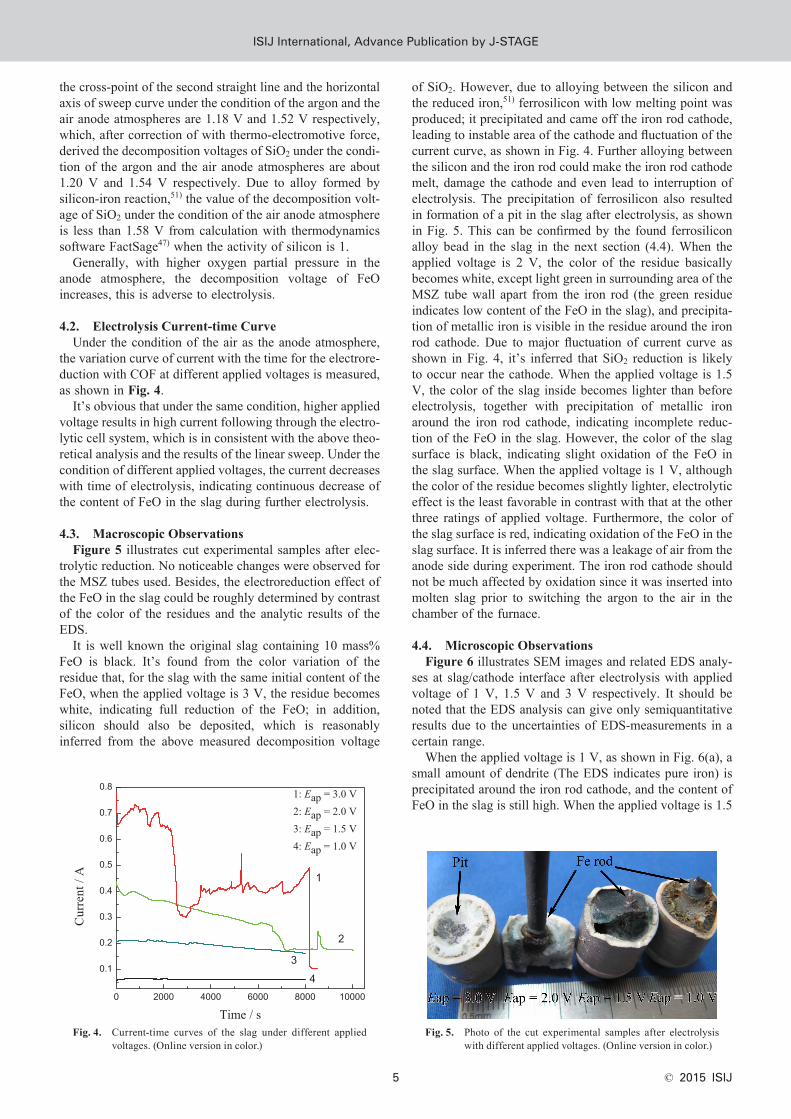
the variation curve of current with the time for the electrore-duction with COF at different applied voltages is measured, as shown in Fig. 4.
It’s obvious that under the same condition, higher applied voltage results in high current following through the electro-lytic cell system, which is in consistent with the above theo-retical analysis and the results of the linear sweep. Under the condition of different applied voltages, the current decreases with time of electrolysis, indicating continuous decrease of the content of FeO in the slag during further electrolysis.
4.3. Macroscopic ObservationsFigure 5 illustrates cut experimental samples after elec-
trolytic reduction. No noticeable changes were observed for the MSZ tubes used. Besides, the electroreduction effect of the FeO in the slag could be roughly determined by contrast of the color of the residues and the analytic results of the EDS.
It is well known the original slag containing 10 mass% FeO is black. It’s found from the color variation of the residue that, for the slag with the same initial content of the FeO, when the applied voltage is 3 V, the residue becomes white, indicating full reduction of the FeO; in addition, silicon should also be deposited, which is reasonably inferred from the above measured decomposition voltage
of SiO2. However, due to alloying between the silicon and the reduced iron,51) ferrosilicon with low melting point was produced; it precipitated and came off the iron rod cathode, leading to instable area of the cathode and fluctuation of the current curve, as shown in Fig. 4. Further alloying between the silicon and the iron rod could make the iron rod cathode melt, damage the cathode and even lead to interruption of electrolysis. The precipitation of ferrosilicon also resulted in formation of a pit in the slag after electrolysis, as shown in Fig. 5. This can be confirmed by the found ferrosilicon alloy bead in the slag in the next section (4.4). When the applied voltage is 2 V, the color of the residue basically becomes white, except light green in surrounding area of the MSZ tube wall apart from the iron rod (the green residue indicates low content of the FeO in the slag), and precipita-tion of metallic iron is visible in the residue around the iron rod cathode. Due to major fluctuation of current curve as shown in Fig. 4, it’s inferred that SiO2 reduction is likely to occur near the cathode. When the applied voltage is 1.5 V, the color of the slag inside becomes lighter than before electrolysis, together with precipitation of metallic iron around the iron rod cathode, indicating incomplete reduc-tion of the FeO in the slag. However, the color of the slag surface is black, indicating slight oxidation of the FeO in the slag surface. When the applied voltage is 1 V, although the color of the residue becomes slightly lighter, electrolytic effect is the least favorable in contrast with that at the other three ratings of applied voltage. Furthermore, the color of the slag surface is red, indicating oxidation of the FeO in the slag surface. It is inferred there was a leakage of air from the anode side during experiment. The iron rod cathode should not be much affected by oxidation since it was inserted into molten slag prior to switching the argon to the air in the chamber of the furnace.
4.4. Microscopic ObservationsFigure 6 illustrates SEM images and related EDS analy-
ses at slag/cathode interface after electrolysis with applied voltage of 1 V, 1.5 V and 3 V respectively. It should be noted that the EDS analysis can give only semiquantitative results due to the uncertainties of EDS-measurements in a certain range.
When the applied voltage is 1 V, as shown in Fig. 6(a), a small amount of dendrite (The EDS indicates pure iron) is precipitated around the iron rod cathode, and the content of FeO in the slag is still high. When the applied voltage is 1.5
Fig. 4. Current-time curves of the slag under different applied voltages. (Online version in color.)
Fig. 5. Photo of the cut experimental samples after electrolysis with different applied voltages. (Online version in color.)
ISIJ International, Advance Publication by J-StageISIJ International, Advance Publication by J-STAGE

ISIJ International, Vol. 55 (2015), No. 10
© 2015 ISIJ 6
V, as shown in Fig. 6(b), much more iron dendrite is pre-cipitated, and the EDS analyses indicate no sign of silicon precipitation on iron dendrite. Therefore, the cathodic reac-tion can be given by Eq. (1) when the applied voltage is 1 V or 1.5 V. The iron cathode rod became thinner (the diameter about 1.5 mm in Figs. 6(a) and 6(b)) not because it was dis-solved into slag but because the tip of the iron cathode rod was observed. When the applied voltage is 2 V, silicon in high content is found on the iron rod cathode, and no iron dendrite is visible. This is the case when the applied volt-
age is 3 V, and ferrosilicon alloy bead is occasionally found in the residue, as shown in Fig. 6(c). It’s inferred that, the silicon could precipitate on the iron dendrite or the iron rod, and react with the iron substrate to form Si–Fe alloy with low melting point, leading to broken iron dendrite and even the iron rod, dispersed deposit in the slag. Consequently, no iron dendrite is observed on the cathode. This can be further confirmed by the observations of broken iron dendrite at the interface between the zirconia membrane and the slag with the applied voltage of 3 V in the later part of this section. Besides, it can be found by the EDS analyses that the FeO content in the slag decreases with an increase of the applied voltage, and is not even detected when the applied voltage is 3 V, indicating the electroreduction effect of the FeO in the slag is in consistent with that determined from the color of the residues. Therefore, when the applied voltage reaches 2 V, the cathodic reaction can be given by Eq. (17) or (17′), besides Eq. (1):
Si Fe e Si Fe4 4+ + + = − ..................... (17)
or
SiO Fe e Si Fe O44 24 4− −+ + = − + ............. (17′)
From the above observations, it is found that the morphol-ogy of the precipitate is influenced by the applied voltage. The applied voltage corresponding to different precipitates is in excellent agreement with the above respective mea-sured decomposition voltage. The electrode area was con-stantly changing due to the precipitates in the process of electrolysis, and this is one of the reasons which the kinetics model cannot be used to describe quantitatively the process of electroreduction in this work.
When the applied voltage is 1 V or 1.5 V, considering silicon did not precipitate during electrolysis, the reduction ratio of the FeO can be calculated according to Eq. (18).
ηFeO
FeO ex
slag
=FeO mass
100M I dt
m nF
t×
××∫0
( ) ............. (18)
In Eq. (18), the value of I dtt
ex0∫ is calculated by inte-
grating the area under the measured current vs time plot in Fig. 4. Therefore, the curve of the FeO reduction ratio vs time can be obtained as shown in Fig. 7. However, the final
Fig. 6. SEM images and related EDS analyses of the iron rod cathode/slag interface after electrolysis at constant applied voltages of 1.0 V (a), 1.5 V (b), and 3.0 V (c).
(a)
(b)
(c)
Fig. 7. Curves of the reduction ratio of FeO in the slag vs time. (Online version in color.)
ISIJ International, Advance Publication by J-StageISIJ International, Advance Publication by J-STAGE

ISIJ International, Vol. 55 (2015), No. 10
© 2015 ISIJ7
reduction ratio of FeO for the applied voltage of 1.5 V is found to be above 100%. This is obviously unreasonable.
The electrolysis experiments in Fig. 4 have been com-pared to a static experiment in which a MSZ tube inside loaded the slag for 3 hours without electrolysis. No current passed through the membrane in the static experiment. Figure 8 shows SEM images at low magnification of the interface between the zirconia membrane and the slag after these experiments. It can be observed, when the applied voltage does not exceed 2 V, the interfaces between the zirconia membrane and the slag are smooth and clear by and large, and the zirconia microstructure integrity is held, as shown in Figs. 8(a)–8(d). However, when the applied voltage is 3 V, the inner surface of the zirconia membrane directly in contact with the slag is severely damaged, the zirconia microstructure is disaggregated, the slag penetrates evidently and the zirconia grains come apart into the slag, as shown in Fig. 8(e). Since broken iron dendrite can also be found in the disaggregated zone, the disaggregation of the zirconia was caused during electrolysis.
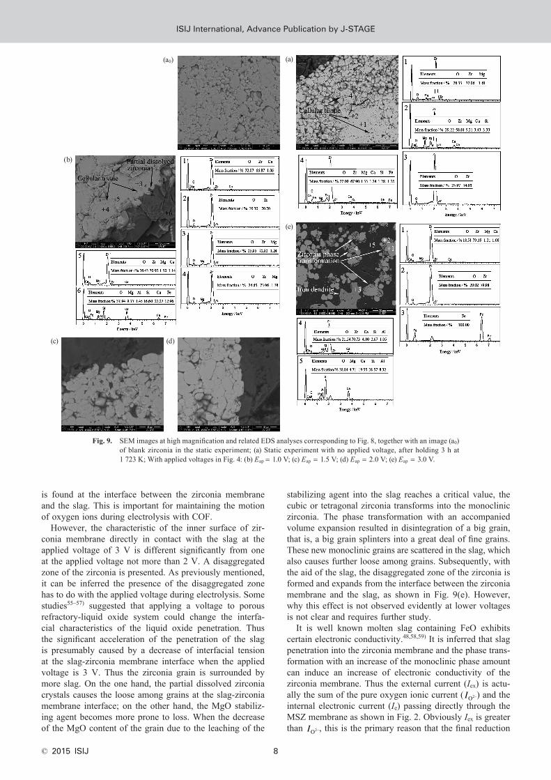
Figure 9 shows SEM images at high magnification and related EDS analyses corresponding to Fig. 8, together with an image of blank zirconia taken from the upper part of the zirconia tube without being exposed to the slag in the static experiment. The image of blank zirconia is described as Fig. 9(a0). It can be seen in Fig. 9(a0) the zirconia microstructure is characterized by the presence of big and small grains. In addition, there are also some microscopic pores. On the whole, small grains evenly distribute around big grains. The EDS analyses show the big grain contains Zr, O and a small amount of Mg elements, indicating MgO has solubilized in ZrO2 grain and a cubic solid solution is formed. Hence the big grain is attributed to cubic or tetragonal zirconia. But the small grain contains Zr and O elements and is
attributed to tetragonal or monoclinic zirconia with trace or no MgO. In Fig. 9(a), the zirconia microstructure still consists of big and small grains. The small grain remains unchanged. However, the big grain has changed a little, and cellular tissue can be observed in the big grain, especially in its periphery. The cellular tissue contains Si, Ca, Fe etc. besides Zr and O elements, but the central part of some bigger grains still contains Zr, O and Mg elements. These results indicate SiO2, CaO, FeO, and/or MgO components in the slag have penetrated into the zirconia membrane via grain boundaries and microscopic pores, where they interact with the big grains from the grain boundaries to the centers and the cellular tissue is formed in the big grains. Similar cellular tissue can also be found in the zirconia grain after the electrolysis experiments with different applied voltages, as shown in Figs. 8 and 9(b)–9(e). In fact, the interaction is on draining the MgO stabilizing agent out of the zirconia grain, which induces a phase transformation of the zirconia grain from the cubic or tetragonal phase into the monoclinic phase. The phase transformation phenomenon in stabilized zirconia based ceramics has also been observed by several researchers and may be considered as the most important cause of ceramics corrosion in slag.52–54) Therefore, one of the corrosion processes of zirconia membrane in this work can be described: the slag penetration into the zirconia mem-brane, the leaching of the MgO stabilizing agent from the cubic into the slag and transformation of exposed grains to monoclinic zirconia. Besides, the partial dissolved zirconia crystals can be observed at the interface between the zir-conia membrane and the slag, and the corresponding grain shows an irregular shape with a serrated border, as shown typically in Fig. 9(b). This can be considered as another cor-rosion process in this work. This corrosion is more likely to occur in slag with high FeO content. No interfacial product
Fig. 8. SEM images at low magnification of the interface between ZrO2 and slag after electrolysis with different applied voltages (a) Static experiment with no applied voltage, after holding 3 h at 1 723 K; With applied voltages in Fig. 4: (b) Eap = 1.0 V; (c) Eap = 1.5 V; (d) Eap = 2.0 V; (e) Eap = 3.0 V.
(a) (b) (c)
(d) (e)
ISIJ International, Advance Publication by J-StageISIJ International, Advance Publication by J-STAGE
ISIJ International, Vol. 55 (2015), No. 10
© 2015 ISIJ 8
is found at the interface between the zirconia membrane and the slag. This is important for maintaining the motion of oxygen ions during electrolysis with COF.
However, the characteristic of the inner surface of zir-conia membrane directly in contact with the slag at the applied voltage of 3 V is different significantly from one at the applied voltage not more than 2 V. A disaggregated zone of the zirconia is presented. As previously mentioned, it can be inferred the presence of the disaggregated zone has to do with the applied voltage during electrolysis. Some studies55–57) suggested that applying a voltage to porous refractory-liquid oxide system could change the interfa-cial characteristics of the liquid oxide penetration. Thus the significant acceleration of the penetration of the slag is presumably caused by a decrease of interfacial tension at the slag-zirconia membrane interface when the applied voltage is 3 V. Thus the zirconia grain is surrounded by more slag. On the one hand, the partial dissolved zirconia crystals causes the loose among grains at the slag-zirconia membrane interface; on the other hand, the MgO stabiliz-ing agent becomes more prone to loss. When the decrease of the MgO content of the grain due to the leaching of the
stabilizing agent into the slag reaches a critical value, the cubic or tetragonal zirconia transforms into the monoclinic zirconia. The phase transformation with an accompanied volume expansion resulted in disintegration of a big grain, that is, a big grain splinters into a great deal of fine grains. These new monoclinic grains are scattered in the slag, which also causes further loose among grains. Subsequently, with the aid of the slag, the disaggregated zone of the zirconia is formed and expands from the interface between the zirconia membrane and the slag, as shown in Fig. 9(e). However, why this effect is not observed evidently at lower voltages is not clear and requires further study.
It is well known molten slag containing FeO exhibits certain electronic conductivity.48,58,59) It is inferred that slag penetration into the zirconia membrane and the phase trans-formation with an increase of the monoclinic phase amount can induce an increase of electronic conductivity of the zirconia membrane. Thus the external current (Iex) is actu-ally the sum of the pure oxygen ionic current ( IO2−) and the internal electronic current (Ie) passing directly through the MSZ membrane as shown in Fig. 2. Obviously Iex is greater than IO2−, this is the primary reason that the final reduction
Fig. 9. SEM images at high magnification and related EDS analyses corresponding to Fig. 8, together with an image (a0) of blank zirconia in the static experiment; (a) Static experiment with no applied voltage, after holding 3 h at 1 723 K; With applied voltages in Fig. 4: (b) Eap = 1.0 V; (c) Eap = 1.5 V; (d) Eap = 2.0 V; (e) Eap = 3.0 V.
(a)
(e)
(b)
(c) (d)
(a0)
ISIJ International, Advance Publication by J-StageISIJ International, Advance Publication by J-STAGE

ISIJ International, Vol. 55 (2015), No. 10
© 2015 ISIJ9
ratio of FeO calculated by the Eq. (18) is excessively high in Fig. 7 when the applied voltage is 1.5 V. It should be noted that Ie could not be measured directly in real time, and does not have the reduction function yet.
Since the integrity of the zirconia microstructure is held, as shown in Fig. 8, it is considered acceptable the zirconia membrane serves an oxygen producing and relatively non-corrosive anode material in electrolysis process with COF if the applied voltage value does not exceed 2 V. In order to obtain metallic iron and minimize the corrosion of the molten slag to the zirconia membrane under the condition of this experiment, the applied voltage of 1.5 V seems to be advisable although higher the applied voltage is helpful to the FeO electrolytic reduction. However, it should be noted that the zirconia phase transformation caused by the molten slag not only leads to membrane degradation, but it also decreases process efficiency, which is adverse to electrolysis.
5. Conclusions
(1) The decomposition voltage of FeO in SiO2–CaO–MgO–Al2O3 slag was measured using the constructed electrolytic cell with COF by the linear sweep voltammetry at 1 723 K. The results show that decreased oxygen par-tial pressure in anode atmosphere can contribute to lower decomposition voltage of FeO in the slag.
(2) Under the same conditions, higher the applied volt-age leads to better electroreduction effect of FeO in the molten slag. With the applied voltage not more than 1.5 V, electrolytic product is pure metallic iron, and iron dendrite is formed. With the applied voltage not less than 2 V, elec-trolytic product is ferrosilicon, and iron dendrite is broken.
(3) Typical degradation mechanisms of the zirconia membrane such as the leaching of the stabilizing agent into the slag and partial dissolution of zirconia grain are observed in this work. The phase transformation of zirconia grain and the slag penetration can induce an increase of electronic conductivity of the zirconia membrane. The corrosion of the molten slag to the zirconia membrane during electrolysis is evidently aggravated by large the applied voltage.
(4) In order to obtain pure metallic iron and minimize the corrosion of the molten slag to the zirconia membrane, the applied voltage of 1.5 V is advisable.
AcknowledgementThe authors acknowledge the project funds provided
by the National Natural Science Foundation of China (No.51174148).
REFERENCES
1) Y. Tian, Q. Zhu and Y. Geng: Energ. Policy, 56 (2013), 352.2) W. Sun, J. Cai, H. Mao and D. Guan: J. Iron Steel Res. Int., 18
(2011), 31.3) D. Wang, A. Gmitter and D. Sadoway: J. Electrochem. Soc., 158
(2011), E51.4) H. Kim, J. Paramore, A. Allanore and D. Sadoway: J. Electrochem.
Soc., 158 (2011), E101.5) A. Sirk, D. Sadoway and L. Sibille: ECS Trans., 28 (2010), 367.6) A. Allanore, L. Yin and D. Sadoway: Nature, 497 (2013), 353.7) A. Allanore: Electrochim. Acta, 110 (2013), 587.8) Y. Gao, Y. Jiang, H. Zhang, X. Guo and K. Chou: J. Wuhan Univ.
Technol., 30 (2007), 449.
9) U. Pal and A. Powell IV: JOM, 59 (2007), 44.10) A. Krishnan, U. Pal and X. Lu: Metall.Mater. Trans. B, 36 (2005),
463.11) S. Britten and U. Pal: Metall. Mater. Trans. B, 31 (2000), 733.12) E. Gratz, X. Guan, J. Milshtein, U. Pal and A. Powell: Metall. Mater.
Trans. B, 45 (2014), 1325.13) X. Guan, P. Zink, U. Pal and A. Powell: Metall. Mater. Trans. B, 44
(2013), 261.14) X. Guan, U. Pal and A. Powell: Metall. Mater. Trans. E, 1 (2014),
132.15) Y. Gao, X. Guo and K. Chou: J. Univ. Sci. Technol. Beijing, 11
(2004), 306.16) Y. Gao, B. Wang, S. Wang and S. Peng: J. Min. Metall. B, 49 (2013),
49.17) C. Z. Wang: Solid Electrolyte and Chemical Sensors, Metallurgical
Industry Press, Beijing, (2000), 214.18) S. Tu and D. Janke: ISIJ Int., 35 (1995), 1362.19) G. Li and H. Suito: ISIJ Int., 37 (1997), 762.20) M. Iwase and T. Mori: Trans. Iron Steel Inst. Jpn., 19 (1979), 126.21) D. Fray: Metall. Mater. Trans. B, 34 (2003), 589.22) A. Weyl, S. Tu and D. Janke: Steel Res., 65 (1994), 167.23) T. Oishi, T. Goto, Y. Kayahara, K. Ono and J. Moriyama: Metall.
Trans. B, 13 (1982), 423.24) S. Yamashita, H. Fujiwara, E. Ichise and M. Iwase: Iron Steelmaker,
19 (1992), 57.25) T. Ogura, R. Fujiwara, R. Mochizuki, Y. Kawamoto, T. Oishi and M.
Iwase: Metall. Trans. B, 23 (1992), 459.26) M. Iwase, T. Ogura and R. Tsujino: Steel Res., 65 (1994), 90.27) M. Van Wijingaarden, R. Dippenaar and P. Van den Heever: J. S.
Afr. Inst. Min. Metall., 87 (1987), 269.28) E. Turkdogan: Ironmaking Steelmaking, 27 (2000), 32.29) K. Oberg, L. Friedman, W. Boorstein and R. Rapp: Metall. Trans., 4
(1973), 61.30) K. Oberg, L. Friedman, R. Szwarc, W. Boorstein and R. Rapp: J. Iron
Steel Inst., 210 (1972), 359.31) R. Ganesan, T. Gnanasekaran and R. S. Srinivasa: J. Nucl. Mater.,
349 (2006), 133.32) Y. Gao, J. Song, Y. Zhang and X. Guo: Acta Metall. Sin., 46 (2010),
277.33) K. Oberg, L. Friedman, W. Boorstein and R. Rapp: Metall. Trans., 4
(1973), 75.34) P. Soral, U. Pal, H. Larson and B. Schroeder: Metall. Mater. Trans.
B, 30 (1999), 307.35) W. Fischer and D. Janke: Scr. Metall., 6 (1972), 923.36) R. Odle and R. Rapp: Metall. Trans. B, 8 (1977), 581.37) M. Iwase, M. Tanida, A. Mclean and T. Mori: Metall. Trans. B, 12
(1981), 517.38) Z. Hasham, U. Pal and K. Chou: J. Electrochem. Soc., 142 (1995),
469.39) S. Yuan, U. Pal and K. Chou: J. Am. Ceram. Soc., 79 (1996), 641.40) W. Kim and I. Sohn: ISIJ Int., 51 (2011), 63.41) W. Kim and D. Min: Steel Res. Int., 82 (2011), 195.42) H. Koo, H. Park, G. Choi and H. Lee: ISIJ Int., 47 (2007), 689.43) W. Kim, D. Min, Y. Lee and J. Park: ISIJ Int., 49 (2009), 1882.44) X. Lu, X. Zou, C. Li, Q. Zhong, W. Ding and Z. Zhou: Metall. Mater.
Trans. B, 43 (2012), 503.45) A. Martin, J. Poignet, J. Fouletier, M. Allibert, D. Lambertin and G.
Bourgès: J. Appl. Electrochem., 40 (2010), 533.46) E. Franks: J. Appl. Electrochem., 7 (1977), 147.47) C. Bale, E. Bélisle, P. Chartrand, S. Decterov, G. Eriksson, K. Hack,
I. Jung, Y. Kang, J. Melançon, A. Pelton, C. Robelin and S. Petersen: Calphad, 33 (2009), 295.
48) K. Goto: Proc. 2nd Int. Symp. on Metallurgical Slags and Fluxes, Trans. Metall. Soc. AIME, Warrendale, PA, (1984), 839.
49) Y. Gao, K. Chou, X. Guo and W. Wang: J. Iron Steel Res. Int., 14 (2007), 16.
50) C. Z. Wang: Solid Electrolyte and Chemical Sensors, Metallurgical Industry Press, Beijing, (2000), 240.
51) J. Q. Yu, W. Z. Yi, B. D. Chen and H. J. Chen: Binary Alloy Phase Diagrams, Shanghai Science and Technology Press, Shanghai, (1987), 375.
52) Y. Chung and M. Schlesinger: J. Am. Ceram. Soc., 77 (1994), 611.53) C. Aneziris, E. Pfaff and H. Maier: J. Eur. Ceram. Soc., 20 (2000),
159.54) Y. Hemberger, C. Berthold and K. Nickel: J. Eur. Ceram. Soc., 32
(2012), 2859.55) R. K. Sauerbrey, G. Mori, C. Majcenovic and H. Harmuth: Corros.
Sci., 51 (2009), 1.56) S. Riaz, K. C. Mills and K. Bain: Ironmaking Steelmaking, 29 (2002),
107.57) B. J. Monaghan, S. A. Nightingale, Q. Dong and M. Funcik: Engi-
neering, 2 (2010), 496.58) M. Barati and K. S. Coley: Metall. Mater. Trans. B, 37 (2006), 41.59) M. Barati and K. S. Coley: Metall. Mater. Trans. B, 37 (2006), 51.
ISIJ International, Advance Publication by J-StageISIJ International, Advance Publication by J-STAGE

ISIJ International, Vol. 55 (2015), No. 10
© 2015 ISIJ 10
AppendixTable of Symbols
Symbol Definition
A area of electrode or slag/ZrO2 interface
ai activity of i species
B slag basicity, B = CaO mass% / SiO2 mass%
Cbi , Ci
i bulk and interfacial concentration of i species in slag, respectively
Di diffusion coefficient of i species in slag
Eap applied voltage between cathode and anode
En Nernst voltage established between cathode and anode
F the Faraday constant, F = 96 500 C/mol
FeO mass mass fraction of FeO in slag, FeO mass = 10%
ΔG0 standard Gibbs free-energy change
ΔG Gibbs free-energy change
Ie internal electronic current flowing through MSZ membrane
IO2− oxygen ionic current flowing through electrolytic cell
Iex external current
Ji individual flux of i species (such as Fe2+ and O2−)
MFeO the molar mass of FeO, MFeO = 72 g/mol
mslag mass of slag, mslag = 3.7 g
n number of electrons exchanged in the reaction, n = 2
pO anode2 ( ) oxygen partial pressure in anode atmosphere
R the gas constant
Rct charge transfer resistance at cathode and anode
Rex resistance of electrodes and lead wires
Rmt mass transfer resistance at cathode and anode
Rohmic total ohmic resistance in circuit
Rslagi ionic resistance of slag
Rslage electronic resistance of slag
RZrOi
2ionic resistance of MSZ membrane
RZrOe
2electronic resistance of MSZ membrane
T absolute temperature
t reduction time, s
δi boundary layer corresponding to i species
ηFeO reduction ratio of FeO in slag, %
ISIJ International, Advance Publication by J-StageISIJ International, Advance Publication by J-STAGE