Determination of Voltage Regulation
12
Determination of Voltage Regulation The following are the three methods which are used to determine the voltage regulation of smooth cylindrical type Alternators 1. Synchronous impedance / EMF method 2. Ampere-turn / MMF method 3. Potier / ZPF method 1. Synchronous impedance / EMF method Synchronous impedance is calculated from OCC and SCC as Zs = Ea/Isc(for same If) A compromised value of Zs is normally estimated by taking the ratio of (Ea/Isc) at normal field current If. A normal field current If is one which gives rated voltage V on open circuit. Zs = V/Isc Advantages: • Simple no load tests (for obtaining OCC and SCC) are to be conducted • Calculation procedure is much simpler Disadvantages: • The value of voltage regulation obtained by this method is always higher than the actual value.
-
Upload
khangminh22 -
Category
Documents
-
view
7 -
download
0
Transcript of Determination of Voltage Regulation

Determination of Voltage Regulation
The following are the three methods which are used to determine the voltage regulation of smooth
cylindrical type Alternators
1. Synchronous impedance / EMF method
2. Ampere-turn / MMF method
3. Potier / ZPF method
1. Synchronous impedance / EMF method
Synchronous impedance is calculated from OCC and SCC as Zs = Ea/Isc(for same If)
A compromised value of Zs is normally estimated by taking the ratio of (Ea/Isc) at normal field current If. A
normal field current If is one which gives rated voltage V on open circuit.
Zs = V/Isc
Advantages:
• Simple no load tests (for obtaining OCC and SCC) are to be conducted • Calculation procedure is much
simpler
Disadvantages:
• The value of voltage regulation obtained by this method is always higher than the actual value.

2. Ampere-turn / MMF method
The ampere-turn /MMF method is the converse of the EMF
method in the sense that instead of having the phasor addition of
various voltage drops/EMFs, here the phasor addition of MMF
required for the voltage drops are carried out. Further the effect
of saturation is also taken care of.
Data required for MMF method are:
• Effective resistance per phase of the 3-phase winding R
• Open circuit characteristic (OCC) at rated speed/frequency
• Short circuit characteristic (SCC) at rated speed/frequency

Compared to the EMF method, MMF method, involves more number of complex
calculation steps. Further the OCC is referred twice and SCC is referred once while
predetermining the voltage regulation for each load condition. Reference of OCC
takes care of saturation effect. As this method requires more effort, the final result is
very close to the actual value. Hence this method is called optimistic method.

SSyynncchhrroonnoouuss GGeenneerraattoorrss Dr. SSuuaadd IIbbrraahhiimm SShhaahhll
29
1
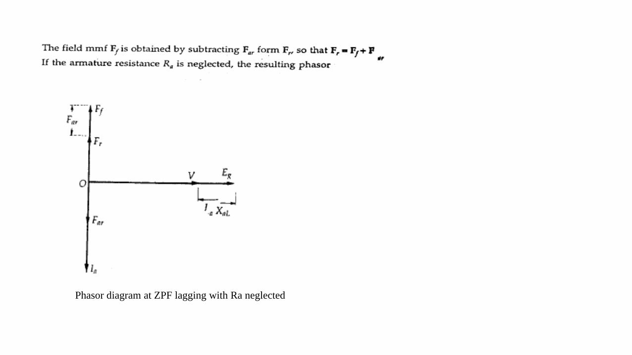
Phasor diagram at ZPF lagging with Ra neglected
SSyynncchhrroonnoouuss GGeenneerraattoorrss Dr. SSuuaadd IIbbrraahhiimm SShhaahhll
29
1
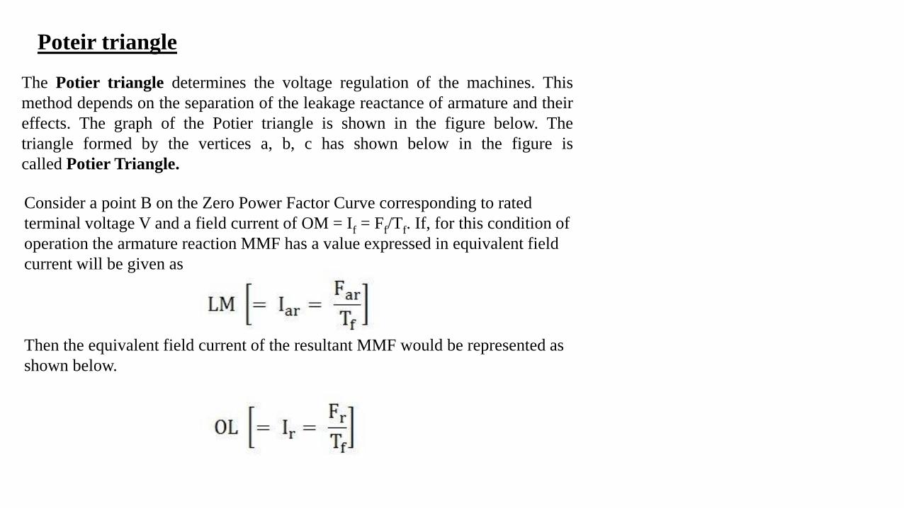
The Potier triangle determines the voltage regulation of the machines. This
method depends on the separation of the leakage reactance of armature and their
effects. The graph of the Potier triangle is shown in the figure below. The
triangle formed by the vertices a, b, c has shown below in the figure is
called Potier Triangle.
Poteir triangle
Consider a point B on the Zero Power Factor Curve corresponding to rated
terminal voltage V and a field current of OM = If = Ff/Tf. If, for this condition of
operation the armature reaction MMF has a value expressed in equivalent field
current will be given as
Then the equivalent field current of the resultant MMF would be represented as
shown below.


This field current OL would result in a generated voltage Eg = Lc from the no-
load saturation curve. Since for lagging Zero Power Factor operation, the
generated voltage will be
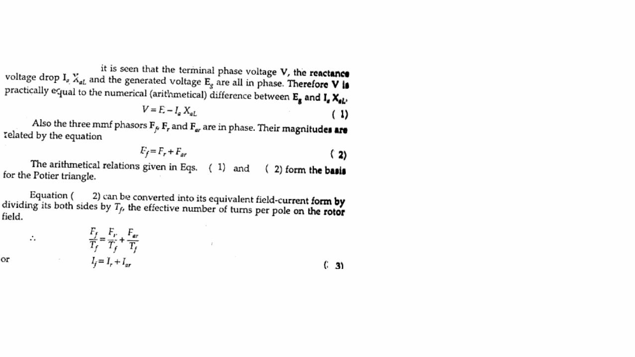
The vertical distance ac must be equal to the leakage reactance voltage
DROP IaXaL where Ia is the rated armature current.
Therefore,

For Zero Power Factor operation with rated current at any other terminal
voltage, such as V2. As the armature current is of the same value, both the Ia and
XaL voltage and the armature MMF must be of the same value. Therefore, for all
the conditions of operation with rated armature current at zero lagging power
factor, the Potier Triangle must be located between the terminal voltage V, a point
on the ZPFC and the corresponding Eg point on the O.C.C.
If the Potier triangle cab is moved downward so that the side ab is kept horizontal
and b is kept on the ZPFC, the point c will move on the O.C.C. When the point b,
reaches the point e, the Potier triangle cab will move on the position fde shown in
the figure. The location of point f on the O.C.C will determine the voltage Eg2.
When the point b, reaches the point b`, the Potier Triangle will be in the position
c`a`b`. This is the limiting position which corresponds to short the circuit
condition because the terminal voltage is zero at the point b`.
The initial part of the O.C.C is almost linear, another triangle Oc`b`is formed by
the O.C.C. The hypotenuse of the Potier triangle and the baseline. A similar
triangle such as ckb, can construct from the Potier triangle in any other location
by drawing a line kc parallel to Oc`.

Steps for Construction of Potier Triangle on ZPFC
•Take a point b on the ZPFC preferably well upon the knee of the curve.
•Draw bk equal to b`O. (b` is the point for zero voltage, full load current). Ob` is the short circuit excitation Fsc.
•Through k draw, kc parallel to Oc` to meet O.C.C in c.
•Drop the perpendicular ca on to bk.
•Then, to scale ca is the leakage reactance drop IaXaL and ab is the armature reaction MMF FaR or the field current
IfaR equivalent to armature reaction MMF at rated current.
The effect of field leakage flux in combination with the armature leakage flux gives rise to an equivalent leakage
reactance Xp, known as the Potier Reactance. It is greater than the armature leakage reactance.
For cylindrical rotor machines, the Potier reactance Xp is approximately equal to the leakage reactance XaL. in
salient pole machine, Xp may be as large as 3 times XaL.

Assumptions for Potier Triangle
The following assumptions are made in the Potier Triangle
Method. They are as follows:-
•The armature resistance Ra is neglected.
•The O.C.C taken on no load accurately represents the relation
between MMF and Voltage on load.
•The leakage reactance voltage Ia XaL is independent of
excitation.
•The armature reaction MMF is constant.
It is not necessary to plot the entire ZPFC for determining
XaL and Fa, only two points b and b ` are sufficient. Point b
corresponds to a field current which gives the rated terminal
voltage while the ZPF load is adjusted to draw rated current.
Point b ` corresponds to the short circuit condition (V = 0) on
the machine. Thus, Ob ` is the field current required to circulate
the short circuit current equal to the rated current.