
Nassiuma Thesis 2018 .pdf - Moi University Institutional ...
Upload
khangminh22Category
view
0download
0
A METHODOLOGY TO SUPPORT RELEVANT COMPARISONS OFEARTH-MARS COMMUNICATION ARCHITECTURES
A ThesisPresented to
The Academic Faculty
By
Florence B. Duveiller
In Partial Fulfillmentof the Requirements for the Degree
Master of Science in theThe Guggenheim School of Aerospace Engineering
Georgia Institute of Technology
December 2018
Copyright © Florence B. Duveiller 2018

A METHODOLOGY TO SUPPORT RELEVANT COMPARISONS OFEARTH-MARS COMMUNICATION ARCHITECTURES
Approved by:
Prof. Dimitri N. Mavris, AdvisorSchool of Aerospace EngineeringGeorgia Institute of Technology
Dr. Olivia J. Pinon FischerSchool of Aerospace EngineeringGeorgia Institute of Technology
Prof. Brian C. GunterSchool of Aerospace EngineeringGeorgia Institute of Technology
Date Approved: November 30, 2018

We choose to go to the moon in this decade and do the other things, not because they are
easy, but because they are hard, because that goal will serve to organize and measure the
best of our energies and skills, because that challenge is one that we are willing to accept,
one we are unwilling to postpone, and one which we intend to win, and the others, too.
– John F. Kennedy (Rice University, September 12, 1962)

A Bon-papa †
A mes frères, Vincent et Alexandre

ACKNOWLEDGEMENTS
The end of this master thesis concludes the American episode of my life. It is time for
me to thank all the people who have been there with me along the way, to guide me and
believe in myself, helping me to grow up.
My first thanks go to my advisor, Dr. Dimitri Mavris, for his insight on my work and
his wise advice on this thesis and on my career in general, for finding the time and for
being so supportive. I am very grateful for having had an advisor who truly cares. Then,
I would like to thank Dr. Olivia Pinon-Fischer for her guidance and support throughout
this process. Olivia, I really appreciate your constant commitment towards my research.
Thank you for understanding and helping me as much as you can. Lastly, I would like to
thank Dr. Brian Gunter for his expert eye on this work. I would probably not have oriented
my career towards space without his orbital mechanics class during my first semester at
GeorgiaTech. I also would like to acknowledge Dr. Burak Bagdatli for his encouragements
and for proofreading this document.
This document also closes my school years, at least for a while. This is why, I would
like to express my gratitude to the people who have crossed my path during all those years
and who made me become the woman I am today. I would like to especially thank Laurent
Sallen for shaping my scientific rigor and for his support during the most demanding years
of my education. My gratitude also goes to the Ecole polytechnique including the military
staff, for giving me the opportunity to experiment and deepen my knowledge. As André
Malraux said "Between the ages of 18 and 20, life is like a market where you buy values
not with money, but with deeds. Most men do not buy anything". I owe my human skills
to the X and to the scouting.
I cannot close this page without acknowledge my true friends on the old continent,
Lorenzo, Camille, Cécile and Christian. Thank you for always picking up the phone even
when I had not given any news for months. I promise it will be better when I will be back.
v

I also would like to thank my friends from Ecole polytechnique, you are like family to me,
and the scout team, I cannot wait to go camping with you again. Finally, living far from
home is not always easy. I would like to thank the friends I made here who enlightened this
journey; the French squad, Luis and Colby, Yann, Etienne.
Last but not least, my deepest thanks go to my two cornerstones in this Georgia Tech
adventure, Manon and Jérôme. I would not be here today without you. Manon, thank
you for sharing the experience of the thesis from the beginning to the end with me, for
sharing the desk and even more. Jérôme, the discussions we had around this research
helped pushing it forward. Thank you for the help you provided me, in implementing the
architectures and in proofreading this document, and for your keen and watchful eye on my
work. Your optimism and your confidence have carried me on this path strewn with doubts.
vi

TABLE OF CONTENTS
Acknowledgments . . . . . . . . . . . . . . . . . . . . . . . . . . . . . . . . . . . v
List of Tables . . . . . . . . . . . . . . . . . . . . . . . . . . . . . . . . . . . . . . xiii
List of Figures . . . . . . . . . . . . . . . . . . . . . . . . . . . . . . . . . . . . . xvi
Chapter 1: Motivation . . . . . . . . . . . . . . . . . . . . . . . . . . . . . . . . . 1
1.1 Why go to Mars . . . . . . . . . . . . . . . . . . . . . . . . . . . . . . . . 1
1.1.1 Scientific considerations . . . . . . . . . . . . . . . . . . . . . . . 3
1.1.2 Political considerations . . . . . . . . . . . . . . . . . . . . . . . . 4
1.1.3 Societal considerations . . . . . . . . . . . . . . . . . . . . . . . . 5
1.1.4 Economic considerations . . . . . . . . . . . . . . . . . . . . . . . 6
1.1.5 When ? . . . . . . . . . . . . . . . . . . . . . . . . . . . . . . . . 7
1.2 Why communications are needed . . . . . . . . . . . . . . . . . . . . . . . 9
1.2.1 Communication systems, an enabler for crewed missions to Mars . . 9
1.2.2 Challenges . . . . . . . . . . . . . . . . . . . . . . . . . . . . . . 11
1.2.3 Impacts and benefits . . . . . . . . . . . . . . . . . . . . . . . . . 14
1.3 Summary . . . . . . . . . . . . . . . . . . . . . . . . . . . . . . . . . . . 17
Chapter 2: Background and Gaps Identification . . . . . . . . . . . . . . . . . . 19
vii

2.1 Communication technologies . . . . . . . . . . . . . . . . . . . . . . . . . 20
2.1.1 Radiofrequency . . . . . . . . . . . . . . . . . . . . . . . . . . . . 20
2.1.2 Optical communications . . . . . . . . . . . . . . . . . . . . . . . 20
2.1.3 Comparison . . . . . . . . . . . . . . . . . . . . . . . . . . . . . . 22
2.1.4 Faster-than-Light communications . . . . . . . . . . . . . . . . . . 24
2.2 Interplanetary Internet . . . . . . . . . . . . . . . . . . . . . . . . . . . . . 25
2.3 Communication architectures . . . . . . . . . . . . . . . . . . . . . . . . . 28
2.3.1 Traditional architecture . . . . . . . . . . . . . . . . . . . . . . . . 29
2.3.2 Martian constellations . . . . . . . . . . . . . . . . . . . . . . . . 30
2.3.3 Satellites in heliocentric orbit . . . . . . . . . . . . . . . . . . . . . 32
2.3.4 Summary . . . . . . . . . . . . . . . . . . . . . . . . . . . . . . . 36
2.4 Methodological Gaps Identification . . . . . . . . . . . . . . . . . . . . . . 37
2.4.1 Incompleteness of comparisons . . . . . . . . . . . . . . . . . . . . 38
2.4.2 Uncertainty on requirements . . . . . . . . . . . . . . . . . . . . . 39
2.4.3 Discrepancy in the impact of a technology choice . . . . . . . . . . 41
2.4.4 Summary . . . . . . . . . . . . . . . . . . . . . . . . . . . . . . . 41
Chapter 3: Problem Definition . . . . . . . . . . . . . . . . . . . . . . . . . . . . 44
3.1 Research Scope . . . . . . . . . . . . . . . . . . . . . . . . . . . . . . . . 44
3.1.1 Conceptual design . . . . . . . . . . . . . . . . . . . . . . . . . . 44
3.1.2 Communication-centered analysis . . . . . . . . . . . . . . . . . . 45
3.1.3 Existing technologies . . . . . . . . . . . . . . . . . . . . . . . . . 47
3.1.4 Operation phase . . . . . . . . . . . . . . . . . . . . . . . . . . . . 48
viii

3.1.5 Radiofrequency . . . . . . . . . . . . . . . . . . . . . . . . . . . . 48
3.2 Decomposition of the objective . . . . . . . . . . . . . . . . . . . . . . . . 50
3.3 The requirements . . . . . . . . . . . . . . . . . . . . . . . . . . . . . . . 52
3.3.1 Requirements definition . . . . . . . . . . . . . . . . . . . . . . . . 53
3.3.2 Mapping techniques . . . . . . . . . . . . . . . . . . . . . . . . . . 54
3.3.3 Hypothesis . . . . . . . . . . . . . . . . . . . . . . . . . . . . . . 63
3.4 Implementation of the architectures . . . . . . . . . . . . . . . . . . . . . . 65
3.4.1 A physics-based approach . . . . . . . . . . . . . . . . . . . . . . 65
3.4.2 Hypothesis . . . . . . . . . . . . . . . . . . . . . . . . . . . . . . 67
3.4.3 Modeling and simulation environments . . . . . . . . . . . . . . . 68
3.5 Evaluation and ranking . . . . . . . . . . . . . . . . . . . . . . . . . . . . 71
3.5.1 Decision-making techniques . . . . . . . . . . . . . . . . . . . . . 71
3.5.2 Hypothesis . . . . . . . . . . . . . . . . . . . . . . . . . . . . . . 77
3.6 Summary . . . . . . . . . . . . . . . . . . . . . . . . . . . . . . . . . . . 79
Chapter 4: Methodology Formulation . . . . . . . . . . . . . . . . . . . . . . . . 81
4.1 Methodology overview . . . . . . . . . . . . . . . . . . . . . . . . . . . . 81
4.2 Step 1: Mapping the requirements . . . . . . . . . . . . . . . . . . . . . . 82
4.3 Step 2: Building the framework . . . . . . . . . . . . . . . . . . . . . . . . 83
4.4 Step 3: Ranking the architectures . . . . . . . . . . . . . . . . . . . . . . . 85
Chapter 5: STEP 1 - Mapping the requirements . . . . . . . . . . . . . . . . . . 87
5.1 Definition of the requirements in past studies . . . . . . . . . . . . . . . . . 87
5.2 Review of the requirements for an Earth-Mars communication architecture . 90
ix

5.2.1 Presentation . . . . . . . . . . . . . . . . . . . . . . . . . . . . . . 90
5.2.2 The review . . . . . . . . . . . . . . . . . . . . . . . . . . . . . . 91
5.2.3 Summary . . . . . . . . . . . . . . . . . . . . . . . . . . . . . . . 96
5.3 Requirements mapping . . . . . . . . . . . . . . . . . . . . . . . . . . . . 97
5.3.1 Definition . . . . . . . . . . . . . . . . . . . . . . . . . . . . . . . 97
5.3.2 Mapping . . . . . . . . . . . . . . . . . . . . . . . . . . . . . . . . 99
5.4 Validation . . . . . . . . . . . . . . . . . . . . . . . . . . . . . . . . . . . 102
Chapter 6: STEP 2 - Building the framework . . . . . . . . . . . . . . . . . . . . 104
6.1 Building the framework . . . . . . . . . . . . . . . . . . . . . . . . . . . . 104
6.1.1 The environment . . . . . . . . . . . . . . . . . . . . . . . . . . . 104
6.1.2 The architectures . . . . . . . . . . . . . . . . . . . . . . . . . . . 106
6.2 Defining the metrics . . . . . . . . . . . . . . . . . . . . . . . . . . . . . . 107
6.2.1 Link availability . . . . . . . . . . . . . . . . . . . . . . . . . . . . 107
6.2.2 Coverage . . . . . . . . . . . . . . . . . . . . . . . . . . . . . . . 109
6.2.3 Propagation delay . . . . . . . . . . . . . . . . . . . . . . . . . . . 109
6.2.4 Number of elements . . . . . . . . . . . . . . . . . . . . . . . . . 110
6.2.5 Data rate . . . . . . . . . . . . . . . . . . . . . . . . . . . . . . . . 111
6.3 Validating the framework . . . . . . . . . . . . . . . . . . . . . . . . . . . 112
6.3.1 IRIS Test case . . . . . . . . . . . . . . . . . . . . . . . . . . . . . 112
6.3.2 MarsWeb Test case . . . . . . . . . . . . . . . . . . . . . . . . . . 115
6.4 The architectures survey . . . . . . . . . . . . . . . . . . . . . . . . . . . 121
6.4.1 Martian constellations . . . . . . . . . . . . . . . . . . . . . . . . 122
x

6.4.2 Heliocentric concepts . . . . . . . . . . . . . . . . . . . . . . . . . 129
6.4.3 Relays . . . . . . . . . . . . . . . . . . . . . . . . . . . . . . . . . 131
6.4.4 Mixed architectures . . . . . . . . . . . . . . . . . . . . . . . . . . 137
6.5 Validation . . . . . . . . . . . . . . . . . . . . . . . . . . . . . . . . . . . 137
Chapter 7: STEP 3 - Ranking the architectures . . . . . . . . . . . . . . . . . . . 139
7.1 Evaluation of the architectures . . . . . . . . . . . . . . . . . . . . . . . . 139
7.1.1 Evaluation . . . . . . . . . . . . . . . . . . . . . . . . . . . . . . . 139
7.1.2 Results by criterion . . . . . . . . . . . . . . . . . . . . . . . . . . 141
7.2 Weighting scenarios . . . . . . . . . . . . . . . . . . . . . . . . . . . . . . 145
7.3 Ranking the alternatives . . . . . . . . . . . . . . . . . . . . . . . . . . . . 147
7.3.1 Scenario 1 . . . . . . . . . . . . . . . . . . . . . . . . . . . . . . . 149
7.3.2 Scenario 2 . . . . . . . . . . . . . . . . . . . . . . . . . . . . . . . 150
7.3.3 Scenario 3 . . . . . . . . . . . . . . . . . . . . . . . . . . . . . . . 151
7.3.4 Scenario 4 . . . . . . . . . . . . . . . . . . . . . . . . . . . . . . . 153
7.3.5 Comparison of the results from the different scenarios . . . . . . . . 154
7.4 Validation . . . . . . . . . . . . . . . . . . . . . . . . . . . . . . . . . . . 156
Chapter 8: Conclusion . . . . . . . . . . . . . . . . . . . . . . . . . . . . . . . . 158
8.1 Summary . . . . . . . . . . . . . . . . . . . . . . . . . . . . . . . . . . . 158
8.2 Contributions . . . . . . . . . . . . . . . . . . . . . . . . . . . . . . . . . 162
8.2.1 The methodology . . . . . . . . . . . . . . . . . . . . . . . . . . . 162
8.2.2 The framework in STK . . . . . . . . . . . . . . . . . . . . . . . . 163
8.2.3 The requirements review . . . . . . . . . . . . . . . . . . . . . . . 163
xi

8.2.4 The architectures survey . . . . . . . . . . . . . . . . . . . . . . . 164
8.3 Future work . . . . . . . . . . . . . . . . . . . . . . . . . . . . . . . . . . 164
8.3.1 Implementing the communication technology and performing a sen-sitivity analysis . . . . . . . . . . . . . . . . . . . . . . . . . . . . 164
8.3.2 Implementing new architectures and performing optimization studies 165
8.3.3 Extending the set of requirements and testing other weighting sce-narios . . . . . . . . . . . . . . . . . . . . . . . . . . . . . . . . . 166
Appendix A: Architectures and their requirements . . . . . . . . . . . . . . . . 169
Appendix B: Requirements review . . . . . . . . . . . . . . . . . . . . . . . . . 175
Appendix C: Architectures survey . . . . . . . . . . . . . . . . . . . . . . . . . . 180
Appendix D: Results by scenario . . . . . . . . . . . . . . . . . . . . . . . . . . . 186
References . . . . . . . . . . . . . . . . . . . . . . . . . . . . . . . . . . . . . . . 199
xii

LIST OF TABLES
1.1 Relationship between the minimum angle and the frequency . . . . . . . . 13
2.1 Comparison between Optical communications and RF for relevant figuresof merit (FOM), the green check indicating the best option for each FOM . 23
2.2 Characteristics of several constellation design propositions . . . . . . . . . 31
2.3 Comparison between the different classes of communication architectures . 37
3.1 Description of Project Life Cycle Phases by NASA [55] . . . . . . . . . . . 49
3.2 Comparison between the different requirements mapping techniques . . . . 61
3.3 Comparison of the different modeling and simulation environments . . . . . 70
3.4 Characteristics of MCDM techniques . . . . . . . . . . . . . . . . . . . . . 75
5.1 Requirements for a deep-space communication architecture by NASA [76] . 93
5.2 Requirements and metrics by Bell [42] and Talbot-Stern [46] . . . . . . . . 95
5.3 Requirements mapping through a relationship matrix . . . . . . . . . . . . 102
6.1 Parameters in STK . . . . . . . . . . . . . . . . . . . . . . . . . . . . . . 105
6.2 Properties of the DSN antennas selected . . . . . . . . . . . . . . . . . . . 105
6.3 Orbital elements of the IRIS Test case . . . . . . . . . . . . . . . . . . . . 113
6.4 Orbital elements of the MarsWeb Test case . . . . . . . . . . . . . . . . . . 117
6.5 Orbital elements of the four-satellite network [90] . . . . . . . . . . . . . . 125
xiii

7.1 Mixed architectures added for the implementation . . . . . . . . . . . . . . 141
7.2 Results of the implementation and evaluation of the architectures . . . . . . 142
7.3 Ranking of the architectures by requirement . . . . . . . . . . . . . . . . . 143
7.4 Weighting scenarios . . . . . . . . . . . . . . . . . . . . . . . . . . . . . . 146
7.5 Ranking of all the alternatives by scenario . . . . . . . . . . . . . . . . . . 148
A.1 List of the architectures with the associated requirements . . . . . . . . . . 170
A.2 List of the architectures with the associated requirements (continued) . . . . 171
A.3 List of the architectures with the associated requirements (continued) . . . . 172
A.4 List of the architectures with the associated requirements (continued) . . . . 173
A.5 List of the architectures with the associated requirements (continued) . . . . 174
B.1 Requirements review . . . . . . . . . . . . . . . . . . . . . . . . . . . . . 176
B.2 Requirements review (continued) . . . . . . . . . . . . . . . . . . . . . . . 177
B.3 Requirements review (continued) . . . . . . . . . . . . . . . . . . . . . . . 178
B.4 Requirements review (continued) . . . . . . . . . . . . . . . . . . . . . . . 179
C.1 Architectures survey . . . . . . . . . . . . . . . . . . . . . . . . . . . . . . 181
C.2 Architectures survey (continued) . . . . . . . . . . . . . . . . . . . . . . . 182
C.3 Architectures survey (continued) . . . . . . . . . . . . . . . . . . . . . . . 183
C.4 Architectures survey (continued) . . . . . . . . . . . . . . . . . . . . . . . 184
C.5 Architectures survey (continued) . . . . . . . . . . . . . . . . . . . . . . . 185
D.1 Ranking of the architectures using the TOPSIS for the scenario 1 . . . . . . 187
D.2 Ranking of the architectures using the TOPSIS for the scenario 2 . . . . . . 188
xiv

D.3 Ranking of the architectures using the TOPSIS for the scenario 3 . . . . . . 189
D.4 Ranking of the architectures using the TOPSIS for the scenario 4 . . . . . . 190
xv

LIST OF FIGURES
1.1 Partial representation of the solar system to scale . . . . . . . . . . . . . . 2
1.2 Correlation between the NASA budget and the number of students follow-ing a PhD program in physical science, engineering and mathematics [3] . . 6
1.3 Superior solar conjunction on the left, Inferior solar conjunction on the right 12
1.4 Definition of the angles during a solar conjunction . . . . . . . . . . . . . . 13
1.5 Locations of DSN ground stations and the complete deep-space coverage[30] . . . . . . . . . . . . . . . . . . . . . . . . . . . . . . . . . . . . . . 16
1.6 Earth-Probe solar conjunction . . . . . . . . . . . . . . . . . . . . . . . . . 17
2.1 Decomposition of a communication system in this thesis . . . . . . . . . . 19
2.2 Wavelength Spectrum . . . . . . . . . . . . . . . . . . . . . . . . . . . . . 21
2.3 Comparison between RF and optical beams [35] . . . . . . . . . . . . . . . 21
2.4 Comparison of the performance of X-band, Ka-band and Optical commu-nications for a Mars mission in terms of mass, power and cost according tothe data volume in the worst case scenario of a Mars-Earth distance of 2.7AU . . . . . . . . . . . . . . . . . . . . . . . . . . . . . . . . . . . . . . . 22
2.5 A possible alternative of the Interplanetary Internet network [41] . . . . . . 26
2.6 Different types of concepts for Earth-Mars communication architectures . . 28
2.7 Traditional lander-orbiter configuration . . . . . . . . . . . . . . . . . . . . 29
2.8 Lagrange points in a Sun-Planet system . . . . . . . . . . . . . . . . . . . 34
xvi

2.9 Trade-off between the minimum distance to overcome the solar conjunctionissue (in grey) and to be close enough to Mars (in green) [48] . . . . . . . . 35
2.10 Impact of the modification of the minimum SEM angle on the location of arelay . . . . . . . . . . . . . . . . . . . . . . . . . . . . . . . . . . . . . . 42
3.1 Illustration of the design process [52] . . . . . . . . . . . . . . . . . . . . . 46
3.2 NASA Project Life Cycle Process Flow [55] . . . . . . . . . . . . . . . . . 48
3.3 Schema of the reduced problem . . . . . . . . . . . . . . . . . . . . . . . . 51
3.4 The new representation of the problem after mapping of the requirements . 51
3.5 Illustration of an interrelationship diagraph . . . . . . . . . . . . . . . . . . 55
3.6 Elements of a QFD matrix [58] . . . . . . . . . . . . . . . . . . . . . . . . 57
3.7 Cascading process of a QFD [58] . . . . . . . . . . . . . . . . . . . . . . . 57
3.8 Decomposition view for a specification tree . . . . . . . . . . . . . . . . . 58
3.9 Illustration of a specification tree . . . . . . . . . . . . . . . . . . . . . . . 59
3.10 Analytic Hierarchy Process example on a comparison between satellitesand airplanes [58] . . . . . . . . . . . . . . . . . . . . . . . . . . . . . . . 60
3.11 First Step of AHP: Defining criteria and alternatives . . . . . . . . . . . . . 61
3.12 Second step of AHP: the prioritization matrix for the requirements . . . . . 62
3.13 Final step of AHP: the results . . . . . . . . . . . . . . . . . . . . . . . . . 63
3.14 Classification of MCDM techniques . . . . . . . . . . . . . . . . . . . . . 74
3.15 One of the possible method to select a MCDM [68] . . . . . . . . . . . . . 76
3.16 Illustration of the computation of the distance from the PIS and NIS in theTOPSIS technique . . . . . . . . . . . . . . . . . . . . . . . . . . . . . . . 78
3.17 Evaluation matrix for the TOPSIS . . . . . . . . . . . . . . . . . . . . . . 79
3.18 Summary of the problem . . . . . . . . . . . . . . . . . . . . . . . . . . . 80
xvii

4.1 Generic top-down design decision support process . . . . . . . . . . . . . . 81
4.2 Evaluation matrix for the TOPSIS . . . . . . . . . . . . . . . . . . . . . . 85
5.1 Classification of requirements by the number of occurrence . . . . . . . . . 88
5.2 Value for the link availability requirement and the data rate requirement . . 89
5.3 Classification of requirements by Bergmann et al. [78] . . . . . . . . . . . 96
5.4 Geometry for the surface coverage [79] . . . . . . . . . . . . . . . . . . . . 100
6.1 Location of the NASA DSN antennas selected in the framework . . . . . . 106
6.2 Worst-case scenario for the link availability . . . . . . . . . . . . . . . . . 108
6.3 Definition of the coverage . . . . . . . . . . . . . . . . . . . . . . . . . . . 110
6.4 Our access results for the IRIS Test case . . . . . . . . . . . . . . . . . . . 114
6.5 Given access results for the IRIS test case . . . . . . . . . . . . . . . . . . 115
6.6 IRIS test case . . . . . . . . . . . . . . . . . . . . . . . . . . . . . . . . . 116
6.7 Beginning of the MarsWeb coverage report from STK . . . . . . . . . . . . 118
6.8 End of the MarsWeb coverage report from STK . . . . . . . . . . . . . . . 119
6.9 Coverage by latitude for MarsWeb from STK . . . . . . . . . . . . . . . . 120
6.10 Difference of coverage with a three-satellite configuration versus a four-satellite configuration . . . . . . . . . . . . . . . . . . . . . . . . . . . . . 123
6.11 Implementation of the Draim constellation in STK . . . . . . . . . . . . . . 124
6.12 Illustration of the theorem and the corollary supporting the Draim constel-lation design [90] . . . . . . . . . . . . . . . . . . . . . . . . . . . . . . . 125
6.13 Common-period four-satellite network [90] . . . . . . . . . . . . . . . . . 126
6.14 Definition of the orbital elements . . . . . . . . . . . . . . . . . . . . . . . 126
6.15 Implementation of the flower constellation AL in STK . . . . . . . . . . . 128
xviii

6.16 Heliocentric concepts (CB on the left, CC on the right) . . . . . . . . . . . 129
6.17 Architecture CB in different configurations . . . . . . . . . . . . . . . . . 130
6.18 Implementation of the heliocentric concept CC based on FTL communica-tions in STK . . . . . . . . . . . . . . . . . . . . . . . . . . . . . . . . . . 131
6.19 Satellites configuration around the stable Sun-Mars Lagrangian points . . . 133
6.20 Satellites configuration around the instable Sun-Mars Lagrangian points [96] 134
6.21 Gangale orbit [97] . . . . . . . . . . . . . . . . . . . . . . . . . . . . . . . 135
6.22 Earth-Mars S1L1 cycler trajectory . . . . . . . . . . . . . . . . . . . . . . 136
7.1 Weighting scenarios . . . . . . . . . . . . . . . . . . . . . . . . . . . . . . 145
7.2 Results from Scenario 1 (Equally weighted scenario) . . . . . . . . . . . . 150
7.3 Results from Scenario 2 (Link availability and coverage) . . . . . . . . . . 151
7.4 Results from Scenario 3 (Trade-off energy vs number of satellites) . . . . . 152
7.5 Results from Scenario 4 (Trade-off in terms of distances) . . . . . . . . . . 153
7.6 Architecture CB . . . . . . . . . . . . . . . . . . . . . . . . . . . . . . . . 155
xix

SUMMARY
Because of the human imperative for exploration, it is very likely that a manned mis-
sion to Mars occurs by the end of the century. Mars is one of the two closest planets to
Earth. It is very similar to the Earth and could be suitable to host a manned settlement.
Sending humans to Mars is a technological challenge above all. Among the technologies
needed, some of the most important relate to communications. Women and men on Mars
need to be able to receive support from the Earth, communicate with other human beings
on Earth and to send back the data collected. A reliable and continuous communication
link has to be provided between Earth and Mars to ensure a safe journey to Mars. How-
ever, the communication between the Earth and Mars is challenging because of the distance
between the two planets and because of the obstruction by the Sun that occurs for about
21 days every 780 days. Because of the cost of communication systems and the number
of exploration missions to Mars, it has been established that a permanent communication
architecture between the Earth and Mars is the most profitable option. From these obser-
vations, the research goal established for this thesis is to enable reliable and continuous
communications between the Earth and Mars through the design of a permanent commu-
nication architecture.
A literature review of the communication architectures between Earth and Mars re-
vealed that a lot of concepts have been offered by different authors over the last thirty
years. However, when investigating ways to compare the variety of existing architectures,
it becomes very apparent that there were no robust, traceable and rigorous approach to do
so. The comparisons made in the literature were incomplete. The requirements driving
the design the architectures were not defined or quantified. The assumptions on which the
comparisons are based were different from one architecture to another, and from one com-
parative study to another. As a result, all the comparisons offered were inconsistent. This
thesis addresses those gaps by developing a methodology that enables relevant and consis-
xx

tent comparisons of Earth-Mars communication architectures and supports gap analysis.
The methodology is composed of three steps. The first step consists in defining the re-
quirements and organizing them to emphasize their interactions with the different parts of
the communication system (the architecture, the hardware and the software). A study of the
requirements for a deep-space communication architecture supporting manned missions is
performed. A set of requirements is chosen for the present work. The requirements are
mapped against the communication system. The second step consists in implementing and
evaluating the architectures. To ensure the consistency, the repeatably and the transparency
of the methodology developed, a unique approach enabling the assessment of all the archi-
tectures based on the same assumptions has to be provided. A framework is designed in
a modeling and simulation environment for this purpose. The environment chosen for this
thesis is the software Systems Tool Kit (STK) because of its capabilities. A survey of the
existing architectures is performed, the metrics to evaluate the architectures are defined,
and the architectures are evaluated. The third step of the methodology consists in ranking
the alternatives for different weighting scenarios. Four weighting scenarios are selected to
illustrate some interesting trades. The ranking of the architectures is performed through
a decision-making algorithm, a Technique for Order Preference by Similarity to Ideal So-
lution (TOPSIS). The results from the different weighting scenarios are discussed. They
underline the incompleteness of the comparisons performed in past studies, the lack of de-
sign space exploration for Earth-Mars communication architectures and the importance of
the definition of the set of requirements when designing and comparing architectures.
This research provides a transparent and repeatable methodology to rank and determine
the best Earth-Mars communication architectures for a set of chosen requirements. It fills
several gaps in the comparison of Earth-Mars communication architectures: the lack of
definition of the requirements, the lack of a unique approach to implement and assess the
architectures based on the same assumptions, and the lack of a process to compare all the
architectures rigorously. Before the present research, there was no robust, consistent and
xxi

rigorous means to rank and quantitatively compare the architectures. The methodology not
only ranks but also quantitatively compares the architectures; it can quantifies the differ-
ences between architectures for an infinite number of scenarios. It has various capabilities
including ranking Earth-Mars architectures based on a chosen set of requirements, perform-
ing gap analysis and sensitivities analysis on communication technologies and protocols,
and performing design space exploration on architectures. The methodology developed is
demonstrated on a restricted scope, it aims at being extended.
xxii

CHAPTER 1
MOTIVATION
1.1 Why go to Mars
"The future is vastly more exciting and interesting if we are a space-faring civilization and
a multi-planetary species that if we are not. You want to be inspired by things. You want
to wake up in the morning and think the future is going to be great. And that is what being
a space-faring civilization is all about." [1]. Mankind has always been fascinated by the
unknown. In their pursuit of knowledge, humans are called to cross borders. The first
women and men left Africa to new continents about two billions years ago. Later, Spanish
people crossed the ocean to discover the "New World". In the last century, Americans and
Soviets initiated the space race. Every generation has its borders waiting to be crossed.
As Elon Musk said in his speech at the 68th International Astronautical Congress, the new
step for mankind is to become a multi-planetary species. Today, mankind faces a choice: to
stay on Earth forever or to explore the Solar system. What history teaches us is that there
will be people to leave the Earth. Exploration is not just for a few adventurers looking
for new sensations, exploration is part of what define us. It is written in our DNA. The
evidence is the 202,586 people from around the world who applied to be part of Mars
One's mission. Mars One is a non-profit foundation. Its goal is to establish a permanent
human settlement on Mars and the mission it offers is a single trip to Mars [2]. There are
people ready to leave the Earth to explore the solar system. The true question is: "When do
we leave?" Indeed, because of its inherent risks and costs, exploration has to be justified.
There are four reasons justifying the human exploration of the solar system, starting with
Mars: scientific, politic, societal, and economic.
The first question to answer is the one related to the destination itself. In other words,
1

why Mars? Mars is a feasible destination. Its proximity to the Earth is the main key
driver. The further we want to go, the more complicated the mission becomes due of the
amount of propellant and time required to reach the destination. The requirements on the
technologies needed to enable the mission are more stringent. Also, the human body has to
cope with the hostile space environment (mainly radiation and micro-gravity) for a greater
amount of time. As a result, an increased mission duration increases the mission's risks
and costs. Figure 1.1 provides a scaled representation of the first six planets of the solar
system along with the Sun. The distances between planets are so large that it is not possible
to represent the complete solar system without being able to distinguish Mercury, Venus
and the Earth. Due to these large distances, the two realistic options are to go to Venus
or Mars. Venus is a terrestrial planet with a very dense atmosphere mainly composed of
carbon dioxide. Because of its atmosphere, it is the hottest planet of the solar system, with
surface temperatures reaching 864 degrees Fahrenheit. Adding a surface pressure ninety-
two times that of the Earth and the presence of toxic sulfur dioxide in the air, Venus offers
no chance of survival. Thus, the remaining option is to target Mars [3, 4].
Figure 1.1: Partial representation of the solar system to scale
Contrary to Venus, Mars surface properties are quite similar to those of the Earth. Those
similarities have been studied in order to better understand our own planet. During previous
2

and current robotic missions to Mars, the weather has been monitored and the climate has
been characterized. Recently, the Mars Science Laboratory Curiosity rover took detailed
measurements of the cosmic rays and the energetic particle radiation environment over a
300-day period. These measurements enable the scientists to build models of the radiation
environment on Mars surface and infer potential implications for the crew of a manned
mission to Mars [5]. Past and current robotic missions have led to a better appreciation
for the martian environment and have contributed to the planning of manned missions. On
the Red planet, another asset is the presence of carbon, hydrogen, nitrogen, oxygen and
water ice necessary to sustain human life. Their presence eliminates the need to carry these
materials from Earth. By compressing the atmosphere, composed mainly of carbon dioxide
with some nitrogen and argon, plants can be grown. From the water ice in the soil and the
carbon dioxide in the atmosphere, methane and oxygen can be used to produce propellant
[4, 6, 7]. As such, Mars is very suitable for low-cost manned exploration missions.
1.1.1 Scientific considerations
Due to its similarities with Earth, Mars is a top-choice destination for science. Mars ex-
ploration programs have focused on understanding the geologic and climatic events that
shaped the planet [8]. Previous NASA program, "Follow the water", was designed to de-
termine the presence of water on Mars. The Mars Global Surveyor mission confirmed the
past presence of liquid water and some water-related activities, including glaciation [9].
Mars Odyssey found evidence of ice water at least in two locations on Mars: at either poles
[10]. Liquid water is essential for life. The mutual involvement is also true: it has been
demonstrated on Earth that almost anywhere there is water, microbes are present [11]. This
is why the new NASA Program, "Seek Signs of Life", aims to find evidence of previous
or current signs of life on the Red planet. In this quest for answers, the recent discoveries
by the Curiosity rover are encouraging. Significantly more complex organic elements than
those found before have been detected in high quantities, such as thiophene, benzene or
3

toluene. If life exists, it necessarily implies complex chemistry in it. Hence, finding such
molecules is a good sign. Besides, regular methane emissions have been confirmed. These
emissions could have a mineralogical or a biologic origin [12, 13]. This is a second sign in
favor of life on Mars but it is too early to conclude. Finding life on Mars would give the
final answer to the question: "Are we alone in the universe?" and would provide invaluable
information about the conditions under which life can be created and about the chemical
processes leading to it. This is why the exploration of Mars is important.
At first, scientific missions could be performed only by robots. Robotic missions are
less expensive and the consequence of a failure is less detrimental than for a manned mis-
sion. However, according to subject matter experts, a human presence is required along-
side robots to obtain the answers we are looking for about life on Mars. Robert Zubrin, an
aerospace engineer and the founder of the Mars Society said that "if we are serious about
resolving the question of life on Mars [...] humans are required". At some point, scien-
tists will be looking for fossils. This requires to travel long distances and carefully seek
for clues. These abilities are beyond what a robot can do. Even on Earth, archaeological
excavations are performed by people. A robotic program would take much longer to obtain
the same results than a few manned missions. The confirmation of that statement is given
by the example of the Moon. The present understanding of its geology is mainly attributed
to the last three Apollo missions though many robotic missions had preceded. This is a
testimony to the efficiency of manned missions to answer such questions [14]. Science
represents the first reason as to why humans should go to Mars. However, it cannot be the
only reason for a manned mission to the Red planet.
1.1.2 Political considerations
The second reason to go to Mars is political and humanistic. As explained by Sylvestre
Maurice, an astronomer and planetologist at the Research Institute in Astrophysics and
Planetology, "we do not send humans to Mars only for science, we send people to project
4

our Humanity elsewhere" [15]. The projection of humanity elsewhere is highly political
because each new world to conquer is synonymous with freedom, new rules, new influence
and leadership to be established. As J. F. Kennedy said in his Moon speech at the Rice
Stadium: "we set sail on this new sea because there is new knowledge to be gained, new
rights to be won" [16]. Exploration is always a matter of power and domination to some
extent. Today, new countries are emerging in space exploration. There is a great leadership,
influence and attractiveness to be gained for the next decades, by the first country to safely
send and bring back a person to Mars.
1.1.3 Societal considerations
Societal considerations derives from political considerations. Countries and companies
that will carry out manned missions to Mars will have a significant advantage to attract the
best people on the market. This can be seen by the infatuation for SpaceX today. Such
endeavors inspire and motivate children and students to become engineers, researchers,
mathematicians, etc. Indeed, the impact of the space program on the number of students
following a graduate degree in mathematics, engineering and science have been proven by
the Apollo program among others. Figure 1.2 illustrates the correlation between the NASA
budget and the number of PhD students in space related disciplines during and after the
Apollo program [3]. Human exploration programs are not only inspiring, they contribute
to advance societies and improve lives. Every new space program has its technological
challenges. From every technological challenge results new technologies. They contribute
to strengthen the economy as they find applications in the industry. Space programs foster
innovation. They have an overall positive impact on Society. Hence, since its inception,
space exploration has provided great benefits to our everyday life at all levels: economic,
environmental, for industry or for business, for medicine or agriculture etc. An example
is the computer developed by the Apollo program. Many technologies in the medical field
such as the MRI (Magnetic Resonance Imaging) improved by JPL (Jet Propulsion Labo-
5

Figure 1.2: Correlation between the NASA budget and the number of students following aPhD program in physical science, engineering and mathematics [3]
ratory) in the 1960s, have been enabled by space programs. Other improvements include
tumor detection using a software developed for the Hubble telescope or a ventricular assist
pump, used in artificial hearts, derived from the American Space Shuttle's fuel pumps [17,
18].
1.1.4 Economic considerations
The last considerations are economic in nature. They are the most controversial ones.
Indeed the initial investment to send people to Mars is important. The estimated cost for a
such a mission ranges from $20 billion to $450 billion. The most optimistic estimation is
based on "The Mars Direct Plan" designed by Zubrin whereas the most expensive budget
is based on NASA's highest estimations [3, 14]. In the current economic context with cuts
on all budgets, such an investment seems unreasonable. There are no short-term benefits.
However, when thinking what this investment represents, one may realize that the amount
by itself is not that important. A medium budget of $200 billion spread over thirty years
represents $6.6 billion a year. The NASA budget is planned to be about $20 billion a year
6

for the next five years, 20% of which is being allocated to deep-space missions [19].
Investment in space programs have been proven to be among the best investments a
country can make. During the Apollo program, it has been estimated that one dollar in-
vested generated about seven dollars in economic activities in new industries/products/jobs
[20]. Today in France, the CNES (Centre national d'Etudes Spatiales, the French National
Centre for Space Studies) estimates that every euro spent in the national space programs
generates twenty euros in the French industry [18]. The impact is significant.
Lastly, there is no cost to be the first nation to send one of its citizens to another planet.
The aura and leadership gained for this nation will last, not to mention the technological
breakthroughs held by the country and its industries.
1.1.5 When ?
Facing risks and costs associated with a manned mission to Mars, each of these reasons
alone (scientific, politic, societal and economic) is not sufficient. We cannot send people
to Mars only to hunt fossils. The competition between countries to assess a leadership
position is not strong enough. The benefits on our everyday life, innovation, industry and
economy are too far in the long-term to counter the initial investment cost. Nevertheless,
if all these reasons are put together, a manned mission is justified today. The remaining
question is: "When do we leave?".
The first conceptual design of a manned mission to Mars was formulated by Wernher
von Braun in his book Das Marsprojekt ("The Mars Project" in English) published in 1952.
In 1989, George H.W. Bush was the first political leader to set Mars as a target for manned
exploration. On the 20th anniversary of the Apollo 11 Moon landing, while he was Pres-
ident of the United States of America, he declared: "And next, for the new century [...] a
journey to another planet: a journey to Mars". This plan is known as the Space Exploration
Initiative (SEI). It was a bold and ambitious plan that was never implemented because it
was rejected by Congress due to its cost [21]. Since this day, it has always been said that
7

we will be on Mars in twenty years but thirty years later we are still far from being there.
Two elements are needed for an objective to be met. The first one is a political will. The
second one is the means to achieve the goal. Since President J. F. Kennedy and its decision
to go to the Moon [22, 16], no president put enough money on the table to reach the target.
At the time of Kennedy, an important key driver for such decision was the political situ-
ation. During the Cold War, the United States of America had to defend their leadership
position and assert their power against the Soviets. Today, there is no more competition
between countries, the general atmosphere is more about international collaboration. How-
ever, the pressure on human exploration is growing. Some countries are emerging in the
space conquest, such as China or India, that have initiated robotic programs to Mars. In-
dia successfully launched the Mangalyaan mission in 2014 with a satellite orbiting around
Mars. The following mission, Mangalyaan II is very likely to be a martian lander. A few
private companies are starting to take part in the market of manned missions that was pre-
viously reserved to governmental agencies. Among them are Bigelow Aerospace, Boeing,
Lockheed Martin, Orbital ATK but mainly SpaceX, led by Elon Musk. At the last Inter-
national Astronautical Congress, he presented his plans to send the first cargo to Mars by
2022 and the first people by 2024 [1]. He also provided a technological roadmap along with
ways to fund the project. His plan includes four technological key drivers: full reusability,
refuelling in orbit, production of propellant on Mars, identification of the right propellant.
For now, it is impossible to know whether his plan will succeed or not but with all the
newcomers in the field of manned missions to Mars such a mission is very likely to take
place in the next decades.
OBSERVATION 1: A manned mission to Mars is very likely to happen before the end of
the 21st century.
In particular, a manned settlement has been projected to be established on Mars around
2050. This date is an approximation but has been established by various people in the past
8

[23, 24]. This date is far enough in time to be plausible and not too far so that the technolo-
gies that will be available at that time will still not be too different from the ones that are
used today, meaning the radio frequencies used today will still be used at that time.
ASSERTION 1: For this study, it is assumed that a manned settlement is established on
Mars.
Most issues related to sending people to Mars are still far from being solved. There are
still technological, scientific and economic challenges to be overcome. The economic chal-
lenges have already been discussed. The scientific challenges are very important as they
concern the health of the crew. Research still has to be carried out to understand the effect
and impact of such hostile environment on the human body. Radiation protection, reduced
gravity countermeasures, medical care and life support in habitats and space vehicles are
among the main focuses of the science-related challenges for a manned mission to Mars.
Indeed, the most difficult part of the mission is not to send people to Mars but to bring
a healthy crew back to Earth or make sure the manned settlement remains healthy while
on the surface of Mars. Finally, the main challenge is technological. It is the focus of the
present work.
1.2 Why communications are needed
1.2.1 Communication systems, an enabler for crewed missions to Mars
Telecommunications are one of the main technological challenges of space exploration.
As underlined by President Obama in 2010: "Sputnik, the first artificial satellite to orbit
the Earth, [...] was little more than a few pieces of metal with a transmitter and a battery
strapped to the top of a missile" [25]. With energy and propulsion, communication is one
of the first elements to be needed on a spacecraft. Telecommunication systems are required
for all missions, manned and unmanned. Indeed, without any information from the space-
craft sent into space, it is impossible to know where it is and what are the outcomes of the
9

mission. Consequently, a mission without a functioning communication payload is con-
sidered as lost. When an unexpected event occurs during a mission, telecommunication
systems enable experts on Earth to assess the spacecraft and intervene if it is needed and
possible. For example, the trajectory can be corrected from a distance. In short, telecom-
munication systems are needed to make the most of the mission by enabling interactions
with the spacecraft, transmission of the mission outcomes and adaptability in unexpected
situations.
In the case of a manned mission, the communication systems are even more important
as the lives of the crew are at stake. Besides, the psychological effects of a journey to
Mars could be important on astronauts travelling in space. Indeed, it is not easy to live in
a confined environment with the same people for a long period of time. The microgravity
and the risks resulting from the mission are stressful and can lead to psychological patholo-
gies such as anxiety, insomnia or depression. To fight these effects, the astronauts on the
International Space Station (ISS) can communicate via phone calls and emails with their
relatives. They are also able to see the Earth at all times. On a journey to Mars, this will not
be possible. Today, with available communication technologies, the communication time
between the Earth and Mars ranges from 7 to 40 minutes back and forward. A journey to
Mars lasts about three years, which is six times longer than the average stay on the ISS
[26]. In that context, improved communication systems could help make the journey to
Mars more pleasant for astronauts. As a result, communication systems are critical to a
crewed journey to Mars. This leads to Observation 2.
OBSERVATION 2: A reliable and continuous communication link has to be ensured be-
tween the Earth and the spacecraft to enable a safe crewed journey to Mars.
Two questions emerge from this observation: "What are the requirements on the telecom-
munication systems?" and "Why is it a technological challenge to achieve them?" At the
top level, the communication system has to provide the following services: time insensitive
10

transfer of large size data, time sensitive video streaming for the control of rovers, time
sensitive communication for the crew, telemetry, tracking, command. These services are
required by the users expressing their needs in terms of high level requirements. At a lower
level, for the designer of the communication system, these requirements can be translated
and classified into two categories: the transmission performance and the integration. The
requirements on the transmission performance encompasses requirements on the commu-
nication data rate, the daily data volume, the propagation delay, the link availability etc.
The requirements on the integration in a space system (satellite, spacecraft, ground station)
include those that impacts all the systems. They include the size and volume, the mass, the
power consumption, the lifetime, the level of maintenance required, the robustness etc, and
ultimately the cost. The level of these requirements is expected to be higher than everything
forecast until now. This is why communications systems are a technological challenge that
needs to be overcome. Besides, today, every mission carries its proper communication
payload. In other words, the communication effort is not pooled.
1.2.2 Challenges
As mentioned, communications represent a technological challenge. The gap between the
requirements and the performance of current communication systems is important. Fill-
ing this gap is hard for two reasons. As seen in the previous section, the levels of the
requirements are high. Second, the configuration of the Earth and Mars in the solar system
induces some limitations on what is feasible in terms of communication. The distance be-
tween the two planets varies from 0.38 AU (Astronomical Unit) to 2.67 AU (ie. between
57 and 400 million kilometers). With current communication technologies, the resulting
communication time varies from 7 minutes to 40 minutes back and forward. Also because
the received power on a communication link decreases proportionally with the square of
distance between the transmitter and the receiver, an increased distance between the two
planets requires a much higher power to produce a signal of the same magnitude [6].
11

Another challenge is to maintain a continuous communication link. Due to the config-
uration of Earth and Mars in the Solar system, the data signal is corrupted by an interaction
between solar charged particles and the signal. This problem occurs periodically during
what is called "Solar conjunction". The Solar conjunction is when the Sun lies on the line
passing through Earth and Mars. There are two possible configurations (Figure 1.3):
1. Superior solar conjunction: when the Sun is between Earth and Mars
2. Inferior solar conjunction: when Earth is between the Sun and Mars
Figure 1.3: Superior solar conjunction on the left, Inferior solar conjunction on the right
The most challenging scenario is the superior solar conjunction. During this period, the
distance between the Earth and Mars is at or near its maximum. As a result, the transmis-
sion is at its weakest level. In addition, solar charged particles corrupt the link. There are
three main effects of solar charged particles on communication links. These three effects
increase when the angle SEM (Sun-Earth-Mars) represented on Figure 1.4 decreases.
• The first effect is called intensity scintillation, or fades. It results in a degradation of
the transmitted signal. When SEM becomes too small, the magnitude of the signal
reaches a saturation point.
• The second effect is called spectral broadening. It refers to an increase in the signal
bandwidth.
12

• The third effect is the phase scintillation. It refers to a modification in the phase of the
transmitted signal. This effect does not saturate contrary to the intensity scintillation.
These three effects degrade the signal transmitted. They depend on the Sun-Earth-Mars
angle, the signal frequency band used to transmit the signal, and the solar activity. The
average value of the minimum SEM angle to ensure a direct communication according to
the frequency of the signal is called α and is given Table 1.1 [27].
Figure 1.4: Definition of the angles during a solar conjunction
Superior solar conjunction is a periodic event. It occurs every synodic period. The
synodic period S is defined as the shortest time between which the relative position of two
objects repeats. It is given by Equation 1.1 with TE , the Earth period and TM , the Mars
period [28]. The Earth revolves about the Sun in one year. Mars revolves about the Sun in
1.8808 Earth’s year. The inertial geometry repeats approximately every fifteen years.
S =TMTETM − TE
≈ 15
7(1.1)
Table 1.1: Relationship between the minimum angle and the frequency
Frequency (GHz) α (degree)2.3 (S-band) 58.4 (X-band) 232 (Ka-band) 1
13

During a superior solar conjunction, when Mars transmits information to the Earth,
the Sun appears as a disk of SEMmin = 0.264 degree in radius from the Earth. When
the Earth transmits information to Mars, the Sun appears as a disk of SMEmin = 0.175
degree in radius from Mars. When SEMmin < SEM < α some techniques can be
implemented to maintain a minimum communication [29]. When SEM < SEMmin or
SME < SMEmin, there is a solar occultation. A direct communication is not possible.
An alternative has to be found in order to enable a continuous communication. A relay
satellite in heliocentric orbit is a possibility.
Occultation can result from an alignment of the two planets with the Sun but also with
another space object such as a moon or an inner planet. Usually, the communication beam is
large enough to maintain the communication link but the intensity of the signal transmitted
is significantly reduced.
1.2.3 Impacts and benefits
Robotic and manned missions
The benefit of improving current communication systems is that their development is useful
for both robotic and manned missions. An improvement can be implemented as soon as
it is mature, can be tested on a robotic missions. Then it can be used for the following
missions. The return on investment is immediate. The new technology is useful even if a
crewed mission never takes place.
Reduced mission costs
As already mentioned, each spacecraft today has its own communication payload. This
payload has a mass and a power consumption that respectively reduce the mass available
and the power available for the scientific payload. Along with some technological devel-
opments in communication systems, an interesting exercise would be to design and imple-
ment a communication architecture to ensure the communication link between the Earth
14

and Mars. With such an architecture, both the mass and the power consumption needed
for communications on each mission decrease. Thus, the cost of the mission can decrease.
Another point of view is that the part of the mass and the part of the power consumption
allocated to the communication payload is now allocated to the scientific payload. Thus
the profitability of the mission is increased. In all cases, there is an economic advantage to
the implementation of a communication architecture between the Earth and Mars. The cost
reduction will open the market to new players such as new countries or private companies.
Such an architecture could work on the same basis as the NASA Deep-Space Network
(DSN). The DSN is an international network of ground stations to command, track and
monitor NASA spacecraft in deep-space and a few missions in Earth orbit. The use of the
DSN is not limited to telemetry, spacecraft command and tracking, but also supports sci-
ence, including radio science, radio astronomy and radar mapping of passing asteroid. The
network is composed of three facilities placed approximately 120 degrees apart in longi-
tude around the globe to provide a permanent communication link with the spacecraft as the
Earth rotates (Figure 1.5). The three facilities are in Goldstone in California, near Madrid
in Spain and near Canberra in Australia. Each station is composed of several antennas that
emit and receive signals on three frequency bands: S-band (about 2.2 GHz), X-band (about
8.4 GHz) and Ka-band (only for deep-space mission, about 32-34 GHz) [30].
The European Space Agency has its own network of ground-based space-tracking sta-
tions known as the European Space Tracking network (ESTRACK). The network is com-
posed of nine ground stations distributed all over the globe augmented by three cooperative
stations owned by ESA’s partners. The mission of this network is to provide a global space
link connectivity for European deep space missions, Near-Earth missions and Low-Earth
missions [31]. Contrary to NASA’s Deep Space Network, the use of this network is not
restricted to deep-space missions. Besides, an agreement exists between the United States
of America and the European Space Agency for mutual support and cooperation, especially
in the case of inoperability of a ground station resulting from a natural disaster, a climatic
15

Figure 1.5: Locations of DSN ground stations and the complete deep-space coverage [30]
event etc. [32]. A few other countries such as China, Russia, Japan and India have their
own network as well. The countries that do not have their own network can use NASA
DSN or the network from other countries, after agreements have been signed
In the case of a communication architecture between the Earth and Mars, because of the
costs and the complexity of such architecture, one could envision a collaboration between
two entities. Building on a strong history of collaboration, the cooperation between the
DSN and the ESTRACK, collaboration on missions such as the Mars Science Laboratory
or Cassini-Huygens, a partnership between ESA and NASA could be a solution. This
would lead to a better communication system because it would have its own performing
facilities and a communication system at lower cost that would contribute to reduce the
cost of robotic and manned missions to Mars.
Deep-space applications
Developing a communication architecture could also enhance communication for deep-
space missions. Today, the communication with deep-space probes on Earth is provided by
ground networks such as the NASA DSN. These communications suffer the same limita-
tions as the communications between Earth and Mars: a large distance and solar conjunc-
16

tion events. A communication network between Earth and Mars could be a new node in
that network. It would also remove the occultation resulting from most of the solar con-
junction events, the times when Mars is outside the yellow cone represented on Figure 1.6.
Figure 1.6: Earth-Probe solar conjunction
From previous considerations we noticed that today, each mission has its own com-
munication system and that there would be great benefits in having one communication
architecture between the Earth and Mars: reduction in the cost of robotic and manned
missions to Mars and improvements in the communication links. Such cost reduction is
expected to attract newcomers in the field of space missions to Mars. Such architecture is
expected to improve the NASA Deep-Space Network overall. This leads to Assertion 2.
ASSERTION 2: A permanent communication architecture between the Earth and Mars is
the most profitable option to enable the communication between the two planets.
1.3 Summary
It is expected that a crewed mission to Mars takes place within the next decades, driven by
the pressure from newcomers and the existence of cost plans to support such exploration
missions. The countries taking part in these missions will reinforce their leadership and
17

attractiveness, strengthen their economy, inspire the World. Humans will go to Mars to
look for answers about the origin of life, to understand our world and to fulfill the human
imperative of exploration.
In order to enable such missions, communication systems have to be improved. The im-
provements needed are challenging because of the requirements set on the communication
systems. These requirements are difficult to meet because they are stringent; the distance
between the Earth and Mars is important and solar conjunction events prevent any direct
communication between the two planets every 2.14 years. It is hypothesized that the best
strategy to overcome these challenges is to build a communication architecture between
the two planets as well as to enhance communication technologies. It is expected that such
an architecture would lead to reduced costs for robotic and manned missions to Mars and
enhanced deep-space communications. As a result, the research goal of this thesis is the
following:
RESEARCH GOAL: Enable reliable and continuous communications between the Earth
and Mars through the design of a permanent communication architecture.
This thesis is organized as follows. Chapter 2 reviews the relevant literature, identify-
ing the methodological gaps in architectures comparisons. Chapter 3 defines the problem,
reducing the scope of the study and deriving research questions and associated hypotheses.
Chapter 4 describes the methodology developed. Chapters 5, 6 and 7 detail the implemen-
tation of the steps 1, 2 and 3 of the methodology, respectively. Lastly, Chapter 8 concludes
on the contributions and provides avenues for future work.
18

CHAPTER 2
BACKGROUND AND GAPS IDENTIFICATION
To meet the research goal, there is a need to start by reviewing the communication options
between the Earth and Mars. Focusing only on the communication capability, at the sim-
plest level, a communication system is composed of three elements: the architecture, the
hardware and the software. In this thesis, the communication system refers to the combi-
nation of the architecture, the hardware and the software, as illustrated on Figure 2.1. The
hardware designates what is also called the communication technology or the technology
in the remaining of the document. The software designates what is also called protocol in
the remaining of the document.
Figure 2.1: Decomposition of a communication system in this thesis
This chapter reviews the different aspects of existing and future communication systems
used in deep-space missions. It details the different communication technologies available,
the concept of Interplanetary Internet that is close to what we want to do around the Earth
and Mars and reviews the concepts of architectures proposed by different authors for Earth-
Mars communication. The chapter ends by the identification of methodological gaps in
the comparisons of Earth-Mars communication architectures. The overarching research
objective of the thesis results from these gaps.
19

2.1 Communication technologies
This section focuses on the two main communication technologies used during deep-space
missions: radiofrequency and optical communications.
2.1.1 Radiofrequency
Radiofrequency (RF) is the long-lasting telecommunication technology used for space mis-
sions. From the beginning of the deep-space program, the frequencies used have been
constantly increased. The first frequencies used were L-band (900 MHz) and S-band (2.3
GHz). In 1977, the X-band (8.4 GHz) was introduced on Voyager. The Ka-band (32 GHz)
has been demonstrated by Mars Reconnaissance Orbiter (MRO) for deep-space commu-
nication in 2006. S-band, X-band and Ka-band are the three technologies still used for
deep-space mission today. The higher the frequency, the better the performance. Indeed, a
higher frequency induces a larger bandwidth, a higher data rate, a lower mass and a lower
power consumption. When MRO demonstrated the Ka-band technology, it transmitted the
most amount of data returned in a single day (116 Gbits) and highest data rate (5.2 Mbps)
ever, between the Earth and Mars [33]. For future deep-space missions, only X-band and
Ka-band will be considered as S-band is becoming obsolete. A detailed comparison of the
two technologies have been established by Hemmati et al. [34].
2.1.2 Optical communications
Optical communications can be referred to as free-space optical communications, laser
communications or lasercom. It refers to communications using the optical frequencies
to transmit the signal, as opposed with radio frequencies. Optical frequencies range from
ultraviolet to short infrared (Figure 2.2). In terms of hardware, a parallel can be drawn
between the elements of a RF system and the elements of an optical system. For example,
a telescope replaces an antenna, etc. The major difference between the two technologies is
20

the size of the beam. As the diffraction is proportional to the wavelength, laser beams can
be up to 10,000 times narrower than radio beams. As illustrated on Figure 2.3, the pointing
has to be much more precise with the optical technology [35].
This technology is quite new. It has been demonstrated in deep-space for the first time
in 2013 with the NASA Lunar Laser Communication Demonstration (LLCD). The mission
was to be able to communicate between the Earth and a satellite in lunar orbit using duplex
laser communication. The demonstration was successful. The data rate achieved was the
highest ever achieved from the Moon: 622 Mbps [36].
Figure 2.2: Wavelength Spectrum
Figure 2.3: Comparison between RF and optical beams [35]
21

2.1.3 Comparison
At first, optical communications seem to be the best option. Indeed, it reduces the mass,
the size and the power consumption of the communication module for the same require-
ments on the communication links. Overall, the communication performance achieved by
laser links are substantially higher than those of RF. The data volume and the data rate are
higher. The latter is not bounded by regulations contrary to radiofrequency, and laser com-
munications have an almost infinite bandwidth [37]. A quantitative comparison is provided
in Figure 2.4 [34]. Also, it has been estimated by NASA that RF technology could no
longer be performant enough in term of science data return by ten to twenty years, that is
to say, quite soon. However, performance is not the only criterion that matters. The imple-
Figure 2.4: Comparison of the performance of X-band, Ka-band and Optical communica-tions for a Mars mission in terms of mass, power and cost according to the data volume inthe worst case scenario of a Mars-Earth distance of 2.7 AU
mentation of the optical technology is not straightforward. In the last decades, significant
22

resources have been deployed and invested to establish robust RF infrastructures around
the world. Because of those investments, RF facilities have to be used and will not be re-
placed soon [37]. Besides, there is a difference in maturity between the two technologies.
RF have been proven to be reliable on most of the deep-space missions. On the contrary,
optical link is still in a demonstration phase, its Technology Readiness Level (TRL) is low
as it has never been tested further than the lunar orbit. There is also no historical data on the
lifetime of the technology. Furthermore, the optical technology’s beam is narrower (Figure
2.3) and induces a stringent pointing requirement of few microradians. Consequently, the
hardware for optical technologies is more complicated. Stabilizers are required and the
system is more sensitive to weather events [38]. Table 2.1 summarizes all those aspects.
Table 2.1: Comparison between Optical communications and RF for relevant figures ofmerit (FOM), the green check indicating the best option for each FOM
The exploration and development of new technologies tend to call for a hybrid archi-
tecture combining RF and optical communication systems. The key is to design such a
combination so that the hybrid system is beneficial to the mission without increasing the
mass, the power consumption and the cost of the communication module. The advantage
23

of a hybrid system is to rely on two technologies instead of one [37].
2.1.4 Faster-than-Light communications
One of the requirements on Earth-Mars communications is to reduce the propagation delay.
Both radio-frequency and optical technologies use electromagnetic waves to propagate the
information. The relationship between the wavelength λ and the frequency f is given by:
λ =c
f(2.1)
where c is the speed of light in free space, i.e. the speed at which an electromagnetic wave
propagates in space. In the relativist theory, this velocity is fixed to approximately 300,000
km/s. As the distance between the Earth and Mars ranges between 0.38 AU (57 million
of kilometers) to 2.67 AU (400 million of kilometers), the minimum communication time
ranges from 4 minutes to 21 minutes, no matter the technology used.
To overcome this limitation a new concept called Faster-than-light (FTL) communica-
tions is being developed. Such a system could enable virtual reality presence on Mars. The
benefits of such a technology are two-fold. 1) enabling tele-operated robots on Mars during
robotic missions, and 2) enabling real-time communication between the experts on Earth
and the crew on Mars during manned missions. Phone calls and emails between the two
planets would be possible. Contrary to electromagnetic waves that are based on the rela-
tivity theory, FTL communications are based on quantum mechanics principles. They take
advantage of quantum non-locality and indistinguishable particle statistics to propagate the
information [39]. In order to be feasible, the FTL mechanism has to be relativistically con-
sistent and to preserve causality. These two properties are translated into constraints on
the architecture of the system: FTL communications require a transmitter located near the
midpoint between the two planets at all time. The constraint on the architecture design is
significant. Choosing this technology would drive the entire communication architecture.
24

However, the benefit of immediate communication gained in return cannot be equalled by
another technology.
Because this technology hasn’t been tested and demonstrated to work, none of its prop-
erties (power required, mass etc.) are known. Thus, it will not be considered in this study.
This study will only focus on existing technologies that have been proven to be functional
that is to say, a TRL of at least 5 to 6 [40]. No communication technology development
is considered in this study. Another consequence is that the value of requirement on the
propagation delay cannot be inferior to 22 minutes at worst, as it is a limitation induced by
the communication technologies.
2.2 Interplanetary Internet
The previous section detailed the communication technologies. As stated in Assertion 2,
a communication network is the best option to ensure a continuous and reliable commu-
nication link between the Earth and Mars. This section reviews the infrastructure needed
to support and include the communication technologies in a communication network. This
infrastructure is commonly referred to as the "Interplanetary Internet". It encompasses the
communication network protocols and the architectures.
The concept of the Interplanetary Internet depicts a communication network of plane-
tary networks. It would be the Internet across the Solar System. The idea is to intercon-
nect landers, orbiters, rovers, ground stations, relay satellites etc. It includes all kinds of
communication links: Up-Links (ULs), Down-Links (DLs), Inter-satellite/spacecraft Links
(ISLs) and Interplanetary Links (ILs). The end-goal is to come up with an optimized hybrid
architecture system composed by satellites, spacecraft and ground stations around and on
several planets (including the Earth), as well as relay satellites in halo orbit and heliocentric
orbit. One of the multiple concepts is presented on Figure 2.5.
Such a system has to provide a certain number of services as described in the "Motiva-
tion" Chapter: time-insensitive transfer of large data, time-sensitive live video streaming,
25

Figure 2.5: A possible alternative of the Interplanetary Internet network [41]
telemetry, command and tracking. These functions are broken down into several highly
stringent requirements. The main ones are [41]:
1. The large propagation delay,
2. The discontinuity of the link,
3. The large path losses,
4. The limited quantity of energy available.
The large propagation delay is a consequence of the distance between the planets. As
seen in the previous section, the communication delay between the Earth and Mars in the
worst case scenario cannot be shorter than 22 minutes with the current technologies. The
communication has to be as direct as possible. Discontinuities in links are the results of
obscurations by other planets or solar conjunction events. Consequently, a relay satellite
26

has to be available at all times to ensure a continuous communication link. The large path
loss is a consequence of the two previous issues. It results from the distance between the
planets and some elements that can affect the quality of the transmission, such as the pres-
ence of charged solar particles. Whereas the three first issues are related to the transmission
performance requirements, the last one is related to the integration of the communication
technology: the limited quantity of energy available. While being a parameter linked to the
integration of the system, the energy available is a key parameter in the design of a com-
munication system as the signal transmission intensity is directly induced by the power
available. An additional factor to be considered is the cost. It has to be as small as possible
as it is the main driver in most space programs.
To address the aforementioned issues and challenges, two approaches exist:
1. Develop a communication network protocol that manages delay, altered signals and
discontinuities
2. Design a space systems architecture that minimizes the distances between elements
of the communication architecture and avoids link blackout as much as possible
As illustrated on Figure 2.1 at the beginning of the chapter, the technology, the protocol
and the architecture interact with each other as different parts of the same system. In this
thesis, the focus is on the architecture. This is why there are two approaches: looking at
the interactions with the protocol or looking at the interactions with the technology. Many
studies have already been carried out on these two approaches. However, there is a lot of
room for improvement on the two approaches. Due to programmatic constraints, only one
approach can be tackled here. The second approach is selected because of the background
of the author.
An architecture design encompasses the selection of the number and types of space el-
ements (satellites, spacecraft and ground stations) along with the definition of their charac-
teristics, including their locations and trajectories. In the context of this study, the possible
27

locations for the space elements are on Earth and on Earth orbit, on Mars and on Mars
orbit, on heliocentric orbit and on halo orbits on Sun-Earth Lagrangian points or on Sun-
Mars Lagrangian points. The Moon, Phobos, and Demos could also be considered. The
benefit of the Martian moons is that they are tidally locked and always show the same face
to Mars. As a result, a ground station can be built on either of them constantly facing Mars
[6]. This could be the only use that would change the design of the architecture. However,
for the sake of simplicity, they will not be considered in the context of this study.
2.3 Communication architectures
The first section of this chapter reviewed the communication technologies available for
deep-space communications. The second section introduced the concept of Interplane-
tary Internet corresponding to a permanent architecture between the Earth and Mars. It
highlighted the challenges related to the concept and offered two ways to overcome those
challenges: working on the protocols or working on the architectures. As the choice is
made to tackle the architectures, this section offers a quick review of the different types
of architectures proposed by various authors. The intent is to introduce the wide range of
existing solutions as illustrated on Figure 2.6, drawing the attention on the advantages and
the drawbacks of each type of concepts. An extensive survey will be performed in Chapter
6, with some elements of it in Appendix C.
Figure 2.6: Different types of concepts for Earth-Mars communication architectures
28

2.3.1 Traditional architecture
The first concept is the one used in all past missions to Mars. The traditional solution is to
have a dedicated communication payload on each mission. The scheme is a combination
lander-orbiter. The lander communicates with the orbiter and the orbiter ensures the link
between the Earth and Mars (Figure 2.7).
Figure 2.7: Traditional lander-orbiter configuration
The benefit of this configuration is its mission-specific characteristic: the communica-
tion payload is adapted to the requirements of the mission. It is the simplest option. There
is no need for cooperation or standardization. It eliminates scheduling issues occurring
when several satellites have to share the same link. Finally, it is close to the surface of
Mars.
However, there are many drawbacks. First, for an increased number of missions, the
cost of sending an orbiter for each mission is significant. Second, one orbiter does not
ensure a complete coverage of the planet. As the orbiter is orbiting, the communication
with Earth is not continuous, the link is broken when the satellite flies over the hidden face
of Mars. Third, it does not offer any flexibility as there is only one orbiter [6]. Last but
not least, if either the lander or the orbiter fails, then the entire mission is lost. An example
is the loss of Mars Climate Orbiter. It was expected to provide a communication relay for
the Mars Polar Lander. As Mars Climate Orbiter failed, the Mars Polar Lander had to find
other communication back-ups, before it failed shortly after [42]. These drawbacks justify
the need for a permanent mission-independent communication architecture.
29

Previously, every mission had its own orbiter. Since the launch of Mars Odyssey in
2001 by NASA, Mars Express in 2003 by ESA and Mars Reconnaissance Orbiter in 2005
by NASA, NASA takes the most of the presence of this network of Martian orbiters to serve
as relays for its robotic missions. It started with the two rovers Opportunity and Curiosity,
then the Phoenix lander, the Mars Science Laboratory, and now InSight [43]. That way,
NASA saves the cost of adding another orbiter for each mission. This is a first initiative of
a permanent architecture around Mars. The network counts six orbiters up to date. It has
been completed by the Indian mission Mangalyan and the NASA MAVEN in 2013. The
joined mission ExoMars by ESA and Roscosmos has been added in 2016.
2.3.2 Martian constellations
The second concept is similar to the network space agencies are currently building around
Mars with the different orbiters: the constellations around Mars. The class composed
by the constellations is very broad. Some constellations are designed on the model of
geosynchronous satellites and Earth, they are called areosynchronous constellations. Some
constellations are designed to maximize the surface covered at all times or over one Martian
days. This is the case of the Draim constellation. It covers all the surface of the planet with
only four satellites. Others are made to cover some areas of interest such as the equatorial
regions or the solar regions. This is the case of the 4retro111 constellation designed by JPL
or the Flower constellations proposed by Sanctis [44].
The point with constellations is that their design is often limited to circular orbits
whereas the design space is huge. Each orbit is characterized by six orbital elements that
vary continuously. The number of satellites can vary as well as the number of planes, the
number of satellites by plane, the inclination of the planes, the eccentricity of the orbit, the
altitude of the satellites and so on. A very few examples are provided in Table 2.2 to show
the diversity of concepts.
Even though it requires constellation management and operations, a constellation pro-
30

Table 2.2: Characteristics of several constellation design propositions
MarsWeb Talbot-Stern 4retro111
FlowerMars
DoubleRReference [45] [46] [42] [44]Number of satellites 6 20 6 6Number of planes 2 5 6 6Number of satellitesper plane 3 4 1 1
Inclination (deg.) 37 59.55172 (2)111 (4)
88.1 (2)49.2 (4)
Semimajor axis (km) 17,030 21,220 4189.92 4130
Redundancy1 additionalsatellite ineach plane
Each pointcovered by4 satellites
Navigation No Yes No No
vides some flexibility. Redundancy is ensured by adding only one satellite if the constel-
lation is homogeneous. This increases the lifetime of the system. Because of the number
of satellites in a constellation, this concept generally performs well in terms of coverage,
either in global coverage of the surface, or in coverage of a specific area. It is probably the
best option to ensure a full coverage of the Red planet at all times. The satellites are close to
Mars which enables a good precision and a low power required for communications in the
vicinity of Mars. Also, the constellation could provide other services such as navigation.
Finally, with the development of low-cost satellites this option could become the cheapest.
However, there are several drawbacks to Martian constellations. First, it does not over-
come the problem of solar conjunction. The communication link cannot be ensured at all
times without a relay. The higher number of elements compared to other concepts can be a
drawback because of the cost. The deployment can also be a concern in terms of cost and
operations.
Inside the class of constellations, some general trends can be identified:
• Higher inclination of the orbit implies higher latitudes covered. Highly inclined or-
bits are required in order to cover the poles.
31

• Higher altitude implies a larger surface covered by each satellite and thus a better
coverage with the same number of satellites. However, the higher the altitude is, the
lower the accuracy. [6].
• A choice has to be made between a homogeneous constellation (all the satellites
are the same) and an heterogeneous constellation. Homogeneous constellations are
easier to set up as all the satellites are the same. In case of a failure of one of the
satellites, the later can be replaced by any other satellite. It is more suitable for
reconfiguration. Also, manufacturing price is lower. However, heterogeneous con-
stellations provide more flexibility and often enable the same performance with a
fewer satellites. Consequently, the total mass of the system is less.
• A communication constellation could also be used for navigation purpose. In order
to have a position in three dimensions with the time, each point of the planet has to
be covered by at least four satellites. Draim demonstrated that the minimum number
of satellites required for such purpose is ten [46].
2.3.3 Satellites in heliocentric orbit
The last class of concepts is composed of satellites in heliocentric orbit. This class is the
broadest one. It can be divided into two main categories: the spacecraft at Lagrangian
points and the spacecraft in heliocentric orbit used as communication relays.
The architectures of this class of concepts have two main advantages. The number of
satellites is limited to one or two. The link availability is always ensured as the satellites
are not too close to Mars.
Lagrangian points
The Lagrangian points are points in circular orbit around the Sun but fixed in the Sun-
centered referential whose first direction is defined by the axis Sun-Planet when considering
32

a three-body problem composed of the Sun, a planet and a spacecraft. We assume that the
other celestial bodies do not change the dynamic of the system. The mass of the spacecraft
is small compared to the mass of the planet and to the mass of the Sun, thus it is negligible.
This simplification of the three-body problem is referred to as the restricted three-body
problem. Finally, the distance between the Sun and the planet is assumed to be constant.
This approximation is valid for all the planets of the solar system except Pluto due to its
orbit eccentricity. Such a problem is referred to as a circular restricted three-body problem.
Under these assumptions, Lagrange has demonstrated that the problem has five equilibrium
points called Lagrangian points referred as L1, L2, L3, L4 and L5. L1, L2 and L3 are located
on the line passing through the Sun and the planet, as illustrated on Figure 2.8. They are
unstable. L4 and L5 form an equilateral triangle with the Sun and Mars. They are stable
[28, 47]. In the context of the designing a communication system between the Earth and
Mars, only the Lagrangian points of the Sun-Earth system and the Sun-Mars system are
considered. Several architectures have been designed using those points. Communication
satellites are put in orbit around those points. Generally, the point L3 is not used because
of its instability and its distance from the planet.
The additional advantages of the Lagrangian spacecraft are that they are located at
equilibrium points. The station-keeping required to maintain the spacecraft at its location
is almost null, in particular at stable points, enabling a longer lifetime at the same cost as the
spacecraft does not require significant amount of propellant. The setback of the stability is
that there are others objects at stable points that could collide with the spacecraft and cause
its destruction. Another advantage is that a spacecraft at L1 or L4 generally covers half of
the surface of the planet. Adding the symmetrical L2 or L5 enables a coverage of more than
90% with only two satellites. The main disadvantage of this configuration is the distance
from Mars.
33

Figure 2.8: Lagrange points in a Sun-Planet system
Relays
A relay is a system composed of one or two satellites. Its purpose is to ensure the com-
munication link between the Earth and Mars at all times, to solve the problem of the solar
conjunction. Usually it is combined with a constellation around Mars that ensure the cov-
erage of the planet. When the relay is combined with a constellation and thus used during
only a few weeks over the synodic period, its cost has to be low compared to the overall
cost of the mission. To satisfy these requirements (low-cost, relay during solar conjunction
events), the orbit of the relay satellite is designed by taking into account three optimization
parameters. The first parameter is the distance Mars-relay. As the relay is an add-on to the
overall communication system (the Martian constellation), the Earth-Mars distance drives
the system design. Assuming that the distance Earth-relay is of the same order of magni-
tude as the distance Earth-Mars, the distance Mars-relay has to be as small as possible to
minimize the impact on the overall communication system design. The second parameter
is the angle Mars-Earth-relay. As the relay is used during solar conjunction events, it has
to be far enough from Mars to ensure the communication relay during those periods. As
34

a result, a trade-off has to be made in term of distance. The satellite has to be as close as
possible to Mars but far enough to overcome the solar conjunction issue. This trade-off is
illustrated in Figure 2.9. Lastly, the third parameter is the stability of the orbit. The more
stable the orbit is, the least propellant is needed to maintain the satellite on its orbit, and
the cheapest the satellite is.
Figure 2.9: Trade-off between the minimum distance to overcome the solar conjunctionissue (in grey) and to be close enough to Mars (in green) [48]
The relays are generally located either at Lagrangian points because of their stability
or on Mars orbit, before or after Mars. Gangale orbits are orbits with the same properties
as Mars orbit but inclined with respect to Mars orbit. They are also used to place one
or two relays. Another option envisioned by Machuca Varela [49] is to use the manned
transportation system on orbit around the Earth and Mars as a relay. This save the cost of
an additional vehicle.
The point with the relays is that the performance depends on the location of the satellite,
in particular the closeness to Mars. It performs average about the operation and the lifetime.
The redundancy is easily ensured by placing the same satellite on the same orbit or at the
symmetric location with respect to the Sun-Mars axis. The disadvantages are the need for
35

station-keeping and the coverage that cannot be higher than 50% for one satellite.
Other concepts
A few other concepts exist. They are very specific and cannot be put into categories to
assess their advantages and drawbacks. They are not included in this chapter but will be
reviewed in the architecture survey presented in Chapter 6. These are:
• a relay on non-keplerian orbits,
• a twelve-satellite constellation around the Sun as required for FTL communications,
• a network of three satellites on Earth orbit,
• some so-called "mixed architectures" that are combinations of several other concepts,
• the use of the cycler transportation vehicle as a communication relay during solar
conjunction events.
2.3.4 Summary
The existing communication architectures can mainly be broken down into four categories
(if omitting the emerging heliocentric concepts that are not developed enough to be as-
sessed and compared). The four categories are: the traditional solution (a lander with its
dedicated orbiter), the Martian constellations, the satellites at Lagrangian points and the
communication relays on heliocentric orbits. Within each category, different designs have
been proposed by various authors. As seen before, there exist many possibilities within
each category, leading to Observation 3.
OBSERVATION 3: The communication architecture design trade space is infinite.
High-level categories of concepts can be compared with respect to some high-level
requirements such as coverage, link availability, redundancy or lifetime, as presented on
36

Table 2.3. From this figure, it is clear that there is no ideal solution. The main requirement
being for the architecture to provide a reliable and continuous link between the Earth and
Mars, a global coverage of the Red planet and a link available at all times is necessary.
From Table 2.3, it can be seen that no solution provides both a good coverage and a good
link availability. The implication is that an ideal solution is probably one that involves a
combination of several architectures.
Table 2.3: Comparison between the different classes of communication architectures
2.4 Methodological Gaps Identification
The Research Goal being to enable a reliable and continuous link between the Earth and
Mars by designing a communication architecture, it is important to be able to determine
the architecture that is the best suited to meet this goal. As seen in the previous section,
the communication architecture design space is huge. A lot of concepts have already been
proposed and analyzed. Different concepts have been created to answer different top-level
37

requirements. For example, some architectures focus on the full availability of the com-
munication link whereas others focus on the data rate. Some general trends between the
requirements of interest and the concepts are underlined and summarized in Figure 2.3.
Deeper comparisons have been carried out by different authors. The following sections
review past architecture comparisons and highlight their limitations. In particular, four rep-
resentative comparisons have been performed by Byford et al. [50], Breidenthal et al. [48],
Baronio et al. [51], and Talbot-Stern [46].
2.4.1 Incompleteness of comparisons
As mentioned, the trade space is huge. There is no exhaustive list and description of all
the existing concepts proposed to enable such a communication architecture between the
Earth and Mars. As a result, it is almost impossible to compare all the proposed concepts.
In the literature, two ways of comparing architectures can be identified: the comparison
is made either between concepts of the same category, or between concepts from differ-
ent categories. The categories are: Martian constellations, relay satellites and satellites at
Lagragian points.
The first case is the comparison between concepts of the same category. For example,
Byford and Breidenthal compare designs among the relay category. As a relay does not
ensure a complete coverage of Mars, they both assume a constellation of satellites around
Mars in addition to the relay. There are two problems with this approach. The first one
is that the choice of the constellation around Mars is supposed to impact the relay cho-
sen. This is because optimizing each sub-system is not equivalent to optimizing the global
system. Hence, while the solution found for the relay may seem to be the best option,
a better alternative may be found with another constellation. Talbot-Stern compares con-
stellations around Mars. However, he considers different categories of constellations and
then arbitrary chooses one of the constellation type to perform the optimization. He con-
cludes saying that the constellation found is the best but if he had considered another type
38

of constellations the results would have likely been different.
The second case is the comparison between concepts of different categories. An exam-
ple is given by Baronio who compares three concepts:
• Two satellites at L1 and L2 Lagrangian points in the Mars-Sun system.
• Two satellites at L1 and L2 Lagrangian points in the Mars-Sun system coupled with
a constellation around Mars.
• A constellation around Mars.
This approach presents various questionable assumptions. First, Baronio only considers
three alternatives. Also, nothing proves that the concepts selected are the optimal in their
own categories. For example, if the Martian constellation is poorly designed whereas the
halo orbits are optimized, this may lead to choose the first option whereas the third one
could be better if optimized. Lastly, Figure 2.3 illustrates the fact that each design performs
better for a set of requirements so comparing one design per category may not be the right
approach.
The inconsistencies presented here are further discussed in the following two sections.
Overall, what can be concluded at that point is that all the comparisons that have been made
are incomplete and present some gaps and fallacies
2.4.2 Uncertainty on requirements
As implied in the previous example of Baronio, the requirements drive the architecture
design. Traditionally, the mission drives the communication payload design. In the present
case, the desire is to provide a communication architecture suitable for all types of missions
to Mars, both robotic and manned. As it has never been done before, there is no historical
data for this type of problem that could be used as a baseline or a starting point. The model
has to be built from scratch. This presents several challenges.
39

The first difficulty is that there is no common agreement on a set of requirements that
such an architecture should meet. The goal is to provide a reliable and continuous commu-
nication link between the Earth and Mars. However, many different additional requirements
can be derived from this. Among them, link availability, propagation delay, data rate, data
volume, mass, size and volume, power required, or cost can be cited but there are not the
only ones. The requirements are numerous and varied, they have to be prioritized. Ac-
cording to where the priority is put, the resulting architecture can be totally different. For
example, Byford set the highest priority on availability, followed by cost, whereas Talbot-
Stern focused on a design providing a navigation capability (ie. each point on the surface
has to be covered by at least four satellites in order to have a position in three dimensions
along with a time).
The second difficulty is that the definition of a same requirement can be very different
from one study to another. Breidenthal and Baronio both set the highest priority on the
data rate. However, the level that should be meet in Baronio’s study is 500 kbps, whereas
Breidenthal set the requirement from 10 Mbps to 250 Mbps. The two requirement’s levels
differ from more than one order of magnitude. Talbot-Stern set the level of the data rate
requirement to 1 Mbps, whereas the data rate is not among the top-priority in his study. As
a result, the range of values for a same requirement tends to be very large.
Lastly, there is a lack of quantification in some analysis. For example, Talbot-Stern’s
concept must ensure a "sufficient coverage". What does sufficient means: fifty percent,
ninety percent or one hundred percent? What areas has to be prioritized? Usually the
constellations around Mars cover the equatorial zone and tend to leave the polar regions.
However, polar regions are areas of interest due to the presence of ice water. This require-
ment is not exploitable due to its fuzziness.
These observations lead to the identification of the first gap:
GAP 1: There is lack of proper requirements definition and analysis in the communication
architecture studies that have been conducted in the past.
40

2.4.3 Discrepancy in the impact of a technology choice
Another issue that has been highlighted by the study of the four comparative analysis se-
lected are the fuzziness in the communication technology capabilities. This is particularly
true with optical telecommunications as the technology is still in a demonstration phase and
has never been tested outside of the Earth's sphere of influence. The most direct example
is with regards to the minimum SEM value defined during solar conjunction events for
the optical technology. The SEM is defined in the previous chapter by Figure 1.4. Some
authors assume that the minimum value of the SEM can be as low as three degrees, as
Breidenthal assumes in his paper. On the contrary, others such as Byford, state that the
minimum value should be set at ten degrees and that manufacturers are not sure to be able
to go below five degrees in the future. This difference leads to significant changes in the
optimal location of a relay for example. Indeed, a difference of seven degrees can lead to
a change in relay location of 45 million kilometers. As shown in Figure 2.10, if the angle
in grey is equals to 3 degrees, then the distance a is about 40 million kilometers. If the
angle in black is equal to 10 degrees, then the distance a is about 130 million kilometers.
The difference between the two is about 90 million kilometers and leads to a change in the
relay’s location of 45 million kilometers.
This example is one among many. It leads to the identification of a second methodolog-
ical gap:
GAP 2: Assumptions made on the capabilities of the technologies are inconsistent from
one study to another.
2.4.4 Summary
From the analysis of four representative comparisons of Earth-Mars communication ar-
chitectures performed by four different authors, we noticed two important methodological
gaps. First, there is no agreement on a common set of requirements and there is no analysis
41

Figure 2.10: Impact of the modification of the minimum SEM angle on the location of arelay
of these requirements. Because requirements drive the design, this is analogous to compar-
ing architectures that are not designed for the same purpose. Second, assumptions made
on the communication system such as the performance in terms of solar exclusion angle
differ from one study to another. Besides, as already mentioned, the comparison studies
are incomplete because of the size of the trade space. Most of the time they are reduced to
pairwise comparisons. This leads to the third gap:
GAP 3: Architecture comparisons are inconsistent and/or incomplete.
To achieve the research goal, which is to enable a continuous and reliable communica-
tions between the Earth and Mars through the design of a permanent architecture, those
gaps need to be overcome to be able to rank and compare the architectures in a cogent way.
This defines the overarching research objective of this thesis.
OVERARCHING RESEARCH OBJECTIVE: Develop a methodology that enables rel-
evant and consistent comparisons of Earth-Mars communication architectures and supports
gap analysis.
42

43

CHAPTER 3
PROBLEM DEFINITION
In the previous chapter, the state-of-the-art of the communication technologies and the
architectures needed to meet the research goal was discussed. In this chapter, this Research
Objective is decomposed into several Research Questions. For each research question, the
techniques or tools available to answer the question are presented and discussed. The most
appropriate and relevant one is selected and hypotheses are formulated to address each
question. Some validation criteria are also established to validate each hypothesis at the
end of the work.
3.1 Research Scope
Before deriving the research questions, the scope of the study has to be narrowed and ex-
plained. The restriction of scope impacts some choices about the requirements for example.
3.1.1 Conceptual design
The traditional design process of engineering systems is composed of four main phases
[52, 53]:
• Phase 0: Specification of information – Before starting the design of a product, it
is necessary to clarify what is required for the product. This task of clarification
is about gathering and analyzing the requirements that have to be fulfilled by the
product, as well as the existing constraints on the design of the product. The market
and the desires expressed by the stakeholders have to be understood and translated
into requirements.
• Phase 1: Conceptual design – The end goal of this phase is to come up with a first
44

feasible and viable design. From there, the goal is achieved by selecting a set of
requirements that drive the design, performing trade studies between possible de-
signs and making the main design choices. An initial design is proposed based on
background knowledge and results from trade studies.
• Phase 2: Embodiment (or Preliminary) design – At the end of this step, most of the
design is fixed. The initial concept has been transformed into a product that will be
later manufactured and operated. The design is sufficiently detailed to be evaluated
against the requirements and the customer needs.
• Phase 3: Detailed design – During this phase, the end-product is designed and tested.
Features are perfected. Final decisions about the arrangement, forms, dimensions,
material properties etc are made. Ultimately, a prototype is built and tested.
The legs of each phase are detailed in Figure 3.1. The process is iterative. The design
process leads to the fabrication of the system at the end of the detailed design phase.
In the context of this study, the focus is on the phase 1, the conceptual design stage.
More precisely, it is initiated with a list of potential requirements on the architectures iden-
tified from the literature. These requirements are mapped against the architecture and the
technology. The process ends with the "best" architecture for the set of requirements se-
lected. The choice of staying at the conceptual stage impacts the methodology proposed
and the type of requirements considered in the study.
3.1.2 Communication-centered analysis
There are three main approaches to decompose a system [54]:
• Operational decomposition: the system is viewed through the eyes of the stakehold-
ers. The system is decomposed according to different operational elements such as
operational needs, operational sequences, the operational environment, operational
constraints, user and maintainer roles and so on.
45

Figure 3.1: Illustration of the design process [52]
46

• Functional decomposition: the system is viewed through the question "What" should
be performed by the system to meet the requirements. The system is decomposed
according to its features.
• Physical decomposition: the system is viewed through the question "How" is it built.
The system is decomposed according to its different parts and sub-systems.
In this study, the focus is on the communication capability. As a result, the decompo-
sition chosen is a functional decomposition and the focus is solely on the main function
that is the communication. This reduces the parts of the system considered. For example,
propulsion is not considered. The number of interactions is reduced to the interactions
between the subsystems that contribute to the communication function. There is no study
of inter-functional relationships. This widely reduces the problem, the number of require-
ments and system’s elements considered.
3.1.3 Existing technologies
Regarding communication technologies and other technologies that could be considered in
this study, two approaches are possible:
• Setting the requirements and assessing the architectures that are able to meet these re-
quirements. If none, quantifying the improvements needed on existing technologies
to meet the target.
• Evaluating the different architectures with available telecommunication technologies
and see how well each architecture performs. In that case, the solution may imply
an unfeasible number of satellites for example. Then, trade-offs have to be made to
reach a feasible solution.
In the first case, the architectures are fixed and the technologies have to fill the gap be-
tween the actual and the expected performance. In the second case, we play with existing
47

Figure 3.2: NASA Project Life Cycle Process Flow [55]
technologies and the architectures have to be modified to meet the requirements. This is
the approach chosen. Hence, in this study, it is assumed that only current capabilities are
available. In other words, it is about assessing how well the system can do with existing
technologies.
3.1.4 Operation phase
The life cycle of a space project is divided into seven phases defined by NASA [55] (Figure
3.2). The first four phases correspond to the phases of the design process of engineering
systems as already described. All the phases are detailed in Table 3.1. The study performed
here is located at Phase A and it only takes into account the operation phase (Phase E) in
terms of requirements and operations. Consequently, the maneuvers required to put the
satellites into their orbits and to withdraw them are not taken into account. The extent of
the study has been framed in order to better define the research area tackled.
3.1.5 Radiofrequency
As depicted in the "Background" Chapter, it is very likely that the technology used for
deep-space communications in the following year will be an hybrid combination of ra-
diofrequency and optical communications. The purpose of this thesis is to demonstrate a
methodology enabling relevant comparisons of communication architectures. The focus is
on the architecture and not on the technology. This is why the demonstration is limited
to one technology, the radiofrequency. Later, this work could be extended by adding the
optical communications and a hybrid combination of the two.
The radiofrequency is chosen to demonstrate the methodology as it is the most devel-
48

Table 3.1: Description of Project Life Cycle Phases by NASA [55]
49

oped technology to this point. Indeed, optical communications are still in the development
phase. The capability has not been proven for communications with a celestrial body fur-
ther than from the Moon. On the contrary, many historical data and models are available to
predict the performance of radiofrequencies.
Restraining the study to the architecture enables to stay at a higher lever of definition
of the architectures. All the implementation of the characteristics of the communication
technology is not required. When the characteristics of the technology are needed, the
X-band is chosen as a reference.
3.2 Decomposition of the objective
The scope of the study is set. In the following, the research objective is broken down
into several research questions. The goal of this study is to build a methodology to enable
relevant and consistent comparisons of Earth-Mars communication architectures. To do
so, several obstacles corresponding to the methodological gaps identified in the previous
chapter have to be overcome.
The first gaps tackles the lack of definition of the requirements. To perform a relevant
comparison between several architectures, a set of requirements corresponding to a need
has to be established. Once this set is defined, the problem is that there are some inter-
actions within the communication system, as illustrated in the previous chapter on Figure
2.1. The protocol has been excluded. The focus is on the architecture and the interaction
between the architecture and the communication technology. The reduced problem is de-
picted on Figure 3.3. We want to know the impacts of the requirements on the architecture,
taking into account the interactions with the technology. The impacts are represented in
blue on the figure. The relations that are of interest in this study are represented in red on
the figure, that is to say the impact of the technology on the architecture and the impact of
the requirements on the architecture. However, as the requirements impact the technology
and then the technology impacts the architecture, by transitivity the requirements impact
50

Figure 3.3: Schema of the reduced problem
Figure 3.4: The new representation of the problem after mapping of the requirements
the architecture following the pink arrows on the figure. This path also has to be consid-
ered. A technique is necessary to organize the requirements and to emphasize their impacts
on both the architecture and the technology. This leads to the first research question.
RESEARCH QUESTION 1: What process enables the mapping between requirements
and the communication system?
The goal of this first research question is to simplify the problem. The requirements are
mapped against the system. The simplification is illustrated on Figure 3.4 in pink.
Once the requirements are established and organized, the focus is on the architecture.
The objective is to offer a methodology enabling relevant comparisons. A necessary con-
dition is to base the comparisons on the same assumptions and to implement and evaluate
all the architectures the same way. This leads to the second research question.
51

RESEARCH QUESTION 2: How to assess the communication architectures so that they
can be consistently and rigorously compared?
The framework designed as an answer to the research question 2 enables the imple-
mentation and the evaluation of the architectures with respect to the set of requirements
previously defined. The end-goal of the methodology proposed in this thesis is to be able
to determined what is the "best" architecture for a set of chosen requirements. Thus, the
last research question is focused on a technique to rank the alternatives. This leads to the
research question 3.
RESEARCH QUESTION 3: How can communication architectures be consistently
ranked?
The three research questions break down the research objective into three distinct parts.
For each research question a review of different tools or processes that could be used to
answer the question are presented. For each question, a hypothesis and some validation
criteria are proposed.
The basis of a relevant comparison is a set of criteria against whom the alternatives can
be evaluated. This calls the first research question: "What process enables the mapping
between requirements and the communication system?"
3.3 The requirements
This section details the study of the requirements needed and offers a hypothesis to answer
the first research question.
52

3.3.1 Requirements definition
Before selecting the best process to map the requirements against the communication sys-
tem, the requirements have to be defined. The communication system has been introduced
in the "Background" Chapter and the scope reduced in the previous section.
According to INCOSE, a requirement is "a statement that identifies a system, product
or process’ characteristic or constraint, which is unambiguous, clear, unique, consistent,
stand-alone (not grouped), and verifiable, and is deemed necessary for stakeholder accept-
ability" [56]. Common practices to gather requirements include interviews, surveys, wants
and needs analysis or focus groups [57]. In the present case, the customers are the national
or international space agencies and potentially some private companies. The system is not
designed yet and we do not have the possibility to carry out survey or to meet the stake-
holders. As a result, the requirements are taken from the literature written by potential
customers and/or stakeholders (space agencies such as ESA or NASA). While gaps exist
regarding the prioritization of high-level requirements and the level of each requirement,
there is a common agreement as to the nature of top-level requirements. The first step of
the thesis is to define the requirements.
The number of requirements considered in this study is intentionally limited. The rea-
sons are the following.
1. With a limited number of requirements, the essence of the system can be captured.
The system has to be as flexible as possible.
2. Each additional requirement adds a new dimension to the problem. The more re-
quirements there are, the more constraints there will be on the design space and the
more difficult it will be to meet the objective of the study.
3. The human brain can only deal with a limited number of information. A limited num-
ber of requirements enables a person to grab the main points of the design constraints
whereas an overwhelming number of requirements would muddy the waters.
53

4. A limited number of requirements is easier to trace back from technologies and ar-
chitecture decisions
3.3.2 Mapping techniques
Once the requirements are defined, one needs to map them to the communication system.
This section reviews existing mapping techniques in order to identify the ones that can
be used or modified to build the pink block in Figure 3.4. Before reviewing the existing
techniques, the criteria that have to be satisfied by the chosen technique are outlined.
Requirements impact the whole system. The communication technology, the architec-
ture, but also the protocol and other sub-systems that are not considered in this study. The
mapping technique has to identify the parts of the system that are impacted by a given
requirement and offer a classification of the requirements based on their impacts.
The framework under consideration and development will eventually be used to sup-
port architecture comparisons and gap analysis, i.e the identification of the impact of a
technology improvement or of a requirement relaxation on the architecture design space.
Consequently, traceability between requirements and impacts on the architecture design
space has to be guaranteed.
Finally, the set of requirements selected in this study is restricted. It could be extended
in the future. The framework also aims at being generalizable and used for a more global
interplanetary communication network not only restricted to Mars. Consequently, the tech-
nique has to enable a structured and systematic framework to organize the requirements
and allow for potential expansions. The final constraint is that the technique has to be
transparent.
Several techniques, methodologies and processes for requirements classification and
mapping are reviewed and discussed below.
54

Figure 3.5: Illustration of an interrelationship diagraph
Interrelationship Diagraph
The interrelation diagraph is a graphical tool used to determine the importance of the design
characteristics by drawing lines of causes and effects. It starts with one central issue and
maps out the links among the related ideas. It focuses on the process, reveals the issues
in those processes and highlights the main drivers [58]. In the present case, the central
issue is one requirement and the related ideas are the system characteristics. The process
is repeated for each requirement, as illustrated in Figure 3.5. The benefit of this technique
is that it actually links requirements to technologies in a very simple way. The number
of links also establishes a hierarchy in the requirements and the traceability is ensured.
The drawbacks are that the resulting diagram is not organized. It does not enable any
classification or quantitative relationships.
Relationship Matrix
The relationship matrix is a matrix linking two elements: the "Whats", listed on the left,
that constitute the lines of the matrix, and the "Hows", listed on the top, that constitute the
column of the matrix. In the present case, the "Whats" are the requirements and the "Hows"
are the system capabilities. The matrix assesses qualitatively the relationships between the
55

requirements and the technologies. Usually the scale is a low-medium-high scale translated
into a quantitative one using the scale 1-3-9. Its assets are to be very simple and structured,
and to establish the link we are looking for.
Quality Function Deployment (QFD)
The Quality Function Deployment is a more complex technique compared to the pre-
vious ones. It is a system engineering process initially developed by the Japanese au-
tomobile industry in the 1970s. It establishes a qualitative link between the customer
needs/requirements and key process variables/design characteristics. It is an upgraded
version of the Relationship Matrix. The QFD interest lies in the fact that customer re-
quirements cannot be easily manipulated whereas the design characteristics can be. Its
purpose is to understand the impact on downstream processes. It identifies the most impor-
tant product and process characteristics. The QFD has been demonstrated in many domains
including Manufacturing Process Improvements and the Joint Strike Fighter, and for var-
ious goals such as identifying market needs, product developments or strategic planning
and management. The QFD is a set of one or several matrices. It has the advantage of
being highly visual because of its matrix form as well as its waterfall structure. Indeed,
the QFD starts off with a first top-level matrix with creates the first link between the cus-
tomer requirements (the "Whats") and the design characteristics (the "Hows"), just as the
relationship matrix. Then, those "Hows" become the "Whats" as the study continue down
to the lowest levels to the Key Process Variables. The different elements of a QFD matrix
are explained on Figure 3.6. The cascade of several matrices is illustrated Figure 3.7. This
process allows to quickly identify whether a customer requirement was missed or failed to
be answered (traceability). It provides a good environment to structure the information and
provides both qualitative and quantitative information. One of the drawbacks of the QFD
is that there is no classification of the information [59, 58]. It is also more complex that the
interrelationship diagram and the relationship matrix.
56

Figure 3.6: Elements of a QFD matrix [58]
Figure 3.7: Cascading process of a QFD [58]
57

Figure 3.8: Decomposition view for a specification tree
Specification Tree
A specification tree reveals all the technical standards of a system which is being devel-
oped in a hierarchical order. For complex aerospace systems, it goes from the systems-of-
systems requirements all the way down to the unit specification, including system design
to specification, subsystem specifications and assembly specifications. When the systems-
of-systems requirements are generated by the customers, the lower levels are often de-
rived from the systems or subsystems themselves. This process is illustrated in Figure 3.8.
Specification trees are useful for decomposing and tracking requirements and dependen-
cies. Used in parallel with evaluation metrics, they reveal the system compliance level. It
flags risk areas early, prepares for the system qualification and characterizes the deviations
quantitatively and qualitatively [58]. Specific to that study, Figure 3.9 illustrates the link
between requirements, technologies and architecture and the kind of specification tree that
needs to be found. The requirement level 0 corresponds to the continuous communication
between Earth and Mars. The goal of the study is to be able to find the best architecture
that can fulfill the main requirement, in other words finding the right set of technologies.
This high-level requirement is divided into lower levels of requirements. On Figure 3.9,
two levels of decomposition are illustrated but there can be more sub-levels. Those sub-
requirements correspond to existing technologies or technologies under development that
58

Figure 3.9: Illustration of a specification tree
the decision-makers need to choose from. The advantage of the specification tree is that is
enable requirements decomposition and traceability. It is also structured and enables trace-
ability. However, it is more complex than an interrelationship diagraph or a relationship
matrix.
Analytic Hierarchy Process (AHP)
The Analytic Hierarchy Process was developed by Thomas L. Saaty in the 1970s. The term
"Hierarchy" is important as it allows for more than a single layer of criteria. It is useful
for many applications like project planning, priority determination, selection of alternatives
and resource allocation. It is particularly capable when trying to compare solutions that are
fundamentally different, for example airplanes and satellites as illustrated on Figure 3.10.
Because aircraft and satellites cannot be properly compared directly, a higher level needs
to be reached, where both alternatives can be properly scored on the same scale, and thus
compared. The AHP is composed of four steps. The first step consists in establishing the
hierarchy. There are three levels as illustrated on Figure 3.11. The highest level is the final
decision. In the case of a requirement mapping, the final decision is equivalent to the main
function of the system, that is to say "Communication". The second level is the criteria,
in our case the criteria are the requirements. The third level is the alternatives, in our case
59

Figure 3.10: Analytic Hierarchy Process example on a comparison between satellites andairplanes [58]
the system capabilities. The structure is similar to the one of the specification tree except
that the requirements account for one level only in the present case and that the emphasis
is on establishing a ranking instead of a structure. Here, all the system characteristics are
put under each requirement and their scores indicate the level of link. The second and the
third steps rely on prioritization matrices. The prioritization matrix is explained on Figure
3.12 for the requirements. The scales used to rank can vary but are usually 1-3-9, or 1 to
9. The establishment of the matrix is the second step of the process. Then, the third step
is to build one prioritization matrix per requirement comparing the system characteristics
against themselves for each requirement [58]. AHP is used to obtain requirement relative
importance, and then the system characteristic relative importance for each requirement as
illustrated on Figure 3.13. The advantages are that this technique is structured and supports
decision-making. However, it is not very simple neither transparent.
The envisioned techniques are summarized and compared with respect to the criteria
previously defined, in Table 3.2.
60

Figure 3.11: First Step of AHP: Defining criteria and alternatives
Table 3.2: Comparison between the different requirements mapping techniques
61

Figure 3.12: Second step of AHP: the prioritization matrix for the requirements
62

Figure 3.13: Final step of AHP: the results
3.3.3 Hypothesis
From Figure 3.2, the best technique to meet our objective is the relationship matrix. How-
ever, like all the other techniques envisioned, it does not enable a classification of the
requirements. As seen on Figure 3.3, the requirements impact both the architecture and
the technology and consequently these two different impacts need to be captured. Thus, an
additional step is added before using the relationship matrix. A common method to clas-
sify the requirements is to use a taxonomy. A taxonomy enables an efficient and logical
organization of the requirements. It performs two activities:
1. regrouping the requirements in different groups, and
2. creating relationships between the different groups to translate the interactions be-
tween the groups.
Three properties define a good taxonomy: completeness, perceptual orthogonality (or
mutual exclusiveness) and parallel structure [60].
63

• Completeness means that the taxonomy encompasses all the requirements considered
for the system. The set of requirements selected must provide an overall comprehen-
sive understanding of the system and describe it entirely.
• Mutual exclusiveness implies that the requirements have to be classified in indepen-
dent categories called taxons. Perfect orthogonality is most likely to be impossible.
Some requirements will appear in several taxons. To overcome this issue, links have
to be created between the taxons that have common requirements so that a modifica-
tion in one taxon impacts the other taxons in a cogent way.
• Parallel structure and uniformity refer to the different levels in the taxon. The taxon
starts with a top-level requirement and can spread on different levels of requirements.
A parallel decomposition of the taxon has to be ensured.
Many taxonomies exist and are described by Dufresne [60]. In the present study, what
is interesting is the impact of a given requirement on the technology, the architecture or
both. As a result, the requirements will be divided into two categories:
• the requirements that impact the communication technology, and
• the requirements that impact the architecture.
Once these two categories are developed, the relationship matrix is filled, isolating the
impacts on the technology to the impacts on the architecture.
HYPOTHESIS 1: If a relationship matrix is developed then the requirements are mapped
appropriately against the communication system.
In order to verify the Hypothesis 1, Experiment 1 is performed. First, the requirements
are divided in the two taxons: the requirements impacting the technologies and the re-
quirements impacting the architecture. Second, the relationship matrix is established. The
verification criteria for the hypothesis are the following:
64

1. Are all the requirements taken into account in the relationship matrix?
2. Does the relationship matrix enable a classification of the requirements according to
their impacts on the communication system?
3. Does the relationship matrix make explicit the links between the requirements and
the system?
Once the mapping between the requirements and the system has been established, the ar-
chitectures are ready to be implemented. This calls the second research question: "How
to assess the communication architectures so that they can be consistently and rigorously
compared?"
3.4 Implementation of the architectures
This section discusses the way to implement the architectures and offers a hypothesis to
answer the second research question.
3.4.1 A physics-based approach
Overall, there are two approaches to model a system: an empirical approach and a theoreti-
cal (also referred as to physics-based) approach. In both cases, the quantitative relationship
is a mathematical function that links the inputs to the outputs. In this study, the inputs refer
to the requirements whereas the outputs refer to the design f the architectures.
Empirical approach
The empirical approach is based on the experience and on experiments. Empirical rela-
tionships between the inputs and the outputs are derived from historical data. According to
Adrianus Dingeman De Groot, the design of an empirical relationship is based on a cycle
of five steps [61].
1. Observation: the observation of a phenomenon
65

2. Induction: the formulation of a generalized hypothesis to explain the phenomenon,
the hypothesis being a mathematical relationship
3. Deduction: the formulation of experiments to verify the hypothesis
4. Testing: the realization of the experiments to collect data
5. Evaluation: the verification of the results from the experiments against the hypothesis
to verify the hypothesis.
Common empirical relationships are linear regressions performed on a set of data from
experiments. This approach is appropriate when results from experiments are available and
when the concept studied falls in the range of what already exists. If it is outside this range,
the accuracy of the relationship is questionable. In that case, the solution is to turn towards
a theoretical approach and the design of physics-based analytical models.
Theoretical approach
Contrary to empirical models using rule-based or data-driven models to derive the rela-
tionships to represent the behavior of the system, physics-based models rely on physics
principles and engineering models. Kakadiaris defines physics-based models as "a mathe-
matical representation of an object (or its behavior) which incorporates physical character-
istics such as forces, torques and energies into the model, allowing numerical simulation of
its behaviors" [62].
In the context of the present problem, there is no historical data available as no such
an architecture currently exists. Empirical relationships could be extrapolated from data
from previous and current missions to Mars, but nothing ensures that the extrapolation is
justified and works in our context. As a result, a physics-based modeling and simulation
environment is required.
66

3.4.2 Hypothesis
To implement the architectures the same way based on the same assumptions, a framework
applicable to all the architectures is required. This framework has to be designed in a
physics-based modeling and simulation environment. Before selecting an environment, the
capabilities needed have to be detailed.
The research goal is to enable communications between the Earth and Mars. The fo-
cus of the thesis is on the architecture and the interaction between the architecture and the
communication technology. First, the framework has to have the capability of modeling
an architecture of several satellites. This encompasses the capability of computing trajec-
tories and propulsive maneuvers. As the architectures are around the Earth and Mars, the
framework also has to support interplanetary missions.
Then, the architectures are communication architectures. The framework has to be able
to provide an evaluation of an architecture against some high-level requirements regarding
communications. Among those requirements, the link availability and the coverage are
expected. The framework has to provide measures of access between elements, coverage
of the surface of the planet and some computations of distances.
Third, the interactions between the technology and the architecture are studied. The
framework has to have the capability of implementing communication technologies,
from radiofrequencies to optical communications. The implementation encompasses the
definition of the characteristics of antennas, receivers, transmitters and the settings of some
parameters such as the solar exclusion angle. It has to provide link budgets to assess the
quality of the communications.
The capacities described before correspond to the need for the special case tackled in
the present thesis. This thesis is a demonstration of a framework. It has to be extendable to
other capabilities that could be required to model the full communication technology and
eventually the protocol. This ability to be extended has to be taken into account too.
67

HYPOTHESIS 2: If a framework in a modeling and simulation environment with the
required capabilities is designed then the communication architectures can be evaluated.
In order to verify Hypothesis 2, Experiment 2 is performed. A metric is associated to
each requirement to evaluate the architectures. The verification criteria are the following:
1. Is the framework applicable to all the architectures?
2. Is the framework able to assess an architecture with respect to all the requirements?
3. Is the process repeatable?
3.4.3 Modeling and simulation environments
To implement the framework, a modeling and simulation environment has to be selected
for this thesis. The environment has to satisfy some criteria. The first criteria is to have the
capabilities depicted previously.
Given the time constraint to accomplish the work described in this document, the envi-
ronment has to be available. It also has to have been already tested. The results provided by
the environment have to be validated. The results have to be always the same for the same
simulation to ensure the repeatability of the process. The environment has to be robust.
Lastly, the implementation has to be as easy as possible. A good asset of the environ-
ment would be to be user-friendly. An additional constraint is that the environment has to
be available to a non-US citizen. Three environments are considered in the following.
A new environment
This first option envisioned is the creation of a new environment. The advantage of this
option is that all the capabilities can be implemented. The friendliness of the environment
only relies on me. The environment can be publicly released at the end of the thesis and
made available to anyone. As I implement the tool, I know exactly how it works and its
capability. I do not rely on any technical support.
68

There are two main drawbacks to this solution. The first one is that the implementation
is not validated. A lot of work has to be put in the implementation, the testing and the
validation of the results produced by the environment. Second, the environment is not
available. Given the constraints of time on this work, if this solution is chosen, a lot of
effort could be allocated to the design of the environment whereas it is not the main goal of
this study.
General Mission Analysis Tool (GMAT) by NASA
GMAT is an open source tool created by NASA to support mission design and to model and
optimize spacecraft trajectories. It has been developed for many years. The tool is robust.
It is maintained by NASA and a new version is released every year. This is the perfect tool
to implement an interplanetary architecture. It is available and a great support can be found
online as the tool is used by many different users.
HOwever, GMAT has two drawbacks. The first and main one is that is does not enable
a complete assessment of the communication performance of the architecture. It is pos-
sible to implement a communication technology but the freedom on what can be done is
limited. The communications for deep-space is restricted to the use of the DSN. It is not
possible to implement another ground segment. The communication functions are limited
to the analysis of "DSN range" and "Doppler data" [63]. To the best of the author knowl-
edge, the current version does not provide link budgets. Generally people using GMAT for
communication purpose design the architecture in GMAT, export the data and perform the
link budget in another tool as explained by Culver et al. [64]. As a result, using GMAT im-
plies the use of two different tools for the architecture and the technology. The capabilities
required are not provided. Besides, GMAT is not very user-friendly. The interaction with
GMAT implies the use of a graphical user interface (GUI) and a script language close to
MATLAB.
69

Table 3.3: Comparison of the different modeling and simulation environments
Systems Tool Kit (STK) by AGI
The last option considered is the software STK developed by AGI. STK is a four-dimensional
modeling, simulation, and analysis environment for objects from land, sea, air, and space.
It is developed by AGI and used by many companies in a broad spectrum of fields. The
software is thus robust. AGI has a very responsive support via emails. The software is
available.
The real assets of STK are its capabilities and its user-friendliness. It is possible to
completely model, simulate, visualize and analyze an architecture of satellites and ground
stations. The characteristics of existing satellites and ground stations are available in the
database of the software. A lot of reports can be created about access, coverage, com-
putation of distances, communication. The different existing communication technologies
can be implemented, including optical communications. All the variables to design such
a technology can be specified. A protocol can be specified too. Moreover, the software
is very intuitive and easy to learn thanks to the numerous tutorials available online [65].
It produces good visualizations of the trajectories and the communication links. It is very
user-friendly. The advantages and disadvantages of the different environments available are
summarized in Table 3.3. Based on the criteria established at the beginning of the section,
the best option for the present work is to use STK designed by AGI.
Once the architectures are implemented, they can be evaluated and finally ranked to deter-
70

mine the "best" alternative for the set of requirements selected. This calls the third research
question: "How can communication architectures be consistently ranked?"
3.5 Evaluation and ranking
This section portrays the evaluation and the ranking of the architectures. It offers a hypoth-
esis to answer the third research question. From the experiment 2, the framework is built.
Then, the architectures are implemented and evaluated before being ranked.
3.5.1 Decision-making techniques
In the "Background" Chapter, different gaps were identified on the architecture compar-
isons. The two first gaps result from the assumptions on which the comparisons stand.
Neither the requirements nor the presumed technology capabilities are consistent from one
study to another. That leads to the impossibility to perform relevant comparisons. These
two gaps were addressed in the previous sections. The last gap is related to the way archi-
tectures should be compared. The comparisons are incomplete because of the large number
of existing concepts and the limited human brain capabilities. In addition, no specific tech-
nique is proposed to enable objective comparisons.
Decision-making is defined by the Merriam-Webster’s dictionary as "the act of making
up one’s mind, judging or reaching a conclusion about something" [66]. Thus, decision-
making is the process of sufficiently reducing the uncertainty about the alternatives to allow
decision-makers to make reasonable and objective choices among them. In engineering,
decision-making is almost always an arduous process as the purpose of a system is gen-
erally multiple, the number of requirements is important and requirements are often con-
flicting. Techniques called Multi-Criteria Decision-Making (MCDM) methods have been
developed to tackle those challenges. These methods aim at supporting decision-makers
in performing objective choices when numerous and conflicting evaluations are involved
[67].
71

The number of MCDM techniques developed in the last decades is high and, as is often
the case, there is not an overall best solution. The method selected is very much problem-
dependent. As a result, it is important to discuss the characteristics required for the selected
technique. They are presented in the following. First, the technique chosen has to be able
to deal with the data available in the present problem. The alternatives that have to be
ranked. The architectures are obtained from a literature review. Thus, although the design
space is continuous, the set of alternatives compared is discrete. Besides, each alternative
is evaluated with respect to each criterion in a quantitative way. In the present problem,
the criteria are the requirements. The evaluation is quantitative.
Second, the outcome of the methodology has to be a ranking. The goal is not to draw
some trade-offs or to perform pairwise comparisons but to assert which of the architectures
is the best for a given set of requirements. The technique chosen needs to be able to support
weighting scenarios.
Lastly, the number of alternatives is foreseen to be very large. Thus, the technique has to
be able to support a large number of alternatives. The methodology designed here aimed
at being extended. For the same reasons as for the requirement mapping, the technique has
to be transparent and structured.
The characteristics to be satisfied by the selected method are now established. As above
mentioned, the literature is rich in MCDM techniques. Many classifications and methods
of selection of MCDM have also been proposed by various authors. In the following, one
of the most accepted classification is reviewed in order to select the category from which
the technique has to be chosen. Then, a further sorting of the remaining techniques is done
following guidelines proposed by Zardari [68], and Guitouni and Martel [69]
First, many factors come into consideration after deciding which decision-making is
the best suited for the problem at hand. These factors are presented below [70].
• The set of alternatives: Is it a discrete or a continuous problem?
• The measurement scale: Is the information qualitative, quantitative or mixed? What
72

is the scale used?
• The valuation function: How is the score characterized? Is it a standardized score, a
linear function, by value or by utility?
From these questions, Roy derived three categories of discrete methods [71].
1. The first category consists of elementary methods, also called simple methods or
interactive local judgment approach methods. These methods alternate calculation
steps and dialog steps relying on subject-matter expert judgments. They compare
solutions using a pairwise comparisons (meaning comparing two elements at each
step of the loop) or a ranking process (meaning an alternative ordering using verbal,
alphabetical or numerical scales).
2. The second category consists of the unique synthesis criterion approach methods.
They aggregate the different point-of-views into a unique function which will be later
optimized. This category can be divided into two different sub-categories.
• The Multi-Attribute Utility Analysis methods (MAUA) evaluate what is called
"the attractiveness" of each alternative in terms of three discrete elements: im-
pact of the alternatives relative to the decision criterion, the weight values of
relative preference of each criterion and, if the effect score uses different scales,
they must be normalized.
• The Qualitative methods include the Analytical hierarchy process (AHP), the
regime method, the permutation method and the Evamix method. The first two
use pairwise comparisons whereas the last two use an effect's table.
3. The third and last category is the set of outranking synthesis methods. They are
based on the development of an outranking relationship. It contains the decision
maker’s preferences and it is used to help the decision-maker towards a final choice.
73

Figure 3.14: Classification of MCDM techniques
They regroup the various ELECTRE methods (ELimination Et Choix Traduisant la
REalite, ELimination, or Choice Expressing Reality, in English), among others.
These three categories are represented on Figure 3.14.
First, the elementary methods are discarded because it will be impossible to do pairwise
comparisons of thousands of architectures or to rank thousands of architectures on a spe-
cific scale in the presence of several requirements. These methods cannot support a high
number of alternatives. The categories left are compared using additional characteristics:
transparency, computation and cost, as illustrated in Table 3.4. This table does not list the
methods themselves but sub-categories. As the number of alternatives is large, the costs
have to be low and the computation simple. As a result, the sub-categories of weighted
summation, ideal point method and evamix method are of interest.
Using the classification process proposed by Zardari [68] and presented on Figure 3.15,
the evamix method can be withdrawn. The expected outcome is a ranking and the method
74

Table 3.4: Characteristics of MCDM techniques
deals with quantitative data.
The remaining sub-categories of interest are Multi-Attribute Utility theory, weighted
summation and ideal points. This reasoning process leaves five corresponding techniques
described by Guitouni and Martel as followed [69]:
• TOPSIS (Technique for Order by Similarity to Ideal Solution: "The chosen al-
ternative should have the profile which is the nearest (distance) to the ideal solution
and farthest from the negative-ideal solution."
• MAVT (Multi-Attribute Value Theory): "Aggregation of the values obtained by
assessing partial value functions on each criterion to establish a global value function
V. Under some conditions, such V can be obtained in an additive, multiplicative or
mixed manner."
• UTA (Utility Theory Additive): "Estimate the value functions on each criterion us-
ing ordinal regression. The global value function is obtained in an additive manner."
• SMART (Simple Multi-Attribute Rating Technique): "Simple way to implement
75

Figure 3.15: One of the possible method to select a MCDM [68]
76

the multi-attribute utility theory by using the weighted linear averages, which give an
extremely close approximations to utility functions."
• MAUA (Multi-Attribute Utility Theory): "Aggregation of the values obtained by
assessing partial utility functions on each criterion to establish a global utility func-
tion U. Under some conditions, U can be obtained in an additive, multiplicative or
distributional manner."
Guitouni and Martel draw some guidelines and assessed each method [69]. They depict
some of the main characteristics of each technique and compare them. From, their analysis,
the TOPSIS is the only method among the five remaining, to offer a direct rating elucidation
mode. Thus, this is the technique selected.
3.5.2 Hypothesis
TOPSIS is based on the concept that the chosen alternative should have the shortest ge-
ometric distance from the positive ideal solution (PIS) represented by A+ on Figure 3.16
and the longest geometric distance from the negative ideal solution (NIS) represented by
A− on the same figure [72].
TOPSIS is used because of its simplicity and its ability to consider a non-limited num-
ber of alternatives and criteria in the decision-making process. It is also a systematic
computational procedure that can support weighting scenarios. Finally, it is simple and
structured and presents a ranking as an outcome.
The different steps of TOPSIS are as follows [73]:
1. Creating an evaluation matrix consisting of alternatives Ai and metrics Rj as illus-
trated on Figure 3.17.
2. Normalizing the matrix by dividing each number rij by√∑m
k=1 rkj2.
3. Establishing the relative importance of each criteria (weighting scenario): to each
metric Rj , the weight wj is associated. The sum of wj has to be equal to 1.
77

Figure 3.16: Illustration of the computation of the distance from the PIS and NIS in theTOPSIS technique
4. Applying the weight, multiplying each column by the associated wj .
5. Identifying if a criterion is a "Benefit" or a "Cost". A benefit has to be maximized
whereas a cost has to be minimized.
6. Identifying the positive ideal point and the negative ideal point. For each column,
the positive ideal point is the maximum of the column if the criteria is a benefit, the
minimum otherwise. The negative ideal solution is the minimum of the column if the
criteria is a benefit, the maximum otherwise.
7. For each alternative, calculating the distance from the positive ideal point Si∗ and the
distance from the negative ideal point Si−.
8. Ranking the alternatives using the relative closeness given by C = Si−Si−+Si∗
To conclude, the hypothesis associated with Research Question 3 is the following.
78

Figure 3.17: Evaluation matrix for the TOPSIS
HYPOTHESIS 3: If a Technique for Order Preference by Similarity to Ideal Solution
is implemented then the comparisons performed on the communication architectures for
different weighting scenarios are relevant.
In order to verify Hypothesis 3, Experiment 3 is performed. A set of requirements with
the associated weighting scenario is selected. The list of alternatives is obtained from Ex-
periment 2. The matrix linking the requirements to the alternatives is filled using the frame-
work previously designed. Then, the TOPSIS is performed. The experiment is validated
against the existing comparisons found in the literature and described in the "Background"
Chapter. Because these comparisons present some inconsistencies, it is expected that some
discrepancies could be found between their results and the results of this research. The
verification criteria are as follows:
1. Are all the alternatives ranked?
2. Does the resulting ranking follow the trends expected from the literature?
3. Does the resulting ranking vary from one weighting scenario to another, in a cogent
way?
3.6 Summary
Research questions and hypotheses have been derived to answer the objective of the thesis.
A summary is provided by Figure 3.18.
79

Figure 3.18: Summary of the problem
80

CHAPTER 4
METHODOLOGY FORMULATION
4.1 Methodology overview
The previous chapter detailed the definition of the problem and laid out the research ques-
tions and the related hypotheses. As discussed, the research focus of this thesis is to enable
relevant comparisons of Earth-Mars communication architectures. To do so, a methodol-
ogy needs to be developed, addressing the research questions formulated in the previous
chapter. The steps that defined the proposed approach are depicted here. The methodology
follows the typical top-down design decision support process illustrated on Figure 4.1. This
process is composed of six steps.
Figure 4.1: Generic top-down design decision support process
1. Establish the need: This part of the process has been described in the first two chap-
ters of this document, the "Motivation" and the "Background" Chapters, highlighting
the need for designing a permanent communication architecture between the Earth
and Mars and addressing the existing gap in the architectures comparisons.
2. Define the problem: This step has been characterized in the "Problem Definition"
Chapter, identifying the research questions and the associated hypotheses.
81

3. Establish the value: This step corresponds to the definition and the mapping of the
requirements against the technology capabilities (RQ 1).
4. Generate alternatives: This step is the collection of the architectures through the
survey and the implementation of these architectures in the framework designed in
STK (RQ 2).
5. Evaluate alternatives: This step coincides with the evaluation and the ranking of the
alternatives through the different TOPSIS (RQ 3).
6. Make decisions: This step concludes the process by performing a gap analysis and
sensitivity analysis.
The first two parts of the process have already been described. The following three
parts are explored in depth in this chapter. The last step will not be discussed in the thesis.
It appears as future work in the "Conclusion" Chapter.
4.2 Step 1: Mapping the requirements
The objective of the first step is to establish and define a set of the requirements for our
study, emphasize the links between the requirements and the communication system and
map the links between the two. In this step, experiment 1 is carried out as a mean to test
the hypothesis 1. This step is divided into three parts.
1. Defining the requirements.
2. Establishing the taxonomy described in the problem definition.
3. Implementing the relationship matrix.
A set of requirements has to be define for our study. From the methodological gaps
established in the "Background" Chapter, we know that there is a lack of definition in
the requirements for the design of Earth-Mars communication architectures. A review of
82

the requirements for the existing concepts of communication architectures is performed
to establish a set of requirements that correspond to our problem. From this review, our
requirements are defined and the ranges for each requirement are fixed.
The second part of this step aims at characterizing the links and the impacts of the re-
quirements on the communication system. The requirements are classified according to the
taxonomy established in the "Problem Definition" Chapter: those impacting the communi-
cation technology on one side, those impacting the architecture on the other side.
Once the taxonomy performed and the linking between the requirements and the com-
munication system established, the relationship matrix is implemented. This relationship
matrix is used at step 2 to define the metrics against which the architectures will be eval-
uated. At the end of the step, a validation of the evaluation criteria is carried out. In
particular, we verified that all the requirements are taken into account in the relationship
matrix, that the relationship matrix enables the classification of the requirements and that
all the links spotted between the requirements and the system are translated in the relation-
ship matrix. If the relationship matrix is wrong, all the following results will be wrong
too.
4.3 Step 2: Building the framework
The second step corresponds to the generation of the alternatives in the generic top-down
design decision support process. In the particular methodology described here, the gen-
eration of the alternatives encompasses finding the alternatives from the literature and im-
plementing them in a modeling and simulation environment that enables a reproducible
evaluation of the architectures, based on the same assumptions. The alternatives are not
generated but taken from the literature review. The experiment 2 is carried out a mean to
test the hypothesis 2. This step is divided into five parts.
1. Designing the framework in STK.
83

2. Defining the metrics.
3. Validating the framework via two test cases.
4. Performing a survey of all the existing concepts of communication architectures be-
tween the Earth and Mars.
5. Implementing the architectures in STK
The experiment 2 is the design of a framework enabling the evaluation of the architec-
tures based on the same assumptions and in a repeatable way. The framework is designed
in STK. The environment and the way to implement the architectures are described.
The framework is later used to evaluate the architectures. Thus, a metric has to be
associate to each requirement. The metrics as defined as well as the way to obtain a value
for each metric for each architecture.
Then, the framework has to be validated to be sure that the results obtained for each
metrics are relevant and that there is no mistake in the implementation. The validation is
executed through two test cases. The two test cases are two existing concepts for which the
results for the metrics are known. These test cases validate the framework and the way to
implement the architectures.
Next, alternatives have to be generated. The goal of this study is not to explore the entire
continuous design space but to find the best existing concept for a given set of requirements.
Thus, existing architectures have to be identified and characterized. This long-term task
has been initiated in the "Background" Chapter. It has to be completed. A survey of
architectures results from this step.
Last but not least, everything is put together. The architectures are implemented in the
framework. The implementation concludes the step 2.
84

4.4 Step 3: Ranking the architectures
The purpose of Step 3 is to rank the architectures for different weighing scenarios applied
to the requirements defined at step 1. The ranking is performed through a TOPSIS. The
experiment 3 is carried out a mean to test the hypothesis 3. This step is divided into four
parts.
1. Completing the evaluation table.
2. Establishing different weighting scenarios corresponding to interesting trades.
3. Performing the TOPSIS for the different weighting scenarios.
4. Discussing the results and comparing the different scenarios.
The first part of this step is to evaluate the architectures using the framework previoulsy
defined. The goal is to fill the evaluation matrix mapping the architectures against the
metrics. An example of evaluation matrix is presented on Figure 4.2. This matrix will be
used to complete the TOPSIS.
Figure 4.2: Evaluation matrix for the TOPSIS
A few different weighting scenarios have to be established to illustrate different inter-
esting trades and to verify that the results change with different requirements in a cogent
way. The weighting scenarios include a scenario giving the same weight for all the re-
quirements. For each weighting scenario, the TOPSIS is performed from the evaluation
matrix. Additional scenarios could be created but the goal of this thesis is to demonstrate
85

a methodology and not to do an extensive discussion on the ranking of communication
architectures.
This step ends with the discussion of the results for each scenario. Some trends are
underlined. The results for the different scenario are compared too. The objective is to see
if there are some architectures that perform well for all the scenarios and some that are bad
for all the scenarios. Some conclusions emerge from these results.
86

CHAPTER 5
STEP 1 - MAPPING THE REQUIREMENTS
This Chapter aims at defining the requirements for the present study and map them against
the communication system. As described in the Chapter "Methodology Formulation", sec-
tion 4.2, the first step of this thesis includes a literature review of requirements for an Earth-
Mars communication architecture, the definition of our requirements and the mapping of
these requirements to the communication technology and to the architecture.
5.1 Definition of the requirements in past studies
Before evaluating the architectures, a set of requirements with a threshold to reach for each
requirement has to be established. The research goal of this thesis is to enable a reliable and
continuous communication link between the Earth and Mars for manned missions through
the design of a permanent architecture. This goal is not a properly defined requirement,
it has to be translated into quantifiable engineering values. To do so, we investigated the
literature to seek for the commonly admitted requirements for such a goal. For the Earth-
Mars communication architectures detailed in the survey performed in the next chapter, the
requirements driving the design of each architecture are identified. Appendix presents a
table with the architecture, the type of architecture and the requirements associated with it.
The main conclusions from this table are described in the following figure 5.1.
As underlined in the "Background" chapter, there is a gap in the definition of the re-
quirements. Most of the time, they are not properly defined. Often, papers only state a
general purpose of the architecture such as: the architecture has to provide a "complete and
continuous coverage". In the Appendix, in the Requirements column, the exact sentence
used in the articles were copied into quotation marks. Below, this sentence is translated
into proper quantifiable requirements. This translation is the result of an interpretation of
87

their assumptions. For example, a "complete coverage" is translated by "surface covered:
100%". A "continuous link" is translated by "link availability: 100%". Besides, the value
that has to be reached by the requirements is not set most of the time. For example, the
requirement is stated as "high bandwidth" or "coverage of the area of interest" without
specifying the area of interest.
Figure 5.1: Classification of requirements by the number of occurrence
From the appendix table, the requirements are extracted, and the results are presented
on Figure 5.1. If several architectures correspond to the same set of requirements, the
requirements are counted only once (architectures AD, AE, AF, AG, architectures AN, AO,
DD, architectures EB, EC, EF, EG, EH). Thus, the total number of sets of requirements
is twenty. Among those twenty sets, the three most common requirements are the link
availability, the data rate and the surface covered. Most of the time, the link availability
and the data rate have a value that has to be reached. The distributions of the values for
88

the two requirements are presented on Figure 5.2. Regarding the link availability, the value
ranges from 95 percent to 100 percent. In two thirds of the cases, this requirement is set to
100 percent. Concerning the data rate, the value is widely spread ranging from 100 kbps
to 8 Gbps. However, there is a concentration on the value 10 Mbps. In some studies, the
authors specify a different value for the uplink and the downlink or a different value for the
long ranges and the short ranges. For the coverage, a value is specified in only half of the
papers. When it is specified, it is a complete coverage that is required.
Figure 5.2: Value for the link availability requirement and the data rate requirement
After link availability, data rate and surface coverage comes a series of requirements
cited two to four times. A value to reach is rarely set for those requirements. Among them,
some act more like a constraint to the system, meaning that those values have to be min-
imized. This is the case for the cost, the propagation delay and the power required. The
navigation is a sometimes stated as a service that has to be provided by the architecture
in addition to communications. In one case, the navigation precision required is specified.
89

In this series, the first non-functional requirements appear such as the compatibility, the
redundancy and the reliability. A non-functional requirement is defined by Cysneiros et
al. as the following: "[Non-functional requirement], as opposed to functional ones, do
not express any functionality to be implemented in the future information system. On the
contrary, they express behavior conditions and constraints that must prevail" [74]. Non-
functional requirements are harder to quantitatively evaluate. At the end of the list, cited
only once, the data volume, the number of satellites, the readiness, the security and the re-
configurability appear. In one case that is not presented here, the design of the architecture
is driven by the choice of the technology. The latter uses faster-than-light communications.
5.2 Review of the requirements for an Earth-Mars communication architecture
5.2.1 Presentation
When looking at the architectures, the requirements are often poorly defined and subject
to our interpretation. This is why a specific review of the requirements for a telecommu-
nication system between the Earth and Mars is performed, to see if a clearer and better
definition of those requirements exists. The full literature review is presented in the Tables
in Appendix B. The Tables gather a list of interesting papers targeting the requirements for
the communication system which is being designed here. For each paper, it introduces the
general idea of the paper. Then, it details some of the following:
• the global goal of the system designed,
• the services required by the system,
• the needs,
• the requirements,
• the metrics associated with the requirements to evaluate the system.
90

The reader has to keep in mind that the idea of the requirements’ study made here
is not said to be exhaustive in the analysis of the papers studying the requirements for
communication systems. First, the study is centered on communications between the Earth
and Mars for manned missions. When this is not the main purpose of the study, the study
can be excluded. Then, a lot of papers retake the same studies and formulate it from another
point of view. In particular, the NASA’s vision has been studied many times. In that case,
the latest version or the most explicit are considered, letting apart other papers. Finally,
some studies of requirements are very specific to a certain mission. In that case, either the
study is cited in the survey of the architectures and the requirements appear in the section
above, or it is excluded. The interesting elements of the review performed are presented in
the following.
5.2.2 The review
The first paper is an old paper written by White for NASA in 1986 [75]. It is the first
analysis of the requirements on a communication system for manned missions to Mars.
First it defines the design drivers of a communication system that are the mission objectives,
the mission duration and the number of vehicles. In the present case, we have to overcome
these drivers as they are mission-specific whereas our goal is to create an architecture that
can be used for every robotic and manned mission to Mars. This is the first challenge of
our design. In the rest of the article, White details the key communication elements that
have to defined. They are:
• the presence or not of a relay satellite,
• the frequency,
• the coverage,
• the data rate and
91

• the communication security.
These key elements are still relevant thirty years later. This article sets the basis of the
discussion.
Since 1986, the technologies and the vision of NASA have evolved. Now, other major
space agencies have their own concepts. The next two papers introduce the visions of ESA
and NASA respectively. The concept of Interplanetary Internet elaborated in the "Back-
ground" Chapter is the concept of ESA. Sanctis et al. develop the concept [41] starting
with the setting of the three services that has to be provided: the time insensitive transfer of
large data, the time sensitive live video streaming for the control of rovers and the teleme-
try, tracking and commands (TT&C) of landing elements and orbiters. From those services,
they derive the top-level application needs that include the type of application (video, im-
ages etc), the number and location of data users, the number and locations of data sources
etc. Then, they describe the elements that could be part of the communication architec-
ture, but they do not go into details. On the other hand, Bhasin and Hayden introduce the
NASA vision of an interplanetary communication network spreading far beyond Mars [76].
The goal is to provide an "advanced, integrated, communications infrastructure [that] will
enable the reliable, multipoint, high data rate capabilities needed on demand to provide
continuous, maximum coverage of areas of concentrated activities, such as in the vicinity
of in-space outposts, the Moon or Mars". This network is designed based on the needs ex-
pressed by the NASA Enterprises in 2010. As in the previous article, the required services
are: Bidirectional voice, HDTV, Data, TT&C, Science files, Remote control, Emergency
links and backbones data services. From the required services, a list of requirements for a
deep-space communication architecture is derived. This list is the most exhaustive study
found in the literature and is given in Table 5.1. From that, a concept is elaborated but the
location and the number of elements that form the architecture are not completely defined.
These two visions of ESA and NASA define concept of an interplanetary communication
network but they do not go down to the full specification of an architecture.
92

Table 5.1: Requirements for a deep-space communication architecture by NASA [76]
Edwards is the first author of two articles that drwas from the NASA vision and bring
out a tangible concept from it [43, 77]. His goal is to design a communication relay to
overcome deep-space communication challenges. The challenges are the ones that have
already been described before and include, among others, the return of large data volumes,
highly constrained mass, volume and power for all the elements, high-risk mission events
such as entry, descent, and landing (EDL) for which the telemetry is critical. In the article
Relay communications strategies for Mars exploration through 2020, he establishes the key
communication figures of merit before summarizing the current NASA’s strategy in terms
of communication. This article acts like the updated version of White’s article. The key
figures of merit he extracted are:
• the data return (high bandwidth required to transmit high definition videos),
• the mass and energy constraints,
93

• the contact opportunities and
• the critical events (like EDL).
Then, he reviews the current Mars orbiters and the benefits of a communication relay.
The limitation of this article is that only science missions are considered and no manned
missions. The paper Strategies for telecommunications and navigation in support of Mars
exploration goes further in the design and evaluation of relay options. In this paper, the
needs are explained by classes of missions. In the case of a manned mission, the needs are
the following:
• near continuous communication with Earth,
• high data return (high data rate, high bandwidth data link, high data volume),
• TT&C, including special support during critical events such as EDL or launch,
• mass and power available,
• reliability,
• point-to-point communications,
• GPS-like navigation system.
This list of needs can be easily connected to the list of corresponding requirements estab-
lished in the previous section and visualized on Figure 5.1. Then, Edwards derives some
metrics against which he evaluates different relay alternatives. Again, like in the previous
section, Edwards does not give any value to be reached for each requirement, for example
the percentage of availability or the data rate required.
The process of defining the needs, deriving the requirements and then some metrics to
evaluate the architectures is the process we are following in this thesis. Edwards follows
the process on the relays. The two next studies carried out by Bell [42] and Talbot-Stern
94

Table 5.2: Requirements and metrics by Bell [42] and Talbot-Stern [46]
[46] use the process on constellations of satellites around Mars. The requirements and the
associated metrics used to assess the architecture are presented in Table 5.2. The differ-
ence between the two studies is that Bell conclude that 4retro111 is the best constellation
whereas Talbot-Stern does not conclude. As already underlined in the "Background" Chap-
ter, the limit of these studies is that they only compare the constellation options and they
do not perform any optimization of these constellations.
The last paper briefly described was written by Bergmann et al. [78]. It offers an
exhaustive general description of communication requirements divided into two categories:
the user requirements and the system requirements. These requirements are depicted on
Figure 5.3. The second category derives from the first one. Deriving the requirements
from the user to the system is the idea followed at the step 1. It is the only paper to offer
some kind of classification for the requirements. However, it does not propose a mapping
between the user requirements and the system requirements which is being done here.
95

Figure 5.3: Classification of requirements by Bergmann et al. [78]
5.2.3 Summary
Several conclusions can be drawn from this review and will help us in the remaining work.
Our research objective is to create a methodology to compare Earth-Mars communication
architectures. First, this review gives an idea on how to build this methodology. It starts
with an identified need: enabling a reliable and continuous communication link between
the Earth and Mars for manned missions through the design of a permanent communication
architecture. From this need, the requirements are derived. Some metrics have to be defined
to evaluate the architectures. Finally, the architectures are ranked. This complete method-
ology is rarely achieved from the beginning to the end. Most of articles focus only either
on the requirements, or on the design of the architecture. When the complete methodology
is followed, the comparisons are incomplete. The work carried out here is thus new.
Second, this review acts like a guide for our methodology as every step has already been
studied in one way or another. The transition from a primary goal to some requirements
is the work done by Sanctis and Bhasin. The mapping of the requirements against the
communication system (Step 1 of the present work) is similar to what Bergsmann et al. did,
even if they did not go until the end of the mapping. The definition of the metrics deriving
from the requirements (Step 2 of the present work) has been performed by Edwards, Bell
and Talbot-Stern. Besides, this review gives a list of properly defined requirements. Our
96

requirements can be picked from this list. It also gives some examples of metrics such as
the passes/sol to evaluate the link availability or the data rate or data return to evaluate the
communication performance.
Finally, an important lesson from this review is that even in a deep study of the require-
ments such as the one by Bhasin and Hayden, there is no range or common value to be
reached for the requirements such as the link availability or the surface covered.
5.3 Requirements mapping
From the previous section, a list of common requirements corresponding to the type of
architecture of interest has been made. From that list, the requirements for our study are
selected. They are defined and classified according to their impacts on the communication
technology and/or the communication architecture. The relationship matrix is filled.
5.3.1 Definition
As a reminder, the objective of this thesis is to demonstrate a methodology. For this reason,
the case presented is kept as simple as possible for the sake of clarity and transparency. The
essence of the problem is captured to make the methodology as understandable as possible.
This is why the number of requirements is very limited and the choice of the requirements
is oriented towards the requirements which are the simplest to evaluate architectures against
each other. The choice of staying at a high-level of abstraction is made on purpose.
The goal of the system is to provide a reliable and continuous Earth-Mars communi-
cation link for manned mission. The main challenges identified for Interplanetary Internet
are: the large propagation delay, the discontinuity of the link, the large path losses and the
limited quantity of energy available. From the study of the requirements, it has been found
out that the most cited requirements are the link availability, the data rate and the surface
covered. These three requirements are relevant for our study and correspond to our goal.
The link availability corresponds to the "continuity" of the communication link. The data
97

rate is a good measure of the quality of the service provided in terms of communications.
The surface covered corresponds to the desire of providing an architecture that support ev-
ery Mars mission. Then, because we target manned missions, the propagation delay is a
very important criteria emphasized by Edwards [77]. This requirement completes the list.
Thus, the resulting top-level requirements tackled in the thesis are:
• Link availability
• Coverage
• Propagation delay
• Data rate
• Number of elements
The number of elements has been added to take into account the complexity of the archi-
tecture. The intent is to avoid having a solution with a multitude of small satellites close to
each other that will do great in terms of communication performance but will be unfeasible
due to a high cost and an important required deployment effort. Other requirements could
be added such as the cost. Cost is one of the major driving elements in every space mission.
It is discussed in "Future work".
Additional considerations could be added on non-functional requirements such as:
• reliability which is more likely to be translated in term of redundancy at a highest
level on the architecture, multiple links would also provide resiliency and redundancy
(fault tolerance),
• integration, compatibility or standardization which mostly affects the type of satel-
lites and the protocols selected,
• level of development of the technology (TRL),
• complexity and maintenance,
98

• lifetime that derives from the two previous criteria.
However, non-functional requirements are harder to evaluate. This is why they are excluded
from this study.
5.3.2 Mapping
Once the requirements are defined, they are reviewed one by one to assess the impact on
the communication system.
Link availability
The first requirement is the link availability. This item has already been extensively dis-
cussed in the "Motivation" chapter while talking about the solar conjunction events. In-
deed, the main reason of a link interruption are the obstruction by a planet, including the
sun, and the alteration of the signal by charged particles in the deep-space. In the case of
an obstruction by a planet, the link availability is correlated to the location of the satellites.
The location of the satellites is a characteristic of the architecture. In the case of the al-
teration of the signal by charged particles, the link availability relies on the technology, as
explained previously. As a result, the link availability is linked to both the technology and
the architecture.
Coverage
Computing the surface of a planet covered by a satellite is a geometrical problem. This
problem is illustrated on Figure 5.4. The accessible surface area, ie. the surface that can
geometrically be covered by the satellite Aaccessible, is a function of the altitude and the
inclination of the satellite. Thus, it is a function of the location of the elements. Indeed, the
accessible surface area is given by the Equation 5.1 with d = RM(1 sin θ) [79].
Aaccessible = π(RM2 − d2) + 2πRM × d (5.1)
99

The angle θ is related to the altitude of the satellite through the Equation 5.2. Consequently,
the altitude of the satellite and the accessible surface area are connected.
sin θ =RM
Rsat
(5.2)
On Figure 5.4, the angle θ corresponds to the angle of maximum coverage. In reality, the
Figure 5.4: Geometry for the surface coverage [79]
angle to compute the actual accessible surface θtechno is limited by the technology. The area
covered is still given by Equation 5.1 but the RM has to be replaced by Rtechno defined by
Equation 5.3.
Rtechno = sin θ ×Rsat (5.3)
The actual accessible surface is a function of the altitude of the satellite and the beam’s
angle of the communication technology. Consequently, the coverage is linked to the archi-
tecture and to the technology.
Propagation delay
As already detailed in the "Background" Chapter, because we consider only electromag-
netic waves as a technology for this study, the propagation delay is directly linked to the
100

distance between the elements through Equation 5.4
t =dtotc
(5.4)
c is the speed of the light in free-space. Its value is fixed to approximately 300,000 km/s.
dtot is the end-to-end distance travelled by the signal from the initial transmitter to the final
receiver. The propagation delay is independent of the technology in the scope of the study
but dependent to the location of the satellites, so dependent to the architecture.
Data rate
The fourth requirement is the data rate. Its expression depends on the communication
technology chosen. For the optical communication, there is a theoretical relationship be-
tween the power transmitted by the antenna PT and the data rate Drate. This relationship
is given by Equation 5.5 with R the range between the transmitter and the receiver, λ the
wavelength, DT and DR the diameters of the transmitter aperture and the receiver antenna
respectively, (hν) the energy per photon, S the signal counts per decision interval (photo-
electrons per bit), α the alpha level (bits per pulse), Q the quantum efficiency, F the signal
losses in transmitter and receiver [80].
PT =
(4πRλ
(πDT )(πDR)
)2
× (hν)
(Drate(S)
αQF
)(5.5)
A similar relationship exists for the radio-frequencies. The relationship translate a link
between the power transmitted and the geometry of the communication hardware on one
hand, the distance between the elements and the data rate. Thus, the data rate is linked to
both the technology and the architecture. Regarding the technology, it is linked to its perfor-
mance in terms of energy and the geometry of the hardware. Regarding to the architecture,
it is linked to the location of the elements.
101

Relationship matrix
The number of elements is not discussed independently because it is a function of itself.
It is a characteristic of the architecture and impacts the architecture only. From the de-
scription of the impacts of each requirement, it has been found that when a requirement
impact the technology, it is related either to the pointing performance of the technology,
to the sensibility to solar particles (what is called alteration in the matrix) or to the overall
performance that is to say in terms of mass, size or power requirement. When a require-
ment impacts the architecture, it is related to either the number of elements, the location of
the elements, or both. These relations are summarized in the relationship matrix Table 5.3.
The "1" means that there is a connection between the requirement and the communication
system. The "0" means that there is no correlation.
Table 5.3: Requirements mapping through a relationship matrix
Technology Architecture
Pointing Alteration Performance& geometry
Numberof elements
Locationof elements
Coverage 1 0 0 1 1Link availability 1 1 0 0 1Propagation delay 0 0 0 0 1Data rate 0 0 1 0 1Number of elements 0 0 0 1 0
5.4 Validation
HYPOTHESIS 1: If a relationship matrix is developed then the requirements are mapped
appropriately against the communication system.
For this hypothesis, the validation criteria were the following:
1. Are all the requirements taken into account in the relationship matrix?
2. Does the relationship matrix enable a classification of the requirements according to
their impacts on the communication system?
102

3. Does the relationship matrix make explicit the links between the requirements and
the system?
In our study, five requirements are defined. Those five requirements are included in the
relationship matrix and none of them has a row full of zero. This means that the relation-
ship matrix take into account all the requirements and enable the connection between the
requirements and the communication system. The first criterion is satisfied.
From the relationship matrix, it is known that the coverage, the link availability and
the data rate impact the communication technology. On the other hand, the coverage, the
link availability, the propagation delay, the data rate and the number of elements impact
the communication architecture. From the relationship matrix, we have been able to di-
vide the requirements among those that impact the technology and those that impact the
architecture. The second criterion is satisfied.
From the relationship matrix, it is explicit what requirement impact which part of the
system. Is does not only show if it impacts the technology or the architecture but also what
aspect of the technology (pointing, alteration, performance and geometry) and/or of the
architecture (location, number of elements). The third criteria is satisfied.
The hypothesis 1 is validated. The requirements are defined and mapped against the
communication system. Now, they can be exploited to assess and rank the architectures.
103

CHAPTER 6
STEP 2 - BUILDING THE FRAMEWORK
This Chapter describes the design of the framework to evaluate architectures. As discussed
in the Chapter "Methodology Formulation", section 4.3, this step encompasses the design of
the framework, the description of the metrics to assess the architectures and the validation
of this framework. It ends with a survey of the architectures proposed by different authors
for Earth-Mars communications and an overview of the implemented architectures.
6.1 Building the framework
To efficiently compare those existing Earth-Mars communication architectures, the latter
have to be evaluated exactly the same manner. This is why a repeatable framework for
the evaluation is needed. The framework is built in the software STK (Systems Took Kit)
developed by AGI and detailed in the following.
6.1.1 The environment
Before implementing the architecture itself, the environment has to be set. This environ-
ment is the same for all the architectures. The first elements to be introduced are the Sun
and the two planets of interest, the Earth and Mars. The parameters for these planets are the
ones defined by STK and depicted in Table 6.1. The ephemeris source selected to propagate
the orbits of the Earth and Mars are "DE430". It is a JPL file that contains the ephemeris for
the primary planets, Pluto, the Moon and the Sun from 1960 to 2060. As our architectures
are simulated around 2023, this file is appropriate [65].
The second element to be added to our framework is the ground segment. As we focus
on radiofrequencies, we arbitrarily select the NASA DSN as a ground segment. We could
have chosen the ESTRACK, and that choice would have had any impact on the results
104

Table 6.1: Parameters in STK
Sun Earth MarsRadius (km) 695508.0 6378.137 3396.190Gravitationalparameter km3/s2
1.32712e+11 398600 42828.4
Table 6.2: Properties of the DSN antennas selected
Name DSS-25 DSS-34 DSS-65Location Goldstone Canberra MadridType Parabolic reflector Parabolic reflector Parabolic reflectorDiameter 34-meter BWG 34-meter BWG 34-meter HEFUplink X, Ka S, X XDownlink X, Ka S, X, Ka S, X
of the evaluation. As we only focus on assessing the communication, we do not take into
account parameters such as the cost of using the DSN or the availability of the antennas. We
assume that the antennas are available 24/7. Thus, we only need three antennas, one at each
location of the DSN. The DSN has twelve antennas in activity as today November 12, 2018
[81]. As a reminder, the three locations are Goldstone in California in the United States,
Tidbinbilla next to Canberra in Australia and Robledo near Madrid in Spain. The selected
antennas receive and transmit in X-band, in accordance with our choice of technology [82]:
• The 34-meter Beam Waveguide (BWG) antenna DSS-25 in Goldstone
• The 34-meter Beam Waveguide (BWG) antenna DSS-34 in Canberra
• The 34-meter High Efficiency (HEF) antenna DSS-65 in Madrid
The characteristics of the antennas are given in Table 6.2 and their locations are represented
on Figure 6.1.
Those three ground stations are grouped into one constellation so that when the commu-
nication link between the ground segment and the architecture is computed, STK considers
the ground segment as one element and considers the link availability as continuous if the
reception of the signal switches from one ground station to another.
105

Figure 6.1: Location of the NASA DSN antennas selected in the framework
6.1.2 The architectures
The environment is the same for each architecture. It is uploaded before each architecture
implementation. Then the architecture is added to that environment. The architecture is
composed of one or several satellites. For each satellite, the correct central body (generally
the Sun or Mars) has to be defined when the satellite is added. The orbit of the satellite is
propagated using Astrogator in STK. This is the only propagator internal to STK that en-
ables the implementation of all the kind of orbits needed here (heliocentric, around Mars,
halo orbits etc). It also enables the setting into orbit of the satellite from the launch from
Earth to the final orbit and the computation of the propulsive maneuvers required to main-
tain the satellite on its orbits. These capabilities could be used in future work to have a
more complete simulation and assessment of the architecture.
Once the propagator is selected, the initial state of the satellite is defined in the inertial
coordinate system if the central body selected. The orbit is given by its orbital elements
referred as the coordinate type "Keplerian" in STK. The orbit is propagated using a two-
body model. This means that only the gravitational force exerted by the central body is
considered. The planet is viewed as a point mass, that means that the perturbation of the
106

magnetic field of the planet (for example the J2-perturbation for the Earth) is not taken into
account.
Finally, the influence of the different technologies is not considered but the solar ex-
clusion angle has to be implemented to evaluate the architectures with respect to the link
availability. It can be directly set in the properties of the satellites. As we assume a X-band
technology, the value is set to two degrees.
Just as the ground stations are grouped into a constellation, the satellites around Mars
are grouped into a constellation too. If there are several satellites that play the role of the
relay and not used at the same time but alternatively in according to their relative positions
with the Earth and Mars they are also grouped in a constellation.
6.2 Defining the metrics
Once the framework is built and the architectures implemented, it is used to evaluate the
architectures. There is a need to define the metrics that evaluate the architectures with
respect to each requirement. In the following section, those metrics are referred as the
metrics or the outputs of the framework. The way to evaluate an architecture with respect
to each metric is also described. In this study, five requirements are considered, describing
the essence of the problem: the link availability, the coverage, the propagation delay, the
data rate and the number of satellites. In the following, each of these requirements is
discussed to understand its origin and define the associated metrics used to evaluate the
architectures.
6.2.1 Link availability
The first goal of the architecture is to provide a continuous communication link between
the Earth and Mars. As seen in the "Motivation" Chapter, the main obstacle is the interrup-
tion of the communication link during solar conjunction events, when the Earth, the Sun
and Mars are aligned. This event occurs every synodic period. As a result, our scenario
107

Figure 6.2: Worst-case scenario for the link availability
has to span over 780 days. The geometry repeat itself about every fifteen years. We want
to simulate the worst-case scenario. Because the inclination of the Earth’s orbit and the
Mars’ orbit, some solar conjunctions are better than others in terms of link interruption.
As illustrate on Figure 6.2, it is better if the two planets are aligned on a line perpendic-
ular to the intersection of the plane of each planet (green line on the Figure) than on the
intersection of the two planes (red line on the Figure). According to [29], the worst-case
scenario between 2015 and 2026 occurs in November 2023. Thus, our scenario spans from
November 1, 2022 and December 20, 2024.
In the "Motivation" Chapter, it has been seen that the interruption of the link depends
on what is called the exclusion angle. This exclusion angle depends on the frequencies of
the signal. As we do not model the communication technology in this study, we set this
exclusion angle to 2 degrees for all the satellites in all the architectures. It corresponds to
the value for the X-band [27].
The requirement on link availability is 100%. The metrics associated with this require-
ment is the percentage of time there is an access between the ground segment on Earth and
Mars during one synodic period. The ground segment on Earth is the constellation of the
three facilities of the NASA DSN. This metric is called "access" and is a percentage.
To evaluate the architectures with respect to this metric, a chain is created between
the ground segment on Earth and the satellite constellation on Mars (the one from the
architecture or the three-satellite areosynchronous constellation). This chain contains the
108

relays or the heliocentric constellation in between the Earth and Mars if there are some.
The value for the access is obtained by computing the accesses for the chain in STK. Once
the accesses are computed, a report called "Complete Chain access" is generated. This
report gives the number of seconds there is access over the time of the scenario, 780 days
in this study. This value is converted into a percentage.
6.2.2 Coverage
The second goal of the architecture is to be suitable for all the robotic and manned missions
in the future. As we are not able to predict the area of interest on Mars for the next fifty
years, we want a complete coverage of the planet. To assess the architecture, the coverage
of the planet is computed over one day only, from October 10, 2023 at 00:00 UTGC to 11
October 2023 at 00:38 UTGC.
The metric associated with this requirement is the percentage of the surface covered. It
is called "mean coverage" and it is a percentage.
To evaluate the architectures with respect to this metric a "Coverage Definition" element
is added in STK. The coverage is computed over all the surface of Mars, from latitude -90
degrees to +90 degrees. The granularity of this coverage definition is set to 5 degrees for
both the latitude and the longitude. This granularity is chosen to have a good compromise
between the accuracy of the results and the computational time. The coverage definition
is illustrated on Figure 6.3. The surface of Mars is divided into 182 areas, each area has 9
points of computation, that gives 1 638 points of computation. To get the value for the mean
coverage, the accesses for the Coverage Definition element have to be computed. Then, the
"Percentage Coverage" report gives the mean coverage over the length of the scenario.
6.2.3 Propagation delay
As seen in the "Background" Chapter, the electromagnetic waves used to propagate the
communications move at the speed of light c. Thus, the propagation delay is directly related
109

Figure 6.3: Definition of the coverage
to the end-to-end distance using the Equation 6.1.
t =dtotc
(6.1)
To obtain the propagation delay, the shortest end-to-end distance between the ground seg-
ment and Mars in the worst-case scenario is computed. Then this distance is divided by c.
As the relationship between dtot and t is linear, the metric considered is d for the sake of
simplicity
The metric associated is called the "delay". It is a distance in kilometers.
To evaluate the architectures with respect to this metric, the chain between the Earth
and Mars created to assess the link availability is used. This time, an "Access AER" report
is generated. It gives the end-to-end range. The maximum value of this parameter is our
delay.
6.2.4 Number of elements
This requirement is set to have a very high-level idea of the complexity and thus the result-
ing cost of the overall architecture. Indeed, it might be better in terms of performance and
110

coverage to put a lot of satellites around Mars and in heliocentric orbits, but such a solution
is not feasible due to a high cost. The metric associated is "number of elements". It is a
number. It is directly given in the definition of the architecture.
6.2.5 Data rate
The work produced at Step 1, shows that the data rate varies with the choice of the com-
munication technology and is independent from the architecture. Without considering the
choice of the technology, the assessment of the communication performance is lost, which
is not a problem given that the aim of the study is to demonstrate a methodology and not to
provide a complete and exhaustive assessment of the Earth-Mars communication architec-
tures. However, the requirement on the number of elements have been added to balance the
performance. If the data rate requirement is withdrawn, the evaluation is unbalanced again.
To have a trade-off with the number of elements, the choice has been made to introduce a
notion of power received. It substitutes the data rate.
In Step 1, it is highlighted that the data rate is a function of the size, frequency and
power of the transmitter and the BER (Bit Error Rate) required in reception. In free-space,
the power received can be approximated using the following Equation [83]:
Pr∼=(Pt
R
)2
(6.2)
Pr is the power received, Pt is the power transmitted and R is the range between the trans-
mitter and the receiver. By transitivity, increasing the data rate requires more power, thus
is reduces the distance between the transmitter and the receiver if those two latter elements
are unchanged. Thus, considering the distance between two elements is a good substitute
to the data rate.
The metric associated with the power is the square of the maximum distance between
two elements of the architecture. It is a squared distance in km2. The metrics associated is
111

called "energy". This metric is interesting to trade with the number of elements as the more
elements you put, the less space you have between two elements. This trade is particularly
satisfying for the architectures with a relay. For a constellation architecture, the distance
between the Earth and Mars is the driving distance so.
To evaluate the architectures with respect to those metrics, a vector between each pair
of two elements its created. The norm of the vectors can be extracted over one synodic
period. The maximum norm of all vectors during the period is the result used here.
6.3 Validating the framework
Before, evaluating the architectures, the framework and the way to compute the metrics
have to be validated to ensure the accuracy of the results. Two validations are performed
here.
1. The first validation is based on the IRIS architecture. IRIS has been implemented in
STK by the authors of the project to compute the link availability between the DSN
and their constellation of aerosychronous around Mars. This first test case is used to
validate our way to implement the architectures in STK and the way to compute the
access metric [84].
2. The second validation is based on the MarsWeb architecture. The authors of this
architecture provide results on the coverage: a full and continuous coverage outside
the solar conjunction events. This second test case is used to validate the mean
coverage and the full coverage area [45, 51].
6.3.1 IRIS Test case
Presentation of the test case
IRIS Mars Communication Network is a communication architecture between the Earth
and Mars designed by a team of students from the University of Central California in re-
112

Table 6.3: Orbital elements of the IRIS Test case
Satellite Semimajoraxis Eccentricity Inclination Argument
of periapse RAAN Trueanomaly
IRIS I 20431 0 0 0 0 215.7IRIS II 20431 0 0 0 0 95.7IRIS III 20431 0 0 0 0 335.7
sponse to a competition organized in 2015 by the SSPI (Space & Satellite Professionals
International). The competition was called "Satellites around Mars". Its goal was to pro-
pose a feasible and reliable satellite communications network to provide a 98% continuous
communication between the Earth and Mars.
The solution selected by the team is a constellation of three areosynchronous satellites
around Mars equally distributed on the equator plane. The three satellite locations are:
• IRIS I: 0 degrees North, -13.5 degrees West
• IRIS II: 0 degrees North, -132.5 degrees West
• IRIS III: 0 degrees North, 107.5 degrees East
The corresponding orbital elements are given in Table 6.3 as of September 11, 2018.
This scenario contains information that enable us to validate the way we implement our
architecture as the report specifies the ground segment used and the time of the simulation.
The ground segment for this architecture is composed of four stations of the NASA DSN:
• DSS25 (34m Beam Waveguide (BWG). Uplink (X, Ka), Downlink (X, Ka)) in Gold-
stone, California,
• DSS26 (34m Beam Waveguide (BWG). Uplink (X), Downlink (X)) in Goldstone,
California,
• DSS34 (34m Beam Waveguide (BWG). Uplink (S, X), Downlink (S, X, Ka)) in Can-
berra, Australia,
113

Figure 6.4: Our access results for the IRIS Test case
• DSS65 near Madrid in Spain (34m HEF (High Efficiency), Uplink X, Downlink X
and S). The antennas are 34-meter high gain antennas.
The simulation period is over one sidereal day, from 11 September 2015 16:00:00 UTCG
to 12 September 2015 16:00:00 UTGC.
Validation
Once the architecture is implemented and the access between the ground segment and the
Martian constellation is computed, the Complete chain access report is generated. The
report we obtain is given on Figure 6.4. A screenshot of the IRIS team’s results is on
Figure 6.5. As you can see, the results are the same to the second. This validates the
framework and the way to compute the link availability.
The implementation of the IRIS Test case in STK is presented on Figure 6.6.
114

Figure 6.5: Given access results for the IRIS test case
6.3.2 MarsWeb Test case
Presentation of the test case
The MarsWeb alternative has been developed in 2007 by a seven-student team for Politec-
nico di Milano. The intent is to develop an Earth-Mars communication architecture to
support all the possible activities on Mars, including a manned mission. The requirements
they set on their mission regarding the communication purpose are the following:
• A data rate of at least 500 kbps
• A complete coverage of the surface of the planet (all the latitude covered)
• A continuous coverage of the surface of the planet (minimization of the black-out
periods)
The MarsWeb architecture is composed of eight satellites, distributed on two orbital
planes inclined of 37 degrees over the equator with a difference in Right Ascension of the
Ascending Node (RAAN) of 180 degrees. On each plane, only three satellites are used for
communication purpose. They are located at an altitude of 17030 km. The fourth satellite is
located on an orbit 1240 km above and is there to ensure redundancy in case of the failure
of one of the three initial satellites. In our scenario, we are evaluating the communica-
tion performances of the architecture. The redundancy and reliability requirements are not
115

Figu
re6.
6:IR
ISte
stca
se
116

Table 6.4: Orbital elements of the MarsWeb Test case
Semi-majoraxis Eccentricity Inclination Argument
of periapse RAAN True anomaly
1 20431 km 0 37 deg 0 deg 0 deg 0 deg2 20431 km 0 37 deg 0 deg 0 deg 120 deg3 20431 km 0 37 deg 0 deg 0 deg 240 deg4 20431 km 0 37 deg 0 deg 180 deg 5 deg5 20431 km 0 37 deg 0 deg 180 deg 125 deg6 20431 km 0 37 deg 0 deg 180 deg 245 deg
considered. Therefore, we will consider only three satellites per plane in the implemented
architecture. The orbital elements of the six satellites are given in Table 6.4.
Validation
As the satellites are areosynchronous the period corresponds to one Martian day. The
period of the orbit is about 24 hours and 38 minutes. By simulating the architecture over
two days, the value will be the same for the mean coverage and the full coverage area as
for the entire synodic period.
The beginning and the end of the percentage coverage report are given on Figure 6.7 and
Figure 6.8 respectively. These two figures illustrate the type of report that can be generated
by STK. The coverage by latitude report is given on Figure 6.9. The coverage is at 100%
at any time and all the latitudes are fully covered as illustrated at the end of the coverage
report on Figure 6.8. The results are the same as those given by the authors of the paper.
Besides, by generating an access report, the total duration of access is 65,624,014 s, that is
to say about 759 days. The synodic period is of 780 days. That means that the link is not
available for about 21 days. This is the value predicted by several studies for the use of the
X-band frequency [27].
117

Figure 6.7: Beginning of the MarsWeb coverage report from STK
118

Figure 6.8: End of the MarsWeb coverage report from STK
119

Figure 6.9: Coverage by latitude for MarsWeb from STK
120

6.4 The architectures survey
The framework is built and ready to receive the architectures. The metrics are defined. In
this section, the survey of the communication architectures between the Earth and Mars
is presented along with some screenshots of the implementation in STK. The complete
description of the architectures can be found in Appendix. In the appendix, the architectures
are classified by type and ranked by date. The following information are specified for each
architecture:
• the code of the architecture that is used as a reference for the implementation and the
evaluation of the architecture,
• the name of the architecture with a brief description,
• the reference of the paper associated with the architecture,
• the date,
• the number of satellites,
• the orbital elements of each satellite or the description of the location of the satellites.
The list of architectures is intended to be as exhaustive as possible. It has to be noticed that
many papers refer to the same architecture, in particular to areosynchronous constellations,
relays at Lagrangian points or the MarsSat concept. In this case, all the references may not
be cited in the line corresponding to the architecture.
The architectures presented in the survey are classified by type. The code of each archi-
tecture starts with a letter that corresponds to its type. There are four types of architectures:
1. the Martian constellation (code starting with "A") that includes the Martian naviga-
tion constellations (code starting with "B")
2. the heliocentric concepts having several satellites in heliocentric orbit (code starting
with "C"),
121

3. the relays (code starting with "E") and
4. the mixed architectures that are combinations of satellites from at least two of the
three previous categories (code starting with "D").
The classification is slightly different from the one proposed in the "Background" Chapter.
In the "Background" Chapter, the intent was to show the wide range of existing concepts
and to point out the advantages and disadvantages of each configuration. The architectures
were classified according to their location, advantages and disadvantages. Here, the ar-
chitectures are intended to be implemented and evaluated. They are classified according
to their functions regarding the requirements (constellations ensure a complete coverage
while not overcoming the days of black-out during the solar conjunction events, relay over-
come the problem of solar conjunction events etc). In the following, the main concepts of
each category are described.
The non-keplerian concepts are excluded from the survey because of the non-classical
orbital mechanics used in these concepts. They employ low-thrust propulsion systems to
force the spacecraft out of a natural Keplerian orbit [85, 86, 87].
6.4.1 Martian constellations
The first type is the Martian constellations. A Martian constellation is defined as an archi-
tecture with at least two satellites, the satellites being in orbit around Mars. The subsection
first reviews two particular Martian constellation: the areosynchronous constellation and
the Draim constellation. Then, the two main categories of constellations are presented. It
is concluded by the introduction of navigation constellations.
areosynchronous constellations
The aerosynchrnous constellation is the oldest design of constellation around Mars, intro-
duced by Palamarik in 1989 [88]. The concept is the same as geosynchronous satellites.
122

Figure 6.10: Difference of coverage with a three-satellite configuration versus a four-satellite configuration
Several satellites, usually three (architecture AO) or four (architecture AC), orbit around
Mars on its equatorial line at the same angular velocity as Mars. The semi-major axis a
of the orbit is given by the period and the gravitational parameter of Mars following the
equation:
TMars = 2π
√a3
µMars
(6.3)
the Martian period TMars is 24.623 hours and its gravitational parameter µMars is 43, 800 km3/s2
[28]. That gives a semi-major axis a of 20,431 km [88].
The benefit of an areosynchronous network is that there is no nodal regression effect
as is the case with inclined orbits. Nodal regression reduces the surface covered. The im-
portant limitation of such a network is the weak coverage of polar regions. The minimum
number of satellites required to ensure a complete coverage is three, it is the IRIS architec-
ture AO [84]. However, it is better that each point of the surface is covered by at least two
satellites for the sake of redundancy. As seen in Figure 6.10, this condition is satisfy with
four satellites [6]. It is architecture AC
123

Figure 6.11: Implementation of the Draim constellation in STK
Draim constellation
Another particular design is the Draim constellation. In 1984, J. Draim proved that the
minimum number of satellites required to fully cover the Earth is four [89]. The same
theorem can be applied to Mars with a few modifications. The Draim constellation around
Mars implemented in STK is presented on Figure 6.11. Its code is AB. The concept is
based on one theorem and one corollary [90]:
• "Theorem I: If a plane containing three satellites does not intersect the Earth or if
this plane is tangent to the Earth at some point, then every point within the spherical
triangle on the Earth's surface formed by the satellites'suborbital points is visible
from at least one of the satellites." (Figure 6.12a)
• "Corollary II: If the Earth is completely enclosed within a tetrahedron formed by
four planes (each containing three satellites), then any point on the Earth's surface
is visible from at least one of the satellites, by successive use of theorem I." (Figure
6.12b]
Thus, a complete coverage is ensured by a four-satellite constellation as long as the planet
is inside the tetrahedron formed by the satellites at all times. The orbits satisfying this
condition are four elliptic orbits with the same period, the same eccentricity and the same
124

(a) Theorem 1 (b) Corollary 2
Figure 6.12: Illustration of the theorem and the corollary supporting the Draim constella-tion design [90]
Table 6.5: Orbital elements of the four-satellite network [90]
i (degree) e (unitless) ω (degree) Ω (degree) M (degree)Satellite 1 31.3 0.263 -90 0 0Satellite 2 31.3 0.263 +90 90 270Satellite 3 31.3 0.263 -90 180 180Satellite 4 31.3 0.263 +90 270 90
inclination, as illustrated Figure 6.13. The orbital elements are given Table 6.5. i is the
inclination, e is the eccentricity, ω is the argument of periapse, Ω is the right ascension of
ascending node and M is the mean anomaly. The definition of the orbital elements is given
in Figure 6.14.
The benefit of this constellation is that it provides a global coverage at all times with
only four satellites. Besides, the four satellites have the same characteristics. To ensure
redundancy a fifth satellite is required. The main drawback is that these satellites required
important station keeping compared to other options.
125

Figure 6.13: Common-period four-satellite network [90]
Figure 6.14: Definition of the orbital elements
126

General considerations on constellations
Martian constellation design is a long-lasting topic of research that started in the 1980's.
Up to recently, most designs were restricted to areosynchronous networks and constella-
tion of circular orbit satellites. In the last years, new designs, such as Walker constellations
and Flower constellations [44], have revolutionized constellations design. Also, the de-
velopment of CubeSats for deep-space applications is expected to open the path for new
opportunities. CubeSats are nanosatellites composed of one or several 10 × 10 × 10 cm
cubic units, each unit weighting no more than 1.33 kg. There are low-cost satellites. They
enable a constellation of many more satellites for the same cost, such as the 36-satellite
constellation designed by Aviles et al. [91]. Cubesat efficiency has been proven in Earth
orbit. MarCO is the first one to operate on Mars orbit, demonstrating CubeSat capabili-
ties and long-range communication using X-band frequencies [92]. As mentioned, many
constellations exist. They can be broken down into two categories [44]:
• Walker constellations: This is the classical constellation design. It is characterized
by three integer parameters t, p and f, and three real parameters h, i and Ω. p is the
number of planes, t is the number of satellites, f is the relative spacing between two
adjacent satellites, h is the orbit height, i is the orbit inclination and Ω is the Right
Ascension of the Ascending Node (RAAN) (Figure 6.14).
• Flower constellations: Visualized in the Earth-Centered Earth-Fixed (ECEF) refer-
ential, the orbits draw a flower. Also, every satellite covers the same repeating track.
A Flower constellation is characterized by six integer parameters: Np the number of
petals, Nd the number of days to repeat the track, Ns the number of satellites, Fn
the phase numerator, Fd the phase denominator and Fh the phase step. The two first
integers gives the semimajor axis of the orbit. Five other orbital elements have to be
given for the first satellite to completely determine the constellation. The last three
integers define the satellite distribution.
127

Figure 6.15: Implementation of the flower constellation AL in STK
A constellation design can be a combination of several Walker and/or Flower constellations.
Omitting the areosynchronous constellation and the Draim constellations, ten constel-
lations can be distributed in those two categories. Architectures AI, AJ, AK and AL are
Flower constellations compared by Sanctis et. al [44]. An example of flower constellation
around Mars implemented in STK is presented on Figure 6.15. The other architectures are
combinations of Walker constellations. These remaining architectures can be sub-divided
into two categories:
1. the satellites in low orbits: architectures AD, AE, AF and AG compared by Bell et.
al [42] and architecture AH offered by Cheung et al. [93],
2. the satellites in higher orbit: the MarsWeb architecture AM [51].
Navigation constellations
Two navigation constellations are taken into account in the survey, the architectures BB
designed by Talbot-Stern [46] and BC offered by Kelly et al. [79]. The design of such
a constellation is more constrained compared to a communication constellation. As ex-
plained in the "Background" Chapter, each point of the planet has to be covered by at least
four satellites. The minimum number of satellites required to provide this navigation ser-
vice is ten. The architectures BB and BC respectively have fifteen and twenty satellites.
128

Figure 6.16: Heliocentric concepts (CB on the left, CC on the right)
It is much higher than the number of satellites required for a communication constellation
(four), but an additional service is provided. Because of that, these constellation cannot be
compared with other Martian constellations as the requirements and the constraints on the
system are not the same.
6.4.2 Heliocentric concepts
The heliocentric concepts are defined as a network of two or more satellites on heliocentric
orbits. The halo orbits around Lagrangian points L1 or L2 are excluded. These concepts
are original compared to what we are used to find in the literature. There are two main
concepts explained on Figure 6.16
The first concept CB offered by Howard et al. [94] is a constellation of three satellites
Earth orbit distributed at +90 degrees, +180 degrees and +270 degrees from Earth. De-
pending on the relative position of the Earth and Mars, the communication link uses zero,
one or two relays as illustrated on Figure 6.17.
The second concept CC by Goff [39] is a constellation of twelve satellites in circular
orbit around the Sun. The radius of the orbits is 1.25 AU. This constellation has been spe-
129
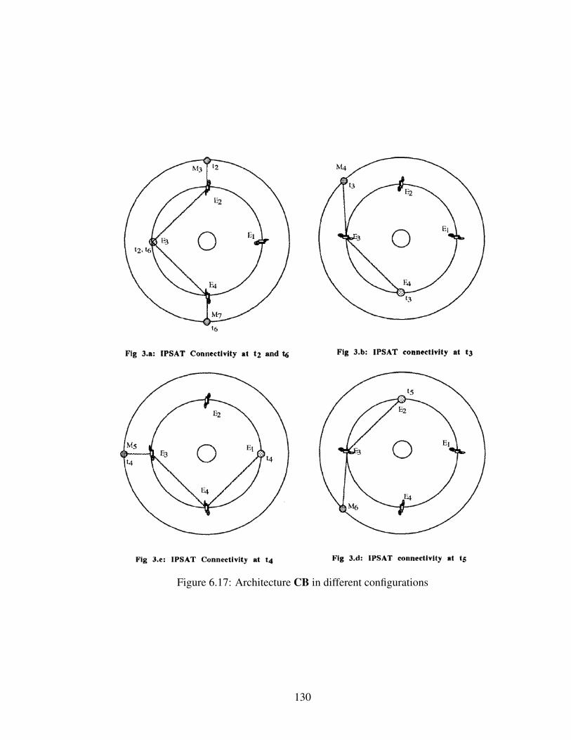
Figure 6.17: Architecture CB in different configurations
130

Figure 6.18: Implementation of the heliocentric concept CC based on FTL communica-tions in STK
cially designed for the use of the FTL communication technology that required transmitters
as close as possible to the midpoint between the two planets. Its implementation in STK is
presented on Figure 6.18.
6.4.3 Relays
The third type is composed by the relays that already have been detailed in the "Back-
ground" Chapter. A relay is an architecture of one satellite whose the main goal is to
ensure the link availability at all time. The architecture can be composed of a second satel-
lite that is added for the redundancy and/or to ensure a better coverage of the red planet.
Ten architectures of that type are considered in the survey. They are divided into four sub-
categories: the Lagrangian relays, the satellites on Mars orbit, the Gangale orbits and the
cyclers.
131

Lagrangian relays
The Lagrangian points have been introduced previously. In the following section, the con-
cepts using these points are depicted. In the survey, all the relays at Lagrangian points
are in the Sun-Mars system. In the mixed architectures (next sub-section), some concepts
include Lagrangian points in the Sun-Earth system.
The first and older design uses the stable points L4 and L5 points in the Mars-Sun sys-
tem. This concept has been introduced by James Strong in 1972 [95]. There are two options
for such a system: either it is used as an independent communication architecture, i.e. no
other satellite is required to ensure a continuous and reliable communication between the
Earth and Mars, or it is used with a constellation around Mars to overcome the solar con-
junction issue. In the first option EB, two satellites are placed respectively in L4 and L5,
as illustrated on Figure 6.19. The benefit of this solution is that, because those Lagrangian
point are stable, no maneuvers are required to keep the satellite on its orbit. It greatly
decreases the cost of the system and increases the lifetime. This solution has one main
drawback: as seen in Figure 6.19, it does not ensure a complete coverage of Mars. The
second option EC overcome this problem. The satellites at the Lagrangian points ensure
one hundred percent link availability while the constellation enable a complete coverage.
With a constellation around Mars, then only one satellite is required to overcome the solar
conjunction issue [41, 50].
The second concept introduced in 1992 uses the instable points L1 and L2 in the Mars-
Sun system. It is the architecture ED. This concept have been introduced by James Strong
in 1972 [95]. In such design, two communication satellites are placed in halo orbits around
the Lagrangian points L1 and L2, as shown on Figure 6.20. The two satellites are placed
180 degrees out of phase from each other in order to ensure a one hundred percent coverage
of Mars. The benefits of this architecture are that only two satellites are required to ensure
a complete coverage on the planet. The satellites are always in view of the Sun so they
take advantage of the Sun at all times to power the system, allowing more power available
132

Figure 6.19: Satellites configuration around the stable Sun-Mars Lagrangian points
for communication transmission. The orbit is selected to avoid Solar exclusion zone and
overcome the solar conjunction issue. This results in a 200,000 km out-of-plane amplitude
[51, 47].
Leading/trailing relays
The second sub-category of relay is the leading (trailing) satellite. This satellite is placed
on the Mars orbit but before (or after) Mars. Usually, the angle Satellite-Sun-Mars is about
20 degrees. The principle is the same as a halo orbit in L4 or L5. The benefit of this
solution over the halo orbit is that the satellite is closer. Less power is required to ensure
the communication between the satellite and Mars. Another point is that there is no risk of
collision with an asteroid in the vicinity of the Lagrangian points. The main drawback is
that the orbit is perturbed by the effect of the proximity with one of the Lagrangian points,
L4 for a leading satellite, and L5 for a trailing satellite. Thus, more propellant is required
to maintain the satellite on its orbit [50]. The concept with only one satellite leading Mars
by 20 degrees is the architecture EF, the concept with the leading and the trailing satellites
preceding/following Mars by 20 degrees is the architecture EG. Another option offered by
Breidenthal et al. is one single satellite leading Mars by 10 degrees [48] - architecture EJ.
133

Figure 6.20: Satellites configuration around the instable Sun-Mars Lagrangian points [96]
Gangale relays
The third sub-category of relay is a family of orbits called Gangale orbits, named after
its inventor. These orbits are characterized by the same orbital elements as the Martian
orbit except that the eccentricity is a bit smaller and the orbit plane is a few degrees out
of the Martian plane. That leads to a spacecraft that alternatively leads and trails Mars.
From Mars, the satellite seems to orbit Mars, but in reality, it orbits the Sun. From Figure
6.21, "MarsSat (A) rises North of Mars, (B) trails, (C) drops South of Mars and (D) leads
Mars" [97]. The original Gangale orbit has a Mars-Earth-satellite angle of 2.5 degrees
and a distance Mars-satellite of 22 million kilometers. A certain number of alternatives
exist with different eccentricities and different inclinations. There are various benefits to
these orbits. The spacecraft alternatively leads and trails Mars. Thus, the impact of the
Lagrangian points pulling the spacecraft from Mars, disappears. This reduces the amount
of propellant needed to maintain the satellite on its orbit and thus the cost. As long as the
inclination of the orbit is higher that the inclination of Mars’ orbit, transmissions can go
over the Sun and not just besides it. Furthermore, the distance Mars-satellite is the smallest
compared to other relay options. The drawback is that there is still a need for station-
134

Figure 6.21: Gangale orbit [97]
keeping and thus a propellant cost (higher than for Lagrangian relays) [97, 50]. In the
survey, the Gangale orbit derived is the one offered by Byford et al. as a good alternative
as a communication relay. The orbit as the same eccentricity as Mars and is inclined by
five degrees with respect to Mars [50]. The alternative with one satellite preceding Mars by
8 degrees is the architecture EH. The alternative with two satellites respectively preceding
and following Mars by 8 degress is the architecture EK.
Cycler
Another particular concept of relay in heliocentric orbit is the cycler. Its primary purpose
is not communication but rather the use of the cycler transportation vehicles as a commu-
nication relay during solar conjunctions. A cycler system is composed of one or several
spacecraft placed on a trajectory that periodically encounters two space elements, in this
context the Earth and Mars. This kind of transportation system could be an enabler to es-
tablish a settlement on Mars. Indeed, the vehicle is reusable for trips to and from Mars. It
is maintained on its orbit mainly thanks to gravity assist maneuvers at each planet encoun-
ters. At each planet encounter, a smaller vehicle called taxi would perform a hyperbolic
rendezvous with the cycler in order to transfer humans between the cycler vehicle and the
surface of the planet. Finally, it offers a large living and working environment for astro-
nauts flying to and from Mars, at reduced costs. The only study considering a cycler system
135

Figure 6.22: Earth-Mars S1L1 cycler trajectory
as a communication relay during solar conjunction was proposed by former astronaut Buzz
Aldrin and extensively investigated by a 51-student team at Purdue University in the con-
text of the Aldrin-Purdue project. A lot of cycler trajectories exist. In the Aldrin-Purdue
study the cycler considered is the S1L1 cycler first introduced by McConaghy in 2002
[98]. The S1L1 cycler is presented in Figure 6.22 over one period. It is a two synodic
period composed of two legs. The first leg, the inner leg, is short (S1). The eccentricity
is 0.2554 and the semimajor axis is 1.3039. It is followed by a long leg or outer leg, L1.
It crosses the Earth’s orbit and then Mars’ orbit 153 days later. The eccentricity is 0.1609
and the semimajor axis is 1.0483 AU. The interesting leg is the outer one, this is why two
spacecraft are placed on this orbit and launched at an interval of one synodic period [49].
This architecture is EI.
136

6.4.4 Mixed architectures
The last type of architectures is the mixed architectures. They are defined as a combina-
tion of architectures from at least two of the three previous categories. Generally, these
architectures fall into one of two categories:
• a combination of some satellites on heliocentric orbits with one or several relays at
Lagrangian points (such as architecture DB by Sands et al. [99] and DC by Kulkarni
et al. [100]) or
• a combination of a constellation around Mars with one or several relays at a La-
grangian points (such as architecture DD by Lorentz et al. [101], DE by Lida et al.
[102] or DH).
The problem with these architectures is that they are often not completely defined, such as
the SEI architectue by Hall et al.[103]. The number of satellites of the Martian constel-
lations are not defined. Sometimes, even the orbits are nor defined. This is why most of
the architectures in these category have not been implemented. To counteract this, a few
architectures have been created in this category as explained in the next Chapter.
6.5 Validation
HYPOTHESIS 2: If a framework in a modeling and simulation environment with the
required capabilities is designed then the communication architectures can be evaluated.
For this hypothesis, the validation criteria were the following:
1. Is the framework applicable to all the architectures?
2. Is the framework able to assess an architecture with respect to all the requirements?
3. Is the process repeatable?
137

The tool STK have been chosen for its capability. In terms of satellites, an impor-
tant number of satellites can be implemented. We have not reached any limit during the
implementation. The module Astrogator enable the computation and visualization of any
kind of orbits. All the architectures have been implemented. The framework defines the
environment and the way to implement the architectures. All the architectures have been
implemented in this framework following the same steps. The first criteria is satisfied.
Again, STK has been chosen for its capabilities. It is the only available tool that can
assess an Earth-Mars communication architectures generating some outputs on distances,
trajectories and communication budget at the same time. The framework enables the im-
plementation and the evaluation of all the architectures with respect to all the requirements.
The second criterion is satisfied.
The intent in the design of the framework was to build an environment in which all
the architectures can be implemented the same way based on the same assumptions. This
is what we did at that step. The way to implement the architectures and to evaluate them
with respect to each metrics have been extensively described in this Chapter and in the
Appendices. The process have been applied the same way to all the architectures. The
third criteria is satisfied.
138

CHAPTER 7
STEP 3 - RANKING THE ARCHITECTURES
The Chapter details the evaluation and the ranking of the architectures. As reviewed in the
Chapter "Methodology Formulation", section 4.4, this last step consists of implementing
the architectures described in the survey at Step 2, defining different weighting scenarios
applied to the set of requirements defined at Step 1, and ranking the architectures using a
TOPSIS. It concludes the methodology described in this thesis and leads to some results on
the "best" architecture for a set of selected requirements, associated with a chosen weight-
ing scenario on the requirements. In the following, I may refer to the architectures by using
the term "alternatives".
7.1 Evaluation of the architectures
7.1.1 Evaluation
Most of the architectures presented in the survey performed at Step 2 are implemented.
They are divided into four categories:
• the constellations around Mars (orange),
• the relays on heliocentric orbits (light blue),
• the mixed architectures that are combinations of relays and a constellation around
Mars (green), and
• the heliocentric constellations or networks of relays (dark blue).
Compare to the survey performed at Step 2, I chose to add six architectures to the list
of the implemented architectures. Each of these architectures is a combination of one re-
lay satellite and one Martian constellation. The reason for adding these architectures is
139

twofold. One the one hand, some relays are specially designed to be coupled with a con-
stellation, such as the relay EJ proposed by Breidenthal et al. [48] designed to overcome
the solar conjunction problem. On the other hand, from the âAIJBackgroundâAI Chapter it
is known that constellations perform well in terms of coverage but do not enable a contin-
uous link availability. On the contrary, relays ensure a full link availability, but a complete
coverage cannot be reached even with two relays. As a result, to have a full link availability
and a complete coverage at the same time, a mixed architecture is needed. There is only
one mixed architecture implemented from the survey. This is why these architectures have
been added. However, the intent of this thesis is not to perform some kind of optimization
or to offer new propositions of design.
To create the architectures, I picked three relays of interest.
1. The relay EJ by Breidenthal et al. [48], that is designed to overcome the solar con-
junction problem.
2. One satellite on Gangale orbit EK [97], as Byford et al. have concluded that the Gan-
gale orbit is the best location to place a relay satellite to overcome solar conjunction
issues while minimizing the power required [50].
3. A relay at the Lagrangian point Sun-Mars L4 EC because this location is one of the
most-used location for Earth-Mars communication relays.
With these three relays, a constellation has to be added. We chose to add two constellations.
1. The Draim constellation AB as it is the best design in terms of coverage (full cover-
age) with the minimum number of satellites [104].
2. The areosynchronous constellation AO composed by three satellites, as it is the de-
sign the most cited in mixed architectures that are not completely defined [84].
The code of these architectures starts with the letter "F". They are described in Table 7.1.
140

Table 7.1: Mixed architectures added for the implementation
Code Relay ConstellationFB Breidenthal relay EJ Draim constellation ABFC Breidenthal relay EJ Three-satellites areosynchronous AOFD Gangale orbit EK Draim constellation ABFE Gangale orbit EK Three-satellites areosynchronous AOFF Sun-Mars Lagrangian point L4 EC Draim constellation ABFG Sun-Mars Lagrangian point L4 EC Three-satellites areosynchronous AO
In the âAIJProblem DefinitionâAI Chapter, the technique selected to rank the alterna-
tives is the TOPSIS. To be able to perform the TOPSIS, a table linking the alternatives to
the metrics in a quantitative way is required. STK is used to fill this Table. The result is
given Table 7.2.
Compared to the list of architectures presented in Appendix C, three groups of archi-
tectures have not been implemented. The first group is composed of the architectures that
are not completely defined. They are usually mixed architectures. Indeed, some architec-
tures such as architecture DH has "some satellites in low Mars orbit". I have no additional
information on the number or the orbit of those satellites. Such an architecture is no imple-
mented in order not to make any assumption on this architecture. The last two groups are
the architectures with one or several satellites in orbit around the Lagrangian points L1 and
L2 and the cycler architecture EI. This is because the implementation of these two groups
of architectures is more complicated as the requirement for propulsive maneuvers cannot
be omitted. They will be implemented in future work, they have not been implemented yet
by lack of time.
7.1.2 Results by criterion
Before ranking the architectures using some weighting scenarios and the TOPSIS, they
are ranked with respect to each requirement one by one. The goal is to see if the trends
underlined in the âAIJBackgroundâAI Chapter are found with the present methodology.
The results are given on Table 7.3.
141

Table 7.2: Results of the implementation and evaluation of the architectures
Code Access Meancoverage Delay Number of
satellites Energy
AB 97.36% 99.14% 3.815E+08 4 1.455E+17AC 97.36% 98.29% 3.815E+08 4 1.455E+17AD 97.38% 33.86% 3.815E+08 6 1.455E+17AE 97.38% 52.58% 3.815E+08 6 1.455E+17CC 100.00% 78.73% 5.278E+08 12 1.558E+16AF 97.38% 33.62% 3.815E+08 6 1.455E+17AG 97.38% 31.15% 3.815E+08 6 1.455E+17AH 97.41% 31.45% 3.815E+08 5 1.455E+17AI 97.39% 46.97% 3.815E+08 6 1.455E+17CB 100.00% 67.89% 6.080E+08 3 4.499E+16AJ 97.41% 45.30% 3.815E+08 6 1.455E+17AK 97.38% 45.31% 3.815E+08 6 1.455E+17AL 97.40% 43.79% 3.815E+08 6 1.455E+17AM 97.38% 100.00% 3.815E+08 6 1.455E+17AO 97.36% 97.71% 3.815E+08 3 1.455E+17BB 97.39% 100.00% 3.815E+08 20 1.455E+17BC 97.40% 100.00% 3.815E+08 15 1.455E+17DE 100.00% 97.68% 5.321E+08 7 2.387E+16EC 100.00% 50.00% 6.119E+08 1 5.973E+16EB 100.00% 82.28% 6.432E+08 2 7.851E+16EF 100.00% 50.00% 5.881E+08 1 1.325E+17EG 100.00% 94.20% 5.881E+08 2 1.544E+17EH 100.00% 88.60% 4.223E+08 2 1.501E+17EJ 100.00% 49.99% 4.303E+08 1 1.510E+17EK 100.00% 50.00% 4.112E+08 1 1.403E+17FB 100.00% 99.14% 4.303E+08 5 1.510E+17FC 100.00% 97.71% 4.303E+08 4 1.510E+17FF 100.00% 99.14% 6.119E+08 5 5.973E+16FG 100.00% 97.70% 6.119E+08 4 5.973E+16FD 100.00% 99.14% 4.112E+08 5 1.403E+17FE 100.00% 97.71% 4.112E+08 4 1.403E+17
142

Table 7.3: Ranking of the architectures by requirement
143

Link availability
Regarding the link availability, the architectures can be classified into two categories. One
is composed by the Martian constellations that have a link availability around 97%. The
second is composed by all the other architectures that all have a link availability of 100%.
The constellations around Mars are the only architectures not to overcome the problem
caused by solar conjunction events.
Mean coverage
In terms of coverage, the top-first architectures are the two navigation constellations, the
MarsWeb constellation and the Draim constellation as well as the mixed architectures using
the Draim constellation. They have a mean coverage above 99%. Second, between 80%
and 99%, there are the mixed architectures, some constellations, and the relay architectures
with two relays. After that, there are the heliocentric constellations, the relay architectures
with only one relay. Then, the other constellations come. What is interesting is that the
main asset of a constellation is to provide a full coverage of the planet. Yet, half of the con-
stellations perform less well than only one relay. Those constellations generally perform
less well in the other criteria too, they are a non-sense regarding the requirements selected.
Propagation delay
For the propagation delay, all the constellations around Mars have the same performance
and come before all the other alternatives. After them, the alternatives that have the best
performance in the remaining ones are those for which the relay is the closest to Mars. The
architectures with a relay at a Lagrangian point L4 or L5 in the Sun-Mars system are the
worst for the propagation delay.
144

Energy
In terms of energy, the trend is likely the opposite to the propagation delay. The best
architectures are those for which the satellites are well-distributed in the deep-space. There
are those with several satellites in heliocentric orbit, far from Mars. Then, there are the
constellations, having all the same results. Finally, the architectures with a relay close to
Mars are the worst.
Number of satellites
Concerning the number of elements, the best architectures are the relays, as they need only
one or two satellites. The, the mixed architectures and the constellations come. The worst
alternatives are the navigation constellations as they require each point of the surface to
be covered by at least three satellites at the same time. They provide an additional service
(navigation) that is not accounted in our requirements.
7.2 Weighting scenarios
Figure 7.1: Weighting scenarios
145

Table 7.4: Weighting scenarios
Scenario: #1 #2 #3 #4Link availability 1/5 1/2 0 0Mean coverage 1/5 1/2 0 0Propagation delay 1/5 0 0 1/2Energy 1/5 0 1/2 1/2Number of satellites 1/5 0 1/2 0
The architectures have been evaluated. Before performing the TOPSIS, several weight-
ing scenarios have to be defined. Indeed, in the TOPSIS, the importance given to each
requirement can be different from one requirement to another. This was one of the reasons
why this technique has been selected. Four scenarios have been established. They are de-
fined in the Table 7.4 and represented on Figure 7.1. The choice of these four scenarios is
explained in the following. Other scenarios are relevant but the objective of the thesis is
to demonstrate a methodology and not to extensively compare the different architectures.
Once the TOPSIS is implemented in an Excel file, the scenarios can be changed at will.
Scenario 1
The requirements in this work have been carefully selected and justified. They represent
the essence of the problem of designing an Earth-Mars communication architecture. Thus,
it is relevant to see what is the "best" architecture, giving the same weight to all the require-
ments. This is the scenario 1.
Scenario 2
The initial goal is to provide a permanent communication architecture between Earth and
Mars, for all kind of missions, including manned missions. As the architecture has to
served any mission, the surface covered is the first requirement. As manned mission are
included, a permanent link is needed between Earth and Mars. Thus, the link availability
and the coverage can be considered as the two main requirements. This is way, the second
scenario focuses only on those two.
146

Scenario 3
As explained at Step 1, the number of elements has been added to counterbalance the data
rate (translated into energy as explained at Step 2). Indeed, adding elements potentially re-
duces the distance between the elements and thus the power requirement. However, having
more elements increases the cost of the overall architecture while decreasing the feasibil-
ity. Thus, the third scenario illustrates the trade between the energy and the number of
satellites.
Scenario 4
In the previous section, when ranking the architectures for each requirement one by one, an
opposite trend has been noticed between the propagation delay and the energy. Reducing
the distance between elements often implies the increase of the end-to-end distance for the
signal. This trade-off between the propagation delay and the energy is the purpose of the
last scenario.
7.3 Ranking the alternatives
The evaluation matrix is given Table 7.2 and the scenario Table 7.4. The formulas used
to perform the TOPSIS and described in the "Problem Definition" are implemented in an
Excel sheet and applied to the evaluation matrix. The results architectures are ranked from
the best to the worst for each scenario on Table 7.5. For each scenario, the results are
discussed in the following and presented, by category, on a graph plotting the distance
from the Ideal Negative point against the distance from the Ideal Positive point for each
architecture. The full set of values for Si∗, Si− and C for each alternative for each scenario
is given in Appendix.
147

Table 7.5: Ranking of all the alternatives by scenario
148

7.3.1 Scenario 1
As a reminder, the scenario gives the same weight to all the requirements. The best alterna-
tive for this scenario is the architecture CB, an architecture with three relays in heliocentric
orbit, on the same orbit as the Earth. Indeed, this solution is a good compromise between
all the requirements. In particular it performs very well on three requirements: it has only
three satellites, the link availability is at 100% and the distance between satellite is mini-
mized because the relays are placed on the Earth orbit, which is better than on the Mars
orbit. The coverage is at 68% which is average. The architecture do not perform well on
propagation delay but this the only requirement on which the result is bad. The second best
alternatives are those with a relay at the Lagrangian points L4 and/or L5 in the Sun-Mars
system.
Looking at Figure 7.2 where all the architectures are plotted, it can be seen that relays
perform better than mixed architectures that perform better than constellations architec-
tures, on average. Among the relays, the architectures with two relays perform better than
the architecture with only one relay. In terms of performance, it costs less to add a satellite
and increase the coverage by 40% than not adding the satellite. On the contrary, relays per-
formed better than a mixed architecture with the same relay and a constellation. In terms
of performance, it costs more to add three or four satellites than increasing the coverage by
10%. There is a trade between the coverage and the number of elements underlying in this
scenario.
The three best constellations are the three-satellites areosynchronous constellation AO,
then the Draim constellation and AB then the four-satellite areosynchronous constellation
AC. This ranking illustrates again the trade-off between the number of elements and the
coverage.
Finally, the worst alternatives are those with a lot of satellites, in particular the nav-
igation constellations BB and BC. As already underlined in the previous section, these
constellations provide an additional service that is not taken into account in our set of re-
149

Figure 7.2: Results from Scenario 1 (Equally weighted scenario)
quirements.
7.3.2 Scenario 2
The scenario 2 only take into account the link availability and the mean coverage, with the
same weight for the two requirements. It shows how the architectures perform for the two
main requirements. As visualizes on Figure 7.3, the architectures are aligned on the plot.
Moreover, the architectures are ranked by category in this scenario.
The best architectures for this scenario are the ones with a full link availability and a full
coverage, that is to say the mixed architectures with one relay and a Draim constellation
FB, FD and FF. After them, the architectures that perform well with a value of C above
0.95 are the constellation ensuring a full coverage, then the mixed architectures with a
three-satellite areosynchronous constellation, finally the areosynchronous constellations.
After that, the classes are ranking in the order from the best to the worst: the two-
relay alternatives, the heliocentric constellations, the Martian constellation AE that have a
coverage right above 50%, the one-relay alternatives and finally the architectures with less
150

Figure 7.3: Results from Scenario 2 (Link availability and coverage)
than 50% of mean coverage. These last correspond to the constellations already emphasized
at the beginning of the Chapter while ranking the architectures in by mean coverage.
7.3.3 Scenario 3
The scenario illustrates the trade-off between the energy, that is to say the distance between
the elements and the number of elements. The general idea is that the more satellites
they are, the closer they should be. However, as the distance considered is the largest
distance between two elements, the Martian constellations are expected to be badly ranked
in this scenario. Indeed, the best alternatives are those with a few number of satellites well-
distributed in the deep-space. The first architecture is the relay at the Lagrangian points L4
in the Sun-Mars system EC. It has only one satellite and the distance with Earth is smaller
than the one for relays that are closer to Mars. The second architecture is the architecture
CB of heliocentric relays, the same that came first in the scenario 1. The assets of this
architecture is that there are only three satellites well-distributed in the deep-space. The
third architecture is the combination of the two relays at the Lagrangian points L4 and/or
151

L5 in the Sun-Mars system EB.
Figure 7.4: Results from Scenario 3 (Trade-off energy vs number of satellites)
All the architectures are distributed on the plot on Figure 7.4. In the first third of
the ranking come the mixed architectures with a relay at the Lagrangian points L4 in the
Sun-Mars system and then all the relays. After that, there is an alternation between con-
stellations with five or less satellites and mixed architectures. The ranking ends with con-
stellations of more than five satellites. Again, the very last architectures are the heliocentric
constellation of twelve satellites CC and the two navigation constellations around Mars BB
and BC, as in the scenario 1.
Among the relays, the relays with only one satellites perform better than the relays with
two satellites, as expected. What is interesting is that the relays that are further than Mars
perform better than the relays closer to Mars. There is the idea that an architecture where
the satellites are well-distributed performs better. This result goes against the conclusions
drawn be Byford et al. [50]. In the paper, they review the optimal location of a relay
satellite in terms of location and power requirements. This is because they assume that we
can have larger antennas on Earth that will be able to transmit more power. Their reasoning
152

is to say that they want to minimize the distance from Mars to minimize the power of the
antenna on-board of the relay. This trade is explained in the "Background" Chapter. This
difference in reasoning explains the difference in the results. We want to minimize the
overall power required whereas they are looking for minimizing the power requirement of
one element only.
7.3.4 Scenario 4
This last scenario discusses the trade-off between the energy, the maximum square of the
distance between two elements and the propagation delay, the maximum end-to-end dis-
tance. This trades comes from the idea that reducing the distance between elements implies
to add some elements and increase the distance travelled by the signal. On Figure 7.5 where
the results are plotted for this scenario, it can be seen that there is a gap between the five
first alternatives, that are themselves spaced from one to another, and the other alternatives.
Figure 7.5: Results from Scenario 4 (Trade-off in terms of distances)
In this scenario, the architectures that perform well are those with satellites on Earth or-
153

bit. Placing satellites on Earth orbit reduces the maximum distance between two elements.
Compared to a satellite on Mars orbit, for a two satellites separated by the same angle, the
distance between the two will be smaller on Earth orbit as the radius of Mars orbit is bigger
than the one of Earth orbit. At the same time, it does not increase to much the end-to-end
distance. The first architecture is CC, the heliocentric constellations of twelve satellites
on an 1.5 au radius orbit. Then comes the mixed architecture DB with two satellites at
the Lagrangian points L4 and L5 in the Sun-Earth system. The third position is for the
architecture CB. From those results, the reader should be surprise that there are no more
proposition of design with satellites on Earth orbit, especially at the Lagrangian points L4
and L5.
The fourth to seventh ranks are occupied by architecture with relays at the Lagrangian
points L4 and/or L5 in the Sun-Mars system. After that, there are all the constellation that
have the same performance for this scenario as the difference of altitudes of the satellites
in the constellation is negligible with respect to the distance Earth-Mars.
At the end of the ranking, there are the other option with a relay. Among these option,
those that have the best results are those with a relay close to Mars. Indeed, the distance
Earth-relay is important but being close to Mars decreases the end-to-end distance.
7.3.5 Comparison of the results from the different scenarios
When looking at Figure 7.5, the architecture CB, illustrated on Figure 7.6, is in the top-
three ranking of all the scenarios except the second one. This may be surprising as the
concept is original compared to classical relays and Martian constellation. There are two
possible conclusions to this result. Either we did not consider enough requirement to have
an accurate overview of the problem, ignoring the station-keeping problem for example.
Either designers stay classical and offer solutions that looks like those that are well-known:
the Lagrangian points and the constellations. This last hypothesis is close to what Sanctis
writes about the design of constellations. He said that it is impossible to explore all the
154

design space for a deep-space architecture. He also underlined that the design of constella-
tions is far behind because of its complexity, the authors restraining themselves to circular
orbits [41]. This result underlines the incompleteness of the comparisons, this design being
never considered in the comparative studies found in the literature, and the lack of design
space exploration. It also calls for implementing architectures such as the cyclers, that
could be a good alternative.
Figure 7.6: Architecture CB
Besides this particular design, the alternatives also performing well are those with re-
lays at the Lagrangian points L4 and/or L5 in the Sun-Mars system, FF, EC, EB and FG.
They have good performance in all the scenarios. Relays at Lagrangian points L4 and L5
are classical concepts often involved in the design of a permanent interplanetary architec-
ture. It can be explained by the good coverage provided with only two relays and the full
availability ensured.
On the other end, looking at alternatives with poor performance, there are the navigation
constellations BB and BC as already discussed. It is because they provide the navigation
service that is not taken into account in the set of requirements selected and that implies
a higher number of satellites. There is also the architecture CC that only excel in the last
155

scenario, taking the first place. This architecture is designed to enable the use of a specific
communication technology, the FTL communications. These observations highlight the
importance of the selection of the requirements. The requirements drive the selection of
the best solution.
Finally, the constellations AD, AE, AF, AG, AI, AJ, AK, and AL have bad results in all
the scenarios. The four first are compared by Bell et al. [42]. They conclude that 4retro111
(architecture AF) is the best of them. The difference with our analyze is that they make
a trade on the altitude of the satellites. A lower altitude constellation have a higher data
return and a greater precision but it has a higher gap time. This trade is not taken into here
as it is too precise and too constellation-related. Our comparison is at a higher level. The
four later have been designed and compared by Sanctis et al. to cover specific areas of the
Martian surface [44]. Again, it cannot be compared with our study as our goal is to cover
all the surface of the planet. Again, these constellations are not designed to correspond to
the set of requirements selected in this thesis. It also underlines the lack of design space
exploration that is mainly focused on Martian constellations. Indeed, they represent almost
half of the architectures gathered from the literature.
7.4 Validation
HYPOTHESIS 3: If a Technique for Order Preference by Similarity to Ideal Solution
is implemented then the comparisons performed on the communication architectures for
different weighting scenarios are relevant.
For this hypothesis, the validation criteria were the following:
1. Are all the alternatives ranked?
2. Does the resulting ranking follow the trends expected from the literature?
3. Does the resulting ranking vary from one weighting scenario to another, in a cogent
way?
156

In the work presented above, all the alternatives have been ranked in all the scenario.
The first criterion is satisfied. The TOPSIS is an adequate technique to rank our alternative.
At the step we designed different weighting scenarios to illustrate some interesting
trade-offs in our problem. All the results obtained have been discussed and explained by
reasoning. The differences with the literature have been justified. They are explained by
a difference on the assumptions made at the beginning or a difference in the level of mod-
elization of our problem. Indeed, this study is a high-level study with the main advantage
of being able to compare all the possible concepts and not only a relay of a constellation.
The second criterion is validated.
Finally, the different weighting scenarios give totally different results. The difference
have been explained and the results compared. The third criterion is validated.
157

CHAPTER 8
CONCLUSION
8.1 Summary
Because of the human imperative for exploration, it is very likely that a manned mission
to Mars occurs by the end of the century. Mars is one of the two closest planets to the
Earth, it is very similar to the Earth and it could be suitable to host a manned settlement.
Sending humans to Mars is a technological challenge above all. Among the technologies
needed, some of the most important relate to communications. Women and men on Mars
need to be able to receive support from the Earth, communicate with other human beings
on Earth and to send back the data collected. A reliable and continuous communication
link has to be provided between the Earth and Mars to ensure a safe journey to Mars. How-
ever, the communication between the Earth and Mars is challenging because of the distance
between the two planets and because of the obstruction by the Sun that occurs for about
twenty-one days every 780 days. Because of the cost of communication systems and the
number of exploration missions to Mars, it has been established that a permanent commu-
nication architecture between the Earth and Mars is the most profitable option. From these
observations, the research goal established for this thesis is to enable reliable and con-
tinuous communications between the Earth and Mars through the design of a permanent
communication architecture.
A literature review of the communication architectures between the Earth and Mars
revealed that a lot of concepts have been offered by different authors over the last thirty
years. However, when investigating ways to compare the variety of existing architectures,
it becomes very apparent that there were no robust, traceable and rigorous approach to do
so. The comparisons made in the literature were incomplete. The requirements driving
158

the design the architectures were not defined or quantified. The assumptions on which the
comparisons are based were different from one architecture to another and from one study
to another. As a result, all the comparisons offered were inconsistent. This thesis addresses
those gaps by developing a methodology that enables relevant and consistent comparisons
of Earth-Mars communication architectures and supports gap analysis. This methodology
is composed of three steps that correspond to the three main part of the thesis:
1. the definition and the mapping of the requirements against the communication sys-
tem,
2. the evaluation of the architectures, and
3. the ranking of the architectures.
For each of these steps a research question was asked, and a hypothesis was formulated.
All the hypotheses have been validated along the study. Here, is a summary of each step.
The first step of the methodology consists in organizing the requirements to emphasize
their interactions with the different parts of the communication system (the architecture,
the hardware and the software). The research question corresponding to this step was:
"What process enables the mapping between the requirements and the communication sys-
tem?". To address this question the hypothesis 1 was: "If a relationship matrix is developed,
then the requirements are mapped appropriately against the communication system". Thus,
a relationship matrix has been proposed. Beforehand, it was necessary to define a set of
requirements, as a basis to assess the architectures and develop the methodology. As the re-
quirements are often poorly defined, a review of papers about communication requirements
for a manned mission to Mars has been performed. Then, a limited set of requirements has
been selected to grab the essence of the problem while staying as simple and transparent as
possible. Finally, the mapping took place. The hypothesis 1 was validated.
The second step of the methodology consists in evaluating the architectures. Indeed,
an evaluation matrix is required to be able to rank the alternatives. The research ques-
159

tion corresponding to this step was: "How to assess the communication architectures so
that they can be consistently and rigorously compared?". To address this question the hy-
pothesis 2 was: "If a framework is designed in a physics-based modeling and simulation
environment with the required capabilities then the communication architectures can be
evaluated". A modeling and simulation environment is needed. The capabilities required
are the computation of trajectories for interplanetary missions, the computation of the cov-
erage of the martian surface, the computation of the access between two elements and the
computation of distances, the possibility to implement communication technologies and
protocols as well as the generation of link budgets. The choice was made toward an avail-
able and user-friendly tool offering all the capabilities needed for the demonstration of the
methodology and its extension: STK (Systems Tool Kit). A framework has been designed
in this environment to provide a unique approach to enable the evaluation of all the archi-
tectures based on the same assumptions. It is the basis to ensure a consistent and repeatable
methodology, filling one of the gaps addressed by our methodology, the inconsistencies on
the assumptions made on technologies’ capability (gap 2). The metrics associated with the
requirements selected have been defined. A survey of the existing Earth-Mars communica-
tion architectures has been performed to populate the list of alternatives. These alternatives
have been implemented in STK, following the framework designed. The hypothesis 2 was
validated.
The third step of the methodology consists in ranking the alternatives. The research
question corresponding to this step was: "How can communication architectures be consis-
tently ranked?". First the architectures are evaluated to fill the evaluation matrix. To rank
the alternatives, a methodology enabling a quantitative ranking of a discrete set of alterna-
tives has been selected. This is the hypothesis 3: "If a Technique for Order Preference by
Similarity to Ideal Solution (TOPSIS) is implemented then the comparisons performed on
the communication architectures for different weighting scenarios are relevant". To demon-
strate the process, four weighting scenarios for the requirements have been carefully chosen
160

to illustrate some trade-offs for such a system. The first scenario put the same weight on
all the requirements. The second scenario focuses on the two main requirements that are
the coverage and the link availability. The third scenario illustrates the trade between the
energy (representing communication performance) and the number of elements. The last
scenario illustrates the a trade in terms of distances, between the propagation delay and the
energy. The architectures were first ranked requirement by requirement. Then, the TOPSIS
was applied to the evaluation matrix for the different weighting scenarios. The results were
commented. Overall, one of the best architectures for all the scenarios for the set of chosen
requirements is the heliocentric concept CB with three satellites on Earth orbit. This result
illustrates one of the gap filled by our methodology, the incompleteness of the comparisons
(gap 3). Indeed, this architecture was never considered in the comparison studies found in
the literature. It shows the incompleteness of the previous comparisons and emphasizes the
lack of design space exploration for Earth-Mars communication architectures. The worst
architectures are the navigation architectures and some martian constellations. In the first
case it is because a service not taken into account in the requirements is provided. In the
second case, it is because these constellations are designed to cover some selected areas of
the surface of Mars, and not to provide a complete coverage as it is the intent in this thesis.
This result underlines the necessity of well-defining the requirements when designing and
comparing architectures, as the requirements drive the design and impact the ranking of the
architecture. This finding makes the link with one of the gaps filled by our methodology,
the lack of definition of the requirements (gap 1). All the architectures have been ranked
for different weighting scenarios and the rankings follow expected trends. The hypothesis
3 was validated. The methodology is demonstrated.
To conclude, this thesis offers a transparent and repeatable methodology filling several
gaps in the comparison of Earth-Mars communication architectures:
1. the lack of definition of the requirements,
2. the lack of a unique approach to implement and assess the architectures based on the
161

same assumptions, and
3. the lack of a process to rigorously compare all the architectures.
The methodology provided is demonstrated on a restricted scope, it aims at being extended
as developed in the Section "Future work". It has various capabilities including:
• ranking Earth-Mars architectures based on a chosen set of requirements,
• performing gap analysis and sensitivities analysis on communication technologies
and protocols, and
• performing design space exploration on architectures, not restricted to Earth-Mars
architectures but also but interplanetary architectures in general, not restricted to
communication architectures.
8.2 Contributions
Four contributions were made in this thesis. They are related to the methodological gaps
identified in the "Background" Chapter and/or result from the shortcomings identified from
the literature.
8.2.1 The methodology
Before the present research, there was no robust, consistent and rigorous means to rank and
quantitatively compare the architectures. As underlined while performing the review of the
requirements on Earth-Mars communication architectures, the process "Establish the need
→ Define the requirements → Associate some metrics → Evaluate the architectures →
Rank the architectures" has never been followed consistently for Earth-Mars communica-
tion architectures. The comparisons made in the past are always incomplete or inconsistent
because the requirements are not defined, the assumptions are not the same for all the archi-
tectures or the comparison is performed among a small amount of architectures. The main
162

contribution of this thesis is the answer to the research objective: Develop a methodology
that enables relevant and consistent comparisons of Earth-Mars communication architec-
tures and supports gap analysis. The methodology not only ranks but also quantitatively
compares the architectures, that is to say it can quantifies the differences between archi-
tectures for an infinite number of scenarios. This thesis offers a repeatable, traceable,
transparent and rigorous methodology to carry out the process from the beginning to the
end, cogently.
8.2.2 The framework in STK
The second contribution deriving from the methodological gaps highlighted in the "Back-
ground" Chapter is the design of a framework that enables the evaluation of all the archi-
tectures according to similar assumptions. The consistent and quantitative framework is a
key element of the methodology developed as part of this work.
8.2.3 The requirements review
Another methodological gap is the lack of definition of the requirements. The first idea
has been to look at all the papers about Earth-Mars communication architectures to see the
kind of requirements and metrics that are used to design the architectures and to compared
them. From this work, some conclusions have been drawn. The most cited requirements
have been identified. However, the definition of those requirements was almost always
incomplete. This is why a review of papers focused only on the requirements on Earth-Mars
communication architectures have been done. The study of the requirements on Earth-
Mars communication architectures for manned missions associated with some metrics and
impacts on the design of the architectures have never been proposed before. The review
has been initiated in the thesis and will be completed in future work with the impacts of the
requirements on the final design of the architecture.
163

8.2.4 The architectures survey
The last contribution of this thesis is the survey of the Earth-Mars communication archi-
tectures at step 2. No existing paper offers an exhaustive survey of the multiple concepts
proposed by different authors for this type of architectures.
8.3 Future work
The intent of this thesis was to enable reliable and continuous communications between
the Earth and Mars through the design of a permanent communication architecture. The
means to meet this goal was the methodology previously developed. This methodology
was demonstrated on a limited scope. Indeed, only the architectures and the interactions
with the hardware were considered. When assumptions on the technology were needed, the
frequency considered were the X-band. This work focuses only on existing technologies
and architectures. Impacting the requirements, this work is limited to the conceptual design
phase and only the operation phase of the cycle of the system is considered. Consequently,
this thesis can be extended in many ways, as discussed below.
8.3.1 Implementing the communication technology and performing a sensitivity analysis
The first track is to extend the methodology to take into account not only the architecture
but also the technology. Indeed, one of the methodological gap is that the assumptions on
the technology capabilities are inconsistent from one study to another. Implementing the
technologies are easy and quite straightforward in STK but it pushes the implementation
of the architecture to a lower level. Antennas, receivers and transmitters have to be defined
for each elements of the architecture. A first step would be to choose an architecture, to
implement two different technologies such as an X-band and a optical communication and
to assess the impact of the technology on the architecture. When doing so, one must be
careful not to compare two architectures with two different communication technologies.
164

Indeed, in such case, conclusions could not be drawn as it would be impossible to assess
whether or not the difference originates from the technology or the architecture.
Another avenue for future work consist in implementing one technology and changing
the capability of the technology. For example, a Ka-band is chosen and the solar exclusion
angle is modified. This study is a sensitivity analysis. It correspond to the last step of the
process presented in the "Methodology Formulation" Chapter. The results of such a study
would enable the assessment of the impact of each technology capability on the metrics
of interest. By quantifying the impact, the manufacturer and the designer would be aware
of the impact of one technological development compared to one another. Eventually they
would be able to identify what improvements would be needed given the requirements they
set on the system and the performance desired for the system .
The last step to have a complete modeling of the communication system is to implement
the protocols. This option is also possible in STK.
8.3.2 Implementing new architectures and performing optimization studies
Another avenue for future work consists in remaining at the level of the architectures but
to implement more architectures. Indeed, some architectures of the survey have not been
evaluated. This is either by lack of time for the halo orbits at Lagrangian points L1 and
L2 and for the cyclers or by a lack of definition of the architecture. In the first case, the
halo orbits have not been implemented because they require the implementation of the
maneuvers for station-keeping in order to stay on the halo orbit for the whole duration
of the synodic period. This is required to have an accurate evaluation of the coverage.
Performing a deep study of cycler vehicles could be interested given that the best overall
concept is a heliocentric concept, just as the cycler. It could extend the design space to new
types of trajectories and offer interesting results.
Some architectures have not been implemented because the concept was not totally de-
fined. Indeed the purpose of this thesis was limited to the comparison of existing concepts.
165

No optimization or modification of a design was performed. Now that the framework has
been demonstrated and that the methodology is validated, another extension of this thesis
could be to optimize one architecture for a selected set of requirements. STK enables de-
sign space exploration and trade studies thanks to the STK Pro and the Analyzer modules.
It could be a good way to use the framework to offer new architectures designed for an
established set of requirements and to perform exploration of the parts of the design space
that is usually left apart, such as the heliocentric concepts and the relays on the Earth orbit.
8.3.3 Extending the set of requirements and testing other weighting scenarios
A final avenue for future work consists in modifying the set of requirements and the metrics.
First, a metric corresponding to the concept that the entire surface of the Red planet is
covered at all times should be introduced. By only computing the mean surface covered
over one day, one does not properly assess the architecture with respect to the need of
having a complete and continuous communication link between the two planets. With the
link availability requirement, the continuity of the link between the Earth surface and the
sphere of influence of Mars can be assess, but not with a specific location on the Mars
surface. With the coverage requirement the fact that each point is reached during the day is
assessed. On the contrary, the fact that any point should be reachable at any time is never
assessed. To evaluate this idea, an additional metric such as the "full coverage area" could
be added. This metric would compute the percentage of the surface covered at all times
over one synodic period.
From the literature review, the requirements have been identified, including a quite
exhaustive list made by Bhasin and Hayden [76]. Other requirements could be chosen,
including other phases of the mission or other sub-systems of the satellites. Thereby, a
requirement on station-keeping or on the cost to settle the architecture could be taken into
account. A trade mass/size /power could also be completed, STK has the capability to assist
this trade.
166

Other requirements could be chosen to better address some work identified in the liter-
ature. Two studies in particular could be of interest. The first one concerns the evaluation
of the requirement on the coverage of polar and equatorial regions, as done by Bell [42].
The second one concerns the minimization of the distance between the relay and Mars,
as proposed by Byford [50]. These two studies would be particularly interesting with the
implementation of the technology.
Finally, a reflection on the way to implement and evaluate the non-functional require-
ments would be interesting. A requirement such as the reliability fr example, could be one
of the main requirement in a manned mission. Another requirement that is very important
for every space mission is the cost. The cost is difficult to implement. An easy way to take
it into account is to assume that every satellite has the same cost. With this assumption, the
cost is equivalent to the number of satellites. This is the requirement taken into account in
this thesis. To add some accuracy to the modelling of the cost, the station-keeping require-
ment can be implemented. The more fuel is required, the more expensive the satellite is.
The limitation is that it is still assumed that all the satellites have the same cost. However,
this assumption is completely wrong. The cost of a launching a nanosatellite can be about
$200 000 whereas launching an heavy satellite can reach a cost of $400 millions, and this
is only for the launch. A complete model has to be developed. Other considerations, such
as the technology used have to be taken into account as the choice of the technology, has to
be added to the model. Indeed, it has an influence on the mass and the heavier a satellite is,
the more expensive it is. An accurate model of cost is complicated and requires a certain
number of assumptions.
167

Appendices
168

APPENDIX A
ARCHITECTURES AND THEIR REQUIREMENTS
169

Table A.1: List of the architectures with the associated requirements
170

Table A.2: List of the architectures with the associated requirements (continued)
171

Table A.3: List of the architectures with the associated requirements (continued)
172

Table A.4: List of the architectures with the associated requirements (continued)
173

Table A.5: List of the architectures with the associated requirements (continued)
174

APPENDIX B
REQUIREMENTS REVIEW
175

Table B.1: Requirements review
176

Table B.2: Requirements review (continued)
177

Table B.3: Requirements review (continued)
178

Table B.4: Requirements review (continued)
179

APPENDIX C
ARCHITECTURES SURVEY
180

Table C.1: Architectures survey
181

Table C.2: Architectures survey (continued)
182

Table C.3: Architectures survey (continued)
183

Table C.4: Architectures survey (continued)
184

Table C.5: Architectures survey (continued)
185

APPENDIX D
RESULTS BY SCENARIO
186

Table D.1: Ranking of the architectures using the TOPSIS for the scenario 1
187

Table D.2: Ranking of the architectures using the TOPSIS for the scenario 2
188

Table D.3: Ranking of the architectures using the TOPSIS for the scenario 3
189

Table D.4: Ranking of the architectures using the TOPSIS for the scenario 4
190

REFERENCES
[1] E. Musk, Making Life Multiplanetary, Adelaide, Australia, 2017.
[2] Mars One.
[3] B. L. Ehlmann, J. Chowdhury, T. C. Marzullo, R. Eric Collins, J. Litzenberger,S. Ibsen, W. R. Krauser, B. DeKock, M. Hannon, J. Kinnevan, R. Shepard, andF. Douglas Grant, “Humans to Mars: A feasibility and cost-benefit analysis,” ActaAstronautica, Living in Space: Scientific, Medical and Cultural Implications. A Se-lection of Papers presented at the 14th IAA Humans in Space Symposium, vol. 56,no. 9, pp. 851–858, May 2005.
[4] E. Musk, Making Humans a Multiplanetary Species, Guadalajara, Mexico, 2016.
[5] D. M. Hassler, C. Zeitlin, R. F. Wimmer-Schweingruber, B. Ehresmann, S. Rafkin,J. L. Eigenbrode, D. E. Brinza, G. Weigle, S. Böttcher, E. Böhm, S. Burmeister,J. Guo, J. Köhler, C. Martin, G. Reitz, F. A. Cucinotta, M.-H. Kim, D. Grinspoon,M. A. Bullock, A. Posner, J. Gómez-Elvira, A. Vasavada, J. P. Grotzinger, and M. S.Team, “Mars’ Surface Radiation Environment Measured with the Mars ScienceLaboratory’s Curiosity Rover,” Science, vol. 343, no. 6169, p. 1 244 797, Jan. 2014.
[6] W. K.-F. Tai, “Mars communication network design trade study,” Master’s thesis,Ann Arbor, United States, 1998.
[7] J. P. Grotzinger, J. A. Crisp, and A. R. Vasavada, “Curiosity’s Mission of Explo-ration at Gale Crater, Mars,” Elements, vol. 11, no. 1, pp. 19–26, Feb. 2015.
[8] mars.nasa.gov, Science | Mars Exploration Program.
[9] V. R. Baker, “Water and the martian landscape,” Nature, vol. 412, no. 6843, pp. 228–236, Jul. 2001.
[10] W. V. Boynton, W. C. Feldman, S. W. Squyres, T. H. Prettyman, J. Brückner, L. G.Evans, R. C. Reedy, R. Starr, J. R. Arnold, D. M. Drake, P. a. J. Englert, A. E.Metzger, I. Mitrofanov, J. I. Trombka, C. d’Uston, H. Wänke, O. Gasnault, D. K.Hamara, D. M. Janes, R. L. Marcialis, S. Maurice, I. Mikheeva, G. J. Taylor, R.Tokar, and C. Shinohara, “Distribution of Hydrogen in the Near Surface of Mars:Evidence for Subsurface Ice Deposits,” Science, vol. 297, no. 5578, pp. 81–85, Jul.2002.
191

[11] M. T. Madigan and B. L. Marrs, “Extremophiles,” Scientific American, vol. 276,no. 4, pp. 82–87, 1997.
[12] J. L. Eigenbrode, R. E. Summons, A. Steele, C. Freissinet, M. Millan, R. Navarro-González, B. Sutter, A. C. McAdam, H. B. Franz, D. P. Glavin, P. D. Archer, P. R.Mahaffy, P. G. Conrad, J. A. Hurowitz, J. P. Grotzinger, S. Gupta, D. W. Ming, D. Y.Sumner, C. Szopa, C. Malespin, A. Buch, and P. Coll, “Organic matter preservedin 3-billion-year-old mudstones at Gale crater, Mars,” Science, vol. 360, no. 6393,pp. 1096–1101, Jun. 2018.
[13] Vie sur Mars : "Curiosity fait deux découvertes capitales".
[14] G. Zorpette, “Why go to Mars?” Scientific American, vol. 282, no. 3, pp. 40–43,2000.
[15] L. Bussieres, Débat du jour - Pourquoi encore envoyer des hommes dans l’Espace?Jun. 2018.
[16] J. F. Kennedy, Address at Rice University on the Nation’s Space Effort, Houston,Texas, Sep. 1962.
[17] N. Benazdia, Que nous rapportent vraiment les programmes spatiaux ? Sicences-Mag, Nov. 2013.
[18] M. Cabirol, “Comment la conquête spatiale a changé notre vie,” La Tribune, Jan.2014.
[19] FY 2019 Budget Estimates, 2018.
[20] D. S. Goldin, The light of a new age, Washington D.C., Aug. 1992.
[21] G. H. W. Bush, Remarks on the 20th Anniversary of the Apollo 11 Moon Landing,National Air and Space Museum, Washington, D.C., Jul. 1989.
[22] J. F. Kennedy, Special Message to the Congress on Urgent National Needs, Wash-ington D.C., May 1961.
[23] T. Iida, Y. Arimoto, and Y. Suzuki, “Earth-Mars communication system for futureMars human community: A story of high speed needs beyond explorations,” IEEEAerospace and Electronic Systems Magazine, vol. 26, no. 2, pp. 19–25, Feb. 2011.
[24] N. Chaffee, “High School Students to Plan Community on Mars,” NASA News Re-lease, Jan. 2000.
192

[25] B. Obama, Remarks by the President on Space Exploration in the 21st Century,Other, John F. Kennedy Spqce Center, Merritt Island, Florida, Apr. 2010.
[26] The Verge, Astronaut Scott Kelly on the psychological challenges of going to Mars.
[27] V. K. Srivastava, J. Kumar, S. Kulshrestha, and B. S. Kushvah, “Mars solar conjunc-tion prediction modeling,” Acta Astronautica, vol. 118, pp. 246–250, Jan. 2016.
[28] J. Prussing E. and B. Conway A., Orbital Mechanics, Second Edition. 2013.
[29] D. Morabito and R. Hastrup, “Communicating with Mars during periods of solarconjunction,” in Proceedings, IEEE Aerospace Conference, vol. 3, 2002, 3–1271–3–1281 vol.3.
[30] Deep Space Network - NASA Jet Propulsion Laboratory.
[31] P. Muller, “ESA Tracking Stations ESTRACK Facilities Manual (EFM),” Darm-stadt, Germany, Tech. Rep. DOPS-ESTR-OPS-MAN-1001-OPS-ONN, Sep. 2008.
[32] U. S.o. A. Department of State, Space Cooperation Network and Operations Cross-Support, Mar. 2017.
[33] S. Shambayati, D. Morabito, J. Border, F. Davarian, D. Lee, R. Mendoza, M. Brit-cliffe, and S. Weinreb, “Mars Reconnaissance Orbiter Ka-Band (32 GHz) Demon-stration: Cruise Phase Operations,” in SpaceOps 2006 Conference, American Insti-tute of Aeronautics and Astronautics, 2006.
[34] H. Hemmati, K. E. Wilson, M. Sue, D. L. Rascoe, F. Lansing, M. D. Wilhelm,L. Harcke, and C. J. Chen, “Comparative study of optical and rf communicationsystems for a Mars mission,” in Free-Space Laser Communication TechnologiesVIII, vol. 2699, International Society for Optics and Photonics, Apr. 1996, pp. 146–165.
[35] D. M. Boroson and B. S. Robinson, “The Lunar Laser Communication Demon-stration: NASA’s First Step Toward Very High Data Rate Support of Science andExploration Missions,” Space Science Reviews, vol. 185, no. 1-4, pp. 115–128, Dec.2014.
[36] D. Raible and A. Hylton, “Integrated RF/Optical Interplanetary Networking Pre-liminary Explorations and Empirical Results,” in 30th AIAA International Com-munications Satellite System Conference (ICSSC), ser. International Communica-tions Satellite Systems Conferences (ICSSC), Ottawa, Canada: American Instituteof Aeronautics and Astronautics, Sep. 2012.
193

[37] D. E. Raible, R. R. Romanofsky, J. M. Budinger, J. Nappier, A. Hylton, A. J.Swank, and A. L. Nerone, “On the Physical Realizability of Hybrid RF and OpticalCommunications Platforms for Deep Space Applications,” in 32nd AIAA Interna-tional Communications Satellite Systems Conference, ser. AIAA SPACE Forum,San Diego: American Institute of Aeronautics and Astronautics, Aug. 2014.
[38] A. J. Swank, E. Aretskin-Hariton, D. K. Le, O. Sands, and A. Wroblewski, “Bea-conless Pointing for Deep-Space Optical Communication,” in 34th AIAA Interna-tional Communications Satellite Systems Conference, ser. International Communi-cations Satellite Systems Conferences (ICSSC), Cleveland: American Institute ofAeronautics and Astronautics, Oct. 2016.
[39] A. Goff, D. Lehmann, and J. Siegel, “Technical Requirements for Virtual Presenceon Mars Using Faster-than-Light Communications,” in 39th AIAA/ASME/SAE/ASEEJoint Propulsion Conference and Exhibit, Huntsville, Alabama: American Instituteof Aeronautics and Astronautics, Jul. 2003.
[40] D. Mavris, Measuring Technology Readiness, 2017.
[41] M. D. Sanctis, T. Rossi, M. Lucente, M. Ruggirei, and D. Mortari, “Space sys-tem architectures for Interplanetary Internet,” in 2010 IEEE Aerospace Conference,Mar. 2010, pp. 1–8.
[42] D. J. Bell, R. Cesarone, T. Ely, C. Edwards, and S. Townes, “Mars network: AMars orbiting communications and navigation satellite constellation,” in 2000 IEEEAerospace Conference. Proceedings (Cat. No.00TH8484), vol. 7, 2000, 75–88 vol.7.
[43] C. Edwards Jr., B. Arnold, R. DePaula, G. Kazz, C. Lee, and G. Noreen, “Relaycommunications strategies for Mars exploration through 2020,” Acta Astronautica,vol. 59, no. 1-5, pp. 310–318, Jul. 2006.
[44] M. D. Sanctis, T. Rossi, M. Lucente, M. Ruggieri, D. Mortari, and D. Izzo, “FlowerConstellation of Orbiters for Martian Communication,” in 2007 IEEE AerospaceConference, Mar. 2007, pp. 1–11.
[45] F. Castellini, A. Simonetto, R. Martini, and M. Lavagna, “A mars communicationconstellation for human exploration and network science,” Advances in Space Re-search, vol. 45, no. 1, pp. 183–199, Jan. 2010.
[46] J. Talbot-Stern, “Design of an integrated Mars communication, navigation andsensing system,” in 38th Aerospace Sciences Meeting and Exhibit, Renu, NV: Amer-ican Institute of Aeronautics and Astronautics, Jan. 2000.
194

[47] D. Henry and T. Jones, “Design of an earth-Mars communication network usingtwo spacecraft in halo orbits near Mars,” American Institute of Aeronautics andAstronautics, Jan. 1992.
[48] J. Breidenthal, M. Jesick, H. Xie, and C.-W. Lau, “Deep Space Relay Terminals forMars Superior Conjunction,” American Institute of Aeronautics and Astronautics,May 2018, ISBN: 978-1-62410-562-3.
[49] P. Machuca Varela, “Communication strategies for colonization mission to Mars,”Tech. Rep., Jun. 2015.
[50] D. Byford, J. Goppert, and T. Gangale, “Optimal Location of Relay Satellites forContinuous Communication with Mars,” in AIAA SPACE 2008 Conference & Expo-sition, San Diego: American Institute of Aeronautics and Astronautics, Sep. 2008.
[51] A. Baronio, M. Bartesaghi, F. Castellini, M. Gianguzzi, G. Greco, R. Martini, andA. Simonetto, “MarsWeb feasibility study final report,” Politechnico di Milano,Tech. Rep., Jul. 2007.
[52] G. Pahl, K. Wallace, L. Blessing, and G. Pahl, Eds., Engineering design: a sys-tematic approach, 3rd ed. London: Springer, 2007, OCLC: ocm65767909, ISBN:978-1-84628-318-5 978-1-84628-319-2.
[53] D. P. Raymer, Aircraft Design: A Conceptual Approach, Fifth Edition. AIAA Edu-cation Series, 2012.
[54] D. of Defense, Systems Engineering Fundamentals. 2001.
[55] NASA, NASA Systems Engineering Handbook, Review 2. Whasington DC, 2016.
[56] INCOSE, Systems Engineering Handbook, a guide for system life cycle processesand activities, version 3.1. Aug. 2007.
[57] C. Courage and K. Baxter, Understanding Your Users. Elsevier, 2005, ISBN: 978-1-55860-935-8.
[58] D. Mavris, Systems Engineering, 2017.
[59] J. Juarez, E. Gunther, and J. Toomey, “Quality function deployment applied to anALS cryogenic tank,” in Aerospace Engineering Conference and Show, ser. Meet-ing Paper Archive, American Institute of Aeronautics and Astronautics, Feb. 1990.
[60] S. Dufresne, “A Hierarchical Modeling Methodology for the Definition and Selec-tion of Requirements,” PhD thesis, Georgia Institute of Technology, Atlanta, Apr.2008.
195

[61] G Heitink, Practical Theology: History, Theory, Action Domains: Manual for Prac-tical Theology, Eermans Publishing, ser. Grand Rapids. 1999.
[62] I. A. Kakadiaris, “Physics-Based Modeling, Analysis and Animation,” p. 47,
[63] T. G. D. Team, “General Mission Analysis Tool (GMAT),” User guide, 2007.
[64] M. R. Culver, C. Soong, and J. D. Warner, “Intuitive Tools for the Design andAnalysis of Communication Payloads for Satellites,” p. 9,
[65] Home | AGI.
[66] Merriam-Webster, Merriam-Webster’s collegiate dictionary. Springfield, 2016, ISBN:978-0-877779-295-6.
[67] D. Mavris, Techniques for Multi-attribute Decision Making, 2017.
[68] N. H. Zardari, K. Ahmed, S. M. Shirazi, and Z. B. Yusop, “Literature Review,”in Weighting Methods and their Effects on Multi-Criteria Decision Making ModelOutcomes in Water Resources Management, ser. SpringerBriefs in Water Scienceand Technology, Springer, Cham, 2015, pp. 7–67, ISBN: 978-3-319-12585-5 978-3-319-12586-2.
[69] A. Guitouni and J.-M. Martel, “Tentative guidelines to help choosing an appropri-ate MCDA method,” European Journal of Operational Research, vol. 109, no. 2,pp. 501–521, Sep. 1998.
[70] Risk and P. A. L. (RPA), “Evaluating a multi-criteria analysis (MCA) methodol-ogy for application to flood management and coastal defence appraisals,” Joint De-fra/EA Flood and Coastal Erosion Risk Management R&D Programme, Tech. Rep.,Nov. 2004, p. 128.
[71] B Roy, “Methodologie d’aide a la decision,” Economica, 1985.
[72] I. Chamodrakas and D. Martakos, “A utility-based fuzzy TOPSIS method for en-ergy efficient network selection in heterogeneous wireless networks,” Applied SoftComputing, Soft Computing Approaches in the design of energy-efficient wirelesssystems, vol. 12, no. 7, pp. 1929–1938, Jul. 2012.
[73] M. R. Kirby, “A methodology for technology identification, evaluation, and selec-tion in conceptual and preliminary aircraft design,” 2001.
[74] L. M. Cysneiros, J. C.S.d. P. Leite, and J. d.M. S. Neto, “A Framework for In-tegrating Non-Functional Requirements into Conceptual Models,” RequirementsEngineering, vol. 6, no. 2, pp. 97–115, Jun. 2001.
196

[75] R. E. White, “Manned Mars Mission Communication and Data Management Sys-tems.,” in Manned Mars Mission. Working Group Papers, vol. 2, 1986, pp. 888–900.
[76] K. Bhasin and J. Hayden, “Developing Architectures and Technologies for an Evolv-able NASA Space Communication Infrastructure,” American Institute of Aeronau-tics and Astronautics, May 2004, ISBN: 978-1-62410-024-6.
[77] C. D. Edwards, J. T. Adams, D. J. Bell, R. Cesarone, R. DePaula, J. F. Durning,T. A. Ely, R. Y. Leung, C. A. McGraw, and S. N. Rosell, “Strategies for telecom-munications and navigation in support of Mars exploration,” Acta Astronautica,vol. 48, no. 5, pp. 661–668, Mar. 2001.
[78] M. Bergmann, P. Romano, O. Koudelka, and M. Wittig, “Generic communicationuser and system requirements for future space science missions,” in 2009 Interna-tional Workshop on Satellite and Space Communications, Sep. 2009, pp. 295–299.
[79] P. W. Kelly and R. Bevilacqua, “Constellation Design for Mars Navigation usingSmall Satellites,” American Institute of Aeronautics and Astronautics, Jan. 2018,ISBN: 978-1-62410-524-1.
[80] M. Thangavelu and A. Chang, “Interplanetary Teleoperations Vehicle Architecturefor Human Missions to Mars,” American Institute of Aeronautics and Astronautics,Sep. 2017, ISBN: 978-1-62410-483-1.
[81] DSN Now.
[82] N. O. of Inspector General, “NASA’s Management of the Deep-Space Network,”NASA, Tech. Rep. IG-15-013, Mar. 2015, p. 48.
[83] P. Kolios, “Wireless Environment and Mobility Issues,” p. 71,
[84] D. Ospina, M. Hopper, D. Garcia, and J. Bell, “IRIS Mars Communications Net-work,” University of Central Florida, Tech. Rep., 2015, p. 98.
[85] R. McKay, M. Macdonald, J. Biggs, and C. McInnes, “Survey of Highly Non-Keplerian Orbits with Low-Thrust Propulsion,” Journal of Guidance, Control, andDynamics, vol. 34, no. 3, pp. 645–666, May 2011.
[86] R. McKay, M. Macdonald, F. Bosquillon de Frescheville, M. Vasile, C. McInnes,and J. Biggs, “Non-Keplerian Orbits Using Low Thrust, High ISP Propulsion Sys-tems,” Oct. 2019.
[87] M. Macdonald, R. J. McKay, M. Vasile, F. B. D. Frescheville, J. Biggs, and C.McInnes, “Low-Thrust-Enabled Highly-Non-Keplerian Orbits in Support of Future
197

Mars Exploration,” Journal of Guidance, Control, and Dynamics, vol. 34, no. 5,pp. 1396–1411, 2011.
[88] T. Palamarik, P. Gillett, and M. Gillham, “Mission Design for an Aerosynchronousorbiter,” in Orbital mechnics and mission design, 1989, pp. 589–608.
[89] J. Draim, “A common period four-satellite continuous global coverage constella-tion,” in Astrodynamics Conference, Williamsburg,VA,U.S.A.: American Instituteof Aeronautics and Astronautics, Aug. 1986.
[90] J. E. Draim, “A common-period four-satellite continuous global coverage constel-lation,” Journal of Guidance, Control, and Dynamics, vol. 10, no. 5, pp. 492–499,Sep. 1987.
[91] J. Aviles, J. Behrendt, R. Gitten, and J. Wallace, “Martian Continuous Orbital Net-work Constellation-based Telecommunications 2.0 (MCONeCT),” University ofMichigan, Tech. Rep., 2015, p. 18.
[92] S. W. Asmar and S. Matousek, “Mars Cube One (MarCO) Shifting the Paradigm inRelay Deep Space Operation,” American Institute of Aeronautics and Astronautics,May 2016, ISBN: 978-1-62410-426-8.
[93] K.-M. Cheung and C. H. Lee, “Design and Architecture of the Mars Relay Net-work Planning and Analysis Framework,” in SpaceOps 2002 Conference, Houston,Texas: American Institute of Aeronautics and Astronautics, Oct. 2002.
[94] T. Howard, “An initial design assessment for a communications relay satellite tosupport the interplanetary information infrastructure,” in 16th International Com-munications Satellite Systems Conference, Washington DC, 1996.
[95] J. Strong, “Trojan Communications Systems,” Spaceflight, vol. 14, pp. 143–144,1972.
[96] H. Pernicka, D. Henry, and M. Chan, “Use of halo orbits to provide a communi-cation link between earth and mars,” American Institute of Aeronautics and Astro-nautics, Aug. 1992.
[97] T. Gangale, “MarsSat: Assured Communication with Mars,” Annals of the NewYork Academy of Sciences, vol. 1065, no. 1, pp. 296–310, 2005.
[98] T. McConaghy, J. Longuski, and D. Byrnes, “Analysis of a Broad Class of Earth-Mars Cycler Trajectories,” American Institute of Aeronautics and Astronautics,Aug. 2002, ISBN: 978-1-62410-124-3.
198

[99] O. Sands, K. Bhasin, and J. Hayden, “Relay Station Based Architectures and Tech-nology for Space Missions to the Outer Planets,” American Institute of Aeronauticsand Astronautics, May 2002, ISBN: 978-1-62410-111-3.
[100] T. Kulkarni, A. Dharne, and D. Mortari, “Communication Architecture and Tech-nologies for Missions to Moon, Mars, and Beyond,” American Institute of Aero-nautics and Astronautics, Jan. 2005, ISBN: 978-1-62410-022-2.
[101] C. Lorentz and et al., “MOSAIC: Mars Orbiting Satellites for Advanced Interplan-etary Communication,” Illinois Space Society, Tech. Rep., 2015, p. 55.
[102] T. Lida, Y. Arimoto, and Y. Suzuki, “Earth-Mars communication system for futureMars human community: A story of high speed needs beyond explorations,” IEEEAerospace and Electronic Systems Magazine, vol. 26, no. 2, pp. 19–25, Feb. 2011.
[103] J. R. Hall, R. C. Hastrup, and D. J. Bell, “Microwave systems applications in deepspace telecommunications and navigation: Space Exploration Initiative architec-tures,” IEEE Transactions on Microwave Theory and Techniques, vol. 40, no. 6,pp. 1171–1178, Jun. 1992.
[104] J. E. Draim, “Continuous global N-tuple coverage with (2n + 2) satellites,” Journalof Guidance, Control, and Dynamics, vol. 14, no. 1, pp. 17–23, 1991.
199
Copyright © 2022 FDOKUMEN