FM TRANSMITTER USING HACKRF ONE 2018 M. Sc. Thesis ...
98
FM TRANSMITTER USING HACKRF ONE 2018 M. Sc. Thesis Electrical and Electronical Engineering ABDELAZIZ OMRAN AL DAWI
-
Upload
khangminh22 -
Category
Documents
-
view
0 -
download
0
Transcript of FM TRANSMITTER USING HACKRF ONE 2018 M. Sc. Thesis ...
FM TRANSMITTER USING HACKRF ONE
2018 M. Sc. Thesis
Electrical and Electronical Engineering
ABDELAZIZ OMRAN AL DAWI

FM TRANSMITTER USING HACKRF ONE
A THESIS SUBMITTED TO
THE GRADUATE SCHOOL OF NATURAL AND APPLIED SCIENCES OF
KARABUK UNIVERSITY
BY
ABDELAZIZ OMRAN AL DAWI
IN CHAPTERIAL FULFILLMENT OF THE REQUIREMENTS FOR
THE DEGREE OF MASTER OF SCIENCE IN
DECHAPTERMENT OF
ELECTRICAL AND ELECTRONICAL ENGINEERING
January 2018


iii
“I declare that all the information within this thesis has been gathered and presented
in accordance with academic regulations and ethical principles and I have
according to the requirements of these regulations and principles cited all those
which do not originate in this work as well.”
Abdelaziz Omran AL DAWI
iv
ABSTRACT
M. Sc. Thesis
FM TRANSMITTER USING HACKRF ONE
Abdelaziz Omran Al Dawi
Karabük University
Graduate School of Natural and Applied Sciences
Department of Electrical and Electronical Engineering
Thesis Advisor:
Assoc. Prof. Dr. Necmi Serkan TEZEL
January 2018, 82 pages
FM transmitter is low power FM radio transmitter, which broadcasts signal from a
portable audio device like MP3 player to the standard FM radio. Most of the devices
plug into the headphone jack as well as then transmit into radio frequency. HackRF
is a software defined radio peripheral and capable of transmitting as well as reception
of radio signals from the range between 1 MHz to 6 MHz. It is designed to enable
test as well as growth of modern as well as next generation radio technologies.
HackRF One is one of the open source platforms based on hardware, which can be
utilized as USB peripheral as well as programmed for the stand-alone operation.
Hence, it is required to develop research on the topic. Literature reviews from several
articles are described in the present research. In addition, SDR and GNU Radio,
modulation as well as demodulation of the signals are discussed along with software
defined radio and its applications. Implementation of the communication protocols
utilizing SDR as well as background of the topic is discussed in the research.
Appropriate

v
methodology is followed in order to conduct the research in proper way that results
correct result for the research.
Key Word : Frequency modulation, HACKRF ONE, SDR, RTL-SDR.
Science Code : 905.1.067

vi
ÖZET
Yüksek Lisans Tezi
FM TRANSMITTER USING HACKRF ONE
Abdelaziz Omran AL DAWI
Karabük Üniversitesi
Fen Bilimleri Enstitüsü
Elektrik Elektronik Mühendisliği Bölümü
Tez Danışmanı:
Doç. Dr. Necmi Serkan TEZEL
Ocak 2018, 82 sayfa
FM vericisi, MP3 çalar gibi taşınabilir bir ses cihazından standart FM radyoya sinyal
gönderen düşük güçlü FM radyo vericisidir. Cihazların çoğu, kulaklık jakına takılır
ve radyo frekansına aktarılır. HackRF, yazılım tanımlı bir radyo cihazı olup, 1 MHz
ila 6 MHz. aralığındaki radyo sinyallerini alıp gönderebilme yeteneğine sahip bir
cihazdır. Yeni nesil radyo teknolojilerinin ve testin yanı sıra gelişmeyi sağlamak için
de tasarlanmıştır. HackRF One, donanım temelli açık kaynaklı platformlardan biridir
ve USB periferik olarak kullanılabilir veya tek başına çalıştırma için
programlanabilir. Bu nedenle, konuyla ilgili araştırma ve geliştirme çalışmalarının
yapılması gerekmektedir. Bu çalışmada, konuyla ilgili literatürdeki bazı makaleler
incelenmiştir kaynaklı literatür taramaları bu araştırmada tanımlanmıştır. Bununla
birlikte, SDR ve GNU Radyosu kullanılarak sinyallerin modülasyonunun yanı sıra
demodülasyonu yazılım tanımlı radyo ve uygulamaları ile birlikte tartışılmaktadır.
Araştırmada SDR'yi kullanan iletişim protokolleriyle birlikte uygulamaya özel
kullanımları da sunulmuştur.

vii
Ayrıca, bu çalışmada, araştırmanın teorik alt yapısı tartışılmıştır. Araştırmada doğru
sonuçlar elde etmek için uygun method izlenmiştir.
Anahtar Kelimeler : Frequency modulation, HACKRF ONE, SDR, RTL-SDR.
Bilim Kodu : 905.1.067

viii
ACKNOWLEDGMENT
I would like to express my appreciation to my great supervisor Assoc. Prof. Dr.
Necmi Serkan TEZEL who has given me an unlimited support and valuable
guidance. There is no enough words to express thanks to him.
As well as, I would like to thank my lovely family from my heart for their being with
me by supporting me with all possible means.
This work was supported by the Karabük University Scientific Research Project Unit
under contract No. KBÜBAP-17-YL-055. We would like to thank the Karabük
University Scientific Research Project Unit for their financial support.

ix
CONTENTS
Page
APPROVAL ................................................................................................................. ii
ABSTRACT ................................................................................................................ iv
ÖZET........................................................................................................................... vi
ACKNOWLEDGMENT ........................................................................................... viii
CONTENTS ................................................................................................................ ix
LIST OF FIGURES ................................................................................................... xii
SYMBOLS AND ABBREVITIONS INDEX .......................................................... xiv
CHAPTER 1 ................................................................................................................ 1
INTRODUCTION ....................................................................................................... 1
1.1. INTRODUCTION ............................................................................................ 1
1.2. RESEARCH AIM ............................................................................................ 2
1.3. RESEARCH OBJECTIVES ............................................................................. 3
1.4. RESEARCH QUESTIONS .............................................................................. 3
1.5. BACKGROUND OF THE TOPIC .................................................................. 4
1.6. RATIONALE OF THE STUDY ...................................................................... 7
1.7. PURPOSE OF THE STUDY ........................................................................... 8
1.8. STRUCTURE OF THE STUDY ..................................................................... 8
CHAPTER 2 .............................................................................................................. 10
LITERATURE REVIEW........................................................................................... 10
2.1. INTRODUCTION .......................................................................................... 10
2.2. LITERATURE REVIEW ............................................................................... 10
2.2.1. SDR and GNU Radio ............................................................................. 10
2.2.2. Modulation and Demodulation of Signals Using SDR........................... 12
2.2.3. Implementation of Communication Protocols Using SDR and Other
Application Specific Uses ....................................................................... 13
2.2.4. Software Defined Radio: The Applications ............................................ 15

x
Page
CHAPTER 3 .............................................................................................................. 18
THEORETICAL BACKGROUND ........................................................................... 18
3.1. INTRODUCTION .......................................................................................... 18
3.2. COMMUNICATION SYSTEMS .................................................................. 18
3.2.1. Communication Systems: A Definition .................................................. 18
3.2.2. Communication System Block Diagram ................................................ 20
3.2.3. Signal: A definition................................................................................. 22
3.2.4. Noise ....................................................................................................... 26
3.2.4.1. Types of Noise ................................................................................ 27
3.2.4.2. Effects of Noisy Signals on Communication Systems ................... 28
3.2.4.3. Signal To Noise Ratio ..................................................................... 29
3.2.4.4. Figure of Merit ................................................................................ 29
3.2.5. Signal: Modulation And De-Modulation ................................................ 30
3.2.5.1. Signal Modulation ........................................................................... 30
3.2.5.2. Benefits of Modulation ................................................................... 31
3.2.5.3. Signals Associated With The Process of Modulation ..................... 31
3.2.5.4. Modulation and Its Types ............................................................... 32
3.3. FREQUENCY MODULATION .................................................................... 35
3.3.1. Frequency Modulation: A Definition .................................................... 35
3.3.2. Frequency Modulators ............................................................................ 36
3.3.3. Frequency Modulation: Advantages And Disadvantages....................... 39
3.3.3.1. Advantages of Frequency Modulation ............................................ 39
3.3.3.2. Disadvantages of Frequency Modulation ....................................... 40
3.4. FREQUENCY MODULATION (FM) RADIO SYSTEMS .......................... 41
3.4.1. The FM Transmitter ................................................................................ 41
3.4.2. The FM Receiver .................................................................................... 42
CHAPTER 4 .............................................................................................................. 44
METHODOLOGY ..................................................................................................... 44
4.1. METHODOLOGY ......................................................................................... 44
4.2. DESIGN DIAGRAM ..................................................................................... 45
4.2.1. Hardware Elements Utilized In The Project: The Hackrf One Bundle .. 45

xi
Page
4.2.2. The Software Platform Utilized In This Project ..................................... 49
4.2.2.1. Software Modules Utilized For Receiving Radio Signals .............. 49
4.2.2.2. The Software Modules Utilized For Receiving Radio Signals:
The GNU Radio .............................................................................. 52
4.3. REQUIREMENTS ......................................................................................... 52
4.4. DESIGN ......................................................................................................... 53
4.4.1. Installing And Running The HDSDR Software ..................................... 53
4.4.2. Installing And Running The Sdrsharp (SDR #) Program ....................... 56
4.4.3. Installing And Running The GNU Radio Program ................................ 60
CHAPTER 5 .............................................................................................................. 69
CONCLUSION .......................................................................................................... 69
5.1. CONCLUSION .............................................................................................. 69
5.2. LINKING WITH OBJECTIVES ................................................................... 71
5.3. FUTURE RESEARCH ................................................................................... 73
REFERENCES ........................................................................................................... 75
RESUME ................................................................................................................... 82

xii
LIST OF FIGURES
Page
Figure 3.1. Essential components of any communication system ........................... 20
Figure 3.2. Types of signal utilized in communication systems .............................. 22
Figure 3.3. Portion of the tank being filled up with respect to time ........................ 23
Figure 3.4. Number of students present in the class for all six days of the week .... 24
Figure 3.5. Graphical representation of a periodic (analog) signal .......................... 25
Figure 3.6. Graphical representation of an a-periodic (digital) signal ..................... 26
Figure 3.7. Graphical representation of a noisy signal............................................. 26
Figure 3.8. Types of Modulation techniques ........................................................... 32
Figure 3.9. Frequency Modulation ........................................................................... 35
Figure 3.10. FM generation (direct method) using Hartley oscillator ....................... 37
Figure 3.11. FM generation (in-direct method) ......................................................... 39
Figure 3.12. Block Diagram of a FM Transmitter ..................................................... 40
Figure 3.13. Block Diagram of a super heterodyne FM receiver............................... 42
Figure 4.1. The HackRF One Bundle....................................................................... 47
Figure 4.2. The HackRF One hardware ................................................................... 47
Figure 4.3. ANT500 Telescopic Antenna included in the HackRF One Bundle ..... 47
Figure 4.4. The internal circuit of the HackRF One ................................................ 48
Figure 4.5. The HDSDR interface............................................................................ 55
Figure 4.6. Selecting the soundcard on the HDSDR interface ................................. 55
Figure 4.7. Selecting the sampling rate on the HDSDR interface ........................... 56
Figure 4.8. The SDR Sharp interface ....................................................................... 57
Figure 4.9. A closer view of the SDR Sharp interface ............................................. 58
Figure 4.10. A closer view of the audio spectrum in SDR Sharp interface ............... 58
Figure 4.11. A closer view of the FM MPX spectrum in SDR Sharp interface......... 58
Figure 4.12. A closer view of the IF spectrum in SDR Sharp interface .................... 59
Figure 4.13. IF+ FM MPX+ FM+ Audio spectrum in SDR Sharp interface ............. 60
Figure 4.14. The receiver functionality of the SDR Sharp interface ......................... 60
Figure 4.15. Observing the Audio Gain property of GNU radio ............................... 61

xiii
Page
Figure 4.16. Observing the Audio Source property of GNU radio ............................ 62
Figure 4.17. Observing the frequency property of GNU radio .................................. 62
Figure 4.18. Observing the IF Gain property of GNU radio ...................................... 62
Figure 4.19. Observing the Low pass filter property of GNU radio .......................... 63
Figure 4.20. Observing the multiply const property of GNU radio ........................... 63
Figure 4.21. Observing the WBFM Transmitter property of GNU radio .................. 63
Figure 4.22. Observing the rational_resampler_ 1 property of GNU radio ............... 64
Figure 4.23. Observing the rational_resampler_ 2 property of GNU radio ............... 64
Figure 4.24. Observing the RF Gain property of GNU radio ................................... 64
Figure 4.25. Observing the scope plot property of GNU radio .................................. 65
Figure 4.26. The wave File Source ............................................................................ 65
Figure 4.27. The WBFM transmitter.......................................................................... 65
Figure 4.28. Observing the WX GUI SCOPE SiNK property of GNU radio ............ 66
Figure 4.29. The SDR circuit diagram as developed in the GNU radio platform...... 67

xiv
SYMBOLS AND ABBREVITIONS INDEX
ABBREVITIONS
ADC : Analog Digital Converter
AM : Analog Modulation
ASIC : Application Specific Integrated Circuits
ASK : Amplitude-Shift Keying
BER : Bit Error Ratio
BFSK : Binary Frequency Shift Keying
CORBA : Common Object Request Broker Architecture
CPFSK : Continuous-Phase Frequency Shift Keying
DAC : Digital Analog Converter
DDC : Digital Down Converter
DM : Delta Modulation
DPWM : Digital Pulse Width Modulator
DSP : Digital Signal Processors
DSP : Digital Signal Processing
DUC : Digital Up Converter
FIR : Finite Impulse Response
FM : Frequency Modulation
FPGA : Field Programmable Gate Array
FSK : Frequency Sift Keying
GFSK : Gaussian Frequency Shift Keying
GPP : General Purpose Processors
GRC : GNU Radio Companion
IF : Intermediate Frequency
ISM Bands : Industrial, Scientific, and Medical radio band
PPG : Photo-Plethysmo-Gram
PRMS : Percentile Root Mean Square Error

xv
PSK : Phase-Shift Keying
PWM : Pulse Width Modulator
RF : Radio Frequency
RX : Receiver
SWIG : Simplified Wrapper and Interface Generator
TX : Transmitter
USRP : Universal Software Radio Peripheral
VHDL : VHSIC Hardware Description Language

1
CHAPTER 1
INTRODUCTION
1.1. INTRODUCTION
The term ‘radio’ as a device capable of transmitting and receiving signals within the
radio frequency range of the electromagnetic spectrum. The transmission of signals
in this particular spectrum essentially facilitates information transfer: thus, in today’s
world, radio is considered as one of the most essential components of all
communication devices including cellular mobile phone televisions, automated car
door opening systems and transport vehicles. However, the fact that traditional
hardware-based radio system have several limitations, the most significant ones
being the utter lack of cross functionality and the mandated physical intervention
required for the bringing about any changes in the configuration of the systems.
Needless to say, the utilization of such traditional radio communication system
incurs high production costs, besides being associated with a very flexibility terms of
supporting multiple ranges of radio waveform [1-2].
A software defined radio, widely known as SDR, can be defined as that particular
radio communication system that utilizes software based signaling modules instead
of the hardware modules included in traditional radio signaling systems [3]. Software
based radio systems usually take advantage of the hardware components included in
embedded systems and personal computers for the transmission and receival of radio
signals [4]. the concept of software define radio system is indeed not new to the
domain of radio communication, however the practical implementation a utilization
of the same has gained a huge momentum in the very

2
recent past, owing to the progress achieved in the domain of digital electronics and
IC technologies.
Researchers Humphries and Malocha [5]. have made detailed discussions on the core
functional components of any software defined radio system: according to them, a
very basic SDR system might include a personal computing device that has a sound
card installed in it, or any other functional analog to digital converter system.
However, in either of the cases, the presence of a RF front end is essential. The
authors are of the opinion that the general-purpose processors associated with such
devices are capable of handling the signal processing activities to a large extent, thus
replacing the “special purpose hardware units” (basically the electronic components)
included in any traditional radio system. Therefore, the entire setup, being armed
with signal processors and software supporting analog to digital conversion of RF
signals, is capable of receiving and transmitting a wide range of radio signals or
protocols, often termed as radio waveforms.
The academic research study being proposed in this report would be aimed at the
practical implementation of a software-based radio system with the utilization of
open source software modules readily available in the market. During the course of
the study, effort would be directed towards the identification of the software modules
that can be installed on Linux based operating system for transmitting and receiving
radio signals. Upon the identification of thee appropriate module, the installation and
tuning of the same would be conducted, attempts would be made to demonstrate the
operations of the same in a practical manner.
1.2. RESEARCH AIM
In current time, software-based radio systems are being utilized in large scale for
facilitating secured communication in between defense organizations [6]. Besides
this, software-based radio transmissions are also effectively utilized by mobile
connectivity service providers, primarily due to the fact that such software-based
communication systems are inexpensive besides being effective. Thus, it can be
concluded that software-based radio or SDR systems are finally under limelight and

3
would in the very near future result in the abolition of hardware radio communication
systems [7].
Such being the circumstances, this research study would be primarily aimed at the
identifying the steps required for installing open source SDR modules in Linux based
personal computing devices. The outputs of the SDR modules would also be
analyzed and interpreted using RTL-SDR.
1.3. RESEARCH OBJECTIVES
According to Kothari, Kumar and Uusitalo [8]. framing the research objective is one
of the most rudimentary steps of conducting any research study, as the same
facilitates the process of penetrating deeper into the research domain.
Therefore, the following research objectives have been outlined on the basis of the
discussion made in section 1.2 of the report:
a. To identify the open source software radio toolkits that can be utilized for the
practical implementation of software-based radio system.
b. To select one from the above-mentioned toolkits and install the same on Linux
based operating systems.
c. To demonstrate the process of installing the radio software module in a step by
step manner and describe the manner in which the FM signals are obtained
and processed in the said module [8].
1.4. RESEARCH QUESTIONS
Pedler [9]. has commented that the development of ‘research questions’ is an
essential element associated with any academic research study. Researchers
Gozalvez, Sepulcre, and Bauza [10]. second this opinion by stating that the setting
up research questions helps in the identification of those areas of the research
domain which needs to be emphasized on. Thus, in order to identify the primary

4
areas of interest (with respect to this particular study), the following questions have
been identified:
a. What is software defined radio?
b. Which readily available software radio toolkits are commonly utilized for the
practical implementation of software-based radio system?
c. What are the basic steps of installing the radio software module in a Linux
based system, and how are FM signals obtained and processed within the said
module? [9-10].
1.5. BACKGROUND OF THE TOPIC
The immense growth in the field of digital electronics in the past decade has brought
about a revolution in the manner in which human beings nowadays communicate
with each other [11]. In fact, author Prabaswara [12]. state that the exponential
growth of all medium communication, including data, voice and video
communication, control and command communication, emergency response
communication and broadcast messages have been feasible solely due to
development of efficient and cost effective digital signal transmitters and processors.
The ease of availability of the radio signaling elements and their cost affectivity has
now become crucial for all organizations conducting business in the domain of
communication and as stated by Ralston and Hargrave [13]. software defined radio
system has emerged as the sole technology capable of meeting the expectations of
the users [12-13].
According to Rondeau, Shea, and Goergen [14].the software defined radio system
technology incorporates in itself the flexibility, power, reliability and cost- efficiency
required to support the communication needs of the present time besides taking the
existing communication technologies to the next league. The authors have also
commented that the mobile communication service providers are, at this point f time,
directing all their efforts in making the wide spectrum benefits of SDR available to
the their customers [15].

5
Software defined radio systems can be defined as set of software and hardware
technologies in which most of the functional elements of the radio are implemented
on a firmware processing element [5]. Along with these modules, SDR systems also
consist of FPGAs or field programmable gate arrays, digital signal processors or
DSPs, SoCs or programmable System on Chip, GPPs or general-purpose processors
and other application specific programmable processors [5]. Kumar and Noghanian
[16]. have commented that it is the collaborative function of all these elements that
discards the use of hardware components for the transmission and capture of radio
frequencies [17].
In 2011, the Mobile Experts LLC was commissioned by the he Wireless Innovation
Forum, with the aim of evaluating the extent of SDR technologies adaptation in
various sections of the market [18]. The Mobile Experts LLC conducted a survey, the
result of which indicated that business organizations are expressing their interests in
his technology not because of its innovative nature but because of the fact that the
use of this technology has proved to be useful in enhancing the efficiencies of radio
systems (as utilized in these markets) [19]. The findings of this survey are being
outlined in the following section:
a. As much as 93 percent of all organizations operating in the domain of mobile
communication infrastructure development utilize SDR based technologies for
transmitting and receiving radio frequency signals. The numbers of SDR
technology based mobile base stations are likely to increase in the future so as
to support the growing demand of mobile data communications.
b. In 2011 alone, the number of SD radios that were shipped so as to be
installed at mobile terminal applications crossed 1 billion
c. Almost all of the tactical radio communication devices utilized by military and
defense organizations operating across different sections of the globe utilize
the software-defined radio technologies. On the other hand, almost90 percent
of all public safety radio equipments available in the market utilize radio-
based technologies for transmitting information [20].

6
Researcher Sruthi [21]. have made an outline of the several benefits of adopting and
utilizing software defines radio systems: in the following section, some such
advantages would be highlighted along with the identities of the user groups that reap
the benefits.
Some organizations that manufacture radio equipment and/ or operate as System
Integrators avail the following benefits through the use of SDR-
a. The very same architecture can be utilized for developing new devices: thus,
the time required for launching new products in the market reduces drastically
[20].
b. The software modules utilized in developing the radio devices remain
unaltered, thus reducing the time and cost of development.
c. SDR technologies are essentially implemented over firmware, so as to make all
future updates available to the users. Thus, elimination of all bugs and/ or
other issues present in the software modules become easier in case of SDR
(through firmware upgrades), which in turn enhances the level of services
made available to the customers [21].
On the other hand, the use of software defined radio systems makes available several
benefits to those organizations that act as service providers. According to Szlachetko
and Lewandowski [23]. the major benefit available to these service providers is they
are able to make their networks almost future-proof. This is possible as in case of
software define radio technologies, addition of new features or module can be
conducted simply by releasing an updated version of the firmware. On the other
hand, the software defined radio platform can be utilized for providing services
across several markets: thus, allowing the organization to make huge savings in
terms of operational expenditures and logistical support.
The advantages of software defined radio systems, as available to the users, have
been outlined by researchers Truong and Yu [24]. Some of these benefits include the
following:

7
a. Ease of communication: The use of software defined radio systems allow users
to receive and transmit radio signals from any place they are located at thus
making the task of communicating with others much easier.
b. Reduced cost of usage: Researchers have highlighted the fact that the cost of
using SDR systems is significantly lower than that of using traditional
hardware based radio system, primarily because of the fact that such radio
communication devices do not require any application specific device for the
receival and transmission of radio frequency waves [22]. Thus, reduction in
the cost of usage is yet another benefit that users can avail from these devices.
1.6. RATIONALE OF THE STUDY
Researchers are of the opinion that the anticipated opportunities and benefits
available from SDR technologies have no only accelerated the utilization of the same
in the wireless communication industry, but have also started influencing the value
chain of the industry [23]. The value chain essentially consists of product based
service providers and service based service providers and ‘value’ is added to the
chain at each and every stage of the same, thus resulting in the development of SDR
based technologies that finally meet the communication requirement of the users.
On the other hand, according to yet another school of researchers, SDR technologies
have the capability of acting as the key technology in several other configurable
radio technologies, like that of cognitive radio, intelligent radio, adaptive radio, and
so on and so forth [24]. The author states that although the use of the SDR
technology is not mandatory for operating these technologies, the utilization of the
same would indeed facilitate the process of adding more flexibility to the
configurable radio devices, thus allowing them to reach their true potential.
In the light of the discussions made in the sections above, it can be concluded that the
software defined radio technology is playing a very significant role in meeting the
communication demands of this era and has the capabilities of taking the same to
newer heights. Thus, the proposed study is indeed relevant at this point of time, as it
would allow the practical implementation of a configurable radio that works on any

8
personal computer device. It is being expected that the successful achievement of
the project objectives would pave the way for optimization of the functionalities of
such radio devices.
1.7. PURPOSE OF THE STUDY
It has already been discussed in section 1.2 of the report that the primary aim of the
study is to install any open source software defined radio module on a personal
computer supporting Linux based operating system. Thus, it can be said that the most
important purpose that would be solved through these activities would essentially be
conducting a study of the various SDR based modules that are currently available
across the market. The step by step installation of the same would result in gathering
knowledge regarding the functional operations of each of the elements, besides
allowing a detailed knowledge of the mechanism in which a SDR module receives
processes and transmits signals in the radio frequency range.
1.8. STRUCTURE OF THE STUDY
The primary objective of documenting this report is to provide the audience a
detailed review of the various aspects of the research study being conducted. The
report would therefore be subdivided into a number of sections, each highlighting a
specific domain of the study. The structure of the report is being outlined in the
section below:
Chapter 1: Introduction
This particular chapter has been utilized to provide an overview of the research work
to be conducted, besides outlining the aims, objectives and the purpose of the study.
It is worth mentioning that the research questions have also been defined in this
chapter of the report.

9
Chapter 2: Literature Review
In this chapter of the report, detailed discussion would be conducted on the finding
and results of the academic studies that have been conducted in the same research
domain in the past. Attempts would also be made to identify any gap in the
previously conducted studies, such that same can be addressed to through this work.
Chapter 3: Theoretical Background
The third chapter of the report would provide an insight into the background theories
of the selected research domain, which would indeed help the target audience in
understanding the research techniques and the outputs in a clear way.
Chapter 4: Research Methodology
The tools and techniques utilized for conducting this study would be detailed in this
section of the report.
Chapter 5: Summary
The concluding section of the report would be utilized to present the findings of the
study, along with an analysis of the same. Besides this, the limitations of the research
work and any future scope of study would also be included in this section.
10
CHAPTER 2
LITERATURE REVIEW
2.1. INTRODUCTION
Researcher Ranjit [25]. is of the opinion that reviewing the existing literary articles
and contemporary academic pieces is one of the foremost activities that need to be
conducted at the very onset of any research study. Ramirez [26]. second their opinion
while stating that an efficiently conducted literature review facilitates the process of
gaining detailed knowledge of the research domain, thus facilitating a deeper
penetration into the same [26].
Taking a cue from the above-mentioned statements, a review of several scholarly and
academic research papers was conducted before proceeding with the study in
consideration. The following sections of the report would be utilized for
summarizing the information available from these articles, such that a conceptual
framework of the research work can be derived from the same.
It is worth mentioning that the discussion on the existing research works would also
allow us to identify any gap in the same, which in turn would help us to direct our
efforts in addressing the limitations/ shortcomings of the previously conducted work
(through this study).
2.2. LITERATURE REVIEW
2.2.1. SDR And GNU Radio
The very first literary article, which was reviewed during the initial stages of this
study, was primarily aimed at providing the audience with an overview of the

11
process required for setting up a software defined radio. Authors Gandhiraj, Ram and
Soman [7]. are of the opinion that the primary objective behind developing the
graphical user interface based GRC (that is, the GNU radio companion) is to provide
“practical exposure” to various concepts of digital communication theory, including
the concept of generating signals, operating them, signal modulation and
demodulation schemes (for both analog and digital signals), multiplexing and much
more, with the help of GNU radio The authors have also stated that the primary and
only reason behind utilizing the GNU platform in their research study was that the
GNU radio is available free of cost and thus can be utilized by the common mass
easily for developing software defined radios. Besides this, the GNU platform also
allows the users to modify the source codes to meet their specific requirements. Von
Ehr, Neuson and E. Dunne [22]. made a very similar attempt of providing a detailed
description of the SDR technologies. The authors have made an in depth discussion
regarding the characteristic features of the most commonly utilized SDR systems,
besides making a comparative study of the capabilities and costs of these systems.
The authors have also highlighted the mechanism using which these systems can be
configured on personal computer devices and be customized for meeting user
specific requirements [26].
12
2.2.2. Modulation And Demodulation Of Signals Using SDR
On the other hand, researchers Marpanaji [27]. had made an attempt of implementing
the Differential Quadri phase Shift Keying modulation on the SDR platform and
have discussed the findings of the experiment in the article titled “Experimental
Study of DQPSK Modulation on SDR Platform”. The authors provide a detailed
description of the software defined radio architecture and the characteristics of the
same, before proceeding with a description of the Differential Quadri phase Shift
Keying modulation scheme itself. Besides this, they have also mentioned the use of a
USRP GNU Radio peripheral in the experimental set up: the said element not only
operated as the front end of the SDR platform, but also facilitated the functional
operations of a up/down converter. The entire set up relied on a personal computer
device (PC) for processing the incoming and outgoing signals, whereas the DQPSK
modulator and demodulator were implemented on software platform. The
experimental set up was designed specifically for observing the Packet Error Rate or
the PER, the signal-to-noise ratio per bit (or the Eb/No), the carrier frequency, bit
rate, gain, roll-off factor and the payload size of the system. The findings of the
experiment indicate that the lowest PER value was obtained when the value of Eb/No
was greater than 20 dB, the optimum bit rate being 200 kbps, optimum gain= 500 and
payload size= 4000 bytes [27].
Researchers Hatai and Chakrabarti [28]. have reported the design and
implementation of a set of high performance radio frequency signal modulator and
de-modulator capable of supporting the operational functionalities of software
defined radio (SDR) system. According to the authors, the above-mentioned
elements have been designed in a manner such that they are capable of fulfilling all
the technological and operational constraints associated with the broadcast of digital
audio, along with that of in personal radio message communication. The modulator
and demodulator, when implemented in FPGA, has outperformed the existing IC
based digital FM modulators which is indicative of the efficiency and performance of
the SDR platform utilizing the same [28].

13
In the research paper titled “Implementation of a Differential Chaos Shift Keying
Communication system in GNU Radio”, researchers Kaddoum [29]. report the
realization of the Differential Chaos Shift Keying or DCSK system with the use of
SDR systems, the GNU Radio platform to be very precise. The authors have utilized
the said GNU Radio as a cost effective, open source and flexible platform for
implementing a Differential Chaos Shift Keying (or DCSK) system that allows
wireless transmission of data in real time over SDR platforms. A synchronization
unit gas been utilized in the receiver end for allowing the system to work in real time
and the system undoubtedly allows the modification of the central frequency,
bandwidth and bitrate [29].
2.2.3. Implementation of Communication Protocols Using SDR And Other
Application Specific Uses
Researchers are of the opinion that the most challenging aspect associated with the
design and development of any configurable radio system is to ensure that the radio
system can be easily reconfigured in accordance to the changes made in radio
waveform. The authors also mention that same hardware radio set up can be utilized
for operating in several different radio standards/ protocols, provided the setup has
been implemented in an appropriate manner. Thus, they have proposed a generic
SDR architecture with the aim of implementing smart SDR terminals capable of
supporting multiple radio standards. The said generic architecture provides a
standardized way for defining the various elements present in the MAC layer and the
physical layer of any radio system, besides allowing the user to set the parameters
that in turn facilitates the reconfiguration of the hardware and the software modules
within a very short period. The connection between the various communication
blocks, in case of the proposed architecture, is to be implemented in a centralized
processing unit (instead of being implemented at the mobile radio terminals) thus
reducing the cost of implementing the terminals. Besides this, the authors also claim
that centralizing the configuration (and the standard designing) ensures that terminal
users do not require the installation of costly third-party software licenses for being
able to use several different radio waveforms.

14
In the technical report titled “Open Source Software-Defined Radio: A survey on
GNU Radio and its applications”, researcher Danilo Valerio [30]. have made an
attempt of reviewing several of the successful attempts of implementing and using
software defined radio systems that have been reported in the past. According to the
author, at present, GNU radio allows the implementation of several digital
communication standards, including the IEEE 802.11, the Bluetooth communication
standards and the IEEE 802.15.4 protocols, along with the control and monitoring
facility of the GSM protocols. The researcher has also commented that GNU Radio
has already been utilized for the successful implementation of Analog Network
Coding technique that makes use of network level information to successfully cancel
out interference (at the signal level) in the receiving end of the radio device. The
utilization of the GNU Radio in this particular research work was indeed an
innovative and successful approach, as similar attempts of implementing the Analog
Network Coding technique on FPGAs would have been much costlier and attempts
of simulating the technique has already found to be less accurate [30].
GNU Radio, along with USRP boards have been utilized in developing a cross layer
tested specifically designed for all wireless communication protocols. This particular
test bed, popularly known as Hydra, allows the conducted of cross layer
experimentation by supporting the interaction between the physical layers, data link
layers and network layers. It is worth mentioning that the physical layer of this test
bed is entire based on the functionalities of the GNU Radio [31].
The utilization of GNU Radio in several other sectors of communication has also
been reported in the past. As for example, the GNU Radio platform and USRP
devices have been reportedly utilized to successfully demonstrate the flaws in the
privacy mechanisms utilized. On the other hand, GNU Radio has also been utilized
for the implementation of physical layer based wireless system security techniques
[32].
Researchers have reported the development of a Frequency Modulated – Continuous
Wave radar or FMCW Radar with the use of the GNU Radio platform. The FMCW

15
Radar, which is primarily utilized for the purpose of weather surveillance, had gained
much popularity in the recent past due to its capability of utilizing “solid state”
amplifier devices. The authors have claimed to utilize the GNU radio platform for
developing the software applications of the said radar, whereas for the implantation
of the hardware part they have reportedly relied on the Universal Software Radio
Peripheral (USRP) N210. The prototype of the Frequency Modulated – Continuous
Wave radar when subjected to performance testing has demonstrated significant
functional abilities while operating at a central frequency of 2 GHz and a bandwidth
of 700 kHz.
On the other hand, in the article titled “Accuracy Analysis of FM Chirp in GNU
Radio-based FMCW Radar for Multiple Target Detection”, researchers Amin,
Suksmono and Munir [33]. have reported the successful analysis of the efficiency of
FMCW Radars developed using GNU Radio platforms. The researchers had selected
FMCW radars with FM chirp to analyze the accuracy of the process of detecting
multiple targets, as supported by the GNU Radio platform [33].
2.2.4. Software Defined Radio: The Applications
In the article titled “Designing and Testing Software Defined Radio” researchers
have provided descriptive discussions of the various possible manner of
implementing the core elements of a software defined radio, namely the transmitter
and the receiver sections. The authors have reviewed a large number of existing
literary works, on the basis of which they suggest the use of super heterodyne
receivers as SDR receivers. The authors have also highlighted the fact that the
zero-IF receiver, which is basically a simpler form of the super heterodyne receiver
architecture, is also popularly utilized as the receiver module of software defined
radios. Besides this, the researcher have also mentioned the use of low-IF receiver
and bandpass sampling receivers in software defined radios.
On the other hand, the authors have also mentioned the fact that the super heterodyne
transmitters are also utilized SDRs, along with the direct-conversion transmitters .

16
Besides this, the authors have also highlighted the steps required for testing the
functionalities of the SDR.
Researcher Tore Ulversøy [34]. has made an emphasis on the challenges and
opportunities that are associated with the implementation and use of software
defined radio. The researcher has have identified such factors due to which the
development and application of software defied radio systems appears to be one
challenging work. Some of these factors include the following: the challenges
associated with developing the software architecture of the SDR platform, the
challenges associated with the hardware and software elements required for
supporting the computational activities associated with running the SDR, the
security issues and challenges associated with the exchange of radio information
through the SDR platform and the regulatory issues associated with setting up
and operation of software defined radio communication systems.
Researchers Li, Mao and Rexford [35]. have proposed an architecture for an
effective and efficient mobile cellular network that utilize the operational
functionalities of a software defined radio system. The authors are of the opinion that
a SDR based cellular communication network system would be of much help in
resolving some of the key issues that are currently associated with the LTE
networks. Some such issues, as identified by the authors, are being outlined in the
section below:
a. SDN based cellular networks can be utilized to reduce the load of traffic that
middle-boxes have to bear at present, thus enhancing the efficiency of the data
networks to a significant extent.
b. Monitoring the network elements would be much easier with SDN based
cellular networks, as the implementation of business and operational rules on
the software-based nodes of the system. As a result of this enhanced control
over network elements, the task of controlling the network elements and the
billing operations for data usage would also ease out by several degrees.

17
The researchers have also commented that implementation of software defined radio
based cellular network systems would essentially ensure seamless mobility for the
subscribers, enhanced access control and quality control policies, enhanced
mechanism for the management of inter cell interference.
S. Sezer [36].,in their article titled “Are we ready for SDN? Implementation
challenges for software-defined networks,” have shed some light on handful of
factor that are prohibiting the practical implementation of SDN or software defined
radio based cellular communication networks. The researchers are of the opinion
that the practical implementation of software defined communication network
systems would only be possible when the solutions to the under mentioned issue/
risks have been identified and/ or implemented:
a. The successful development and implementation of programmable switches
have not yet been achieved. This still remains one of the key challenges
associated with the practical demonstration of SDN.
b. Solutions to the challenge of making the controller elements of a working
cellular network so as to allow a view of the global network has also not been
achieved as of now.
c. Last but not the least, the methods/ techniques/ technologies to be utilized for
securing software defined cellular networks from malicious software attacks
have yet not been identified. This is the second most pressing issue that has to
be solved before the software defined radio based cellular communication
networks can be successfully implemented [37].

18
CHAPTER 3
THEORETICAL BACKGROUND
3.1. INTRODUCTION
The scholarly papers reviewed in chapter 2 of this report highlighted the progress
made in the domain of software defined radio systems and their efficient application
in different domain of communication. Besides this, the articles reviewed in the
above mentioned articles also provide detailed information regarding the manner in
which FM transmissions can be conducted with the help of software defined radio
communication systems. However, in order to identify these benefits of SDR
systems, an in-depth study of associated communication systems had be conducted
prior to the literature review phase. This particular section of the report would shed
some light on the background information collected during the research work.
3.2. COMMUNICATION SYSTEMS
3.2.1. Communication Systems: A Definition
communication is that particular domain of study that takes into consideration the
transmission of data or information, from one particular node (transmitter) to another
(receiver) through several means. The researchers are also of the opinion that
communication systems can easily considered as the technological devices, networks
and systems utilized for the transmission of messages from one node to another [35].
On the other hand, author S. Sezer [36]. define the term ’communication’ as the
process associated with the establishment of links and connections in between
two nodes for the purpose of information exchange between the two. Thus, the

19
electronic equipments that are associate with this exchange of information, are
essentially termed as communication equipments and an assemblage of several such
communication equipments (needless to say, for the transmission of messages) is
known as a communication system [30].
Some of the typical examples of electronic communication systems include wired
and wireless telephony systems, wired and non-wired (radio) telegraphy systems,
radio communication systems, point to point and broadcasting communication
systems, radar communication systems, computer communications [36].

20
3.2.2. Communication System Block Diagram
The diagram provided in the section below provides an insight into the core or basic
components or equipments of any communication system:
Figure 3.1. Essential components of any communication system.
As shown in the diagram above the, the essential elements of any communication
system include a source of information, the input transducer, the transmitter, the
communication channel through which the information is transmitted , the
receiver and the destination node. A brief description of these components would be
provided in the section below:
a. Information source: According to Patil and Patil [37]. a communication system
essential serves the purpose of communicating or transmitting information or
messages from one node to another. Needless to say, these messages are
generated a particular node, often known as the source node or the information
source. Thus, the primary function of an information sources can be
considered to produce or generate the messages that can be transmitted
through the communication system [37].
b. The Input Transducer: According to Cheng et al [38]. a transducer is an
electronic device or equipment that is capable of converting energy of one
form to another. The researchers highlight the fact that the input message or

21
information to be transmitted through the communication system are, in most
of the times, not electrical in nature: hence the transducer included in a
communication system for allowing the conversion of non-electrical signals
into electrical ones.
As for example, in case of radio broadcasting transmission systems, a microphone
is utilized for the conversion of the information messages (which at that point of
time is essentially a sound wave) into electrical signals [36].
c. The transmitter: As commented by Baldini [39]. the functional operation of a
transmitter involves the processing of any electrical signal. Considering the
case of radio broadcasting communication system, the transmitter associated
with the system is utilized to process the electrical signal in a manner such
that the output signal remains well within the radio frequency range.
On the other hand, researchers Oyeyemi and Wynn [40]. have commented that the
main functionality of transmitter is to conduct the process of signal modulation, a
process through which the input signal is superimposed on a high frequency signal
known as the carrier signal.
d. The communication channel or the transmission medium: The term
‘communication channel’ essentially denotes the medium through which the
message or information is transmitted. Thus, it can be said that the sole
function of the communication channel is act as the physical connectivity
between the source and destination nodes [25].
Examples of communication channels include optical fibers, wired line,
microwave links and so on and so forth.
e. Receiver: The receiver is that particular element of any communication system
that allows the generation of an electrical signal from the distorted signal
available from the communication channel. Authors Baldini [39]. highlight the
point that the receive block associated with any communication system
essentially performs the process of demodulation for the restoration of the

22
electrical signal from the incoming signal. On the other hand, according to Pei
et al [39]. the demodulation process is essentially a reverse process of the
modulation techniques utilized by the transmitters [41].
f. Destination node: The destination node is associated with the conversion of the
incoming electrical signal into the original format of the information message
[41]. As for example, in case of radio broadcasting communication systems, the
destination node consists of a loudspeaker device that converts the incoming
electrical signal into the audio wave that was transmitted by the information
source [37].
3.2.3. Signal: A definition
In the domain of communication engineering, the electromagnetic wave or the
electrical wave that travels through the communication channel (with the aim of
transmitting any information) is termed a signal [42]. Researchers Uengtrakul and
Bunnjaweht [41]. comment that based on their characteristics, communication
signals can be broadly classified into two groups: analog signals and digital signals.
Both analog and digital signals can further be classified into the following types:
periodic and a-periodic [42]. The following diagram provides a brief description of
the different types of signals that are utilized in communication systems:
Figure 3.2. Types of signal utilized in communication systems.
Types of Signal
Analog Signal
Periodic signal
Aperiodic signal
Digital Signal
Periodic signal
Aperiodic signal

23
In the following section of the report, we highlight the theoretical definition of the
terms introduce in the diagram above.
a. Analog signals: The term ‘Analog signal’ is utilized to refer to any continuous
and time varying signal. Authors Patil and Patil [37]. have highlighted the fact
that the instantaneous value of the signal keeps on varying with respect to
time.
As for example, let us consider that a tap can fill up a tank of capacity 100 liters
within hour, particularly from 6am to 7 am in the morning. However, the flow of
the tap is not uniform, which results in the portion of the tank filled up with water to
vary with the time elapsed. As for example, at 6.15 am, it has been found that only
one-fourth of the tank has been filled up, whereas at 6.45 am, as much as three
quarters of the tank is found to be filled up.
If we make an attempt to plot the portion of the tank being filled up with respect to
time, we arrive at the following graph:
Figure 3.3. Portion of the tank being filled up with respect to time [43].
The resultant image consists of a straight line passing through the origin (0, 0) and
can essentially be considered as an analog signal.
Researchers Grancharova [44].have emphasized on the point that any communication
conducted with the use of analog signals is considered as analog communication.

24
b. Digital Signal: According to researchers Wang et al [45]. any signal which is
discrete or non-continuous in nature can be considered to be a digital signal.
On the other hand, Authors Patil and Patil [37].highlight the fact that the
instantaneous values of digital signals can be denoted separately as they do not
depend on any of the previous values [44].
In the following section of the report, we have made an attempt to plot the number
of students who were present in the class for 6 days of a week.
Figure 3.4. Number of students present in the class for all six days of the week [43].
As depicted in the graph above, the number of students present in the school in each
day is essentially an individual value, as it does not depend on the number of
students who were present the day before. Therefore, the said values can be
considered as discrete.
On the other, according to Dubuc and Grenier [42]. binary digits having the values 0
and 1 are considered as digital values and the signals carrying such values are known
as ‘digital signals’. Therefore, the communication system that relies solely on digital
signals (carrying digital) values is known as a digital communication system.
c. Periodic signal: The phrase ‘periodic signal’, according to Petropoulou et al.
[46]. is utilized to refer to any signal (be it analog or digital) that repeats any
particular pattern from time to time. Researchers Naeem et al [47]. have
highlighted the point that two of the most essential characteristics of such

25
signals are that – a) the signal repeats the pattern in a repeated manner and b)
making calculations or assumptions regarding such signals is far easier than
that of those signals that do not follow any particular pattern [45].
The following diagram provides a graphical representation of a periodic (analog)
signal:
Figure 3.5. Graphical representation of a periodic (analog) signal [43].
d. Aperiodic Signal: As the name suggests, signals that do not follow or repeat
any particular pattern from time to time, are known as a-periodic signals
[45].
in sharp contrast to periodic signals, aperiodic signals follow particular pattern for an
elongated period of time, but any repetition of the same is not observed, thus
making the task of performing calculations and assumptions on the same much
more difficult.
The following figure provides a pictorial representation of an aperiodic (digital)
signal:

26
Figure 3.6. Graphical representation of an a-periodic (digital) signal [43].
3.2.4. Noise
According to Wang et al [45]. during the transmission or receival of information
carrying signals through any communication system, it may so happen that any
unwanted message signal gets incorporated, thus making the output at the
receiver end unpleasant and distorted. Such unwanted signals that affect the quality
of the received signal are considered as Noise signal [46]. Therefore, noise can be
defined as an unwanted signal that possesses the capacity of interfering with the
information carrying incoming signal, thus corrupting the contents of the same [47].
The following diagram provides an insight into the characteristics of a noise signal:
Figure 3.7. Graphical representation of a noisy signal [43].
A close look at the image presented above indicates that a noise can be defined as
signal that does not follow any pattern, nor has any constant amplitude and
frequency. It is essentially a random signal, unpredictable in nature. According to

27
Gandhiraj and Soman [7]. there exist several measures for reducing the ill effects of
noise on the original signal, but none exists for the complete elimination of the same
from the communication system. The authors have also pointed out some of the
most common types of noise signals that observed in communication systems,
namely:
a. The hissing sounds observed in radio transmission systems [48]
b. The buzz sounds that are commonly observed during telephonic conversations
c. Flicker sounds observed in television communication processes [48].
3.2.4.1. Types of Noise
Based on the source of the noise and its imminent effect at the receiver end, noise
signals can be classified as the following:
a. External sources: The noise that are generated from the sources external to the
communication system, are termed as ‘external noise’. Such noise signals are
generally found to occur in the channel of communication and thus cannot be
eliminated. According to Miko and Nemeth [49]. the best possible way to
mitigate its effects is to reduce the effect of the same on the incoming signals.
The most common examples of external noise are being outlined in the section
below:
i. Noises introduced in the communication channel due to irregularities in the
atmospheric condition [24].
ii. Cosmic and solar noises, also known as extra terrestrial noises.
iii. Industrial noise prevalent in the atmosphere [50].
b. Internal sources: Noise signals that are generated due to the functional
operations of receiver units are considered as internal noises [51]. According
to Alves and Cartaxo [50]. since this particular type of noise signals are
generated due to the continuous functioning of the receiver circuits, proper

28
maintenance of the same would be immensely helpful in lowering the
effects of the same.
Some of the most common examples of internal noise are:
i. Thermal agitation noise or Johnson noise [44].
ii. Shot noise generated due to the movement of the holes and the electrons.
iii. The noise generated during transition [48].
iv. Various other noises including resistance effect, noise signals generated
by the mixer, flickers in the circuit and so on and so forth [52].
3.2.4.2. Effects of Noisy Signals on Communication Systems
The discussions made in the section above indicate that noisy signal are essentially
unwanted in any communication system, as they are capable of introducing
inconvenient features in the system, besides reducing the efficiency of the system.
In the section below, we highlight some of the major ill effects of noisy signals on
any communication system.
1. Limitations on the operating range of the system: the presence of noisy signals
puts a limit on the functional operation of a receive, thus reducing its capability
of amplifying the weakest signals emitted by the source. This in turn, reduces
the operating range of the said communication system.
2. Effects on the sensitivity of receive devices: Researchers Franchi, Fischer, and
Weigel [51]. define the term sensitivity as that particular amount of input signal
that a receiver device requires for generating quality output. The authors are also
of the opinion the presence of noisy signal affects the sensitivity of the receiver,
thus deteriorating the output of the receivers.
29
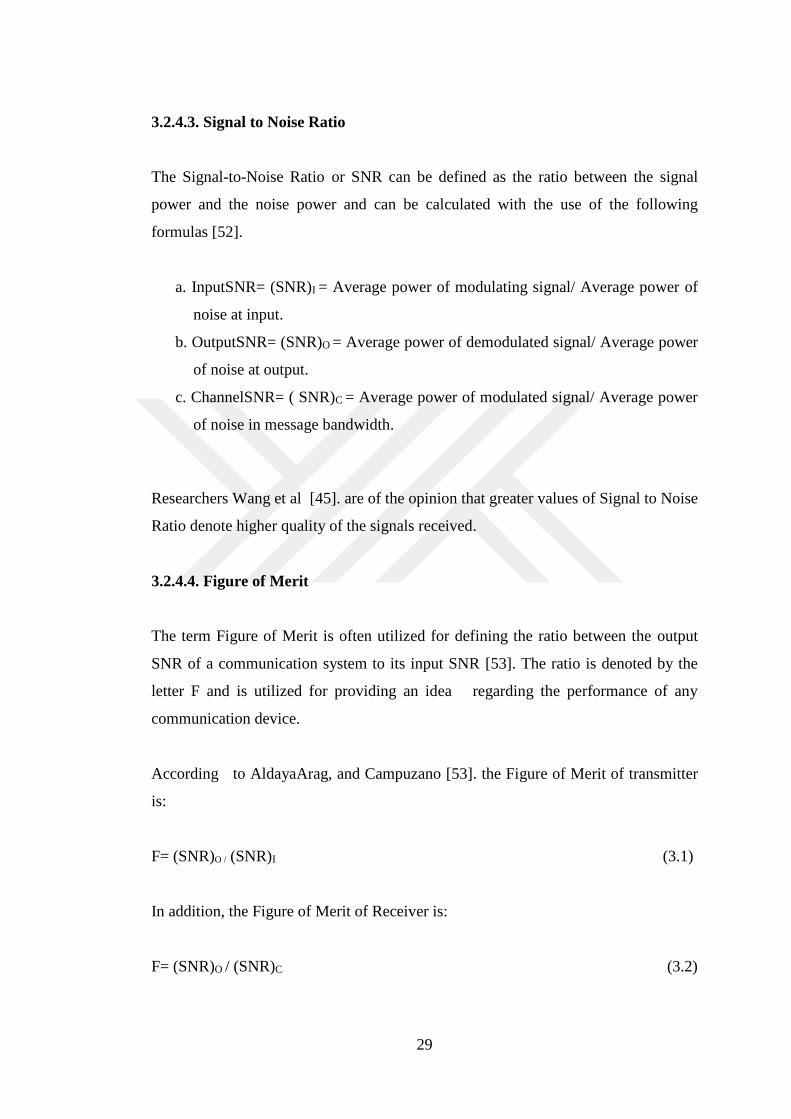
3.2.4.3. Signal to Noise Ratio
The Signal-to-Noise Ratio or SNR can be defined as the ratio between the signal
power and the noise power and can be calculated with the use of the following
formulas [52].
a. InputSNR= (SNR)I = Average power of modulating signal/ Average power of
noise at input.
b. OutputSNR= (SNR)O = Average power of demodulated signal/ Average power
of noise at output.
c. ChannelSNR= ( SNR)C = Average power of modulated signal/ Average power
of noise in message bandwidth.
Researchers Wang et al [45]. are of the opinion that greater values of Signal to Noise
Ratio denote higher quality of the signals received.
3.2.4.4. Figure of Merit
The term Figure of Merit is often utilized for defining the ratio between the output
SNR of a communication system to its input SNR [53]. The ratio is denoted by the
letter F and is utilized for providing an idea regarding the performance of any
communication device.
According to AldayaArag, and Campuzano [53]. the Figure of Merit of transmitter
is:
F= (SNR)O / (SNR)I (3.1)
In addition, the Figure of Merit of Receiver is:
F= (SNR)O / (SNR)C (3.2)

30
An interesting point has to be noted in the equation above that the Channel SNR has
been input SNR of the receiver. This is because the channel itself is the input to the
receiver device of the communication system [54].
3.2.5. Signal: Modulation and De-Modulation
In order to make any signal travel over long distances, it is essential to take
advantage of techniques that can be utilized to add strength the signal, without
making any changes in the original parameters of the same. In the following section
of the report, discussions would be made on the modulation and demodulation
techniques that are essential for the transmission of signals over long distances and
the retrieval of the same.
3.2.5.1. Signal Modulation
According to Salous [55]. an information carrying signal has to take the help of a
high frequency carrier signal when the same has to be transmitted over long
geographical distances and establish a reliable communication over the same,
provide the carrier signal does not bring about any changes in the characteristics of
the message signal. Researchers Beas et al [56]. have pointed out the fact that the
message content of a signal gets altered significantly in case the characteristics of the
same are altered under any circumstances. On the other hand, high frequency
signals have the ability to travel to large distance without being affected by external
disturbance. Thus, it is essential to take the help of such carrier signals to make a
message carrying signal to travel to long distances without incorporating any
changes in the message content of the signal [57].
Researchers Franchi, Fischer, and Weigel [51]. are of the opinion that modulation is
the very process of inducing changes in the characteristics of any carrier signal such
that becomes capable of carrying the instantaneous values of the message signal.

31
The need for modulation: As Miko and Nemeth [49]. point out, the information
carrying signals, also known as baseband signals, are not suitable for transmission
over considerable distances. In order to make them suitable for transmission over
long ranges, the strength of the same has to be increased significantly- a state
obtained by modulating it with a carrier wave of high frequency [57].
3.2.5.2. Benefits of Modulation
According to Alves and Cartaxo [50]. following are the primary benefits of the
modulation process:
a. Reduction in the size of antenna: As commented by Borah and Boucouvalas
[58]. in case baseband signal had to be transmitted over significantly long
distances, antenna of enormous sizes would have to be utilized. However, the
exploitation of modulation techniques ensures that the sizes of the antennas
are reduced significantly.
b. Increase in range of communication: In case baseband signals are transmitted
over any communication medium without any modulation, the same would not
be able to travel to significant distances without getting distorted. However,
the utilization of modulation techniques facilitates the expansion of the range
of communication [51].
c. Modulation also allows the multiplexing of signals.
d. The quality or reception increases.
e. Modulation also allows alterations in the bandwidth of the signals [57].
3.2.5.3. Signals Associated with The Process of Modulation
The following section of the report would be utilized for providing the definitions of
the various types of signals that are associated with the process of modulation.
a. The message carrying signal or the modulating signal: As commented by
Franchi, Fischer, and Weigel [51]. the signal that contains the information or
message to be transmitted is known as the message signal. As the message

32
signal is essentially a baseband signal, it has to undergo the modulation
process so as to become transmission ready. Thus, the message-carrying signal
is also known as the modulating signal [58].
b. Carrier Signal: The high frequency signal which in spite of having a certain
amplitude, phase and frequency does not have any information content is
considered as a carrier signal. The carrier signal, as Alves and Cartaxo [50].
point out, is utilized for carrying the information content of the modulating
signal to the receiver block post modulation.
c. Modulated Signal: The combination of the carrier signal with that of the
modulating signal, obtained as the result of the modulation process, is known
as the modulated signal [24].
3.2.5.4. Modulation and Its Types
Depending upon the techniques utilized for generating the modulated wave,
modulation techniques can be classified under the following groups [57].
Figure 3.8. Graphical representation of a noisy signal.
As depicted in the table above, the modulation techniques can be broadly classified
into the following types:
Types of Modulation
Continious wave modulation
Amplitude modulation
Angle modulation
Frequency modulation
Phase modulation
Pulse modulation
Digital modulation
Pulse code modulation
Delta modulation
Analog modulation
PAM PWM PPM

33
Continuous wave modulation: In this method, a sine wave of very high frequency is
utilized for the transmission of message signals to significant distances.
According to Franchi, Fischer, and Weigel [51]. continuous wave modulation
technique can be further classified into the following types:
a. Amplitude modulation: Researchers Miko and Nemeth [49]. comment that
when the amplitude of the high frequency carrier wave has to be modulated
with respect to the amplitude of the message signal, the technique is
known as amplitude modulation.
b. Angle modulation: Researchers Gandhiraj and Soman [7]. comment that when
the angle of the high frequency carrier sine wave has to be modulated with
respect to the angle of the message signal, the technique is known as Angle
modulation.
Angle modulation techniques can further be subdivided into the following types:
i. Frequency Modulation: According to Wang et al [45]. when the frequency
of the high frequency carrier sine wave has to be modulated with respect to
the message signal, the technique is to be transmitted, the process is known
as Frequency modulation.
ii. Phase Modulation: when the phase of the high frequency carrier sine wave
has to be modulated with respect to the message signal, the technique is to
be transmitted, the process is known as Frequency modulation.
iii. Pulse modulation: Researchers Franchi, Fischer, and Weigel [51]. are of
the opinion that when a “periodic sequence of rectangular pulses” are
utilized as the carrier signal for the transportation of the information
carrying signal, the technique is referred to as pulse modulation.
On the other hand, authors Selva et al [59]. illustrate that pulse modulation
techniques can further be subdivided into two types: analog pulse modulation

34
technique and digital pulse modulation technique. A detailed discussion of these two
types would be provided in the section below:
a. Analog pulse modulation technique: In case of analog modulation, if the
duration of the pulse wave is varied with respect to the information
carrying modulating signal, the technique is referred to as the Pulse
Duration/Width Modulation (PDM/PWM) [56].
In a very similar fashion, in case the position of the pulse wave is varied with
respect to the information carrying modulating signal, the technique is referred to as
the Pulse Position Modulation or the PPM [57].
Likewise, when the amplitude of the pulse wave is varied with respect to the
information carrying modulating signal, the technique is referred to as the Pulse
Amplitude Modulation or the PAM [56].
b. Digital modulation technique: In case of digital modulation, the analog signal
is at first converted into a digital signal consisting of 0’s and 1’s. According
to researchers Miko and Nemeth [49]. as the outcome of the process is a coded
pulse train, the modulation technique is known as Pulse Code Modulation or
PCM [59].
The Delta modulation technique can be considered as an improvement over the Pulse
Code Modulation technique, which involves the very same techniques that have been
discussed in the section above.
In the following section of the report, discussion would be made on Frequency
Modulation techniques and devices, such that basic knowledge utilized for the
development of the Software Defined Radio can be highlighted.

35
3.3. FREQUENCY MODULATION
Researchers Wang et al [45]. have commented that while varying the amplitude of
the carrier signal in accordance to the instantaneous values of the modulating
signal, changes can also be incorporated in the frequency of the said high
frequency carrier wave so as to make it suitable for transmission over long
distances. In fact, frequency modulation is commonly utilized for the transmission of
signals having frequencies higher than 30 MHZ, as utilized for the process of Very
High Frequency FM broadcasting or VHF FM broadcasting [60].
In addition to the high frequency FM broadcasting process, Frequency Modulation
techniques are also utilized in several other both way or duple radio
communication systems, including mobile telephony and radio systems [58].
3.3.1. Frequency Modulation: A Definition
In order to generate a frequency modulated wave, the frequency of carrier wave is
varied, so as to match the amplitude of the radio signal to be transmitted. The
following diagram provides a pictorial representation of the final output of the
frequency modulation process.
Figure 3.9. Frequency Modulation.

36
As depicted in the diagram above, during the modulation process, the output signal
makes upward and downward movements with respect to the amplitude of the
modulating signal. The extent to which the output signal makes the upward and
downward movements is considered to be of the most important parameters of a
frequency modulation process and is known as the ‘deviation’ [50].
Radio broadcasting stations that take advantage of the very high frequency range of
the radio frequency spectrum (in between 88.5 to 108 MHz) utilize deviations in the
range of -75 kHz to +75 kHz. Radio signals having such high deviation are often
termed as Wide Band FM (WBFM) [52]. The major advantage of utilizing these radio
frequency signals is that they support transmissions of very high quality: however,
the bandwidth required for the transmission process is significantly large [61].
On the other hand, the radio waves utilized for the purpose of communication are
much lesser amount of bandwidth: such signals are known as Narrow Band FM (or
NBFM) and commonly utilize deviations in the range of -3 kHz to +3 kHz [54].
The narrow band FM is not capable of supporting the high-quality transmission like
that of Wide Band FM, however the bandwidth consumption of this particular type
of signal is considerably lower than that of WBFM. Thus, Narrow Band FM signals
are utilized specifically for mobile radio/ telephonic communication purposes [62].
3.3.2. Frequency Modulators
In the following section of the report, discussions would be made on the well-known
methods that are utilized for the purpose of generating frequency modulated signals.
a. Direct method of FM generation: The diet method of FM generation involves
varying the instantaneous frequency of the high frequency carrier wave with
respect to the message content of the input signal: the variation being
performed with the help of the voltage controlled oscillator or VCO device
[46].

37
In its simplest form the modulator utilized for direct FM, generation consists of an
oscillator circuit, which in turn utilizes a varactor diode for the purpose of
determining the variations in frequency [38]. The following figure provides the
graphical representation of a Hartley oscillator being utilized FM generation using
direct methods.
Figure 3.10. FM generation (direct method) using Hartley oscillator [63].
Let, the cvo denote the capacitance of the varactor diode before the application of
the modulating signal m(t).
Therefore, after the application of the modulating signal m(t), the numerical value of
the capacitance of the varactor diode can be calculated using the following formula
[64].
CVO=CVO+kc m(t) (3.3)
where kc denotes the sensitivity of the diode
Therefore, the total capacitance of the LC circuit would be:
c(t)=cFIXED−kcm(t) (3.4)
where, cFIXED is the equivalent capacitance of co, c and vo.

38
When m(t)=0 and c(t)= cFIXED. The frequency of oscillation becomes equal to that of
the carrier frequency. The numeric value of this frequency of oscillation can be
obtained through the following equation:
fc=1/2π√.LocFIXED (3.5)
But, after the application of the modulating signal m(t), the instantaneous
frequency becomes:
fi(t)=1/2π√Lo(cFIXED−kcm(t)) (3.6)
or,
fi(t)=1/2π√ (LocFIXED(1−kcm(t)/ cFIXED)) (3.7)
Further simplifications of the above equation leads to the following equation:
fi(t)=fc+kfm(t) (3.8)
where kf=kcfc/2cFIXED
Needless to say, equation (vi) depicts the basic equation of FM waves.
b. In-direct method of FM generation:Armstrong proposed the techniques used in
the indirect method of FM generation: thus, the frequency modulator utilized
for this purpose is known as the Armstrong modulator [36].
According to Selva et al [59]. the indirect method of FM generation consists of the
following two steps:
i. Generating a narrow band FM (NBFM) from a modulating wave [41]
ii.Utilizing a frequency multiplier for the purpose of converting the
narrow band FM into wide band FM.

39
The following diagram provides a graphical representation of the various steps
utilized developing a frequency modulated signal in the indirect method [40].
Figure 3.11. FM generation (in-direct method).
3.3.3. Frequency Modulation: Advantages and Disadvantages
The following sections of the report would provide detailed information regarding
the advantages and disadvantages of frequency modulation techniques in
communication systems.
3.3.3.1. Advantages Of Frequency Modulation
a. Noise resilient: In frequency modulation systems, the information content of
the modulating signal is transmitted in form of variations in the frequency
of the carrier signal. Thus, any variations in the level of the signal (as long as
it does not become impossible for the receiver device to detect) have
negligible effect on the quality of the output audio signal [36]. On the other
hand, this very characteristic of the frequency modulated signals makes them
resilient to a wide range of signal interferences and noises. Thus,
frequency modulated waves are considered to be most suitable for both mobile
radio communication systems and radio broadcasting communication systems
[65].

40
b. Utilization of RF amplifiers: According to Franchi, Fischer, and Weigel [51].
RF transmitters can be effectively utilized to the amplification of FM
signals. The authors comment that since RF amplifiers consume much less
power than that of linear amplifiers, FM systems are much more
preferable for all mobile radio communication systems.
3.3.3.2. Disadvantages Of Frequency Modulation
Irrespective of the advantages mentioned in the section above, frequency modulated
signals have several other distinctive disadvantages over signals generated through
other modulation techniques. Some of such limitations are being enlisted in the
section below:
a. The spectral efficiency of frequency modulated systems is much less than that
of phase modulation and quadrature amplitude modulation. Thus, the former
technique cannot be utilized for efficient data transmission systems [53].
b. The demodulator utilized in the receiving ends of the FM communications
systems are much more complex and expensive than those utilized in case of
other modulation techniques [57].

41
3.4. FREQUENCY MODULATION (FM) RADIO SYSTEMS
As discussed in the sections above, frequency modulation is widely utilized in
television and radio communication systems. In the following section of the report,
discussions would made with the aim of providing the audience with the very
basic concepts of the transmitters and receivers utilized in FM communication
systems.
3.4.1. The FM Transmitter
According to Franchi, Fischer, and Weigel [51]. the entire unit that consider a
incoming message containing signal as the primary input and processes the
same to generate a FM modulated signal, ready for transmission, should be
considered as the transmitter unit of the radio communication system. The
following image provides a graphical representation of the six core elements of a FM
transmitter:
Figure 3.12. Block Diagram of a FM Transmitter.
The transmission of a FM signal occurs through the following stages:
a. In the very first step, the audio signal generated by the microphone is fed into
the pre-amplifier. The pre-amplifier in turn amplifies the audio signal by
boosting the incoming modulating signal to the next higher level [60].

42
b. The amplified signal is then fed into a high pass filter. The high pass filter
performs the function of the pre-emphasis network and facilitates the
process of filtering the noise signals present in the incoming signal [26]. This
particular stage of the transmitter circuit essentially improves the signal to
noise ratio of the modulating signal.
c. The output of the high pass filter is then passed to the FM modulator circuit.
The oscillator circuit present within the FM modulator circuit generates the
high frequency carrier wave and modulates it in accordance to the
instantaneous values of the modulating signal [58].
d. The modulated signal generated by the FM modulator circuit is then passé
through a frequency multiplier which helps in increasing the operating
frequency of the modulated signal.
e. Last but not the least, the RF power amplifier is utilized for enhancing the
power level of the signal. Transmission of the amplified signal occurs
through the antenna attached with the transmitter block [56].
3.4.2. The FM Receiver
According to Johnson et al [57]. the entire unit that considers a incoming modulated
signal as the primary input and processes the same to generate an audio signal as
output should be considered as the transmitter unit of the radio communication
system. The following image provides a graphical representation of the five core
elements of a super heterodyne FM receiver:
Figure 3.13. Block Diagram of a super heterodyne FM receiver.
The super heterodyne FM receiver operates in the following manner:

43
Step 1: The input signal to the receiver circuit (as received by the antenna) is
primarily passed on to the RF Tuner Section, which essentially selects the
frequency that would be demodulated by the receiver [45]. The RF Tuner
Section also takes part in the task of tuning the RF filter and the local
oscillator associated with the receiver circuit [57].
Step 2: The output of the RF Tuner Section is fed to the RF-IF converter, which
performs the task functionalities of a signal mixer. The RF-IF converter
essentially consists of a local oscillator: the RF-IF converter thus mixes the
incoming modulated signal with the constant frequency generated by the
local oscillator [60]. The resultant frequency is often termed as the
Intermediate Frequency or the IF [46].
Step 3: The IF filter is basically a band pass filter that helps in the elimination
of all the interference or noises present in the incoming signal, thus
improving the Signal to Noise Ratio (or SNR) of the incoming signal [22].
Step 4: The demodulation of the incoming signal is conducted in this stage. It is
quite interesting that the process utilized for the demodulation is very similar
to the modulation process utilized in the transmitter side [64].
Step 5: The output of the demodulator is fed to the audio amplifier as enhance the
audio levels of the output signal [37].

44
CHAPTER 4
METHODOLOGY
4.1. METHODOLOGY
The following section of the thesis report would be dedicated solely to the discussion
of the methods that have been utilized in demonstrating the practical applications of
the software define radio system. The discussions made in chapters 2 and 3 of the
report have lead the identification of the most essential hardware and software
elements requited for the implementation of any software define radio system, out
of which the hardware parts, namely personal computing devices with high
processing power were readily available in the laboratory.
However, in order to receive the signals with the help of the high-end processors
included in the computing devices, effective software modules capable of
receiving and transmitting radio signals had to be installed. Two well known
software modules were utilized for the same, namely the HDSDR program and the
SDRSharp program. On the other hand, the GNU radio platform was utilized for the
process of transmitting the radio signals processed by the computing device. It is
worth mentioning that the HackRF One, a well known open source SDR platform
was also utilized in the project.
Detailed discussions on the above mentioned software modules would be made
in the sections below, along with the step by step process in which the receival
and transmission of radio signals have been achieved successfully, along with the
preliminary requirements of these modules and the circuit utilized for the purpose.

45
4.2. DESIGN DIAGRAM
In this section of the report, discussions would be made on the software modules
utilized for receiving and transmitting the radio signals, along with the hardware
elements on which the software modules were run.
4.2.1. Hardware Elements Utilized In The Project: The Hackrf One Bundle
The HackRF One is one of the most well known inbuilt Software-Defined Radio
platforms that facilitate the accurate and fast transmission of signals in the radio
frequency range. The hardware platform has been designed in manner such that it
is capable of receiving and transmitting radio signals in the range of 1 MHz to 6
GHz.
According to the information available on the official product page of HackRF One
Bundle http:// hackerwarehouse. com/ product/ hackrf-one-kit/), the device acts as an
open source platform capable of transmitting radio signals in the range of 1 MHz to
6 GHz, besides having the capability of operating like that of a USB peripheral. It
has also been mentioned in the very same page that this particular hardware
platform can be programmed according to the specific requirements of any project,
thus making it suitable for use as a standalone device.
On the other hand, according to B. Bloessl [4]. the capability of the HackRF One
Bundle to operate as a USB peripheral makes it possible to utilize the device like
that of the sound card of any personal computing device. The device has the
capability of processing radio signals besides transforming them into digital signals
and vice versa, thus supporting the integration among the various phases associated
with communication networks or systems of large scale. Needless to say, the device
is widely utilized for the purpose of testing, developing, improvising and modifying
radio communication systems.
Researchers Klumperink and Nauta [66]. have highlighted yet another aspect of this
particular open source platform that make it the primary choice of radio signal

46
processing works. The authors comment that at present , we are being surrounded
by a wide variety of digital technologies and radio waves, like that of WiFi,
broadcasting stations, smart phones, bluetooth, IT infrastructures and GPS: the
HackRF One is one such open source software defined radio platform that has
the unique capability of interacting all of the above. In fact , the standalone
hardware platform has been provided with the capacity of trans-receiving a vast
majority of the wireless signals that are utilized for the purpose of
communication in the modern age: the key idea behind including such capabilities
being the development of one such pen source platform that can be utilized for
providing assistance to researchers and communication engineers in implementing
more effective and acute wireless radio communication systems [65].
The HackRF One Bundle consists of essentially the HackRF One hardware platform
and an ANT500 Telescopic Antenna. The ANT500 Telescopic Antenna is capable
of receiving and transmitting radio frequencies lying in the range of 75 MHz to 1000
MHz. The said antenna has a resistance of 50 ohm: the total length of the antenna
is 20cm (when collapsed) and 88 cm when extended fully.
The features of the other component e of the bundle, that is the HackRF One
hardware platform itself, is being include in the section below:
Characteristic features of the HackRF One platform:
1. Transmitting or receiving any radio signal that lies within the range between 1
MHz and 6000 MHz
2. Half-duplex transceiver
3. Supports a maximum sample rate of 20 Maps
4. Supports 8-bit quadrature samples : both 8-bit Q and 8-bit I
5. Supports a High Speed USB Interface
6. Drives Power through USB bus
7. compatible with SDR#, GNU Radio, , and several other similar platforms
8. The RX and TX baseband filter and gain are software-configurable
9. antenna port power (50 mA at 3.3 V) is software-controlled

47
10. Includes SMA female antenna connector
11. Includes SMA female clock input and output for supporting synchronization
12. Includes convenient buttons that can be utilized for the purpose of
programming
13. includes internal pin headers that can be utilized for further expansion
14. Weight of the device: 1 lbs
15. Dimension of the hardware setup: 6 inches x 4 inches x 1 inch
16. Developed and marketed by: Great Scott Gadgets
Figure 4.1. The HackRF One Bundle.
Figure 4.2. The HackRF One hardware.
Figure 4.3. The ANT500 Telescopic Antenna included in the HackRF One Bundle.

48
Figure 4.4. The internal circuit of the HackRF One.
Advantage of HackRF One platform over other similar hardware platforms:
Researcher Fähnle [67].is of the opinion that there exist several other open source
software defined radio platforms that clam to provide similar advantages like that of
the HackRF One: the USRP and the BladeRF being two of the most well-known
ones. However, the authors have also pointed out the fact that BladeRF and other
similar platforms are capable of receiving and transmitting radio signals in the range
of 1 Mhz to 3.8 GHz only. Besides this, the said platforms (USRP and the BladeRF)
still operate on Schematics and Host Code. These two platforms are also priced at
a much higher range: from 675 USD to 1100 USD and up [66].
Therefore, the primary advantages of using the HackRF One platform over other
similar hardware platforms can be outlined as the following:
1. Available at a very low cost as compared with the competitors (HackRF One is
currently available at price of 330 USD only)
2. Capability of transmitting and receiving radio signals lying in within a larger
domain (from 1 MHz up to 6 GHz)
3. Being open source, the platform need not rely on any other software platform for
efficient operations [67].

49
4.2.2. The Software Platform Utilized in This Project
As mentioned in section 4. 1 of this chapter, for the process of transmitting and
receiving the radio signals, three particular software modules were utilized the
HDSDR program and the SDRSharp program were utilized for the purpose of radio
signal receiving, whereas the GNU radio was utilized for the process of radio
signal transmission.
In the following sections of the chapter, discussions would be made on each of
software modules that have been utilized for the process of transmission and receival
of radio signals.
4.2.2.1. Software Modules Utilized for Receiving Radio Signals
The HDSDR program
The HDSDR program is an open source, freeware SDR (Software defined Radio)
program that has been designed specifically to be installed on the windows platform.
The typical applications that are supported by this software module include the
following: Radio listening, SWL, Ham Radio, Radio Astronomy, Spectrum analysis
and NDB-hunting.
The current version of HDSDR is supported by a wide range of windows-based
platforms, including the Microsoft Windows 2000, Microsoft Windows XP,
Microsoft Windows Vista, Microsoft Windows 7, Microsoft Windows 8, Microsoft
Windows 8.1 and the latest Microsoft Windows 10. It is worth mentioning that the
HDSDR is essentially an advanced version of the widely known Winrad designed
and developed by Alberto di Bene.
The key features of the HDSDR program are being outlined in the following section
of the thesis.

50
Characteristic features of the HDSDR program
1. The waterfall display and large spectrum for each input and output signal is
available separately
2. It is possible to and is optically zoom the waterfall and the AF & RF spectrum to
fit the width of the window, the entire process being independent of the FFT
resolution bandwidth (RBW)
3. The screen area can be efficiently and flexibly used (from 640x480 (Netbooks) up
to 8k)
4. The software module supports extremely low-speed waterfall, which is helpful for
the detection of noise patterns and/ or short-wave condition monitoring
5. The following demodulation modes are supported: AM, FM, SSB, ECSS and CW
6. The basic transmit (TX) supports functionality in the following modes SSB, FM,
AM, & CW
7. The I/Q modulated signal pair this is utilized for the TX input signal (or the
Microphone signal) is re-produced on the output of the TX or the microphone
8. The software module under consideration supports the following features: noise
reduction, squelch, noise blanker, anti-alias filter, automatic notch filter adjustable
band pass filter and up to 10 other notch filters that are manually adjustable
9. The software module under consideration also supports playback and record RF,
AF and IF WAV files, along with scheduled recording for the same.
10. The HDSDR program supports transmission and receival of radio signals in the
following bands: Ham Bands, Frequency Manager for Eibi, User frequency lists,
Radio Bands, etc
11. The HDSDR program supports DDE client for Ham Radio Deluxe, WXtrack,
Orbitron, SatPC32, PstRotator (Howto) and Wisp
12. The HDSDR program includes Omni-Rig support (CAT) for controlling
additional hardware
13. The HDSDR program supports several other hardware through the utilization of
the Alberto's (I2PHD) ExtIO DLL interface
14. ExtIO frequency options for Downconverter, IF-Adapter, Upconverter,
calibration and Under sampling are also supported by the HDSDR program

51
15. All program options available with the HDSDR can be easily stored and loaded
by creating specific "profiles": this feature makes it easier to utilize various
receivers
16. The HDSDR program has inbuilt options for autocorrelation and cestrum
display of the demodulated audio waves
17. Some of the command line options available with the HDSDR program facilitates
the process of profile management
The SDRSharp (SDR #) program
The SDRSharp (or the SDR #) program is small, effective, simple an intuitive
personal computer based Digital Signal Processing application that supports the
functionalities of a software defined radio. The entire application has been
developed in C# (hence the name SDR #) and currently supports the following
devices:
a. Any SDR front end that is sound card based
b. FiFiSDR
c. FUNcube Dongle
d. FUNcube Dongle Pro+
e. I/Q wav files
f. LazyDog’s LD-1
g. RTL2832U / RTLSDR (external)
h. SDR-14
i. SDR-4
j. SDR-IQ
k. SoftRock
The SDRSharp (or SDR #) program was also utilized for developing a software
defined radio: the detailed description of the steps and processes that were utilized
in the same would be discussed in section 4.4 of the report. It is worth mentioning
that the RTL-SDR dongle R820T/R820T2 was purchase and utilized for the said
setup.

52
4.2.2.2. The Software Modules Utilized for Receiving Radio Signals: The GNU
Radio
According to authors Gandhiraj, Ram, and Soman [7]. the GNU Radio is essentially
an open source and free software toolkit that incorporates a range of signal
processing blocks that are essential for supporting the functional operation of
software defined radios. The researchers have also highlighted the fact that the
GNU radio can be integrated with readily available inexpensive external radio
frequency hardware or can also be utilized within a simulation like environment that
does not include any hardware setup.
The GNU radio platform was utilized with the aim of developing a software defined
radio: the details of this design phase, along with the procedure utilized for the
installation of the GNU radio would be discussed in brief in section 4.4 of the
report.
4.3. REQUIREMENTS
The hardware elements that were essential for the installation and implementation of
the software modules utilized in this project are being enlisted in The following
points :
1. The HackRF One hardware: For the development of the SDR module
1.1 - Transmitting or receiving any radio signal that lies within the range between
1 MHz and 6000 MHz
1.2 - Half-duplex transceiver
1.3 - Supports a maximum sample rate of 20 MSps
1.4 - Supports 8-bit quadrature samples: both 8-bit Q and 8-bit I
1.5 - Supports a High-Speed USB Interface
1.6 - Drives Power through USB bus
1.7 - compatible with SDR#, GNU Radio, and several other similar platforms

53
2. Microsoft windows platform: For running the HDSDR program
2.1 - Microsoft Windows 7, 64-bit operating system
3. Microsoft windows platform: For running the SDRSharp (SDR #) program
3.1 - Microsoft Windows 10, 64-bit operating system, Microsoft .NET 4.6
redistributable
4. Linux OS system: For running the GNU radio
4.1. - N/A
4.4. DESIGN
4.4.1. Installing and Running the HDSDR Software
The primary characteristics of the HDSDR software have been already highlighted in
the section above. In the sections below, in-depth discussions would be made on the
step that have been utilized for the installation of the HDSDR platform and receiving
radio signals with the help of the same.
1. Installing the HDSDR Software.
The HDSDR software was installed in the personal computer through the following
steps:
a. Microsoft based Windows 7 was installed in the PC: however, the HDSDR
program is also supported by all higher versions of windows including
Windows 8, 8.1 and 10.
b. An Si570-based Local Oscillator was attached to the RX Rig. Besides this,
the I and Q outputs of the rig were wired in accordance to the build
instructions.
c. The HDSDR software module was downloaded from the website link
http://www.hdsdr.de/

54
d. The downloaded software was then installed with all default options
e. The installation location of the HDSDR was noted.
f. In the next step, the CFGSDR was downloaded from the website link
http://pe0fko.nl/CFGSR/#download. The program was installed with all
default options, and the installation location was also noted. Once the
installation was completed, the said location was visited with the aim of
copying the file name extIO.dll. This particular file was the pasted at the
installation folder of the HDSDR program, so as to ensure efficient
communication with the later.
2. Configuring the HDSDR.
The HDSDR was configured in the PC through the following steps:
a. The program was initiated by clicking on the HDSDR icon present on the
desktop
b. Once the program was initiated, the control panel option were manipulated
in the following manner:
i. Soundcard selection: The soundcard option was clicked on, after which
the RX soundcard option was elected (I and Q were selected for input
whereas the Output option was selected for speaker).
ii. Bandwidth selection: In the bandwidth dialogue box, 48000 was entered
as the input bandwidth, the default option was selected for the output. As
a result of these selections, a tuning range of -48 kHz to +48 kHz was
achieved as the Local Oscillator frequency or the central frequency.
iii. Option selection: In the dialogue box for option selection, the Soft rock
Si570 was selected as the input. Next, the option sited as “Swap I and Q
Channels for RX Input” was also selected, with the aim of setting the
USB and LSB of the incoming SSB signal [67].

55
The following figures provide an insight into the various options that were selected
during the configuration phase of the HDSDR.
Figure 4.5. The HDSDR interface.
Figure 4.6. Selecting the soundcard on the HDSDR interface.

56
Figure 4.7. Selecting the sampling rate on the HDSDR interface.
The Start (F2) button present on the HDSDR interface was clicked on for starting the
HDSDR program. The very same key was also utilized for stopping the program.
4.4.2. Installing and Running the Sdrsharp (SDR #) Program
SDRSharp (SDR #) software was installed in the personal computer through the
following steps:
a. The R820T/R820T2 dongle was purchased and connected to a personal
computer running on Microsoft windows 10. It is worth mentioning that since
the Microsoft .NET 4.6 redistributable is essential for the installation of the
SDRSharp (SDR #) program, it was made sure that the same has been
installed in the PC.
b. The SDR Software Package available at www.airspy.com was downloaded.
The zipped file thus obtained was extracted or unzipped so as to facilitate the
further processes of installing the software.
c. Once the extraction of the downloaded zipped file was completed, the install-
rtlsdr.bat file was clicked on (double click). Clicking on the said file resulted
in the generation of a command prompt which ultimately lead to the
successful download of all the drivers required for the functional
operations of the SDRSharp (SDR #) program. The command prompt
closed down automatically after several driver files, including zadig.exe and
rtlsdr.dll were downloaded in the SDRSharp (SDR #) directory. However, in

57
case the same are not downloaded automatically, manual driver installation
can also be performed.
d. The R820T/R820T2 dongle was connected to the PC: however, none of the
software packages that were provided with it were installed. Instead, the
zadig.exe file that was downloaded in the SDRSharp (SDR #) directory was
right-clicked on and the ‘Run as administrator’ option was chosen.
e. In Zadig, ‘Options->List All Devices-> Bulk-In, Interface (Interface 0)’ were
selected.
f. In the next step, the ‘replace driver’ option was selected, followed by the
installation of the WinUSB driver.
g. The SDRSharp.exe was opened. The drop-down box in the ‘source tab; was
set to RTL-SDR (USB).
h. The SDR Sharp started operating once the play button was pressed.
The following figures provide an insight into the various processes that were utilized
during the installation and configuration phase of the SDR Sharp.
Figure 4.8. The SDR Sharp interface.
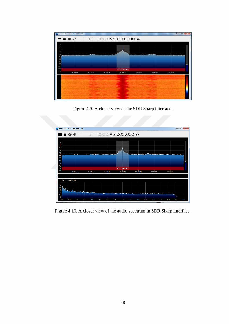
58
Figure 4.9. A closer view of the SDR Sharp interface.
Figure 4.10. A closer view of the audio spectrum in SDR Sharp interface.

59
Figure 4.11. A closer view of the FM MPX spectrum in SDR Sharp interface.
Figure 4.12. A closer view of the IF spectrum in SDR Sharp interface.

60
Figure 4.13. IF+ FM MPX+ FM+ Audio spectrum in SDR Sharp interface.
Figure 4.14. A closer view of the receiver functionality of the SDR Sharp interface.
4.4.3. Installing And Running The GNU Radio Program
A. Installing the GNU radio
According to authors S. Bassam et al [3].the most recommended manner of installing
the GNU radio is to do the same from the gnuradio package included in the standard
repositories of the Linux distributor.

61
In the project under consideration, both the Ubuntu, Fedora and Debian platforms
were utilized for implementing the GNU radio. In case of the Ubuntu platform, the
following command was utilized for the purpose of package installation:
>> $ apt-get installs gnuradio
The installation process was quite similar in the Debian platform. On the other hand,
in order to install the GNU radio package, the following command had to be run:
>> $ yum install gnuradio
B. Observing GNU Radio Properties
After the installation of the GNU radio, we started with observing the various inbuilt
functionalities included in the package. Some of the features that we were capable of
identifying have been provided in the section below:
Figure 4.15. Observing the Audio Gain property of GNU radio.

62
Figure 4.16 Observing the Audio Source property of GNU radio.
Figure 4.17. Observing the frequency property of GNU radio.
Figure 4.18. Observing the IF Gain property of GNU radio.

63
Figure 4.19. Observing the Low pass filter property of GNU radio.
Figure 4.20. Observing the multiply const property of GNU radio.
Figure 4.21. Observing the WBFM Transmitter property of GNU radio.

64
Figure 4.22. Observing the rational_resampler_ 1 property of GNU radio.
Figure 4.23. Observing the rational_resampler_ 2 property of GNU radio.
Figure 4.24. Observing the RF Gain property of GNU radio.

65
Figure 4.25. Observing the scope plot property of GNU radio.
Figure 4.26. The wave File Source.
Figure 4.27. The WBFM transmitter.

66
Figure 4.28. Observing the WX GUI SCOPE SiNK property of GNU radio.
Developing the SDR circuit using the inbuilt GNU Radio Properties
After observing the inbuilt communication blocks included within the GNU radio
package, we proceeded with the development of the software defined radio circuit.
The communication blocks that were reviewed earlier (screenshots attached in the
section above) were utilized in the same, and the circuit diagram is being attached in
the section below.

67
Figure 4.29 The SDR circuit diagram as developed in the GNU radio platform.
As demonstrated in the figure above, the contents of the WAV source file is fed into
the Multiply Constant block. The outputs of this block then pass through the low
pass filter and the rational resampler 1. The output of the rational resampler 2 is then
fed into the WBFM transmitter and the rational resampler 2. The output signal from
the rational resampler 2 is finally passed to the WX GUI Scope Sink and the
osmocom Sink.
WAV File Source:
It creates a data source from the audio wave file. The file can be captured in GNU
radoop with the WAV File Sink that is created in the audio editor like Audacity with
proper WAV options in MATLAB utilizing the wavwrite command It specifies if it
is required to play continuously in the loop or not. It makes specification in the
number of channels from the particular file. The Wav files are usually mono channel
and represents single data stream as well. On the other hand, representing single data

68
stream and including in the phase as well as elements of the complex system are
included in the channel. It helps to develop the phase and elements for the service.
Low Pass Filter: The filter is convenience wrapper for FIR filter as well as firdes the
taps that generates functions. The sample rate and cut off frequency as well as
transitions of width are included in Hertz. The beta parameter applies to Kaiser
Window. On the other hand, FIR tupes specifies the data type of input as well as
output streams that are included in the option of decimation. Input as well as output
streams are complicated with the options for decimating the output. Decimation and
interpolation are selected through FIR type parameter. Decimation as well as
interpolation are selected with the help of FIR type parameter and obtain the filter.
Rational Resampler: It is combined interpolator as well as decimator. The particular
block is utilized in order to convert from a sample rate to another for long time
related through ratio. The type specifies data type of input as well as output streams.
There are complicated systems that specify the type of filter, which can be applied.
Input and output streams are complicated and antialiasing filter, which has
complicated taps. Input as well as output streams are complicated and have filter for
real taps.
Audio Source: It represents audio input hardware within the flow graph of GRC, the
signal needs to be included in the input of microphone on the front level of the
system. It is required to adjust the input obtain for best possible performance. The
sample rate makes specification for the sampling rate for using. The rates of
sampling are usually supported through the audio hardware. 48 KHz makes
specification for sampling rate to utilize. Outputs specify the number of value for
mono input.

69
CHAPTER 5
CONCLUSION
5.1. CONCLUSION
A software defined radio or a SDR is often described as that radio communication
system that takes the advantage of specific software-based modules for the receival
and transmission of radio signals instead of taking advantage of hardware-based
signal receiver and transmission systems. The primary aim of conducting this
academic research work was to identify the utilities of a software define radio
system in the modern communication systems, besides gaining a hands –on
experience on the practical implementation of software defined radio systems. It is
worth mentioning that the sole objective of conducting this research work was
implement a software defined radio communication system on HACKRF ONE, a
well-known embedded hardware system that has specifically been developed for the
purpose of software based FM transmission..
With the aim of obtaining background information regarding the operational
functionalities of a software defined radio communication system, the first and
foremost activity that was undertaken was to review as many as 37 literary and
scholarly articles that have been published in the recent past. An in-depth study of
the said scholarly papers and articles facilitated the collection of information in
certain specific topics of the study, namely the modulation and demodulation
techniques/ methods utilized for r receival/ transmission of FM signals using SDR,
the techniques utilized for the implementation of communication protocols using
Software Defined Radio, along with the other application specific uses of thee
system and the applications of SDR in domains other than radio frequency
communication.

70
In the next phase, a detailed study of the theoretical aspects of the project was
conducted with the aim of gaining further information regarding the concept of FM
transmission. The theoretical background study facilitated the process of identifying
the essential elements of any communication system, along with the fundamental
theories associated with the receival and transmission of frequency modulated
signals. This study also provide us with in-depth information regarding the hardware
elements (transmitter and receivers) that form an integral part of any
communication system and the steps through which these elements operate.
Based on the information gathered from the literature review and the theoretical
background study phase, attempts were made to practically implement a software
defined radio signal capable of receiving and transmitting FM signals. The
HACKRF ONE hardware set up was connected to the personal computers available
in the computer laboratory of the institute and three well known software modules
(the HDSDR Software, the SDR Sharp and the GNU radio) were utilized for the
transmission and receival of FM waves.
In the following section of the thesis report, discussions would be made with the
aim of shedding some light of the efforts made towards achieving the primary
objectives of the project. It is worth mentioning that the discussions would be to
identify the extent to which the objectives of this academic project have been
achieved through the activities undertaken during the life cycle of the study.
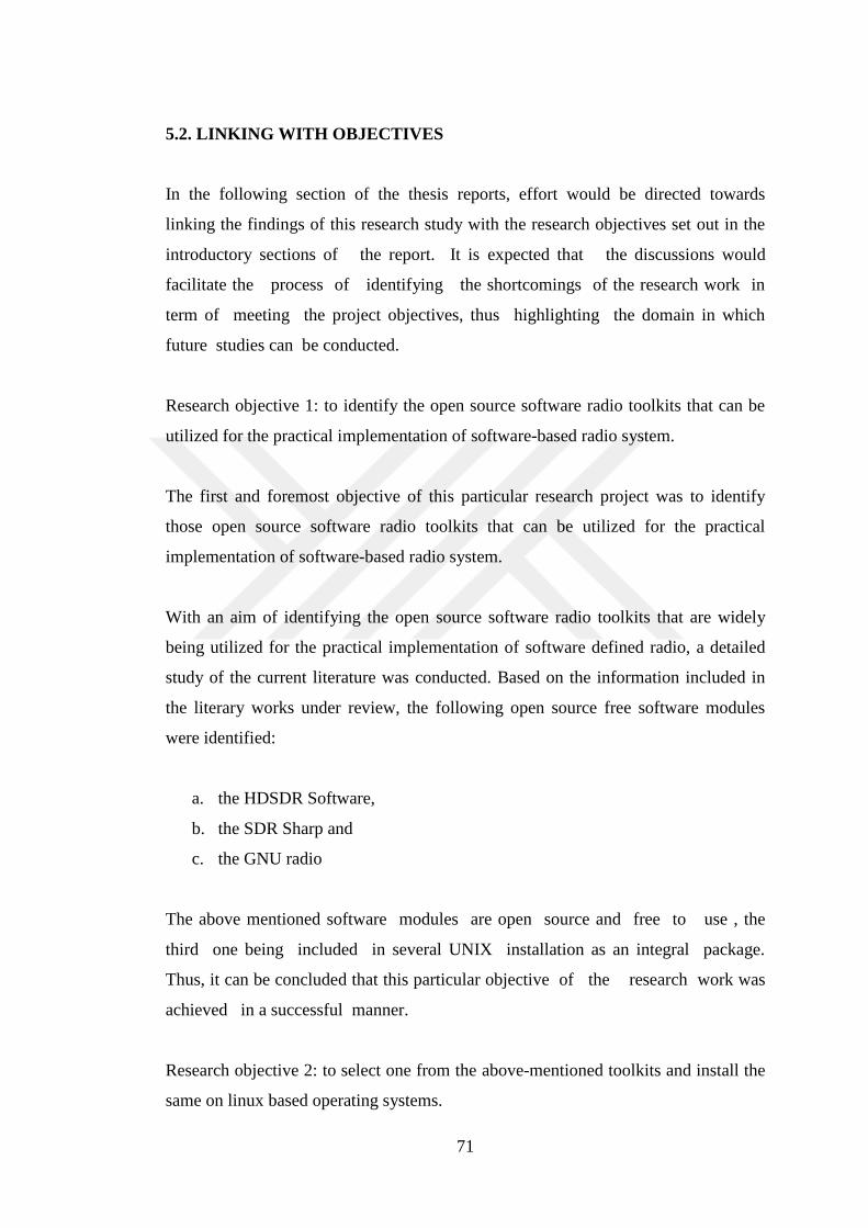
71
5.2. LINKING WITH OBJECTIVES
In the following section of the thesis reports, effort would be directed towards
linking the findings of this research study with the research objectives set out in the
introductory sections of the report. It is expected that the discussions would
facilitate the process of identifying the shortcomings of the research work in
term of meeting the project objectives, thus highlighting the domain in which
future studies can be conducted.
Research objective 1: to identify the open source software radio toolkits that can be
utilized for the practical implementation of software-based radio system.
The first and foremost objective of this particular research project was to identify
those open source software radio toolkits that can be utilized for the practical
implementation of software-based radio system.
With an aim of identifying the open source software radio toolkits that are widely
being utilized for the practical implementation of software defined radio, a detailed
study of the current literature was conducted. Based on the information included in
the literary works under review, the following open source free software modules
were identified:
a. the HDSDR Software,
b. the SDR Sharp and
c. the GNU radio
The above mentioned software modules are open source and free to use , the
third one being included in several UNIX installation as an integral package.
Thus, it can be concluded that this particular objective of the research work was
achieved in a successful manner.
Research objective 2: to select one from the above-mentioned toolkits and install the
same on linux based operating systems.

72
The second objective that was outlined in the introductory section of the thesis report
was to select one from the identified software based radio system toolkits and install
the same on Linux based operating systems. It was already mentioned the section
above that the literature review and background study work led to the identification
of as many as 3such open source freeware tools that can be effectively utilized for
the practical demonstration of software-based radio system: the tools being the
following –
a. the HDSDR Software.
b. the SDR Sharp Software.
c. the GNU radio Software.
Out of the above-mentioned software modules, the GNU radio was found to be
available with almost all UNIX installations as an integral package.
Three different variations of the UNIX platform were utilized with the aim of
installing the GNU radio package, detailed discussion regarding which have been
included in section 4.4.3 of the report.
Thus, it can be said that this vey objective of the project was also met with.
Research objective 3: to demonstrate the process of installing the radio software
module in a step by step manner, and describe the manner in which the fm signals are
obtained and processed in the said module
The last and final objective of the academic research work, as outlined in the
introductory section of the thesis report was to demonstrate the process of installing
the radio software module in a step by step manner and describe the manner in which
the FM signals are obtained and processed in the said module.

73
It has already been mentioned in the preceding sections of the report that the
literature review and background study conducted during the very initial stages
of the project led to the identification of the under mentioned software tools:
a. the HDSDR Software,
b. the SDR Sharp and
c. the GNU radio
Out of the above-mentioned software modules, the first two utilized specifically for
the purpose of receiving FM transmissions. These software modules were installed
on personal computers supported by Microsoft based operating systems and the
detailed description of the steps followed for the installation and utilization of the
same in receiving frequency modulate signals have been provided in section 4.4.1
and 4.4.2 of the thesis report.
On the other hand, the GNU radio package was installed on three different types of
UNIX based Operating systems, namely UBUNTU, Debian and Fedora and the
details of the same have been discussed in section 4.4.3 of the report. Besides this,
a detailed description of the SDR circuit designed on the GNU radio platform has
also been included in this section.
Thus, it can be said that the third objective of the project was achieved in a
successful manner.
5.3. FUTURE RESEARCH
The discussions made in the sections above are indicative of the fact that the core
objectives of the project, namely the identification of the open source software
radio toolkits that can be utilized for the practical implementation of software based
radio system, the selection one from the above mentioned toolkits and install the
same on Linux based operating systems and the demonstration of the process of
installing the radio software module in a step by step manner have successfully
been achieved through all the activities conducted during the lifecycle of the

74
project. However, the following domains can be considered for conducting
research work in the future:
a. Attempts can be directed towards achieving successful receival and
transmission of frequency modulated radio wave through all the SDR
toolkits that have been identified and utilized in this project.
b. The information collected from the literature survey indicates that software
defined radio based cellular networks can be utilized for the finding
solutions to a wide range of issues that are currently experienced with LTE
cellular data networks. Research works can be conducted in the future with
the aim of implementing such SDN cellular platforms.

75
REFERENCES
1. B. Bloessl, C. Leitner, F. Dressler, and C. Sommer, “A GNU Radio-based IEEE
802.15.4 testbed,” Proc. 12. GI/ITG KuVS Fachgespräch Drahtlose Sensornetze
(FGSN 2013): 37–40 (2013).
2. R. Chavez-Santiago, A. Mateska, K. Chomu, L. Gavrilovska, and I. Balasingham,
“Applications of software-defined radio (SDR) technology in hospital
environments,” in Proceedings of the Annual International Conference of the
IEEE Engineering in
3. S. Bassam et al., “A Generic Architecture for Smart Multi-Standard Software
Defined Radio Systems,” Proc. SDR ’09 Tech. Conf. Prod. Expo., 1-4. (2009).
4. B. Bloessl, M. Segata, C. Sommer, and F. Dressler, “Full Paper : An IEEE 802 .
11a / g / p OFDM Receiver for GNU Radio,” 2nd ACM SIGCOMM Work.
Softw. Radio Implement. Forum (SRIF 2013): 9–15 (2013).
5. J. R. Humphries and D. C. Malocha, “Software defined radio for passive sensor
interrogation,” in 2013 Joint European Frequency and Time Forum and
International Frequency Control Symposium, EFTF/IFC 2013, 270–273
(2013).
6. D. a. Gioia, K. G. Corley, and A. L. Hamilton, “Seeking Qualitative Rigor in
Inductive Research: Notes on the Gioia Methodology,” Organ. Res. Methods, 16
(1), 15–31 (2012).
7. R. Gandhiraj, R. Ram, and K. P. Soman, “Analog and digital modulation toolkit
for software defined radio,” Procedia Eng., 30, 1155–1162 (2012
8. C. Kothari, R. Kumar, and O. Uusitalo, Research Methodology. (2014).
9. M. Pedler, “Reflexive methodology: new vistas for qualitative research,” Action
Learn. Res. Pract., 9, March 2014, 83–87 (2012).
10. J. Gozalvez, M. Sepulcre, and R. Bauza, “Impact of the radio channel modelling
on the performance of VANET communication protocols,” Telecommun. Syst.,
50 (3): 149–167 (2012).

76
11. Youth and Information and Communication Technologies (ICT) World YOUTH
Report, 2003
12. Prabaswara, “GNU Radio Based Software-Defined FMCW Radar for Weather
Surveillance Application,” (144): 227–230 (2011).
13. J. Ralston and C. Hargrave, “Software defined radar: An open source platform
for prototype GPR development,” 2012 14th Int. Conf. Gr. Penetrating Radar,
GPR 2012, no. June, 172–177 (2012).
14. T. W. Rondeau, T. O. Shea, and N. Goergen, “Inspecting GNU Radio
Applications with ControlPort and Performance Counters,” in Proceedings of the
second workshop on Software radio implementation forum, 2013, 65–70
(2013).
15. J. Gray, “Capstone Senior Design Project Report 2, (2016).
16. Kumar and S. Noghanian, “Wireless channel test-bed for DSRC applications
using USRP software defined radio,” in IEEE Antennas and Propagation
Society, AP-S International Symposium (Digest), 2013, 2105–2106 (2013).
17. S. Karlin, “Software-defined radio, part II,” IEEE Spectr. 50 (9),24–25 (2013).
18. S. J. Olivieri, J. Aarestad, L. H. Pollard, A. M. Wyglinski, C. Kief, and R. S.
Erwin, “Modular FPGA-based software defined radio for CubeSats,” in IEEE
International Conference on Communications, 2012, 3229–3233 (2012).
19. Wireless Innovation Forum, “What is Software Defined Radio,” Forum Am. Bar
Assoc., 6 (2011).
20. D. A. Scaperoth, “Configurable SDR Operation for Cognitive Radio Applications
using GNU Radio and the Universal Software Radio Peripheral,” (2007).
21. M. B. Sruthi, M. Abirami, A. Manikkoth, R. Gandhiraj, and K. P. Soman, “Low
cost digital transceiver design for Software Defined Radio using RTL-SDR,”
2013 Int. Multi-Conference Autom. Comput. Commun. Control Compress.
Sensing, 2013 iMac4s, 852–855 (2013).
22. K. Von Ehr, W. Neuson, and B. E. Dunne, “Software defined radio: Choosing the
right system for your communications course,” ASEE Annu. Conf. Expo. Conf.
Proc., 2016–June (2016).

77
23. B. Szlachetko and A. Lewandowski, “A Multichannel Receiver of the
Experimental FM Based Passive Radar Using Software Defined Radio
Technology,” Intl J. Electron. Telecommun., 58 (4): 301–306 (2012).
24. N. B. Truong and C. Yu, “Investigating latency in GNU Software Radio with
USRP embedded series SDR platform,” in Proceedings - 2013 8th International
Conference on Broadband, Wireless Computing, Communication and
Applications, BWCCA 2013, 9–14 (2013).
25. K. Ranjit, Research methodology a step-by-step guide for beginners. (2014).
26. R. Ramirez, M. Mukherjee, S. Vezzoli, and A. M. Kramer, “Scenarios as a
scholarly methodology to produce ‘interesting research,’” Futures, 71: 70–87
(2015).
27. E. Marpanaji, B. R. Trilaksono, A. Z. R. Langi, A. Kurniawan, A. Mahendra, and
T. Liung, “Experimental Study of DQPSK Modulation on SDR Platform ,1 (2):
84–98 (2007).
28. Hatai and I. Chakrabarti, “A new high-performance digital FM modulator and
demodulator for software-defined radio and its FPGA implementation,” Int. J.
Reconfigurable Comput. 2, (2011).
29. G. Kaddoum, J. Olivain, G. Beaufort Samson, P. Giard, and F. Gagnon,
“Implementation of a differential chaos shift keying communication system in
GNU radio,” Proc. Int. Symp. Wirel. Commun. Syst., Iswcs, 934–938 (2012).
30. D. Valerio, “Open Source Software-Defined Radio: A survey on GNU radio and
its applications,” Forschungszentrum Telekommunikation Wien, no. August, 1–
26 (2008).
31. Nafkha, M. Naoues, K. Cichon, and a. Kliks, “Experimental Spectrum Sensing
Measurements using USRP Software Radio Platform and GNU-Radio,” 9th Int.
Conf. Cogn. Radio Oriented Wirel. Networks Commun. June, 1–6 (2014).
32. S.-M. Cheng, W.-R. Huang, R.-G. Cheng, and C.-H. Gan, “Experimental
emergency communication systems using USRP and GNU radio platform,”
Heterog. Netw. Qual. Reliab. Secur. Robustness (QSHINE), 2015 11th Int.
Conf., 1: 75–79 (2015).
33. E. J. Amin, A. B. Suksmono, and A. Munir, “Accuracy analysis of FM chirp in
GNU radio-based FMCW radar for multiple target detection,” Proceeding - 2014
Int. Conf. Comput. Control. Informatics Its Appl. “New Challenges Oppor. Big
Data”, IC3INA , 115–119 (2014).

78
34. Ulversoy, Tore. Software defined radio: Challenges and opportunities. IEEE
Communications Surveys & Tutorials, 12 (4): 531-550 (2010).
35. Li, Li Erran, Z. Morley Mao, and Jennifer Rexford. "Toward software-defined
cellular networks." Software Defined Networking (EWSDN), European
Workshop on. IEEE, (2012).
36. Sezer, Sakir, et al. "Are we ready for SDN? Implementation challenges for
software-defined networks." IEEE Communications Magazine 51 (7): 36-43
(2013).
37. V. M. Patil and S. R. Patil, “A survey on spectrum sensing algorithms for
cognitive radio,” in 2016 International Conference on Advances in Human
Machine Interaction, HMI 2016, 149–153 (2016).
38. S.-M. Cheng, W.-R. Huang, R.-G. Cheng, and C.-H. Gan, “Experimental
emergency communication systems using USRP and GNU radio platform,”
Heterog. Netw. Qual. Reliab. Secur. Robustness (QSHINE), 2015 11th Int. Conf.,
1: 75–79 (2015).
39. G. Baldini, S. Karanasios, D. Allen, and F. Vergari, “Survey of Wireless
Communication Technologies for Public Safety,” Commun. Surv. Tutorials,
IEEE, 16 (2): 619–641 (2014).
40. S. O. Oyeyemi and R. Wynn, “The use of cell phones and radio communication
systems to reduce delays in getting help for pregnant women in low- and middle-
income countries: A scoping review,” Global Health Action, 8 (1): (2015).
41. B. Uengtrakul and D. Bunnjaweht, “A cost efficient software defined radio
receiver for demonstrating concepts in communication and signal processing
using Python and RTL-SDR,” in 2014 4th International Conference on Digital
Information and Communication Technology and Its Applications, DICTAP
2014, 394–399 (2014)
42. D. Dubuc and K. Grenier, 16 - Radio frequency (RF)-MEMS for smart
communication microsystems. (2014).
43. Internet: Principles of Communication,

79
https://www.tutorialspoint.com/principles_of_communication/principles_
of_communication_introduction.htm
44. Grancharova, E. I. Grøtli, D. T. Ho, and T. A. Johansen, “UAVs Trajectory
Planning by Distributed MPC under Radio Communication Path Loss
Constraints,” J. Intell. Robot. Syst. Theory Appl., 79 (1): 115–134 (2014).
45. C. X. Wang et al., “Cellular architecture and key technologies for 5G wireless
communication networks,” IEEE Commun. Mag., 52 (2): 122–130 (2014).
46. P. Petropoulou, E. T. Michailidis, A. D. Panagopoulos, and A. G. Kanatas,
“Radio Propagation Channel Measurements for Multi-Antenna Satellite
Communication Systems: A Survey,” Antennas Propag. Mag. IEEE, 56 (6):
102–122 (2014).
47. M. Naeem, A. Anpalagan, M. Jaseemuddin, and D. C. Lee, “Resource allocation
techniques in cooperative cognitive radio networks,” IEEE Commun. Surv.
Tutorials, 16 (2): 729–744 (2014).
48. S. Lien, K. Chen, Y. Liang, and Y. Lin, “Cognitive radio resource management
for future cellular networks,” IEEE Wirel. Commun., 21 (1): 70–79 (2014).
49. G. Miko and A. Nemeth, “Combined communication and radio navigation
system for small UAVs,” in Proceedings of 23rd International Conference,
RADIOELEKTRONIKA 2013, 284–287 (2013).
50. T. M. F. Alves and A. V. T. Cartaxo, “Transmission of OFDM-UWB Radio
Signals in IM–DD Optical Fiber Communication Systems Employing Optimized
Dual Parallel Mach–Zehnder Modulators,” J. Opt. Commun. Netw., 5 (2): 159
(2013).
51. N. Franchi, G. Fischer, and R. Weigel, “Radio hardware in-the-loop emulation
for testing vehicular communication systems,” in 2013 IEEE 5th International
Symposium on Wireless Vehicular Communications, WiVeC 2013 -
Proceedings, (2013).
52. K. Mishra, D. Jain, V. Gupta, and T. I. T. College, “Performance of RFID with
AWGN and Rayleigh Fading Channels,” 200(1): 196–200 (2012).
53. Aldaya, A. Arag, and G. Campuzano, “Millimeter-Wave Frequency Radio over
Fiber Systems: A Survey,” IEEE Commun. Surv., 15 (4): 1593–1619 (2013).

80
54. K. Peters and E. Halcomb, “Interviews in qualitative research,” Nurse
Researcher, 22 (4): 6–7 (2015).
55. S. Salous, Radio Propagation Measurement and Channel Modelling. (2013).
56. J. Beas, G. Castanon, I. Aldaya, A. Aragon-Zavala, and G. Campuzano,
“Millimeter-Wave Frequency Radio over Fiber Systems: A Survey,” IEEE
Commun. Surv. Tutorials, 15 (4): 1593–1619 (2013).
57. C. R. Johnson, “Telecommunication Breakdown : Concepts of Communication
Transmitted via Software-Defined Radio,” Univ. Wisconsin,Madison, 9–11
(2013).
58. D. K. Borah, A. C. Boucouvalas, C. C. Davis, S. Hranilovic, and K.
Yiannopoulos, “A review of communication-oriented optical wireless systems,”
EURASIP J. Wirel. Commun. Netw., 2012 (1): 91 (2012).
59. F. B. Selva, A. L. G. Reis, K. G. Lenzi, L. G. P. Meloni, and S. E. Barbin,
“Introduction to the software-defined radio approach,” in IEEE Latin America
Transactions, 2012, 10 (1): 1156–1161 (2012).
60. K. Mishra, D. Jain, V. Gupta, and T. I. T. College, “Performance of RFID with
AWGN and Rayleigh Fading Channels,” 200(1): 196–200 (2012).
61. Li, Li Erran, Z. Morley Mao, and Jennifer Rexford. "Toward software-defined
cellular networks." Software Defined Networking (EWSDN), European
Workshop on. IEEE, (2012).
62. Sezer, Sakir, et al. "Are we ready for SDN? Implementation challenges for
software-defined networks." IEEE Communications Magazine 51 (7): 36-43
(2013.
63. Internet: Note on Generation of FM (Direct and Armstrong’s methods),
https://www.kullabs.com/classes/subjects/units/lessons/notes/note-detail/996
64. C. J. Lowrance and A. P. Lauf, “Adding transmission diversity to unmanned
systems through radio switching and directivity,” in IEEE International
Conference on Intelligent Robots and Systems, 2014, 3788–3793 (2014).

81
65. B. Infocommunications, “Software Defined Radio Receiver Application with
Web-based Interface BSc Thesis,” 86 (2014).
66. E. M. Klumperink and B. Nauta, “Software defined radio receivers exploiting
noise cancelling: A tutorial review,” IEEE Communications Magazine, 52 (10):
111–117 (2014).
67. M. Fähnle, “Software-Defined Radio with GNU Radio and USRP/2 Hardware
Frontend: Setup and FM/GSM Applications,” 92 (2010).

82
RESUME
Abdelaziz Omran Al Dawi was born in Tripoli (libya) and he graduated first and
elementary education in this city, He completed high school education in Qaser Bin
Ghashir High School, after that, he started undergraduate program in Higher
Polytechnics Institute – Suk Khamis Imsehil in 2000, in communications
engineering. From 2016 until 2018 he graduated Master Natural and Applied
Sciences at Karabuk University Department of Electric Electronics Engineering.
OTHER QUALIFICATIONS:
a- Television maintenance course from the institute of civil aviation &
meteorology from 20.02.2004 - 6.06.2004.
b- The power of self-confidence course by the Canadian center of human
development in 11-july 2006.
c- Electronics course from Ta’Giorni-Malta dated in 19.09.2006 - 16.12.2006.
d- Mobile telephone programming and maintenance course from the Arab center
for training &maintenance (France Telecommunication network agent) dated
in 26.02.2008.
e- Language English courses (September 2013-August 2014) at EF International
Language Centers, Malta .
CONTACT INFORMATION
Address: Tripoli / Qaser Bin Ghashir (Libya)
E-mail: [email protected]
Phone: +905446783870
website: www.afriqa-sat.com