1108_000_06011945.pdf - SMARTech
158
i i I Mu I, I, T ,_ - 11 " I , , " I I 1, 1 I"1 -I ;-I, -,,, 'I , " . _,, ,-I- -, - , I -, ,. f - , ,I . I , , - I , . - , I , I , -, - ,",,., 1 -, % -, , I -. ,- I 1, - i ,,, , ,, I I :-, n,,, , - v L, , - , -, I-.- I I I I'i- - I, ; I -- Ix I I I . I ,, I -- - , L 'n, -z ,, :, " , - - , I . 2 "N I. - I I , I, I - V , I , z , - -1 , -1 . 1, , -tt , , - - I I I I t ', i: I-- - , " 1-1, -- "Ii- I I I'., - I- ,,I I I , I I I , -11 1 4 ,Pl- ;,- I 1. 11, ,4, II I I, I I I I I l - -- A - - .', I -, I- -j " - I 4-, Z ,-, -. -- , ,- F.;4 i- -, zi,-
-
Upload
khangminh22 -
Category
Documents
-
view
2 -
download
0
Transcript of 1108_000_06011945.pdf - SMARTech

iiI
Mu
I, I,
T
,_ -
11
"
I ,
,
"
I I
1, 1�
I"1 �-I;-I,
-,,,'I , " ._,,
,-I- -,
-
,
I � -, �,.
�f �- ,
,I.
I , ,
-I
, .
-,
I ,
I ,
�-, -
,",,., 1�
-,
% -,
� ,
I
-.
,- I
1, -
� i �,,,
, ,,I
I:-,
n,,, ,
-v
�L,,
-,
-, I-.-
I
I I
I'i- -I��,
; �
I --
IxI
I I
.�
I ,,
I --
-, ��
�L 'n,
-z �
,,�:, ��
� " , --,I
.2��
"N
� I. -��
II , I, I
-�V
, I , z ,-
� -1
, -1
.1�,
, -tt
, , --
I I I
I
t
', �
i:�
I-- -
, "1-1,
-- "Ii-
III'., -I-
,,II
I ,
I I
I � ,
-11 14�
,Pl-;,- I
1. 11,
,4,IIII,I
II
II
�l �
--- A -
-.',
I
-, ��
I- -j
" -I
4-, Z
,-,-. --,
,- F.;4i�- -,
zi,-

PHYSICAL TESTING OF BOARDS AND CONTAINERS
AND INTERPRETATION OF RESULTS - --- - -
Prepared for
THI FOURDRINIER KRAFT INSTITUTE
(Project 1108)
by
The Institute of Paper Chemistry
Preliminary Report
Appleton, Wisconsin
June 1, 1945

-- ~^--'C-.·-.-_* -- .. .--. !- - - --
Copyright, 1945, by
The Institute of Paper Chemistry
. ~ ~ _~_~ ~_~_~'I- I I -1 -I
L6I~~~~~~~~~~~~~~~~M * S SZ aciALTHiS
... .. .. .. ..* E'sWSJJ HLbODS
.... .......s Th Z'JfiMtWA2
.... ..... ..:.ITS £2'iaUST
... .....Ž?MX5IZ.&.
... ....ari .ZI.CO
* 1 7¶;ThNS ao .-LLODIŽII-aN
oplooq C, Isq oE voaodzoc a
* .p~o .o s.w .XOIO&.0
... .. .. M P* XJ ITEIS cHiT4O0
... .. .. ..* HI1E QZll 'O aIrCM
... ........TsmVnyIS~qla
.. ..(.o.s.i.r. ) Hl0o:aa l SNISKO
91 Oz~~~~~. .(,ISOaca) 7LlnI qVs4'aM nPV
U& ON IJSZL TOIS~fl& MIkNT ~ ll JOZ.I WU f .D3a~E-
T ...S3. ...L U.W .T. .L. .IO. ..... ...
S1MWJOP) Jo TrIVI2 -
±16
LeT
OCUT
OIT
911
IjTT
961
6111
TI
L6i
.I
...
...
...
...
...
...
...
...
...
...
.I. .
...
...
...
...
...
...
...
...
...
...
...
...
...
...
...
...
...
...
...
...
...
....
....
....
....
....
....
....
....
....
....
....
....
....
....
....
....
....

Tiblo of Contonts- -Continucd
-- - - ~~-SITirKNE, --R~rSS, 7T- IIP
TLPING, PjNf JOTNT VIST]? ....
TLAI2ING STP21NGTH .i
22iSI 3'iTENiCTi
Wot Tcmdlti Strength ..........
INANTE A23SORPTION .....I
1AUThOP EINEX
IPag
198
212
227
231
232
26o
287
289
290
. . ..... .. --
. . . . . I
. . . . . .
. . . . . .
. . . . . .
. . . . . .
. . . . . I
. . . . . .

INTRODUCTION
This volume contains a preliminary compilation of references on the
physical testing of boards, their component parts, and containers. Because
there is no sharp distinction between paper and board and, further, because
many of the tests apply equally to paper or board, methods devised for the
testing of both materials have been included.
At the initiation of this work, the following outline was suggested
as a working basis:
I. Tests on component parts (liners and corrugating medium)
1. Caliper 9. Bending or scoring test2. Basis weight 10. Porosity3. Mullen 11. Internal bonding strength test4. Puncture 12. Smoothness5. Tensile 13. Water absorption and penetration6. Stretch 14. Printability7. Tear 15. Hygroexpansivlty3. Stiffness (ring test, etc.) 16. Compressibility
II. Tests on cDmbined board (corrugated or solid fiber)
1. Caliper 10. Compressibility2. Basis weight 11. Adhesive strength3. Mullen 12. Internal bonding strength4. Puncture 13. Flat crush5. Tensile 14. Hygrooxpansivity6. Stretch 15. Shear7. Tear 16. Bending and scoring test8. Flexural rigidity (beam test)17. Scorelino strength test9. Panel stiffness
III. Boxes
1. Corner drop test2. Impact test (incline plano)3. Drum test (large and small)4. Compression test5. Hygroexpansivity6. Stacking tests
a. Dead weight--creepb. Fatigue--load applied intermittently
7. Field tests8. Laboratory tests simulating field tests, etc.
21

L- setting up this outline, it was realized that, as the program
progressed, other tests might have to bo added. It was realized, also,
that published methods would not be found for some of these tests aid -
that a part of the program would include the development of such methods.
The present bibliography is admittedly incomplete, but is presented
at this time in order that it may be available to those members of the
Institute staff who will carry on the testing program and, also, that
the compiler may have the benefit of comnonto, criticisms, and suggestions
which may be incorporated in the final volume.
Many of the references do not deal specifically with methods of
testing but with the interpretation of these tests. These articles have
been included because it is felt that such interpretation is an important
part of any toetirn program.
!*.
,''

CIC
J )
-
03 4 INP
,d4 rNH
4- .4zi --
S-PD *N
H
$4
O N P
.'ci n-iU
4~ 0
4)
O
-4 .0,
Pa tO
H
CI
-
col-Cl-It--ON'-
Q
co
H
-03
CC
).
0 P
14
A'-0
4
r-I
40 -
-P t-l
Er-i
P
\10
o -
P.H
e
-'0
-IG
*0d
1n-4
4 ) n-
)T-
* '-I~
~
$4
CO
dr-A
P,0
dP
41*
* $~4 -
-. H
U-
L
C-
l I )
-i
* C
)1 03 0
0 4
H-
4-) -lrH
C
$4 a)
~
00
)r-4
0) P4
03 0
WI0H
4
C)
I 4-I
n- -4
4-'r
:~ ~ 8
0'd 4 4-r1
rio a)r
H-
-A 03 4
L>C
0 ::
0
o
t4'$
44
.C
H
44
-)04P
03$4
00
-4
'o
0'dr.
Q
' ~
:sj 4)4-
r40 13 P
4)C
.)
O
03
P-4
flId
$4 P
-'d].c4o
4) 4'
4)
C)P
4 .1104P-Co0
4' to
I-to
4) 4).rI
$
4~ :1, "0)
P -P
a 0
P44
1C) 4
)'dW
40d
P4-'4Ia) $
4O
$4
go+ m
+'
ED
014-
,-I n-i
4) fl
a)P4
OW
034-'P
.4
co n-4Id4)
* 03
0 '1$- .10
--4
$44'1)to C
P4-'
w- fr-
r,f 03
-H
:1 a)
Q
)l o
P4,0
PF-afr0) Q
00'd
!-P O
QP
orb)4 P
4
0)
N03
C
r3d 4
0$
44
)fl
P 4'--- 4
P.0
(a-
$44
0 0
4-'
4l-.4 )
0 O
4$
4O
r-I
-P'
4)
.C
i-PE
-IC
4H
4 )
4$4C
0) PH
$4F3
He..
0-to
fId PO *S
-41cC
.1110
5! 4~
0) C
l -V
I4)
P1
.14
) $403'
-4~4)034',01
0O
a H
-PC
0 c-l
CH'C
O4'
-to
C3H
40
3
C H
O
P403
4-'-
0)0 P
, r4
0-'
*
03
-0 4)C
)0C)?
O
043
P4-C
0+
'4 -
4C
2
04034
NU
0H
HXi
'4 l $
43 C
)04'S-H
0
4'1P4
0 0~
H
03 .-14 -P0
440
4'
0
C)
4 0
0'r
.1 ) ' 4
004) -P
C
)fr0fl0
-
0tz0Q
) $4 $
-. J.'
P.
$4 -
-0
$4-I) )0
M 44
4~
) 0 C
,C
) -P
C)
0
-HId
03
Ho
'dgo
r 0)
r Pi 0 ri
004~0 --
A-
ci z
,-
43~~04
4.-P4
I 4
'S-.4
40
-H H
O~~~~~~4
44 )
.-I-
0r
4-P'
11
. 4
-)CP
,-1
(a 0 ~t 0
0 4
P
i-A0
cH
$P
4 W
4-4
n-I
0,(o $4z
4) 05
0 0
-P
3
-0,C~~-0XC)
034)
C
03 4
'0 -P
.4) $4
rind~~~~~~~~~~~~~~~~-P~4
-HW
O
0~~
~4~
'H0
1.H
HP
0-
"$
O
fr; rn>
-. -c
o a
4- -
4' -H
0
-H
n-A P
$40 0+
'n-l0 0C
) -O
rO
Aw
- H
)0 P,H
4r
0 I a)
) C
) n- I4)
Idl 4-'
q >
01
fl.4~
4~ W
(U
O
4~-P
1,11CC
)
$400 H
- *04
P-AtO
-
o §
a c)
W$4
0)4'4-
C)
.14
~
-'HtO
$4 4
' .11
0
0P~
~~
~t
~ tI
04
) 1
1'0
0 0
H4
0 0i'H
4l-
0
1- $402
.10c -
--
P, co
-, C
- P
C.
1-
PId
r-
4)O
rHC
-HP
00)
~~~~~O 00
-0204
P $ 0
-P4
4'-44-
0330H
"03 P
P0
0--'
0 co PI
0
C..
4
$4 00)
4~rI+
~~
~~
03
$40~~
P 0
.11
%
'n-
r-
4-P
-Pa -P
O
0
.114-'
404-
0- $
ci 0-
$00
,00
.11
0
4-I C
)
-P co
00
k0
*41
10
34
-
03
o
-P 4-'C-
N

nn C-1~1~4iffi4sr~ ^~isr~rai-c~--+gr - .
General Articles 2
2. American Society for Testing Materials. Tentative method ofsampling and testing untreated paper used in electrical insulation.A.S.T.M. Designation D 202 - 41 T. A.S.T.M. Standards 1944, part III:
- - - -- 1492-1504. - A.S.T.M. Standards on paper and paper products, Nov., 1943:7-26; A.S.T.M. Standards on electrical insulting material, Fob;-.-1944:373-592.
This method includes thickness, basis weight, tensile strength, tear-ing strength, bursting strength, folding endurance, air resistance, andothers.
_. Baird,. P. K. Significant sheet properties for developingspecifications for various papers and paperboards. Paper Trade J. 98,no. 2:40-46(Jan. 11, 1934).
From a study of the specific properties considered of importance insetting proximate specifications for various classes and grades ofpaper, strength properties are ranked as follows (the number of millscooperating is not given): 3. Bursting strength. 7. Tearing strength.8. Folding test. 9. Tonsilo strength. 19. Hardness.
4. Carson, F. T. 142intcnancc, calibration and use of paper testinginstrument. Paper Ind. 16, no. 9:621-626(Doc., 1934); B. I. P. C. 5:127; T. S. 101:126.
This is a discussion, which does not lend itself to a brief ab-stract, of the maintenance and calibration of instruments for deter-mining tensile strength and stretch (pendulum type), bursting strength,tearing strength (Elmondorf type) and folding endurance (Schopper type,M. I. T. or Brush type).
2. Carson, F. T., and S:ylr, L. W. The directional designationin the physical tests of paper. Paper Trade J. 91, no. 12:65-66(Scpt. 18,3930); World's Paper Trade Rev. 94, no. 17:1478, 1480(Oct. 24, 1930);Tech. Assoc. Paper 14:333-334(May, 1931); C. A. 24:6012; T. S. 92:159.
A diagram is given showing how specimens for the various strengthtots may be cut from a sample of paper; the various specimens are soarranged that the clamping pressure does not fall on any area subjectto rupture in some other test. The narrow strips for tensile andfolding arc not cut from the very edge, which is sometimes stained,scuffed or otherwise injured. The directional designation proscribedin the official method for tearing resistance, but which is at variancewith widespread practice in the paper industry, is logically correct.
6. Chaplin, C. J. Tle Container Testing Laboratory. Paper Box andBag iaker 86, no. 6:223-251(Dcc. 10, 1938).
The Container Testing Laboratory was established by the Departmentof Scientific and Industrial Research (Great Britain) to assist the tradein all problems relating to packing goods. Although it is attached tothe Forest Products Rccarch Laboratory, it is concerned also withfiberboard containers. No details ore given of the laboratory but soneof tlo problems encountered are discussed.
I
fIV.

Ugt6tu> %pi^ -^- ts . -i *a-as
General Articles 3
7. Clark, James d'A. Physical test for Paper Sub-committee re-port. Paper Trade J. 96, no. 16:35-36(April 20, 1933); Tech. Assoc.Papers 16, no. 1:210-211; discussion, 57-62(June, 1933); C. A. 27:3816; T. S. 98:15; B. I. P. C. 3:224.
Brief comments are made on the official methods for burst, tear,- tensile strength, stretch, and folding. - -
8. Clark, James d'A. Sub-committee report on physical tests ofpaper. Paper Trade J. 98, no. 14:44(April 5, 1934); B. I. P. C. 4:218.
A brief discussion of the modifications of methods for determin-ing basis weight, tensile strength, bursting strength, tear, and per-centagc utrctch, which are being submitted to the main Paper TestingCorm.ittec for approval.
. Cross, Charles F., and Bcvan, Edward J. A textbook of paper-making. 5th ed. London, Spon, 1920.
Paper testing,'p. 388-423. This includes tensile strength andstretch (Marshall paper tester), bursting strain (Mullen, Ashcroft),influence of humidity, resistance to rubbing and folding, thickness,and calculation of results.
10. Davis, D. S. Precision of measurements, with pulp and paperapplications. Paper Ind. 15, no. 9:505-508(Dec., 1933); C. A. 28:2527;T. S. 98:296; B. I. P. C. 4:116.
The paper discusses the following types of precision studies: theavcragec and percentage deviations of single observations and of themccn values; the determination of the precision measure of a calculatedvalue when the precision measures of its components are known; and thedetcrLlination of tlhe precision necessary in the component values sothat a desired degrc of precision nay be attained in the calculated value.
11. Dick sol, William. Paper--physical testing. In Mitchell,Rccent advances in analytical chemistry, Vol. I:294-308Tg930).-
The usual physical tests are discussed.
12. Fricdrich, K. Testing of fiberboards. Holz als Roh u. Wcrkstoff2, no. 4:131-155(April, 1939); B. I. P. C. 9:487.
A brief review is given of the more important methods for evaluatingthe quality and suitability of fiberboards for a given purpose. The testsdescribed arc: tnarirg strungthl, folding endurance, hardness, waterabsorption, weight, suitability for bending, resistance to wear, per-manence, resistance to shock, sound absorption, and behavior at varioushunid. ties.
]-. Griffin, Roger C. Physical testing of paper. In his Technicalmnt.hods of analysis, 2rd cd., 459-476(1927).

General Articles 4
The common tests are described.
14. Hall, A. S. Instruments checl paper uniformity. Paper Con-verters and Envelope Industry 9, no. 8:36-37(Aug., 1935); B. I. P. C.6:150. '
-"A brief discussion is given of several testers, including the --Elmenilorf tearirg tester, the tensile tester, the formation tester,and the folding tester.
'S. Hall, Gosta. Influence of fiber character and beating uponthe strength properties, particularly sulphate paper. Svensk Pappers-tidn. 31, no. 9:321-325; no. 10:357-361; no. 11:393-397(May 15, 31,June 15, 1928); World's Paper Trade Rov. 90, no. 15:1246; 1248 (0ct. 12,1928); Papier 31, no. 8:G59-861(Aug., 1928); C. A. 22:3298; T. S. 88:219;89:167.
Tensile strength, bursting strength and folding endurance increaseconsiderably with continued beating, whereas the tearing strengthusually decreases slowly. In Europe the tensile strength and in theUnited States the bursting strength are considered a measure of thestrength of paper. These two properties usually run as parallelfunctions of the beating conditions of the fiber, although the burst-ing strength is somewhat more sensitive to changes in beating condi-tions and the brittleness of the fiber.
1. - Haury, Fritz. The strength of paper in theory and practice.Wochbl. Paoicrfabr. 66, no. 27:512-515; no. 29:545-548(July 6, 20, 1935);T. S. 103:27; B . P. C. 6:184; C. A. 29:8327.
The influence of the shrinkage of the fibers on the driers and themechanical action to which the fibers are subjected are studied in rela-tion to the strength proportics of the finished paper. The fold testis most sensitive to changes in process or raw material. The factorsaffecting stretch are studied and the results are plotted on a graph;stretch appears to be influenced both by the degree of beating and themoisture content of the sheet.
17. Herzbcrg, W. Influence of temperature on the strength proper-ties of bag papur. Mitt. Maturialprulfunrsant 1929, Special Io. 6:4-6(1929); C. A. 24:3645.
After 24 hours at 80° C. soda paper gained 22% r a n ulfito paper 10Oin strength.
18. Iiorzbcrg, W. Popicrprufung. Einc Anlcitung zum Untcrsuchcnvon Papior. 7. Aufl. Berlin, Springer, 1.932. 40 p. 31 plates.
Strength properties, p. 28-83. Includes a discussion of the effectof temperature and moisture, p. 5-12. Instruments described are princi-pally those manufactured by Schoppcr.
i
I
il*^!-.
r,_Af.
__ · _ ~~~~~~~~~~~~~~~~~~~~___I·· I__ _11~~~~~~~~~~~~~~~~~~~~~~~~~~~~~~~~~~~~~~~~
----- ""-tit.Bww-twiba

General Articles 5
1,. Howard Smith Paper Mills, Ltd. How strong is it? Paper onParade, No. 57; Paper and Print 14, no. 3:115-116(Autumn, 1941);B. I. P. C. 12:151.
Mechanical testers and-the-significance-of each test are discussed.Durability of paper appears to be most closely related to loss in-tearing and folding endurance.
20. Ioylc, T. B. The relation of substance to the strength ofmachine-made (high grade) papers.. Proc. Tech. Section, Paper Makers'Assoc. Gt. Britain Ireland 13, part 1:159-146(Oct., 1932); World's PaperTrade Rev. 97, no. 21:1651-1652, 1654, 1688, l69O(May 20, 1932); Papor-Maker 83, no. 4:TS155-156(April, 1932); Zellstoff u. Papicr 12, no. 5:195-196(Msy, 19352); B. C. A. 1932B:594; T. S. 96:136; C. A. 26:6130.
Tests are reported for papers having from 46 to 105 grams of sub-stance per qquaro meter (6 samples) in the watorlcaf condition anc. aftertub-sizing. Buratin StrenE th. As the substance ircroases the burstfactor decreases at first rather rapidly and then fells off in both sheets;tub-sizing incroascs the bursting strength from 27 to 35%. TersiteStrenth. Ac the substance increases the breaking length decreases atfirst rather rapidly and then decreases in both series; tub-sizing in-creases the tcnsil' strength from 10 to 22%. Tearing Strength. As thesubstance increases, th3 tear factor in the waterleaf series increasesslightly but there is little difference between the mininim and maxiunmtear factor, no matter what the substance. In the finished sheet thetear factor increoscs as the substance increases. Tub-sizing decreasesthe tearing strength from 12 to 235. Folding Strength. No values aregiven but it is stated that as the substance of the paper increases, thefold' factor for both series holds its own in the higher qualities butit definitely decreases in the lower ones. Thickncss. With papers havingthe same decroe of finish, irrespective of substance, as the substanceincreases the thickness factor decreases. The bursting and breakingstrengths arc increased morc in the lighter substances than in the heavier,whorcas the tearing strength is decreased more in the lighter substancesthan in the heavier ones. This is accounted for by the higher gelatincontent of the lighter substances.
21. Institute of Paper Chemistry. Instrunentation studies. XXIV.Variations in physical properties of papers due to their nonuniformities.Paper Trade J. 106, no. 3:42-44(Jan. 20, 1938); B. I. P. C. 8:211; T. S.106:325.
Data are given for bursting strength, stretch, tearing strength, andtecnile strength, which show the effect of nonuniformity in the sample onthose results. Miaximu, minirnu and average values are given, as well asaverage deviation and percontage probable error.
22. Jacobsen, P. M. Hoffmann. Some properties of paper. Paper TradeJ. 81, no. 21:49-li(Nov. 19, 1925); Papier 28, no. 8:895-900(Aug., 1925);World's Paper Trade Rev. 83, no. 12:962, 964; no. 13:1034, 1036, 1038(March 20, 27, 1925); Pcpilr-Fabr. 22, no. 25:277-284(Juno 22, 1924);Svonak Papperotidn. 26, no. 23:474-4 79(Dcc. 15, 1925); C. A. 20:2c5.

......- .- -. --. e ..Gcnoral Articles 6
Definitions are given for breaking length (tensile strength), zero-brcakirn length and fiber breaking length.' Mhosion is defined as the
-- -- ratio of the ordinary to the zero-breaking length. The tearing resistance-locroases witlh-incrcase--in-bcating,_in spite of the fact that the tensile strength increases. The tearing strength is grcator in-thc it6-rossthain-in - --.---
- the machine direction. iThe mean folding resistance per mi. of width ofthe test strip is reasonably constant whon-tho-tenaion per ram. of width isitself constant. Tests on a glassine paper show that in order to obtain .correct results, the folding test should be carried out with the strips -under a tension of 0.5 instead of 1 kg. per 15 nmi. in width.
2_. Jacobsen, P. . Hoffmann. Some paper properties. Svensk Pappers-tidn. 35, no. 8:267-268, 273-274, 277-278(April 30, 1932); B. I. P. C. 2:289.
A review of the principal physical properties of paper which shouldbe determined at 20° C. and 65J relative humidity: machine and crossdirection, breaking length, zero-breaking length, pulp strength, breakinglength of the fibers proper, felting capacity, folding endurance, burstingstrength and stiffness.
24. Jahans, Gordon A. Paper testing and chemistry for printers.London, Pitman, 1931. 313 p.
Strength, p. 0C6-115; includes bursting,, tensile and tearing tests.
25. Jahn, Edwin 0. Testing fiber building boards and pulp. 'PaperTrade J. 101, no. 12:54-39(Sept. 19, 1935).
A review is ]ivor of the various methods which have bocn proposed forthe testing of fiberbocrd; no details arc aivcn of the various tests andonly the important factors regarding each test aro discussed. Tensilestrength is a measure of the factors of structural felting and cohesion ofthe fibers of the board end of its ,lasticity. Resistance to flexuralbending and breaking isc the most essential strength property. Theflexurcl test Gi-os Icta of cqual reproducibility to the tensile test andhas tho fur-tlchr cdvantcg of irmplicity. The numerical measures ofstrength and stiffness developed at the Forest Products Laboratory havethe advantage of ioldopondnco of the actual dimensions or loads.-
26. Kantrowitz, M. S. Government paper tests. Paper Mill 57, no.25:32-36(June 23, 1934); Paper Trade J. 99, no. l:35-38(July 5, 1954);Papier-Ztg. 59, no. 68:1182(1934); T. S. 99:264.
J; ~ Tests at the GovCrnment Printing Office are carried out at 70-75 ° F.and 50% relative humidity. There is a brief discussion of the following:folding endurance, bursting strength and tensile strength.. Tests on bond,ledger and kraft papers indicate that the. folding endurance test is thenst indicative of the quality of these papers. Any paper meeting thefolding endurance requirements will possess good tensile strength and
.'-- 'I-1 ' ,
C___ '

, , .
General Articles 7
usually roct the requirements for bursting strength. The Governmont Print-ing Office has found the bursting strength test insufficient for deter-nrining the quality of papers even when combined with specifications forfiber content. The tensile strength test is made only on newsprint. Therccquirclcnt for bursting strength in the Govcrnmont specifications for
..n..cowsprin' was *reolaccd by a tensile strength rcquiroEmnt in 193"0 Mcchari-
cal Bulletin lio. 102 of the Acmrican Newspaper Publishers Association says:. "'The -tonsilc-streinfgt1 test eccrn to be a more logical and informative test -th-an the Malln pop test, because the chief stress to which the web issubjected dclring its travel between the roll and press cylinders is one ofairplo tension."
27; ' Korn, R. Mechanical tests on pulp and. paper. Z. Vor. deut.Ing. 77:1301-1307(1933); T. S. 99:118.
Kern discusses briefly the principal physical test which are appliedto pulp and paper, with particular reference to the ochanism of the varioustesting devices. The following tests for paper are outlined: pop test,tear, impact tent, cotpresolon and hardness, stretch, air and stoon pene-tration, surface omoothncas, size absorption, fastness to rubbing, testfor surface.grit, and embossing and lithographic properties. Photographicand cchoratic diarcmio of the instruments arc included.
28. Korn, R. The nothodc of paper analysis. Papior-Fabr. 28, no.15:249-255(April 13, 1930); T. S. 92:4.
;I ~ A comprehensive surmncry and review, with literature refcrencea.
29. Korn; R. Report on the testing methods standardized by the DVM.Papicr-Fabr. 36, no. 2:21-24; no. 3:29-32(Jan. 7, 14, 1938); Wochbl.Papicrfabr. 69, no. 2:29-32; no. 4:72-75(Jun. 8, 22, 1938); B. I. P. C.8:260; T. S. 108:11:5, 337.
In the standard for toetinC; tensile strength, bursting strength andfolding endurance the followiLn pointE need clarification: relationshipbetween size of na::'plu and test results, the influence of air moisture andtcmperaturo, speed at which tests are carried out, and niniun nunbcr ofindividual tests r-equired. Higher air moisture results in lower tear andbursting stren-th cnd higher folding endurance, the latter with the excep-tion of blotting nnpors.
30. Ksrn, R. Strength characteristics of sulfate papers. Wochbl.: Popieraibr. 61, no. 20:640-6 42(l'ay 17, 1930); Panicr-Ztg. 55, no. 45:1546
I- (June 4, 1930); Papicr-Fcbr. 28, no. 34:533-534(Aug. 24, 1930); Boll. staz.super. ind. cnrte 9, no. 6:79-30(Junc, 1930); C. A. 24:5154.
'Tcst arc reported on 181 bag, Icraft and cable papers. The limits andaverage values for bursting strength, tearing strength and expansion arcEiven and the values arc also broken down into groups showing the percentagesof the papers falling within certain values.
31. Korn, R. Tcr.ttive standards for the testing of paper. Wochbl.Papicrfabr. 68, no. 356:675-677(Spt. 4, 1937); Zcllstoff u. Papior 17,j n-. 9:400-40i(Sept., 1937); B. I. P. C. 8:74; T. S. 106:95.
bw'»»».. . ~.J::- 7(cpt - ?3) eltf .Ppc 7
General Articles 8
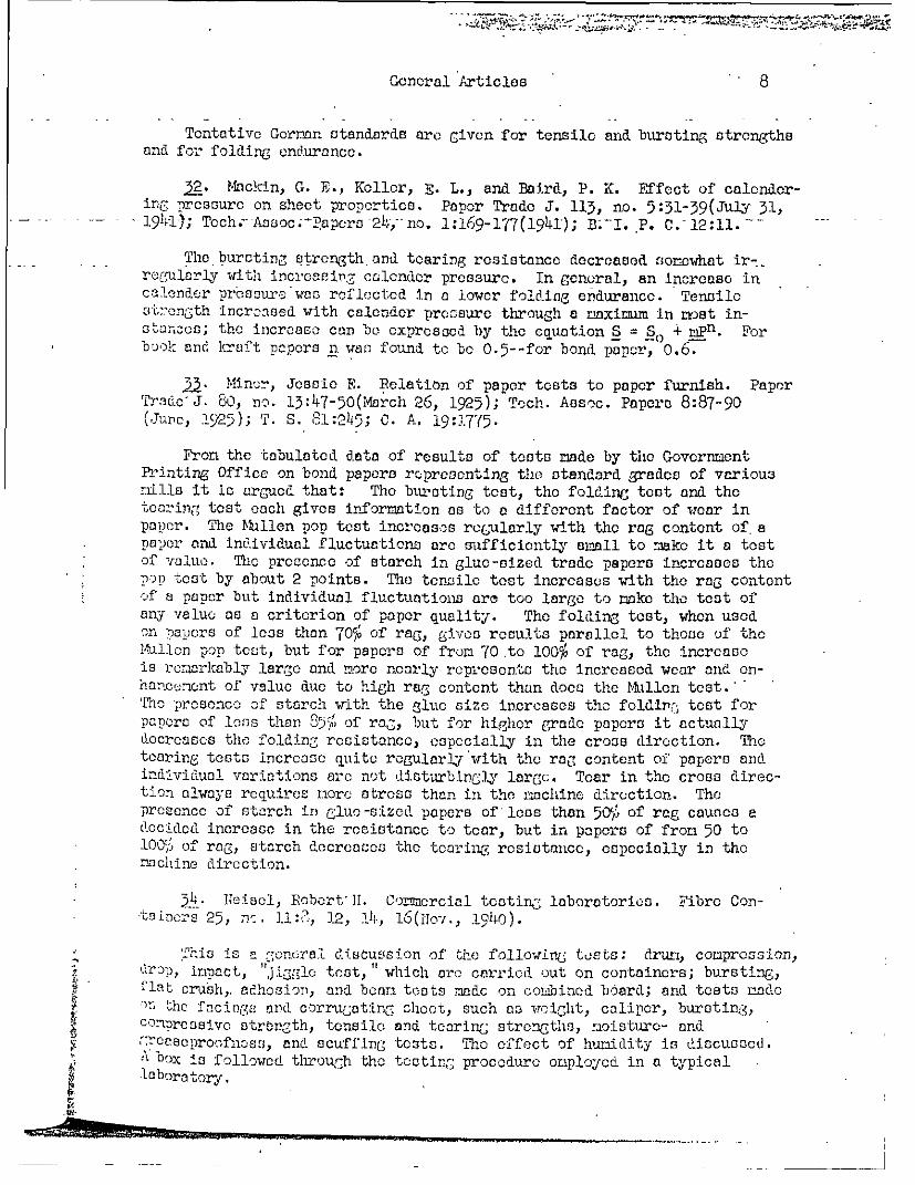
Tentative Gorman standards are Given for tensile and bursting strengthsand for folding endurance.
32. Mackin, G. E., Keller, E. L., and Baird, P. K. Effect of calendar-ing pressure on sheet properties. Paper Trade J. 113, no. 5:31-39(July 31,
..- - -19-1); Tcch.-Asoc.-Papers -24,-no. 1:169-177(1941); B.-I. P. C. 12:11. -
The bursting strength and tearing resistance decreased somewhat ir-_regularly with increasing calender pressure. In general, an increase incalender prossure'was reflected in a lower folding endurance. Tensilestrength increased with calender pressure through a raximnm in most in-stancrs; the increase con be expressed by the equation S = S- + mPn. Forbook and krai't papers n was found to be 0.5--for bond paper, 0.6.
53. Minor, Jcssio E. Relation of paper tests to paper furnish. PaperTrado' J. 60, no. 13:47-50(March 26, 1925); Tech. Assoc. Papers 8:87-90(Junc, 1925); T. S. 1:245; C. A. 19:1775.
Front the tabulated data of results of toots rmde by the GovernmentPrinting Office on bond papers representing the standard grades of variousrills it is argued that: The bursting test, the folding test and thetouring test each gives inforrmaton as to a different factor of wear inpaper. The Mlllen pop test increases regularly with the rag content of apaper and individual fluctuations are sufficiently small to make it a testof value. The presence of starch in glue-sized trade papers increases thep-op tost by about 2 points. The tensile test increases with the rag contentof a paper but individual fluctuations are too large to nako the test ofany value as a criterion of paper quality. The folding test, when usedon palprs of less than 70% of rag, gives results parallel to those of theMulleln pop test, but for papers of from 70 to 100% of rag, the increaseis ror.irkably large and more nearly represents the increased wear and en-hancuneont of value due to high rag content than does the Mtllon test.' 'To presence of starch with the glue size increases the foldir; test forpaper of loss than 85' of rag, but for higher gradc papers it actuallydecreases the folding resistance, especially in the cross direction. Thetearing tests increase quite regularly with the rag content of papers andindividual variations are not di.soturbincgl large. Tear in the cross direc-tion always requires nror stress than in the machine direction. Thepresence of starch in glue-sized papers of loss than 50o of rag causes adecided increase in the resistance to tear, but in papers of front 50 to100,. of rag, starch decreases the toaring resistance, especially in thenachine direction.
-34. Beisel, Robort'Il. Cormnrcial testing laboratories. Fibre Con-taincrs 25, nc. 11:, 12, 14, 16(owtv., 1940).
'nhis is a gcne-ral discussion of tljh followinCg tusts: drunk, compression,riop, iact,iCt "Jiggle teat," which arc carried out on containers; bursting,' lat crush,, aEdhsioT, and bean tests madc on combined board; and tests nado
l the facingE and corrugating sheet, such as weight, caliper, bursting,coenressivo strength, tensile and tearing strengths, moisturo- andrr cascproofnoss, and scuffing tests. The effect of hunidity is discusacd.' ox is followed through the toting procedure onployed in a typicalloboratory.
4r *0,

General Articles 9
).Now box tasting laboratory. World's Paper Trade Rev. 103, no. 20:1542, 15144(may 17, 1935).
A very brief description Is given. of the Box Testing Laboratory atPrincesflRisborough~. Mention is made -of the d~nm test, compreason test,and. drop teot.
3--New QUOC laberatory-for package testing. Modern Packasing 18,noe. 2:92-94, 154,(Oct., 1944).
This laboratory is located, at Ca~mron, Va., andi is known as thePacka.-e Research and flevolonmont Lciboratory. A rather popular descriptionis civen) of the, tes;ts can-icd out by the laboratory.
5J Parms, Paul. StrenGth etn of fibrous shipping containers.Papie'r-Zt[,. 64, no., 52:ll37-1JJ40(JulY- 1, 1939); B. I. P. C. 9:577.
A roviewr is j,4ver. of the nectho(Is emlPloyed, or under develaptent atthe AltenburC laboratory for tasting chipping containers. They ore con-sidered under (i) raw material and. (2) the container itself. The firstGroup of toots includes 'bursting stren.gth,, tearing4- length, elonga0tion,snoothlines, abaorptivity, permecability -to air~ hlgt, oand moisture, free-don front acid, sash content, etc. Because the raw naterial (paper or
lt board) Is subjected to a nunabor .of convertinG operations, such as creasing,-scoring, fluting,, bendinG, posting., stitching, etc., the physical preperticsof the. finished. container vary a Creat deal from those of the base manterial.A nur~er of tests andJ instruments haveo beecn develemedc in Anerica andEurope, the noer important of which are discussed, -including the revolvingdrum and its linitations, corrproesivo strength (resistance to verticalloaLing-), for which the Altenburg laboratory employs a hydraulic proes,the resistance 'to impact fromn the outside,) the resistance to shaking,, etc.
~.Parin, Paul. Te~stirng of raw materials used in the conversionof boards. Pat~icr-Ztg. 67, no. 20:454-455; no. 21:475-476; no. 22:494-1495(Oet. 1-0, 24, Nov. 7, 194i2); B. I. P. C. 14:74; C. A. 33:25-2.
A brief description is .i-i-n of procedures and, apparatus uscd in boarOdtestinG: boar(, scales, mi~crometecrs (caliperj, Bold: smorothnecss tester,bcndinC and folding, testers, bursting otren-th tester (,which also gives an
F, ~indication of the dIrawing- properties of the board), and tearing, strengthtester, which Gives values f~or teer, breaking length, and stretch; bondingstrength of plies, stiffness, absorztivity, ands strength of the score.
2~Possanner, B. von.. Changes in, breaking7 length, stretch, foldCani bursting sti-nmrjthl and in thce dogreec of sizinG upon calendaring ofpoper. Pnpier-FPabr. 25~, i 30:1455-462(July 22, 1928); T. s. 39:267.
Seventeen teosrngn romL nt'.;sp~rint to rag: bond, wero testedin. the; nahn-inseiClLU f n'fter 3, 6, 12, and 18 passes.through Et c.Tdo ith a pressures ti 150 kg.:. pa~cr sq. cim. The results
or,- irtablnr ~=ion- als inCraphs. Pap.aYriless than. 60 gramsp -so.__i wi-i i then crintaining, uuch mechanical pulp showed, but
little increase in. strer;7th withi incre-asing- finish. Thicker papers or

: - -'* -^·-. - :";
7' -* '-. : ::--;v
General Articles 10
those containing less mechanical pulp show 5-6% increase in-breaking -length. Heavy papers or those made of pulp from wood, strew, or ragsshow increases of 9-11%. Stretch generally increased 20-30%, fold30-50% (occasionally 100$ or more). Burst increased 15-35%. A freerstock or one containing more ash gave a smaller increase in strengthvalues. Repeated calendering of a few samples showed that the strengthfinally reached a constant value and did not tend to decrease.
40. -Pretesting containers to lessen damage in transit. Shears 56,no.-551:14-19(Nov., 1938); B. I. P. C. 9:215.
This article gives a rather popular description of the testinglaboratory of the F. J. Kress Box Company, of Pittsburgh. The varioustents are listed; for the most part they are those given by Plaskettin U. S. Dept. Agr. Tech. Bull. No. 171(1930).
41. Quinn, Don. Standards of quality. Fibre Containers 26, no. 8:105(Aug., 1941); B. I. P. C. 12:56.
The following tests are suggested as the basis of quality for corru-gated containers: basis weight of combined boards, caliper of the liners,Mullen or Cady bursting test, strength resisting crushing forces, andstrength of scored edges resisting tear. Other strength properties areimportant for specific articles, but the above are considered fundamental.
42. Rendall, A. G. Paper testing. Proc. Tech. Section, Paper-makersr Assoc. Gt. Britain Ireland 5, part 2:129-142; discussion, 142-145(March, 1925).
A brief discussion is given of the strength tests of paper. Theseshould be carried out at a relative humidity of 65%, which is best obtainedby leaving the cut samples for testing spread out in a desiccator contain-ing an approximately 50% solution of calcium chloride for 6 hours. Theeffect of temperature is so small as to be neglected except under specialcircumstances.
43. Saxl, Erwin J. Physical testing of rayon yarns and staplefiber. In Rayon and staple fiber handbook, 3rd ed., 1939, 501-600.
Itny of the instruments used for the strength testing of paper aredescribed and illustrated.
44. Schniowind, H. Z. The value of tests for paper. Pulp Paper Mag.Carada 28, no. 8:289-291(Aug. 22, 1929); Paper Ind. 11,. no. 3:535, 537(June, 1929); T. S. 90:222; C. A. 23:5584.
A brief discussion is given of the significance of the various strengthtests for paper.
$c 45.. Schopper, Louis. Schoppcr strength testers. Folders No.20803-20805. n. d.
Brief descriptions and illustrations.L*
fl
"IIIA- ,, ,, ,-~~~~~~~~~~~~~~~~~~~0*949

General Articlcs
-4. - Scott Co., Henry L. Combination tester for yarns, twines, cloth, - -paper. Circular BF. 5-28-34.
Illustration and very brief description.
47. Scribncr, B.'W., and Carson, F. T. Paper testing.- ... t..ture of pulp and paper, Vol. 5, Section 5. 3rd ed.- 1939.
In Manufac-
.Tensile strength, stretch, p.-2 4-26; breaking length, p. 26-27; wettensile strength, p. 27-28; bursting strength, p. 28-29; folding endurance,p. 29-30; tearing strength, p. 30-31.
48. Skinkle, John H. Textile testing--physical, chemical and micros-copical. New York, Chcm. Publ. Co., 1940. 272 p.
Chapter 8 (p. 104-140) covers strength and stretch testing of fibers,yarns and fabrics; many instruments used for paper testing are considered.
49. Southwick, C. A., Jr: Testing package materials. PackagingCatalog 1943:23-27; 1944:45-49.
The number and kinds of tests. needed to define a substance are determinedby the complexity or functional properties of the material. Unit testsmust be integrated with the tocts on the package, the composition of theproduct, and the conditions and place of handling and use. Material testsare divided into tests of mensuration, mechanical tests, visual properties,and chemical tests. Package tests, are divided into mechanical and chemical.These tests are not described in detail but their significance is discussed.The author gives the following outline:
MATERIAL TESTS
Monsura-tion
AreaWeight per unit of arcs
of baseof added material
Calipnr or thiclmessSpecific gravity or density
lMchanical
BurstingTensileTeerFoldFlexibilityElongationPorosityPressure and heat blockingMolting rangeScaling strength
Visual
GlossSmoothness
no pressureunder pressure
OpacityTransparencyColor
Chemical
Air and fixed gasesWater
absorptionpenetration
Water vaporOils and greasesOrganic vaporResistance to special agents
War gasessolventsAcids, alkalics, and chemicals
S ability-effect of light, heat, and agedimensions and weight
Flanmability
2
Ly.
�BF�da�B52E�S�nn�
11

I .- ,- ....-.
General Articles 12
PACKAGE TESTS
Mechanical
Mechanical- --Tumbling and drop
Chemical
Grease penetration Flavor lossWater
- - . - -War gases - - -Oxygen and other fixed gases
Moisture migration
50. Sutermeister, Edwin. Chemistry of pulp and paper making.3rd ed. New York, Wiley, 1941. 529 p.
Physical testing of paper is discussed on pages 4!47 to 465.
51. Sutermeister, E. Paper and wood pulp testing. In Allen,Commercial organic analysis, 5th ed., Vol. I:593-637(1925).
72. Wehmhoff, B. L., and Kantrowitz, M. S. Study of methods ofevaluation of kraft paper. U. S. Govt. Print. Off., Tech. Bull. 12,1931. 17 p.
The data tend to show that the folding endurance test is the mostindicative of the quality of kraft paper. There appears to be no exact re-lationship between the folding endurance and any of the other physical testsstudied. Although the test requires considerable time, its use is advisablesince no tests have as yet been developed which will yield as definite in-formation regarding the quality of the paper. A combination of foldingendurance and tensile strength tests was investigated and found to give re-sults at variance with those obtained by either test alone. It is doubtfulif the combined tests would furnish information of value in indicatingthe quality of kraft paper. The bursting strength test alone had previouslybeen found unsatisfactory for this purpose. However, its use in connectionwith folding endurance is probably advisable, particularly in view of thefact that it serves as a quick control test in the paper mill. Tensilestrength test results, while yielding some information, wore practicallyall found to be within such close limits as to make comparison betweensamples difficult. As a rule, those samples showing high folding enduranceand bursting strength also had high tensile strength. Thickness, stretch,and porosity are apparently of no particular value in evaluating kraft paper.
Z.. Wells, Sidney D. The effect of the adhesive used in the fabrica-tion of corrugated fiberboard on the strength and serviceability of corru-gated fiber boxes. Fiber Containers 24, no. 10:3, 12, 14, 16; no. 11:8,12, 14(0ct., Nov., 1939); B. I. P. C. 10:113. Reprinted, with an appendixcontaining testing data, by the Institute of Paper Chomiistry, 1940. 105 p-
Brief details are given of the compression test, i4tllcr test, adhesiontoot, flat crush test, column test, beam teat, and small revolving drum test.
i'I1!
ii.i"i4.
i
it,
s^I
i

.I -i- -L.-t.4- -1 .. a , l-
15
EFFECT OF HUMIDITY IN PHYSICAL TESTING
58.Additional references on the effect of humidity will be found in No.
'5.4. Campbcll, Rose. The effect of humidity on the moisture content-of paper. -Paper Trade-J. -73, no. 2:30, 32, 54(July 14, 1921).---
The results of laboratory experiments have proved conclusively thatthe moisture content of paper is independent of the furnish and kind ofpaper, is a function of the relative humidity of the air in which the paperis in contact, and is independent of the method of test.
52. Campbell, Ross. Physical testing of paper as affected byhumidity. J. Ind. Eng. Chem. 9, no. 7:658-661(July, 1917); J. Soc. Chem.Ind. 56:925; C. A. 11:2543.
The physical tests on a large number of papers of various grades wereconducted under varying conditions of humidity. Most of the results de-creased 40-50p as the relative humidity increased from 50 to 98%. Stretchin the machine direction increased about 530 ard in the cross direction about40-50% under the samo conditions. In all but two cases, the folding testresults tended to reach a maximum at about 80% relative humidity.
56. Carson, F. T. An analysis of the strength of paper. Tech. Assoc.Papers 7:73-78(June, 1924); Paper Trade J. 78, no. 12:51-56(March 20, 1924);Paper Makers' Mo. J. 62, no. 4:154-155, 164-165; no. 5:191-194; no. 6:245-247(April-June, 1924); World's Paper Trade Rev. 82, no. 10:746, 748, 750;no. 11:854, 856; no. 13:1016, 1018; no. 14:1100, 1102(Scpt. 5-Oct. 3, 1924);T. S. 79:66; C. A. 18:1570.
i?:' Thiz is largely a theoroticnl discussion of the effect of humidity
|I' on stretch, foldirf onndurancc, and tearing resistance, and only a few dataarc givcn. The 3trongtl. of' paenr is attributed to the net effect of twoindcpcndcdnt factorLu, tho str-cnth ard. flexibility of individual fibersand the rntual adhorore: c of the fibers. The papcrmaking fibers arc comparablein strength te tho conron t rot.as and alloyu. Emphasis is i laced on thesurface friction of fib-rs. The capillary theory of adsorption is employedto explain the behavior of thr vegetable iiberc with changing humidity.Thc effect of the surface tension of the adsorbed water and the tensilestrength of confined liquids are offcreld o an explanation of the increasein strength of the cellulose fiber with increase of relative humidity.Dcrease in fiber friction resulting from tho effect of adsorbed moistureis considered responsible for the decroaso uith rising humidity of tensileand bursting atrcngth. Increase of folding endurance is explained by theincreasing flexibility of the fibers with gin in moisture content. Thebehavior of tearing resistance is explained by the influence of the moisturefilm on the surface of the fibers, tending to resist the "peeling" of fibersawy fror 3ne another, the predominant feature of tho shearing tear. Itis Pointed out that tensile strength and stretch are increased by increasingthe rate of loading and the anomalies observed by Houston are explained onthis ground. The relation of' bursting pressure to stretch and tensilestrength is shown by the equation P = 2T/R, and it is pointed out that the
½

Effect of Humidity in Physical Testing 14
increase in the bursting value observed on speeding up the Mullen testeris due to the concomitant increase of T and decrease of R. P is thebursting pressure, T the tensile breaking strength per unit width andR is the stretch.
- ..----- 57--Houston; 'Paul-L., Carson, Frederick T.;' anirl Kirlkood, R; S.Effect of atmospheric humidity in the physical testing of paper. PaperTrade J. 76, no. 15:237, 239, 241, 243, 245, 247, 249, 251(April 12,1925); Tech. Assoc. Papers 6:64-71(1923); T. S. 77:1; C. A. 17:2501.
The results of an extended investigation by the Bureau of Standardsinto the effect of humidity changes on the physical properties of paperare presented. Data and extracts from the literature are cited to indicatethat the physical qualities are determined by relative humidity ratherthan by absolute humidity. The data are presented as graphs of the per-centage variations from values at 65% relative humidity, because thiscondition is used almost universally in the industries. Eleven grades ofpaper were tested for nine physical properties at eight relative humidi-ties from 15 to 835. A description of the method of procedure for eachtest is given and is accompanied by a discussion of results. The paperstested included printing, writing, bond, lodger, bristol, and wrapping.The data are given in tabular form and also in curves. Breaking Strengthunder Tensile Stress. In practically every case the curves show an in-crease up to 35 or 4% relative humidity, after which the breaking strengthdecreases with increase of relative humidity. In general the relativeeffect of humidity changes is the same in machine and cross directionsfor the same paper. Folding Endurance. A Schopper machine was used.The folding endurance curves show an increase throughout the range tested.In some cases the rate of increase begen to fall toward the end of thecurve. Tearing Resistance. The Elmendorf tester was used. The prodominat-
; ing curve is of a sinuous conformation following the moisture content curvein its mid-portion with departures at either extremity. In nearly allcases the rate of change has begun to decrease and in a few cases themaxiunim tearirn resistance appears to have been reached at 853 relativehumidity. Bursting, Stregth. Using a Millon tester, the curves arc similarin type to those of breaking strength, but the varintions with relativehumidity are not as great. Of the strength qualities considered, burstingstrength is leant affected by humidity changes, breaking strength and
0t tearing resistance eosumo an intermediate position and folding enduranceis affected most.
.58. Institute of Paper Chemistry. Instrumentation studies. XI.Effect of humidity in the physical testing of paper: a survey of theliterature. Paper'Trado J. 104, no. 14:40-46(April 8, 1937).
A bibliography of 97 references, with brief abstracts of most of thearticlcc.
2%. Institute of Paper Chemistry. Instrumentation Studies. XII.Effect of relative humidity on physical properties with respect to thehystaresis effect in changes from one humidity to another. Paper Trade J.104, no. 15:45-48(April 15, 1937); T. S. 106:50.
i ·- -·llar*�l�er;·luarru*;c.u·l·r�-nc -··-- -- -Il·uLa�-�c·-·--- ·I--·411-·-·lr.u- i -

Effect of Humidity in Physical Testing 15
Values are given for bursting, tensile, and tearing strengths andfor expansion for 18 samples of papers of various kinds in which therelative humidity at 70° F. was raised from 40 to 75% and then returnedto-:0o'-(4o, 50,-65, 75, 6 5,-50, 40).--The- hysteresis effect in moisture --contents accompanying changes in relative humidity of the atmospheresurrounding samples causes a hysteresis in those properties which areaffected by moisture content. The magnitude of the effect is largee-ough to have an important bearing on the accuracy of test results.Where accuracy in testing is required, all samples should first beseasoned for at least two hours at 35% relative humidity before beingexposed to the standard conditions for testing.
60. Jarrell, T. D. Effect of atmospheric humidity on the moisture|' ,content of paper. Paper Trade J. 85, no. 3:47-51(July 21, 1927); C. A.
21:4067.
;' The amount of water absorbed and lost by 50 samples of common papersof different grades exposed successively in air of 35, 50, 65, o8, 65,
. .' 50, 35, 50, 55, 80, 65, 50, 35, 65, and 35 degrees relative humidity at700 F. was determined. The results show that the water content of thepaper is appreciabl. higher at 50 and 65% than when approached from alow humidity (35',). Some samples of paper of the same class show a widedifference in water content. Paper containing groundwood, rope orsulphate pulp contains more water at a given humidity than paper madeof all rag, coniferous wood (sulphite), broad leaf wood, or a mixtureof these. Newsprint has a higher and blotting paper a lower water con-
~-. | tent than any of the other classes of paper tested. Experiments on therate of absorption end loss of water when paper is transferred from anatmosphere of 35% relative humidity to one of 65% at 70° F., and thenback to 35% humidity show that water is absorbed more rapidly than it islost. In general, under the conditions of the experiments, 48 hoursare required for the atteiimeint of equilibrium when the paper is trans-rcrrcd from 35 to 65% relative humidity, and about 6 days when it ischanged from 65 to 35% hauidity.
1. Kioly, Eelcn U. Comparison of paper tests made at various:L reative humidities. Paper Trade J. 80, no. 6:207, 209, 211, 215(Feb. 5, 1925); Tech. 'ssoc. Papers 8:54-57(June, 1925); T. S. 81:80;C. A. 19:1775.
uIllen Teot. The Mullen test changes but slightly with increasein relative humidity from 50 to 65%, tending to increase very slightlywith decreased humidity. Tensile Test. The tensile test shows a generalincrease of about 15% on all grades of paper on decreasing the relativehumidity from 65 to 50,. The machine tear shows an increase in the caseof bonds and ldcors of about 8% and a decrease in the case of books,Covers and writings of about 10%. Folding Test. The folding test shows a de-crease varying from 0 to 50%; most of the figures fell within the range of20 to 30% on the cross direction fold.

$4
IDC
) 0I
4P,
..
0 00
PC
.3-4~~~~~-
4'I
PC))
o ~~~
0
r0
02
4-) o
~~t-CO
-ft-
-P~
~~
~~
~~
~-
o .~
~~
o
0 0H
J
'2C$4
&
~ C
) P
I 5
-4 0
NIC
.0
Ž
0) 2
co S.
4'O C
O
H
0O
'r 4
$4 '
o-'4-i g$4t 4'c
,ElP,
00
)
cId
O0 H
M$
$
C'
1H
0' C
) C
a
A0'c
0P, P4- Q
) M
P,
fl.PC
H
a) (a0030:
Q
4,O
P3
=00
tCV
H4C
000co
C
4 ,
Id 44P$404
C6 $8
4
10 1-0
P.0
03
Ho
mg
Cis
o
$4
'd4
-'
0Id-P
3
.PI~
A
t)-PP, -Pr
t~ L4
C
CO
O
f $4 P
.)PQ
0-P.
Pd
QP
:5R
0C
3
OX
.H,0
v C
,0.t -P
Iti-.-P
C)0
O
-fW
-
oP ocici-o
C!-PC
) '-0U
430o
$4C0
0Wr1 4
4-C) C
)$4 'tP
-
S03
-PC
-P04PIO
4cID
CoC
,Ž
"Id C)
INPd
,oH
co Id
.0a~~~r\ ,d3co4
h
4iC)
1-f
4-j P
,
co~C)-A
H
irN
C3
rn-P
C~
C
cri 03.C
O
co
.- 04
tflC\
'H 3
0.
2 r3
-) P.0-
C
cM
Io
t-r-4
C.)
4'-
00-i O
C
H
0-PI
) 4
,C'
M$4
$4D
0
30
0)
40 C
)
$4 4
40P
0IC
0 o
oC
$44P
I C
t
t- 4r-
00I
$ P
I C
)0
ED
H
4Ž
r-0P
4-400004-PX
-Ps
04
C
C
o -H
OH
S-4
d
ci -Pci
$
C)
a 0
4C)
C3C
0 E
D3
4-)P
44
o 0
0 1-
C)C
C
03 C
O
ro A
- 4:. -. 'rI
'i0
CJ4
4H~
030 4' § 4-)
C)
P"I
$4
C-H
r-4
0PqQ
Nc ci-
'-4
4-N
0-'
PI
C
CjId00
4~C)
4-
~LI
1aCCPI
E)c
i
IHH~
C)
03~~
~~
cH
t~~~42'r4
04''Z
i 4
)4 C
H
4i4
PI ciC
ci
4-.4
'A
H
0204
H
'-'6 0
0-
''c PAIdH
P.4Ž
H
34' U
i i
i -
13 H
C
C
aC)
Pio s5
tC)
CH0 tlop~c4-'
rA .c
C4 4H
0~
002
r4~4
0a~a)nIC
ID H
, P
$4
Hw
K 2
"S-o
"00w
44 4
-~
~w
~~
I-~~
AcA
~~
-v 4'
'3
1 .- ;
__
-
i
4
I
I

$4"
0~0C.)*
ro r-
02
H
~ ~~C
) C
kci~
~~
P
02
o s- -i000
0$
-
C)
r
0 0 w
a)d
"
4i P
1-4 4
H0
02104
$1000)
4-'G
P
I
-4frI 20
.C'
4O --
Ia U
'n4H
0
024
$4$-
PI
'H
-P
al 0
CUcM
S-4 4
C30
2
o P-
$0C)
IqC)
$4 0-P
.?
00
4:
C3
$4 -p.-I0
V
,- 02
H-P
Id£4
O: ,4
41O
-P
4'r
04$-40 -P
~~
~~
4~0
Id0C.)
4j, +
) to
'O
'--cr-A
W
O
P4H
P
.~~ $P.4
' C
O
0 4~~a
-'0O
dO
'd
(2~~
C30
'HA
Gf
~~H$4 .~
~Z
iC) 4
-P4$
4 ;4'
OH
) 0
Cv'tA.4~-P
-P 4)
q-.H
~~44-P-- ,-4
0-4
m2
20-rl£
£1
$
'04
-'t~
C)
14 021.4cO
0 ,0
o
P4 02t
) i
0C
CO
IOE
-4P
.
C0 r1
$4O
O
C3
o
00E0P
C
$4C
(fl4 4-)
$4CO
4)0
ZTN
d0.0Cr40
02
4~ ~4 4
r tD
di
00'40 X
:)HP4
-'r44 ..
3 0
P C
to r4,Q
.0
C
r4 0
n-i
'H
tCL
ri
$4
0-C
4a 0
d
i4-' m
+'O
£1A
~~
~O
'C)
*: n
c)
C)
~ ~
~ £
HC
;4- $4P
0-
4- O
tI S-- P
.~
C
$4CO
C) 4
CdOO
4
0 -P
£154
ON
otn
,-O
. H
.0-0293-tPi
C)
8-)
tD-IdciC-:.
$4
to0
-Jrl:5
,0ci40
Ho
, IdU)
.5:5
"-
a)0
4-)0
0I-) r
l.00
-4-:5
1to
v-I IP"-
0V
sI -H
- -P02C.0
C3- '-f
-20
-7

18
AIR PERMEABILITY (POROSITY)
67. Abrams, Allen, and Chileon, Warren A. Vapor transmission through--papers. -aper per ade J. 91,--no. 18:175-180(0ct. 30,1.930); Paper Mill 53, .
no. 53:24-28(S5ot. 20,-1930); Tech. Assoc. Papers 14 :379-384(May, 1931);Paper Ind. 12, no. 6:1047(Sept., 1930); C. A. 24:6011; T. S. 92:159.
No data on porosity are given, but the statement is made thatporosity bears no direct relation to the water-vapor transmission throughthe sheet.
68. Ainalie, R. A. Uses and limitations of some paper-testing in-struments. Proc. Tech. Section, Paper Makers' Assoc. Gt. Britain Ireland17, part 2:475-488; discussion, 488-492(March, 1937); World's Paper TradeRev. 107, no. 18:TS8-12; no. 21:TS28-32(April 30, May 21, 1937); Paper-Maker 93, no. 2:TS26-31(Feb., 1937); B. I. P. C. 7:276; C. A. 31:6876;T. S. 106:93; B. C. A. 1937B:228.
-- , 'The discussion is confined to the Gurley densometer. The personalerror is small, provided the instrument is leveled and the clamping nutsare screwed down reasonably tight. The instrument should be used withparaffin oil or similar liquid and not with water; dibutyl phthalato isvery useful. The time required for a test varies from a few seconds upto half an hour for most types of paper, though in the case of glassinesand greaseproof papers, the time is impracticably long. The most seriouserror can arise- from the difficulty of. clamping the specimen down to makean airtight Joint. In exact laboratory tests, a thin film of vaselineshould be used as a seal. By using a soft rubber washer, made from anold Schopper bursting tester diaphragm, observed variations greater than
-1 2% traceable to air leakage were not found. Experimental results show theconstancy of repeated tests on a single specimen (for 20 tests, the averagedeviation was 0.57 second and the maximum deviation was 1.45 seconds),the effect of liquid (comparison of paraffin oil and dibutyl phthalate),the effect of cylinder immersion depth, and the method of sealing.
6.'- Air permcability of paper. J. Franklin Inst. 215, no. 6:747-74 8(Juno, 1933).
A brief report from the National Bureau of Standards states that thechief source of uncertainty in the available air permeability testingdevices is in the leakage in the apparatus or at the edges of the spoci-Mcn and the absence of simple moans for detecting such leakage. Instanceswere found in which the error from leakage was as groat as the air por-meability itself. Other doficioncics noted wore: small testing area,Inconstancy of driving pressure, lack of sensitivity, and length of timerequired to test papers of low permeability. This work is apparentlypreliminary to the development of the Carson tester.
9 0. Air permeability of paper. Wochbl. Papierfabr. 64, no. 10:174,(March 11, 1933).
i'."!]-,

.ir Permeability (Porosity) 19
Using the Dalen tester, experiments were conducted with a pressure of1, 2.5, 5, and 10 cc. of water on four samples of paper. There was no rela-tionship between the air permeability and the pressure. The values for thepermeability fall during the first few minutes of the test (e.g., for onepaper the values fell from-532 to 502-in 8 minutes); after 10 minutes, the- values become steady.
71. American Society for Testing Materials. Tentative Methods ofsampling and testing untreated paper used in electrical insulation.A.S.T.M. Designation: D 202--41 T. A.S.T.M. Standards 1942, Part III:1187-1206; A.S.T.M. Standards on electrical insulating materials, Dec.,1941:546-365.
The determination of the air resistance of paper is included in thismethod. [See also Croincr, No. 96.]
72. American Society for Testing Materials. Tentative method ofteot for resistance of paper to passage of air. A.S.T.M. DesignationD 725 - 43 T. A.S.T.M. Standards, 1944, part III:1346-1348; A.S.T.M.Standards on paper and paper products; Nov., 1945:127-129.
- * This is similar to TAPPI Standard. T 460.
3-. American Society for Tosting Materials. Paper and paporboard--characteristics, nomenclature, and significance of tests. Philadelphia,The Society, 1944.
l Porosit06 . This toot is used for control purposes by many paper mills.Some believe that the oil absorptivity of paper is controlled by porosity,while others use the test for indicating the degree of compactness of certainpapers. Porosity is a fnctor in the quality of printing papers. For example,
n the offset process, porosity controls to some extent the spreading ofthe ink under the pressure of the rubber blanket. In:printing illustra-tions by the offsic-a process, the porosity, osp;cinlly that of the surfaceof the paper, is of particular importance. This test is also used to aconsiderable extent to control properties other than those relating toprinting characteristics, such as (a) the filtering characteristics ofindustrial filter papers, and (b) the saturating properties of impregnat-ing papers. Porosity tests are also of value in determining the charactoris-tics of bag and insulating papers. In paper bags which arc to be filledwith a heavy material it is essential that the air porosity of the paperbe controlled so that the air can get out through the paper during fillingfrom automatic filling machines, otherwise the bags will burst.
74. Andlorson, L. C. R.-sulto on noewprint obtained by use of theBe0lk smoothness and -porooLtyi tostCr. Pulp Paper Canada 55, no. 2:85-86(Feb., 1934); 2. A. A23:201; T. S. 99:118.
A study of the instrument no used for the testing of standard news-Print (33-pound basis weight) showed that the time factor for convertingresults by the "rapid" method to those by the "precise" method is about10 9; that the time with the "rapid" method must road to 0.1 second to ob-tain the same accuracy as the "procisc" method; and that there is a ratherlarge probable error in testing newsprint because of a lack of uniformity,

Air Permeability (Porosity) 20
so that at least 10 (and preferably 20) tests should be made to obtain agood average value.
75. Aono, Takco. Permeability of gases and vapors through packingpaper and a simple measuring apparatus. J. Soc. Chom. Ind., Japan 35:443-444B(Oct.,--1932); T. S. 97:131;-C. A. 27:1-165; B.-C. A.- 1933B:57.
The apparatus consists of two hollow hemispheres between which thetest shoot i-theld. The upper hemisphere (volumcAA) i s connr ctod to a
mercury nanometer and a gas inlet tube through two three-way cocks; thelower one (volume B) is connected to a small sphere (volume C) and tothe gas inlet tube through a tlree-way cock. To determine the perTeabili-ty of paper, the whole apparatus is evacuated to a pressure of P, thesphere is filled with the desired gas to a pressure P', and this is ex-panded into chamber B. The volume (V) of gas which passes through thesheet of unit area in unit time with a pressure difference of 1 mm. ofmercury is given by the equation V = ka/760S, where S is the area of the
test sheet and k is (PA - P)/P't.
|j; 76. Arnold, Lionel K. Air infiltration through insulation board.Paper Trade J. 105, no. 4:40-42(July 22, 1937); B. I. P. C. 7:407; T. S.106:94; C. A. 31:8189; B. C. A. 1937B:1037.
This may be considered as a study of air permeability or porosity ofinsulation board. The apparatus consisted of two sheet-iron boxes open onone side; a flange was placed around the open side so that they might bebolted together; one box had an air inlet and the other an outlet to agasometer; both were eqolipped with manometers. In testing, the board wasclamped between the two boxes and air was led into the first box untilthe desired pressure difference was built up; the air was allowed to pass
p? through the board at this constant pressure drop until the naximum dis-
placotcnt in the gas hol.er had been reached. The velocity in terms of
cubic feet per square foot per minute was then calculated. The influencejj' of various board properties was studied. [See also No. 132.]
f77.' Barr, Guy. Moasuremont of the porosity of textiles. J. TextileInst. 23, no. 8:P206-212(Aug., 1932).
It is pointed out that the pressure difference causing the flow ofair through textiles in a porosity test should be specified if agreementis desired between tests on the sane material, and that the pressureshould usually be small (less than 1 cm. of water). Tho area of thetest piece may affect the result in view either of edge effects or ofthe tensions resulting from the application of pressure. A method ofclamping is suggested which allows leakage at the joint to be detectedand rendered negligible, and a gasometer type of apparatus is proposedfor routine tests to avoid the inconveniences of the methods heretoforeUSed. A proposed apparatus is described, and the method of measurementis given.
78. Bokk, Julius. Horizontal porosity with the Bekl: smoothnesstester as it affects smoothness. Paper Trade J. 99, no. 18:31-33(Nov. 1,1934); Papicr-Fabr. 33, no. 4:30-32(Jan. 27, 1935); C. A. 29:540, 6053;B- C. A. 1935B:17, 222; T. S. 101:131; 102:10; B. I. P. C. 5:101.
�rm�arr�llg*tlgll�p[�I�DaW1�^4P"-�;�·Y�-

N-
00 I
ci 0-H
P.
O
-40~4
3 0 1
0 4-4
4,
> 3
f r040
H
0
O
.1">
C
) M
C
)
10o
-P0
p -.4 3
0 m
4>1
0P
"-c-aCC
) )
-
"co
43 0
0 04-,
o ' 04
c 0
C )
0 i i
43
C.-. 0
dH
~
0
H 14
03 4-
C
.4
34
3o
Oto
Aco
42 0
4-) 00 >
~
400
r 4 L -P '
J wo
* 4
I- -3
'i C
) t
flY4 O
H
-r0 0 .
P I 0
Di
4dC)I
C'
p-coiC
)
03+-3
00.02
Id0IV43H$40.0`-P
C4
.3A)
CZ
-1H003PI$4
0.0-c90o A
,004-
H
4' P
100
`-P003:0.0
03co
-
-P0
.Id
toW
KD
i o'
$-.H -.
~ P-.i
.P 01 4 4
iO
-C
D
C M
0
P t
fl Q
IC
-,
0 3
co C H L
f N'\
(S
'd H
: C
~\Z) ci
0
r-f I
*~
03 H
co
I
C
03
a) k>
- 0
C
0. N\
C)-I ~
el
-
,-.~,x
'n-t
at
04r:S
C
C
\ H
'0 t-
~~n ~c0
OHu
S2O
~~
M'\ g----
cifl
-SD
OO
C\..Ž
.I--
I* _
Lfl -Z
t 0-
$1 cQ
itnCM
4->
$4 r-'.5
In03' 031444
Z 0
0)
to (L
2
(
4- I- P
I C
) *
0 0
c
C0 0 2
O H
C
+~
0C
)
od co 03
Id 4
0002 4) 0+
0444
,00040
4- 0
-PC
) C
CO
002 I
IC
0 02
43)-))
C
c-I
4-3
~~4g
P-4
C3
(AI'~
14 0"l
P
CQ
02
) C)
HX
HI-
o -b
C-)
C3
044
'-C
04-
C
C)
C3
,000
i
0C
.
4 0
.0O404
PI
03*00
iP4P
03C)
co0'
.02
-I
D.3n14HciCC42CICaC
t 0
C,
P0
00C
) o
0 -H
00
C) q.03404
C-HI
C)
m-
I(a
-C
.StCC:
ICC4ZCs
.02 *03 C
)
40
0'
'00
'H4)
.0C))
$~4 -A00
.-'
>'C
)
0.4
As
.000I4
I,4v-i$4
"-H
00002
1 03 .- 'i
It
004
C3 C
)*-4 H
02
Cd H
0 C
~~~ 0~
~ ~ 0S
iC
C)
1 4-
$00
O
0 0
4-,Id ~ mC
4-i0
:
2 0 0 i
q- 4
-
.3.
:3Id
n0H303
PIE
'02C
)
4-40Ji
Ca -H
-14o H4-4C
)
C3
' )
040$443c- 4030
$4
00-
03
---.-.
I..-.-~ ~ ~~~
'-a
II
I
i

Air-Permeability (Porosity) 22
the sheet surface, the flow through the sheet being about 14% of thetotal flow (for newsprint); the sealing of one side appears to producea false reduction in the finish of the other surface.
81. Carson, Frederick T. Effect of experimental conditions on themeasurement of air permeability of paper. Bur. Standards J. Research12, no. 5:587-608(May, -1934)(RP 682); Paper-Trade J. 99, no. 11:25-34'(Sept. 13, 1934); B. C. A. 1934B:713; B. I. P. C. 4:245; -T. S. 100:119.
Using the apparatus previously described, the effect on the rate offlow of air through paper of' pressure difforonce, time, area, temperature,relative humidity, and thickness of the sheet was studied and the resultsapplied to a discussion of the nature of the air passage in paper. Thefollowing definition is given: The air permeability is measured by the
.. :volume of standard air which passes in unit time through a unit area ofthe material when urged by a unit pressure difference (not exceedingabout' 10 rams per square centimeter) between the surfaces of the sheet.Standard air, for thu purpose of this test, is defined as air at 21° C.,at 65% relative humidity, and at a pressure of 1 standard atmosphere.In a given locality, relative air permeability values may be obtainedwithout cognizance of the absolute pressure. The apparatus should be sodesigned that conditioned air is caused to flow through the specimen,and it should measure all the air which comes through the area designatedas the test area and no air from other sources. This requirement means aneffective prevention of leakage across the clamping surfaces and throughthe cdges of the specimen. The unit for air permeability expresses thevolume in cubic centimeters, the time in seconds, the area of material insquare motors, and the pressure difference in grams per square centimeter(the name norm has been suggested for the fundamental egs unit for thepormeability to gases of all porous sheet materials).
L, a82. Carson, Frederick T. A sensitive instrument for measuringthe air permeability of paper and other sheet materials. Bur. StandardsJ. Research 12, no. 5:567-585(May, 1934)(RP 681); Paper Trade J. 99,no. 16 :44-52(0ct. 18, 1934); B. C. A. 1934B:713; T. S. 101:131; B. I. P. C.4:246.
The new instrument contains a permeability cell of novel design, inwhich an annular cell surrounds the inner testing cell (the original shouldbe consulted for the description and illustration of this apparatus, whichcannot be described without illustrations). By means of this arrangement,the usual error from edge leakage is eliminated through the by-passingof the leakage air around the measuring apparatus. The pressures are soadjusted that there is no latcrni pressure gradient at the boundaryof the teot cell, and hence no leakage into it. A special pressure rogula-tor has been designed to maintain a very steady pressure drop across thenlStrument. The air flow is measured by means of a capillary flow metor,
containing four carefully calibrated capillary tubes. The accurate rangeof the instrument is more than ten thousandfold, and approximate mcasurc-
. ntea can be made over a millionfold range of air permeability values.As the timo oloment is taken care of in the calibration, tests of relatively
t srmoablc papers are almost oa rapid as those of the more porous variety.
W~

I -. -. - .6·iswu;~6~Yr- -t~t~~-,-t -3 tr".r~ .1 . - -J..s
Air-Permeability (Porosity) 23
Results are reproducible on an identical area to within a few tenths of-. -1%. The instrument is well adapted to the testing of leather and some
other sheet materials. It will accommodate sheets not thicker than 0.5inch, and it is not necessary to cut the material in order to test it.31 references are given.
8G. Carson, Frederick T. Some observations on determining the sizeof pores in paper. J. Research Natl. Bur. Standards 24, no. 4:435-442(April, 1940)(RP' 1292); B. I. P. C. 10:392; C. A. 34:7107.
The various methods which have been used to determine the size ofpores in paper arc briefly reviewed. These are of three general types:methods based on the rate of efflux of fluids; methods based on the rateof rise of liquids in vertical strips; and methods based on the capillarypressure involved in penetration by liquids. A new method is outlined,which takes advantage of the fact that the coefficient of slip of air inviscous flow through paper is a function of pressure. From the Moyerequation, the average effective pore radius is evaluated in terms of theair permeability values at two pressures. It is only necessary to determinethe air permeability of an identical area of paper at two differentpressures. Experimental values for two such air-permeability determina-tions on each of five papers, and the resulting values calculated for theaverage effective pore radius, arc tabulated.
84. Carson, Frederick T., and Worthington, F. Vernon. Evaluatingthe wearing quality of currency paper. J. Research Natl. Bur. Standards
' 26, no. 6:467-48S(Junc, 1941)(IP 1390); B. I. P. C. 11:417; C. A. 35:6108; B. C. P. A. 1941B, II:427; Papermaking'Abstr. 1:196.
A description is given of a modification of Carson's air-permeabilityapparatus, which is suitable for testing a 10--sq. cm. area of paper.
85. Carson, Frederick T., and Worthington; F. Vernon. A study ofsheathing papers. Bur. Standards J. Research 3, no. l:75-89(July, 1929)i 85).
Air permeability was measured in an apparatus consisting of a per-meability call, a water manometer, a gas meter, and a rotary vacuum pump.The cell accommodates a fairly large area of paper. The cell consistsof a steel plate having a circular depression (7 inches in diameter and0.25 inch deep), covered by a very coarse wire screen to support the paper.The paper is clamped over the cell chamber by moans of a ring, whichregisters with the annular surface of the cell proper. The vacuum pumpis connected to the gas meter which, in turn, is connected to the per-=ability cell. Conditioned air at 70° F. and 65% relative humidity isdrawn through the paper and the gas meter by the vacuum pump.
86. Colditz, Walter. The degree of porosity of paper. Wochbl.Papicrfabr. 44, no. 5:376-378(Feb. 1, 1913); Pulp Paper Mag. Canada 11,lno ll:401(Juno 1, 19137; World's Paper Trade Rev. 59, no. 13:580(March 28, 1913); Paper 11, no. 3:27(April 2, 1913); J. Soc. Chem. Ind.32:191; C. A. 7:2305.
. ,
22iL
1
·· i

Air-Pcrmcability (Porosity)
The degree of porosity of paper may be expressed as the ratio of theapparent to the real density. The apparent density is calculated by de-termining the weight of a siown. volume of paper.. Real density is de-termined by ascertaining the amount of pure olive oil displaced by a knownweight of the paper.
87. The densomteur. Papor Mill 47, no. 18:18(May 5, 1923); T. S.77:1.
This is a brief description of the early form of the Gurley donsomotcr;its applications to the paper industry arc indicated.
8; 8. Donsomotcr test for textiles. Molliand 2, no. 4:581-582(July,: !: . 1930).
The Gurley donsometer, which has boon used. by the paper industry forsome years, is now being applied to textiles, a new model having beendesigned for this purposo.
b '9. Doughty, R. H. The relation of sheet properties and fiberproperties in paper. III. The effect of fiber length on sheet properties:preliminary experiments. Paper Tradc J. 94, no. 9:29-34(March 3, 1932);Tech. Assoc. Papers 15:137-142(Juno, 1932); C. A. 26:3108; T. S. 95:75;B. C. A. 1932B:713.
Curves are given showing the effect of long and short fibers on theporosity of handshcoct. Although the fiber dimensions are of little im-portance in the strength of sheets made up to constant solid fraction,they have a considerable effect on porosity. The difference is lessmarked than at constant pressure on the wet sheet; nevertheless, shootsof the sarm solid fraction show from 10 to 100 times greater porositywhen made from long-fiberod than when made from ohort-fiberod pulp. Theporosity values indicate that some factors in shoot structure, at con-stant 'solid fraction, vary largely with fiber length; although thisvariation is not indicated especially by the tensile test, it mightshow up strongly in other tests.
90. Doughty, R. H., Scborg, C. 0., and Baird, P. K. The volumetriccomposition of paper. IV. Composition of the air fraction; improvedapparatus and method for determining porosity. Paper Trade J. 94, no.24:31-33(June 16, 1932); Tech. Assoc. Papers 15:2G7-289(Juno, 1932); C. A.26:4715; T. S. 95:222; B. C. A. 1932B:767; B. I. P. C. 2:307.
The apparatus was built from an old hand-operated Mullcn tester.The cylinder of the tester was filled with lead, through which a 0.25-Inch air passage was drilled, thus reducing the volume of dead space inthe apparatus. This was connected with a balancing tank to insure thata reasonably constant pressure drop would be maintained in the systemby the vacuum pump and with two water manometers. The Mullon orificehad an area of 7.55 sq. cm. The connections were of small-bore coppertubing; the size of the tube should be such that the pressure drop ratiobt,:: oon the tube and the sheet will be loss than unity (purely as a
c:... ,
rn.^^
�iua;re�r�; �"i~;·"-;:n· -;-- --- �-----··- �c·i�fi�a.

I. - -aa. - i . -
Air-Permeability (Porosity) 25
matter of convenience in calculation). The specimen is clamped in place,a vacuum applied, and, when the manometers become steady, readings aretaken; an equation is given for calculating the porosity. The porosityof a sheet can be expressed as equivalent pore radius (or diameter orarea),__asrate of.air transmission, or-as--pore fraction of-volumetric -composition. The first two refer to standard units of area and pressure,whereas the last is independent of dimensions. However, the pore frac-
- - tion cannot be calculated from air-flow data alone with any degree ofaccuracy. The question of the turbulence correction is also discussed.
91. Egy, Willard L. Testing machine. U. S. patent 1,905,270(April 25, 1933); T. S. 98:156.
In a porosity tester, the clamping moans are located in the base of theinstrument so that the specimen is not carried by the weighted bell and,theroforc, does not introduce a disturbing factor in the weight of the bell.
.. :: 92. Emanuoli, Luigi. The Emanucli porosity tester. Tech. Chem.Papier- u. Zellstoff-Fabr. 25, no. 4:49-51(April 28, 1928); Papier 30,no. 12:1311-1312, 1315-1316(Dcc., 1927); Paper Trade J. 85, no. 10:48-50(Scpt. C, 1927); Tech. Assoc. Papers 11:71-73(June, 1928); C. A. 21:4066.
'. -The instrument compares the paper to be tested with a standard ofporosity, using air as the testing medium; the standard is a glass capillarytube. Air is forced through the apparatus by a rubber bulb and passesfirst through the paper under test, which is secured by moans of a handwheelbetween two bronze flanges (a surface of 4 sq. cm. is free to air flow).Air issuing from the paper passes through the capillary tube. A watermanometer is connected across the paper by two tubes, and a second mono-moter is connected across the capillary tube by other tubes. The porositystandard is fastened in a large glass tube by moans of a stopper, whichkcops the capillary in position and forms a partition to force airthrough the capillary. The two water manometers are 30 cm. long, whichwill measure a pressure difference equal to a 30-cm. column of water.A formula is given for calculating the porosity from these readings.# Typical values for papers-arc given.
2- Gallagher, Francis E. Porosity testing of paper. Paper 33,no. 22:5(March 20, 1924); T. S. 79:147; C. A. 18:1569.
An outline is given of the origin and development of the Gurloydensomoter. The data show that the test is not affected by any moistureabsorbed by the paper from the air passing through it or by any slightvariation in pressure during the test. Ethylene glycol is used as asaling agent to prevent corrosion of the aluminum cylinder.
%-. Gallagher, Francis E., and Pcckham, William M. Donsometer fortooting fabrics. U. S. patent 1,538,793(4May 19, 1925).
The apparatus includes a receptacle containing liquid, a second'I recepta8cl within the first receptacle (the second having an open bottom
and top), and means on the top of the second receptacle for stretching the;.. oerial to be tested tightly theroacross, the second receptacle resting

Air-P3rmeability (Porosity) 26
on the liquid within the first receptacle; the weight of the second recep- '
tacle creates a definite pressure of gas, which tends to escape throughthe material at a definite rate in accordance with its porosity.
02. Goldberg, Alan A. The measurement of the porosity of paper andother porous membranes. J. Soc. Chem. Ind. 56, .no. 7-:249-252T(July,. 1937,);-
-. ' . Chemistry and Industry 56, no. 37:827-828(Sept. 11, 1957); B. I. P. C.8:34; C. A. 31:6875; B. C. A. 1937B:1189; T. S. 106:95.
The Mariotte flask or constant-pressure instrument consists essentiallyof an aspirator of a capacity of about 5 liters,closed at its lower openingby a bung carrying a glass tap. The upper opening of the aspirator isclosed with a stopper fitted with a tube which dips some distance belowthe surface of the water in the aspirator; the other end of this tube
,-,,- X branches one way to a manometer and the other way to a clamping device^- ,that carri. the papor which is to be measured for porosity, Wh..en water
is empti±-. f:.rom the aspixetor, air phases through Lt.e cxpocod area of the., paper. .ctother apparatus is the inve;rtod buret or varying pressure in-
strumsnt, in which the clamping device carrying the paper is attached tothe upper ond of a buret and the reservoir raised so that the level of the
-' water in both buret and reservoir is at the zero graduation mark. TheL. tap is then closed and the reservoir. lowered until the surface of the
water in it is level with the lower graduation mark (e.g., 100 cc.) on theburet. The tap is then opened, air is drawn through the paper, and thewater level in the buret falls. Each of these instruments is treatedtheoretically, and experimental dotails'are given to confirm the theore-tical analysis. There is a short confnt on, this paper by Leslie G.Cottrell in Chemistry and Industry 56, no. 35:782(Aug. 28, 1937).
96. Creinor, Emil, Co. A.S.T.M. porosity tester. In its Catalog,Section 95, pages 80-81. n. d.
The clampirng device consists of a lower plato on which is cementedan India rubber gasket, 1/32 inch thick, with an aperture exactly 1 inchin diameter. ansd an upper jaw, having concentric holes with a diameter of1 inch. The upper jaw is supported in a sliding member that can be raisedby a lover arrangement against a spring, which provides the pressure whenthe sample is in place. The support consists of a single bolt whichgivos the upper jaw sufficient rotary motion to mako itself aligning.The air inlet hole passing through the upper jaw has a diameter of 1/8Of an inch. The provision for varying the spring pressure is not includedIn the standard apparatus. Instead, a stud holds the spring in placeand the spring is so chosen as to require a pressure of 10-15 pounds atthe ond of the lover to lift the jaw. A standard 0.25-inch brass steamg ag cock is connected to the buret by a small piece of rubber tubing,which fits tightly over the cock and the buret and which is not more than1.5 inches in length. The connection is. made so that tho bottom of thecock anpd the top of the buret are 1/8 of on inch apart. With the lovol-t: . bulb in its lower position and the stopcock open, the buret is filledvith water to the 100-ml. mark. If, on raising the leveling bulb to the
.'peOr position, the upper holder cannot be adjusted so that the level ini
.' .ths burst is about 1 inch above the zero, the level and the position of-th' lower holder will have to be readjusted. With the leveling bulb in
X L_ #b.~~~~~~~~~~~A

Air-Permeability (Porosity) 27
the upper position, the sample of paper is inserted and the stopcock closed.The leveling bulb is then placed in the lower position, the stopcock isopened, and a stop watch is started as the level passes the zero mark onthe buret; at the end of 15 seconds, the stopcock is closed and a reading - -taken, which is considered the resistance of the sample.
--9S7. Gurley,-W. & L.-E. The donsometer.--Bulletin No. 1400. ' Feb. 1,-1929. 6 p.
The donsomoter measures the density of the material tested, in termsof the number of seconds required for 100 cc. of air to pass through its
' 1 pores or interstices, under constant pressure. The test orifice of theinstrument is 1 square inch in area, and the sample used should be not lessthan 1.75 inches wide and at least that long. Details of the use of the
- i ^ instrument are given.
· ;. ; _. Gurley, W. & L.' E. The improved Curley densometor. Bulletin No.1410. July 15, 1930. 8 p.
Improvements claimed include: no special size of sample required, airpressure independent of weight of sample, uniform pressure on samples,self-aligning orifice plate, reduction in side leakage, etc.
99. Gurley, W. & L. E. High-pressure Gurley densometer. Sept. 2,1940. 2 p.
In the new instrument, the inner cylinder floats in rorcury, guided byhighly polished balls held loosely in the outer cylinder. An open-endtube, extending through the mercury, conducts the compressed air to thesample, through which it escapes. The inner cylinder is graduated to2.5 cc. for the first space and thereafter each 5 cc. for a total of 30cc. It permits reading 10 of the air flow of the improved model, withapproximately 2.4 times higher air pressure.
100. Gurley, W. & L. E. Gurlcy-Iill S-P-S tester. Bulletin No.1490. Feb. 15, 1935.. 4 p. Paper Trade J. 106, no. 14:31(April 7,1933); B. I. P. C. 8:349.
Air, at a low, uniform pressure, is supplied by an inverted cylinder,floating freely in an outside cylinder partly filled with oil. The airis forced downward, through an open tube, to the upper orifice plateagainst which the sample is clamped. Each 50 cc. is marked by rings on.:io inner cylinder. The test consists of timing the rings as they dropPast the upper edge of the outer cylinder. For porosity measurements,
. C '- perforated plate is used. Air escapes downward through an area of1 square inch of the paper. The test is expressed in seconds per 100 cc.
101. Hanson, C. F. Permeability versus porosity of paper. Paper.-. .e 353 no. 20:l1(iarch 6, 1924); T. S. 79:147; C. A. 18:15569.
' A discussion is given of the merits of the Gurley densomoter.wr~t ^t-'"
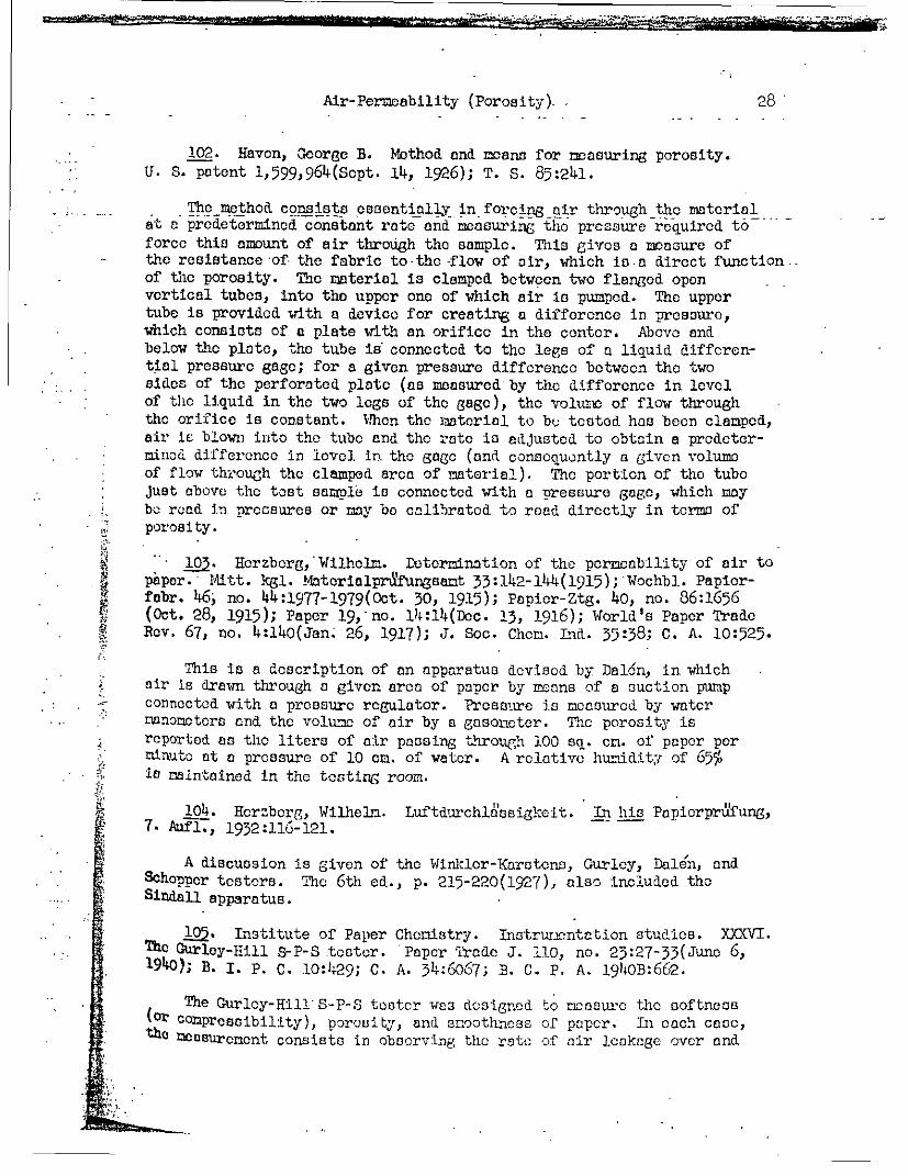
Air-Permeability (Porosity). 28
102. Haven, George B. Method and means for measuring porosity.U. S. patent 1,599,964(Sopt. 14, 1926); T. S. 85:241.
The method consists essentially in forcing air through the materialat a predetermined constant rate and measuring tho pressure required to force this amount of air through the sample. This gives a measure ofthe resistance of- the fabric to-the -flow of air, which is-a direct function--of the porosity. The material is clamped between two flanged openvertical tubes, into the upper one of which air is pumped. The uppertube is provided with a device for creating a difference in pressure,which consists of a plate with an orifice in the center. Above andbelow the plate, the tube is' connected to the legs of a liquid diffcren-tial pressure gage; for a given pressure difference between the twosides of the perforated plate (as measured by the difference in levelof thc liquid in the two logs of the gage), the voltui of flow throughthe orifice is constant. When the material to bu tested has been clamped,air is blown into the tube and the rate ia adjusted to obtain a prodeter-mind difference in level in the gage (and conaoquontly a given volumeof flow through the clamped area of material). The portion of the tubejust above the test samole is connected with a pressure gage, which maybe road in pressures or may be calibrated to read directly in terms of
. porosity.
' 103. Horzberg,'Wilholm. Determination of the permeability of air topaper. Mitt. kgl. Matorialprufungsant 33:142-144(1915); Wochbl. Papior-fabr. 46; no. 44:1977-1979(0ct. 30, 1915); Papier-Ztg. 40, no. 86:1656(Oct. 28, 1915); Paper 19, no. 14:14(Dac. 13, 1916); World's Paper TradeRev. 67, no. 4:140(Jan; 26, 1917); J. Soc. Chom. Lnd. 35:38; C. A. 10:525.
This is a description of an apparatus devised by Dal6n, in whichair is drawn through a given area of paper by means of a suction pumpconnected with a pressure regulator. Pressure is measured by waternanometers end the volume of air by a gasoncter. The porosity isreported as the liters of air passing through 100 sq. cn. of paper perminute at a pressure of 10 cn. of water. A relative huniditr of 65%is maintained in the testing room.
104. Horzberg, Wilhelm. Luftdurchla'ssigkeit. In his Papiorprufung,7. Aufl., 1932:116-121.
A discussion is given of the Winl;lor-Karstons, Gurlcy, Dale'n, andSchopper testers. The 6th ed., p. 215-220(1927), also included theSindall apparatus.
105. Institute of Paper Chemistry. Instruncntation studies. XXXVI.The Gurley-Hill S-P-S teeter. 'Paper iradc J. i10, no. 23:27-33(Juno 6,1940); B. I. P. c. 10:429; C. A. 34:6067; B. C. P. A. 1940B:662.
The Gurlcy-HillS-P-S tester was designed to rcosurc the softness(or conpressibility), porosity, and s3rnthness of paper. In each case,the mDcsurneent consists in obsorving the rate of air leakage over and

Air-Pcelneability (Porosity) 29
through the paper specimen. Uniform air pressure is supplied by meansof an inverted hollow piston floating freely in a cylinder partly filledwith oil. The air is forced downward, through an open central tube,to the upper orifice plate against which the sample is clamped. Inter-
_ hangeable lower test.plates provide for measuring the various properties.. Uniform clamping pressure is provided by cans of a lever; one end. upportsa...
the lower plate and the other end supports weights calibrated to give the.... -_ . .i --desircd--prossure on--the-paper. -The--rate- of--air-leakage over-or through- - -- - -
the specimen, depending upon the property being roasured,_is determined.by timing the novomcnt of the graduations on the piston as they pass theupper cdge of the butter cylinder. For those prosity tost, a perforatedlower plate having a plane annular ring, stated to be optically flat,is used. Air escapes downward through an area of 1 square inch of paper.The specimen is clamped between the two plates,- either by using the capstanscrew or the lever arm with the 2-pound weight. The porosity value is ox-pressed in terms of seconds per. 100 cc. of air flow. The results areclosely comparable with the Gurlcy denoemotor readings. The readings areaffected by lateral air leakage.
.. '106. Ivanov, N. D. Determining the porosity of paper.. BumzhnayaProm. 2, no. 6:698-700(1923); World's Paper Trado Rev. 83, no. 8:634(Feb. 20, 1925); T. S. 79:147;. C. A. 18:2074.
The apparatus consists of a omasuring'cylinder, to the top of whichare fitted two metallic rings (to hold the sample) by means of rubbercollars. A tube leads from the top of the cylinder to a mercury manoneterend also to a safety flask, which is connected to a suction pump. At thebottom, the cylinder is connected to a vessel containing mineral oil andto a mercury manometcr. The time taken for a given quantity of oil toenter the cylinder represents the porosity of the paper. The differencein the rondings of the two manonotcrs is the absolute pressure during thetest. The apparatus is sinplor than that of Dal6n. and permits workingwith pressures up to 0.5 atosophreo.
107. Jahnns, Gordon A. Porosity. In his Paper testing and chemistryfor printers, 1951, pages 99-101.
Detail are given of the British Electrical and Allied IndustriesRoeearch Association rules for testing the porosity of paper. The test
-- i..: s based on the Mariotto flask method.
- 108. KozarovitskiX, L. A. An investigation of the molecular nature'..:ed dispersity of printing papers. Colloid J. (U.S.S.R.) 3:507-521(1937);
[-.*t', AC. 32:6128; B. I. P. C. 9:76.
The rate of absorption of water or toluene by paper at the water-- '^! or tolueno-air interface or of the selective absorption at the water-
t* oa6en 0 interface acrvos as a ecasuro of the degree of dispersity of the; fiber in the paper (i.e., porosity) and gives an insight into the nature:.o tho fiber. '
2rW > .^-. Krauss; R. A. Porosity and density measurements of paper...t.ci atically rcltod. Papicr-Fabr. 29, no. 23A:96-97(June, 1931);
;tP Paper Mag. Canada 31, no. 38:1054(Scpt. 17, 1931); C.. A. 25:5988;s 93:276; 97:131;. B. I. p. c. 1, no. 12:27.
V

Ir ··-~~~~~~~~~~~~~~~~ .. -.:i'q. t.E,-. . - , .... , ,, -,
Air-Pcrecability (Porosity) 3o0
In -thc Schopper porosity tester, the porosity S is dcrtcmined byncasurin C the volume of air (cc.) which passes through an area of 10 sq. cn.Ilhriig 1 minute at a constant pressure cf 10 cm. of water; with the Gurloy
-dorson:otor, the toet comprises a-dotcrninationofthc nmubcr of secondsrqrequi;ecd by 100 cc. of air to pass through an area of 1 sq. in. at acalculated pressure of 3 ounces per square inch. A theoretical relationbetwcEn'-thls Otwo value-iso (C992/S) - - = O; -actual tests- ive the rela-tion (7300/S)- G = 0. The difference .may be the result of the fact that-the specific rcoasure exerted by the weight of the imlorsion cylinder inthe Gurley apparatus is reduced from 13.3 to about 12.8 grars per squarecentimeter because of the buoyancy of the cylinder when inrersod. Thisass-ption makes it possible to derive the Gurloy doenonoter values byeaons of the Schoppor apparatus; the pressure is adjusted to 128 il. ofwatcr, and the tine required to displace 155 cc. of water is measured.rnc larger anount o0 water roquiroa copcnas upon th cailrrcronco in theareas of paper employed for the test.
110. Lhonnc, H., Argy, M., and Bard, P. The porosity of paper to air.Papoterie 53, no. 23:1438, 1441-1442, 14 4 5(Dcc. 10, 1931); Pulp Paper Canada33, no. 4:177-179(Junc, 1932); C. A. 26:1779, 4717; T. S. 94:191; 95:235;Paper Ind. 13:1471, 1473; B. I. P. C. 2:204. '
The Lhonno and Argy porosity testor is designed to measure the timrrequired for the passage of 100 cc. of air through a sheet having an areaof 50 sq. cn. under a constant pressure difference corresponding to 10,20, 50 (and in exceptional cases 100) rm. of water. Tests carried out withseveral instruncntc on three grades of paper showed that (1) the instrumentis free fron any i-nherent errors resulting front a lack of sensitiveness andgives constant results with the same paper under constant difforcnces ofpressure and constant hygroscopic conditions; (2) with grades of paper wherethe ?roportionality between the tim required and the difference in pressurehus becn tested (i.e., for most paper to which the porosity test is generallyappieod, except for thin condenser papers), the nost cornvoniont pressuredirfcrence (between linits of 10 and 100 nn. of water) car! be used; and (3)the sane sample of paper give, comparable results when tested under differentpressure differences. The instrument comprises a countcrwcighted cylinderpartly immersed in water. The top of the cylinder is closed by the testpiece, clamped bctwocn two carefully machined rings. The cylinder is sus-Ponded by ncans of a perfectly flexible ribbon passing around a large pulleyWhlch is mounted on very sensitive ball bearings. The counterweight atthe other end of the ribbon not only balances the weight of the cylinder but,t An addition, can raise a column of vater of a given prodotoerlinod height
': ' tn0aid c the cylinder, thus producing inside the cylinder a partial vacuum.eq' lvalcnt to this column of water. As air passes through the paper into
the cylinder, the latter rises. As the counterweight keeps the height ofthe lquid inside the cylinder constant, the height through which the
;. i-e;tcr rises gives an exact emasurc of the quantity of air passing through.8per. A long balanced pointer anolifies the displaconont of ther ,W4f&cx.r. 'which is read directly on a .0le.
't~,,e :-
. Q.xX.
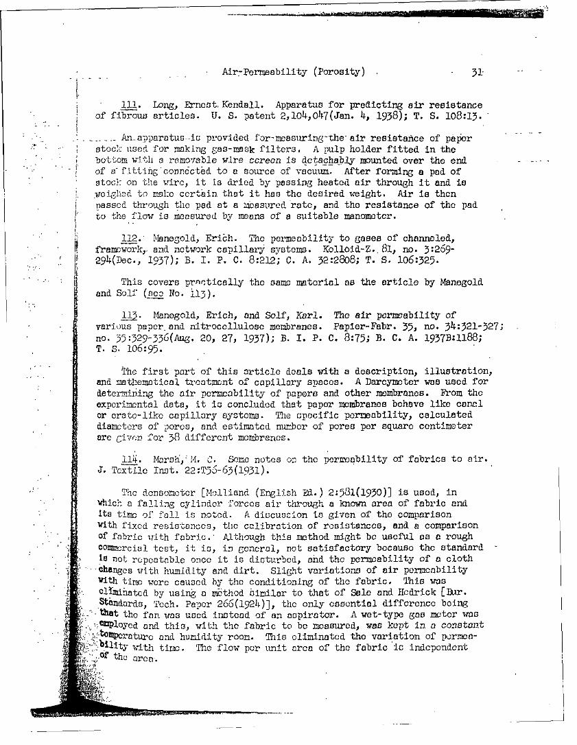
Air-Permeability (Porosity) - 31-
111. Long, Ernest Kendall. Apparatus for predicting air resistanceof fibrous articles. U. S. patent 2,104,047(Jan. 4, 1938); T. S. 108:13.
:* - ' 7 Aapaparatus-is provided for-measuring-the-air resistance of paper; stock used for making gas-mask filters. A pulp holder fitted in the
bottom with a removable wire screen is detachably mounted over the end - -of a fitting connected to a source of vacuum. After forming a pad ofstock: on the wire, it is dried by passing heated air through it and isweighed to male certain that it has the desired weight. Air is thenpassed through the pad at a obasured rate, and the resistance of the padto the flow is measured by means of a suitable manometer.
112. Manegold, Erich. The permeability to gases of channeled,framework,. and network capillary systems. Kolloid-Z.. 81, no. 3:269-29 4 (Dec., 1937); B. I. P. C. 8:212; C. A. 32:2808; T. S. 106:325.
This covers prnctically the same material as the article by Manegoldand Self (seo No. i13).
1 ). Manegold, Erich, and Solf, Karl. The air permeability ofvarious paper and nitrocellulose membranes. Papier-Fabr. 35, no. 34:321-327;no. 35:329-336(Aug. 20, 27, 1937); B. I. P. C. 8:75; B. C. A. 1937B:1188;T. S. 106:95.
The first part of this article deals with a description, illustration,and mathematical treatment of capillary spaces. A Darcymoter was used fordetermining the air permeability of papers and other membranes. From theexperimental data, it is concluded that paper membranes behave like canalor crate-like capillary systems. The specific permeability, calculateddiameters of pores, and estimated number of pores per square centimeterare given for 38 different membranes.
114. Marsh,iM. C. Some notes on the permeability of fabrics to air.J. Textile Inst. 22:T56-63(1931).
The donsonoter [Molliand (English Ed.) 2:531(1930)] is used, inwhich a falling cylinder forces air through a known area of fabric andIts time of fell is noted. A discussion is given of the comparisonwith fixed resistances, the calibration of resistances, and a comparisonof fabric with fabric. Although this method might be useful as a roughconcrcial test, it is, in gencral, not satisfactory because the standard
* , I not repeatable once it is disturbed, and the permeability of a clothChanges with humidity and dirt. Slight variations of air permeabilitywith time were caused by the conditioning of the fabric. This was
' .clnminatcd by using a method similar to that of Sale and IHcdrick [Bur.Standards, Tech. Paper 266(1924)], the only essential difference being
f .- that the fan was used instead of an aspirator. A wet-type gas mother was.e*Cployed and this, with the fabric to be measured, was kept in a constant
: ,. tpoxraturo and humidity room. This eliminated the variation of pormoa-lbility with time.. Tlhe flow per unit area of the fabric is independent]O'f the area.
j*BQIPIpIfarwassciH·v- wn'w' r - ----.

_.. ....... -Air-Permeability (Porosity)- - _ _,
115. Micoud, Henri. Physical properties of paper. Porosity--pDrmeability. Papier 32, no. 11:1143-1146, 1149(Nov., 1929); Zellstoffu. Papier 11, no. 2:79(Feb., 1931); B. I. P. C. 1, no. 7:14.
A general discussion is given, including descriptions and illustra-_..... ._ _: tions, of the methods of_Sindall, Winkler-Karstens, Schopper, and Carson.
'116. Noll,j August. Sheet density as an index of the porosity of -pulp. Papier-Fabr. 34, no. 4:25-27(Jan. 26, 1936); B. I. P. C. 6:314;B. C. A. 1936B:230.
The author develops a number of equations for calculating the volu-. metric weight, the fiber fraction,. and the air fraction or porosity from'," the apparent density or bulk of a pulp sheet. A table is included
showing the relationship between density;, .olumetric weight, percentage-i of fiber fraction, and perc.lntage porosity.
117. Paper Makers' Association of Great Britain and Ireland. Techni-cal Section. Paper Testing Conmitteec. The air permeability test.Specification of method due to T. Trevor Potts; specification of methodusing the Gurloy densometer.. Proc. Tech. Section, Paper Makers' Assoc.Gt. Britain Ireland 18, part 1A:54-61, 62-66, 116-125(June, 1937); World'sPaper Trade Rev.., Tech. Convention No., March, 1937:46, 48, 54; discussion,48, 53, .56, 58; B. I. P. C. 7:348, 349.
The Potts permeability tester (illustrated)(soc No. 119) consistsessentially of a suitable means for clamping the paper so as to expose10 sq. cm. on one side to the atmosphere and on the other to a perfectlyclosed system through which air may be drawnm under constant head by meansof a water aspirator fitted with a Mariotto tube, the outflowing waterbeing measured in a suitable vessel, such volume being equal, under theconditions of test, to the volume of air which passes through the testspecimen. The air permeability is defined as the rate of flow of airthrough the test specimen in ml. per minute under a pressure equal tothat of a column of water 10 cm. in height. There is an approximatelydirect relationship between the rate of flow of air through a sample ofPaper and the pressure difference. Under the conditions of the test,any flow of air through the edgos of the test piece is negligible com-pared with the flow at right argleo to the plane of the shoot. Thesecond article gives details of operation for determining the air per-meability with the Gurley dcrsomotcr. Small variations in viscosity ofthe liquid used (light paraffin, light mineral oil, thick lubricating oil)do not have a- substantial effect; when ae stead rate of fall is established,
Aen,~I: k"' - 4
WMWWMMFMUMMCMM-------^_~- II_ ~__--_
.32.
Air-Permeability (Porosity) 33
similar readings are obtained over a wide range in viscosity. A changein pressui'f id negligible in its effect, except for very accurate work.Where rough papers are being tested, there may be a distinct error intro-duced by leakage between the container top and the paper surface; severalusers recommend a rubber_gasket cemented on the top of the container andhaving an accurately cut hole coinciding with the hole in the container.
113. Porosity-apparatus. -World's Paper-Trade Rev. 82, no. 26:2122(Dec. 26, 1924).
A brief description and illustration arc given of the Schopper porosityapparatus.
119. Potts, T. Trevor. The volumetric composition of paper. I. Thepermeability of paper to air. World's Paper Traide Rev. 95, no. 15:1257-1258, 1260, 1262, 1264, 1266, 1330; discussion, no. 20:1762, 1764, 1766,
b- *1768; no. 21:1818, 1820, 1822, 1825(April 10, May 15, 22, 1931); Paper-- * Maker 81, no. 5, suppl. :cxlix-clii; discussion, no. 6, suppl. :clxxxii-!' clxxxiv; 82, no. 1, suppl. :xi-xiii(Moy-July, 1931); Annual No., 1931:56-57,
59, 61-62; zollstoff u. Papier 11, no. 12:700-701(Dec., 1931); Proc. Tech.Section, Paper Makers' Assoc. Gt. Britain Ireland 12, part 1:91-106; dis-cussion, 106-122(0ct., 1931); B. C. A. 1932B:177; T. S. 93:102.
The apparatus consists of an aspirator with a Mariotto constant headdevice (see No. 95, 117, 120, and 125). The paper is concerned prindipallywith a discussion of the effect of changing conditions of test on the rateof flow of the air through the sample; these include the area of thesample, the pressure, and the thickness of the sample. The rate of flowof air through a given sannmc is proportional to the area of the sample(an exception is for large aroas of papers of low permoobility). The rateof flow is very nearly d iroctly nroportion:l to the applied pressure.The rciat of flow i: not di:c-.y p.roportic:,a] to the cuzmber of thickncsscsbut always to some power of the k vue of te owrvarying according to the cmniplc of paper tcIstr; thvs, the flow is afunction of the interfiber space. dtosin sizing is saicl to affect pormuabili-ty only slightly. Fillers in most cases increase permeability.
120. Privott, Ivan B. Permeability tcst on waterproof boards.World-s Paper Trade Rev. 95, no. 17:1436, 1438(April 24, 1931); T. S.93:195; C. A. 25:5025.
The test is similar to that described by Potts. An inverted burot issot with its mouth Just below the water level in' reservoir, the latterbeoin connected by a rubber tubing with the cylinder, on the top of whichlt[ the test sample. As the water in the reservoir falls, the burot dropsc few cc. of water, bringing the level up to its mouth; thus, the correct-evcls are automatically maintained. The buret empties by a series ofbubbles at moro or less recm.lar intervals; for comparative tests, it is
: * sufficient to take the time interval between the first and last bubbles andto read the total volume of water dropped from the burot (this equals the
: iVolume of air forced through the test specimen). Tho test varies with' " Qthe direction of the passage of the air through those board.
,~ :A! -
rami

PI-
* O
IN
--4'
C) t
6-
V401
.4 ...
00030P
L
4'H
0
ft..0
i0
Cm
44
0G0
I00
*4.0DC
)'
.4300
0-$0)
ICq
-I
H C
8co
4
r$4b )
0Id,
PIC;
CC' H
~4-4
H46-
WN
43
,4~
-4--
m
u C
\
Pt f
7%.-
o i CO
A
SC
D-
'C
Id
H
"0G
Nr4
i _1)zr X
.yp0
30)$4
03C;
4303CO
$4
02-CG
o
'CItIC5-Ai4i
C3C
A 44
~0
c4
(D C
I434roj
$4
04
401C
)
4P
'
.40-IdC)
PaC)
C4a;
'cC4-CCCC4ii'1 'dO'-I 4
H43
0 04
+34~4o
M
CO
$4
Ca,0$4'd
4.4
L1 H
) C
)H
C!.42~.0) m
-
H~
C~
Itaa.4.
4-
C
C)
~~~C)
4 4-
(0t
4)~ l4~
H
A04)
C
)C4*i-
r-P
-40
0 4f$
'.4
'd-
'-0~~
'
44
003.
0o~
~~
~oI
~~0i~~
~~6 0) 00 4
044
-4 & ~~C) n
#4
c
14 C
4
O *rI
*r-4 -
4Av
PC
D204
0.0C
r4
pm
CD
$4J04)
03
-43
'0443
30-ID
C-,
4-44
0 0 C
3 -
H-
43
05C
C)
,
40
'-
(
ci04-'
-4C-1
C3
5.44
v0~~~,
$4
0.4
to
E6-IC
4I-4
.43
$44o
C) O
0
0 04
$4 *0
I -D
i
03L
0-P*H
t 4
5'C
mi
30C-40
-40'
ci 4
4'
O
00
I5.4ED
03I4-
0CO
~4>04
0)
A6-0
C)00
3C)
%.f
CDONci
N034aV5$4
C)
4.,03C14030$4e
CCPHO
N
4-
'H,
us-C
"
ooq21 tIH
:-" -
i A
S
_
-.--
-=tE
CC'CIPI
I
DtItCiiII
I f

iO
03~
.a) 4343
02
4dr
'1)
>)
.4-1
~4
oo0
a)3 4
--
oo
00 00
H
4 ' C
4 W
HH
$4
ro
Q4
4M
043
wad
4'24>
202 c
co D
0>
DI
C
0)
$4
'0
0) 43
0
'H 4
4)C-4
$40 'd
4-' 04
.00
t
coi
coo
044-
co 40 0
0.0 4 4
PI
P.,I
0000
>003
002C3-
iC)
94-03
0)
ci
coo
40
43 0
C)
a)
.0
*432$. C
MJ
P.
04'
ri$4 ~E
D4 43
tC\
-4-4
5E
fl
$4 '-
d O0
'* 0
04
cli~
~~
~-
o 0
t1 8
0 ~
03
0 00)
Or)
I-iM
20043 43
aH
03C
O43
,- .2 -m
C- H
O
40-
-0
404 -
S >
0
ag c
OH
00 t
0 CC0
S..
dO
4- PC
H
O
C
4'Si 0
043 dxl
U 2 H
0
-i 0
o~
0-5'd04
0 )
0 3
H
-
0 $4
n4
04.w
od w
co 4) C
) .
490 S
0P
P.
0I d
:t 0
3
0
0t
P4 H
f
T-
o '-
rC
r-l t
0...
tO \
.
.'N %
co
$~4 N
- Zn
CC)oH
H '
-0 H
coPIC
lr-I
CC
) *
Ci0a
P.
ri04-HH0
4'
0)
ci>23-A
00
43300'CM
0 0
09.0
MW
4-)0)
3-P
0OO
r4 ~
0C
020.5.
-PZ
*0 41
10
a4d$4
00
0P
43
0CM
-P,-4i
00
>243
P4 .
C r-i
i 0
002C'
? co
H
i 443
4 4 3 C
0 0 4
3 4 -'
P ,
o P
-0
-P 0 0
0 2
0 2
P, 0
C5
4
H
P4
*
0
H O P
0 0 4
3 -I 0
0 C
f 0 >
2
-M
4 3 0 .
.P
4* 43
-H
4 r-0
>2 C
) d
H
, ;
5 H
0
) H
44 3
-03
-4
0 0
.
0 C
5 -P
4H
O
%
0 -
Q
4 3
O
0 O
r r-AP-
020)
P0 4 -i
3 i
-H
-H
0MM
-H
d4
~ C
o .
H-
) 0 0
4 3
2 C
'C
C),,G
~ 0)t
C f l
M
0 4 3
$ 4
-' -
H
r -2 04
Ci 4-
C4- )
.5 a
-I -
C
0 0
2 , 00)
C
0 2 -
4 -
0) .
e~30
234j X
i Z
m
'.0 t
FC1 -H
.
4 -.
3- C
O d ~
' 04
K'
4 C
AX
4
0 C
0c
-P Li P
H O
-
0.0M
co
d '4 C
,,c i
b C
IA-
C0
H
P
C)
H
$
C),
-' 4
g.§ x
C) I H
0
C
>n-H
P
3 4 4 0 )
0 4
0 .H
4 '
' 44
4 .
0 0-4
0 Q
z .
34.
H0
MC
)V4
~
.
0 ~ ~
~ 00
4-ip.
C0P
4s >4
2oH
04
' t- C
4 3 -5 C
£ -H
O
H
Z~H
C
>
0
0 0
024
.0 C
o d r
~ n
om4
O0J -;'
CH
-I
C )
4 0
\ j t
i l
, C
~~~~4 0~r4
r C
4-'3 0'd
~
r-A04-
C
--
--
S ' 8
ef2 A
• -
" --
A7.
.-.- ,
�I
Air-Pormeabf (it'Y"Qz1"^^ ' 1' T
129. Sindall, Robert W. Some physical properties of paper. I.Porosity. World's Paper Trade Rev. 55, no. 16:737-738(April 21, 1911);Paper Making 31, ho. 9:344-345(Sept., 1912); Papier-Ztg. 36, no. 42:1524(May 25, 1911); Pulp Paper Mag. Canada 10, no. 8:253-254(Aug., 1912);
*-: Paper 8, no. 7:25(July 31, 1912); C. A. 5:2944.
The apparatus consists of an inverted cylinder, the sample being._.. clamped at the upper end; thesample rests upon a rubber ring and is held
in position by a brass ring. Water is introduced into the lower partfor -neck of the cylinder through a siphon tube inserted in a rubber stopper.Porosity is defined as the number-of minutes for the passage of 100cubic inches -of air through an area of 10 square inches of paper.
L;1. Stocwer, Walther. The porosity of paper. Wochbl. Papiorfabr.64, no.'4:57-59(Jan. 28, 1933); Boll. staz. sper. ind. carts 12, no. 3:30-32(March, 1933); C. A. 27:5973; T. S. 98:14.
The Schopper porosity tester was used. Air transmission is propor-!' tional to the pressure head. It decreases slowly during the first part
of a test with a porous paper. The porosity increases 15-50% between0 and 100% relative humidity with porous papers, but decreases with very
: | dense papers. Porosity decreases rapidly with increase in sheet densityin all cases.
151. Strachan, James. Porosity and air space of paper. Paper-Maker81, no. 1, suppl.:xli-xliii(Jan., 1931); T. S. 92:345.
This article gives a general discussion under the headings: difference:: *between porosity and air space, practical importance of porosity and air
space, methods of manufacture and control, and methods of testing. Men-tion is made of the donsometer, which is practically the same as theWinkler-Karstens apparatus, anrc more precise instruments, which consistof two parts: (1) apparatus for producing a measured flow of air at aconstant pressure by means of a Mariotte type of control, and (2) appara-tus for clamping a disk of paper of standard area over a chamber intowhich the flow of air is maintained; this is exemplified in the Schopporporosity tester. This type of apparatus presents several faults, whichare enumerated., Corrections and methods of control arc outlined, bywhich the instrument will give useful reading!" for porosity of the majorityof ordinary papers where the permeability varies from 0.5 to 5 liters ofair per minute under standard conditions.
132. Sweeney, Orland R., and Arnold, Lionel K. Studies on the manu-facture of insulating board. Iowa Eng. Expt. Sta., Bull. 136. 1937. 75 P.
An apparatus for the infiltration of air through insulating board isdescribed. This is the method described by Arnold [No. 76].
.i e" 132A. TAPPI. Air permeability of paper. TAPPI Standard T 460 m-4 3.·:. , 'i^i sheet.
A,:* ~ !. The apparatus consists of an cuter cylinder, which is partly filled- ;/?with oil, and an inner cylinder, having a closed top, sliding freely in the
g.oujter cylinder. Air pressure for the test is furnished by the weight of thei, inner cylinder. Details of the apparatus and procedure are given. Air
:: oermpability is defined as the number of seconds for the displacement ofvO1 tm. of air through an area of 1 square inch of the paper.
.;
I-C-Il __

37
BASIS WEIGHT
-1. American Society for Testing Materials. Tentative methodsof sampling and testing untreated paper used in electrical insulation.A.S.T.M; Designation: D 202--41 T. A.S.T.M. Standards 1942, Part III:1187-1206; A.S.T.M. Standards on electrical insulating materials, Feb.,1944:373_-392.
Basis weight is discussod on pages 1189-1190 of the first reference.
134. American Society for Testing Materials; Tentative method oftest for basis weight of paper and paper products. A.S.T.M. Designation:D 646--42 T. A.S.T.M. Standards 1944, Part III:347-349; A.S.T.M. Standardson paper and paper products, Nov., 1943:93-95.
This is TAPPI Standard T 410 m-41.
135. Author Testing Instrument Co., Inc. Direct reading quadranttype scale. Circular No. 8. n. d. 1 sheet. Direct reading paper re-du6tion scales. Circular No. 11. n. d. 1 sheet.
Illustrations and a brief description are given for a desk modeland a pocket model.
136. Carson, Frederick T. Maintenance, calibration, and use of papertesting instruments. Paper Ind. 16, no. 9:621-626(Dec., 1934).
A method is given for calibrating a ream weight balance. Such abalance should respond readily to an increment of 0.1 gram. It is ad-visable to weigh enough paper to give a reading on the upper half ofthe scale. To yield results of the accuracy required by the TAPPI Stan-dard, the sheets weighed and measured should all be at least 8 inches wide.A magnifying lens is required to read the measuring scale. Both dimensionsof each sheet should be measured twice, near opposite edges.
137. Harrison, V. G. W. Substance. Patra J. 2, no. 3:118(Nbv.,1938).
Although special balances arc available for determining the substanceof paper, Petra uses an ordinary chemical balance for this purpose. Aknown area of paper is weighed in grams, and the substance is expressedas grams per square meter or in pounds per ream of a designated size.
[:' 13-. Houston, Paul L., Carson, Frederick T., and Kirkwood, R. S.: BEfect of atmospheric humidity in the' physical testing of paper. Paper Trade
;-76, no. 15:237, 239, 241, 243; 245, 247, 249, 251(April 12, 1923);Tech. Assoc. Papers 6:64-71(June, 1923); T. . 77:1; C. A. 17:2501.
Data are given for the basis weight (employing a quadrant scale) ofi iU;papera determined at humidities of 15 to 83%. All curves are of
a, ttsame type, the slope and curvature for corresponding points varying
:i>htlya' from paper to paper. The effect of humidity varies to aor less extent with the kind of paper tested. As would be
*Pcted, the curves are similar to the moisture content curves.
i *
III �OaL -- ------ -
Basis Weight
13~ Institute of Paper Chemistry. Instrumentation Studies. XII.Effect of relative humidity on physical properties with respect to thehysteresis effect in changes from one humidity to another. Paper Trade J.104, no. 15:45-48(April 15, 1937); B. I. P. C. 7:314; B. C. A. 1937B:657;C. A. 31:4813.
Data are given showing the change in basis weight (using 65% relativehumidity as the base line) when the samples are humidified at 40, 50, 65,and 757 relative humidity (ascending-series) and 'at' 75, 65, 50; and 40% relative humidity (descending series).
140. Jahans, Gordon A. Weighing and measuring. In his Paper testingand chemistry for printers, 1931, pages 76-81.
The quadrant and demy balances are mentioned. Other balances includethe Thwing basis weight scale, the torsion balance, and the pea andbeam scale.
141. Krottschmar, W. Now special scales for mill control in a papermill. Wochbl. Papierfabr. 63, no. 32:609-611(Aug. 6, 1932); T. S. 96:269.
Four types of scales of German manufacture are illustrated and brieflydescribed.
142. Kratschmor, W. Paper investigations. Paper scale, moisturetester. Wochbl. Papierfabr. 64, no. 48:864(Dcc. 2, 1933); Pepier-Fabr.31, no. 10(Amt. Tcil):ilO-112(March 5, 1933).
- - An illustration is given of a paper scale manufactured by MersoburgerWaagonfebrik, A. Dresdndr, Morscburg, which is based on the plus-minusmethod; it shows the variation in the weight to an accuracy of 0.1 gramor 0.2%.
1i. Thommc, H., and Argy, M. Weighing of papers and cardboards.Papcteric 43, no. 20:1010-1014(Nov. 25, 1921); Paper Trade J. 74, no. 19:58.
A description is given of a quadrant balance equipped with ball bear-ings. With a 3-kg. board balance, a load of 0.1 gram caues an appreciabledeflection.
144. Lhommo, H., and Argy, M. The weight of paper. The method ofmaxima and minima. Papetoric 54, no. 20:1114, 1117(Oct. 25, 1932); C. A.27:20O8; T. S. 97:72.
Two cursors are provided which may be adjusted along the scale of aPaper balance and sot at the maximum and minimun tolerances, respectively,*or a given order of paper. If the actual weight of the paper does notfall exactly as prescribed, it can be seen immediately if it falls withinthe permitted limits.
t 1;. 14. ' Loobo, R. M., and Loebe, W. W. Sensitive balance for detormin-S gt the uniformity of papers. Zcllstoff u. Papier 15, no. 4:146-150(April, 1935); T. S. 103:27; C. A. 29:4938.
f'b
CI�-Y----·-I`---W··I---r�·LIIIC-··L ·.· ·-·L-l�
*..ta �aDI
38
Basis Weight 39
A sensitive balance. is.described on which paper can be weighedmore accurately, especially the lower weights. The instrument is easyto use and is low in cost. The principle of the balance is describedby means of illustrations and diagrams.
146. Paper Makers' Association of Great Britain and Ireland.Technical Section; Paper-Testin Committee; Paper substance (roam- --weight) detei-mination. Proc. Tech. Section, Paper Makers' Assoc. Gt.Britain Ireland 18, part lA:7-lO(Juno, 1937).
It is recommended that the test sheets should not be less than10 x 10 inches, but if smaller sheets are employed, special care must betaken that the samples, are accurately cut and weighed on scales conform-ing to the specified limits of sensitivity (at least 0.25% of the loadapplied). The Schoppr quadrant scale nd the "bit full-sht scaleare illustrated. Methods of calculation are included.
147. Physical testing of paper. Basis weight. Thwing's Paper Tester1, no. 1:1-4(1936).
Two methods arc discussed: the use of a scale or balance weighingin grams or grains and the use of a ream weight scale. The Thwing beamquadrant scale is mentioned. A table of humidity corrections for basisweights is given.
148. Platform scales for handmade board. Wochbl. Papicrfabr. 70,no. 34:754; no. 39:821(Aug. 26, Sept. 30, 1939); B. I. P. 0. 11:37.
Rapid precision scales are manufactured which are suitable forweighing thin handmade boards; the platform is approximately 80 by 100 cm.
149. Sindall, Robert W. A now paper scales. World's Paper Trade Rev.57, no. 26:1302-1503(Junc 2°, 1912).
This scale is a modification of the ordinary demy balance, constructedin such a way as to give the weight of paper fron a small piece, by adirect reading of the scalo. It is designated as the "Univjrsal paper scales.
150. Sindall end Bacon.; equivalent weights per ream. Paper Maeors';M. J. 53, no. 5:146-147(May, 1915); 0. A. 9:2311.
The authors review six methods for determining the equivalent weightper roam. They suggest the use of a definite relation between unit areaand unit weight.
151. TAPPI. Basis weight of paper. TAPPI Standard T 410 m-44.1 Page. Paper Trade J. 75, no. 3:45-46(July 20, 1922); 84, no. 4:48(Jan. 27,1927); 99, no. 21:42(Nov. 22, 1934).
The basis weight is dotermined.by dividing the weight by the area. Itl reported as the equivalent ream weight in pounds for a roam consistingt 500 sheets, 25 by 40 inches; the weight in grams per square motor of
I P1pr; or the equivalent weight for the roam size commonly used by the paper
iA4k
I. -A1.'i,>l '1,,_~ gllb~aa ~n -- ·1a irn I r~ a lop

iii~.Y~:~~---^Tr~' -^i~a~f~ :HM *:,! ': ..̂ i...~ .~ -.... ...~ ~. ...... j ~" ......~ .,r~I
Basis Weight 40
industry for the particular kind of paper. Formulas are given for convert-ing the weight obtained on a gram balance or on a paper scale into weightin pounds (25 x 40--500) or in grams per square meter. A conversion tableis given for converting trade sizes to the above sizes.
1* 152. Thwing Instrument Company. Thwing basis weight scales. Bullc-tin 19, 1928. 12 p.
-A general description is given'of the types of scales manufactured by -the Company, with directions for their use. [Sc also No. 147]
: i 153. Toledo Scale Company. Toledo paper roam and box board auto-gages. Form 8651. Juno, 1935. 4 p.
An illustration and a brief description of the scale and its opera-tion are given.
154. Torsion Balance Co. Paper and pulp testing balances. BulletinNo. 542. July, 1936. 4 p.
An illustration (but no description) is given for a basis weightscale. The scale is made in two styles, with one and two beams.
155. Tuna, Vladimir. The use of circular cutter in the determina-tion of ream weight. Paper Trade J. 99, no. 25:31-32(Dec. 20, 1934);B. I. P. C. 5:128; C. A. 29:1631.
The E. C. R. cutter is designed to cut a circular section exactly1/400 square yard-in area; the radius is accurate to +0.002 inch. Therecommended procedure is to cut out at least ten circular sections fromvarious portions of the paper sheet to be tested, to weigh them accuratelyon an analytical balance, and then to divide-the total weight by thenumber of pieces; formulas are given for converting this weight to roamweight. The advantage; arc: the equipment is very inexpensive; small sam-pies of paper may be tested accurately; the results are as accurate, if notmore so, than those obtained with the usual type of roam weight balance.

'41
BONDING STRENGTH (ADEESION)
A. Fiber-to-Fiber Bonding
This section contains only those teats which appear to be applicable
-- [-- to-paperboard.and does not attempt to cover the so-called pick test. Refer-.
ences to these may be found in Institute Bibliography 139-144, pages 21 to"
32. -
156. Abrams, Allen. · Bond. strength testing of boards and heavy weightpapers. Paper Trnde J. 91, no. 4:56(July 24, 1930); C. A. 24:5494; T. S.92:15p.
The method consists of gluing a 2 x 2-inch sample of the board se-curely between two blocks of wood, allowing the combination to sot for twohours under a weight of six pounds. At the end of this time, the bond strengthis determined by attaching the upper block to a' fixed support and applyinga load to the lower block until a break occurs. This load is weighed andthe bond strength calculated to a basis of pounds per square inch. Metalblocks were used at first but they were not entirely satisfactory for adherenceto the board; further it was inconvenient to clean the adhesive from theblocks. Therefore, seasoned white pine blocks were used, one surface ofwhich was carefully planed and sanded. Comparative results with N brandsilicate and a cellulose derivative ccmont indicated that silicate gave ahigher test after a short set but that, with either adhesive, the bondstrength incr-esed with a lengthened period of setting. The method detectsdifferences in runs of the same kind of board which might otherwise not benoted.. Bond strengths(pounds per square inch) f6r 0.016 test liners were19.4 end 11.3; for a 0.027 araft board, 18.3. -
According to a private communication received by The Institute of PaperChemistry in 1940, Abrarqs then used motel blocks for holding the paperepecimnns, meacurecd the splitting force with a tensile tester, and preferredGoodrich Vulcalock cement to sodium silicate.
157. Abrans, Allen. The splitting test. Tech. Assoc. Papers 13:39(May, 1950).
Abrams describes'a simple method in which a shoot of board is attached to carefully surfaced wooden blocks by means of silicate and allowed to standfor two hours under a definite weight. The shoot was broken by a rather crudeapparatus which consisted of a bucket into which sand was poured until the: hcat broke; this gave a measure of the bond strength. Tests were made withcellulose derivative, silicate, and casein glue. Silicate, properly applied.d seat under the right weight for the right period of time was quite setis-
factory.
. i'
I

Bonding Strength (Adhesion) 42
158. Bokk Ullstein paper-surface tensile strength testing apparatus.Advertising Leaflet, R. Fuess, Inc., n. d.
The performance of this instrument is based on the knowledge that the.tearing quality is defined by the strength (power) which is necessary to
. - - - - remove, under a-determined angle, a sample-paper-strip pasted-on a flatsurface.
Onr end of a 20 mm. wide strip of paper is paeted onto 6 brass stripholder with shellac. The instrument measures the force necessary to pullthis strip off at a given angle, the most suitable being 36 degrees. This
. force is taken as an indication of the resistance to picking or the forcenecessary to pull the surface fibers loose from the sheet.
k 12l9. Brown, Duncan S. The relation of the strength properties ofmulti-ply paperboard to the bonding between plies. Paper Trade J. 112, no.
.. 5 3:33-44(Jan. 16, 1941); Tech. Assoc. Papers 23:143-154(June, 1940); Paper: -d. 22, no. 8:844, 846, 848, 850, 852, 854(Nlov., 1940); B. I. P. C. 11:115;C. A. 35:3086.
The test in which the bonding between plies was measured by tearing the- v./-' sheets apart in the splitting operation has been designated as tho tcaring-
type bonding test. The tester designed by Courtney and Wakofield LNo. 161] and,'/ . *' modified by Forman Ltlo. 162A] was used in part of this investigation. On.
.·- '.;.- the whole, the tester worked well mechanically and gave moderately satisfac-.::.-' ' tory results. It was found that the initial splitting value was not roproduci-
-. -. * ble because of variations in the bonding brought about by the inserted stripused to start the snlit. In any test measuring the tearing split, the lengthof the split must bo sufficient to make negligible the effect of the insertedstrip or the ntarting of the split. The maximum and average forces obtainedfrom the curvo which results with the Forman tester arc the better means ofm- nauri;ig bonding; with this instrument. However, the evaluation of the re-sults is time concs'ing,E especially since a large number of teots are requiredto obtair a good average valuo. Therefore, a Schoppor tensile tester, whichwould measure a force between 0 and 1000 grams, was used to measure thetonsile force required to tear the sheets apart. The split was started bymeans of the inserted strips, the two sides of the strips fastened intothe clamps, and the tonsile force applied. However, this test was not sen-sitivc enough cnd the variations for any one shoot were quite largo. Amethod of measuring the integrated force required to split a definite areaof the shoot with the Elmondorf tear tester was also used. Strips 1 inchwide and with a splitting length of up to 5.5 inches can be used. Afterthe split was started, the heavy side of the sheet was clamped in the frontJaw of the tester, with the long axis of the sheet perpendicular to the planeOf motion of the sector--i.e., the sheet extended to the front. The otherSide of the shoot was hold in the fingers or a suitable clamp, the pondultunreleased, and the shoot split apart. Because of the simplicity of the
-* " test and the possibility of securing consistent results with-it, this tostiB recommended for all bonding measurements when it is desired to measurethe bonding force between any two given plies and not the weakest force .inte sheet. A perpendicular or normal bonding test similar to that used
, . bY Abramn [No. 156]was employed to measure the force required to split thei.~ s'het (either a solid or a multi-ply shoot) when the force is applied normal
* ,., l i
I
.: - .- *: " .. .a . - I, ", "SI
Binding Strength (Adhesion) -43
- to the surface. This test measures the weakest point-in the sheet.- Theadhesive used in this test depended on the nature of the sheet; if itwere a well beaten sheet, animal glue was used to obtain a strong enoughbond between the sheet and tile block. Silicate was generally used, how-ever, because it is sufficiently adhesive to be suitable for probablyall commercial boards and does not penetrate sheets of the porosity on-countered in this study. - - - -
_160. -Clark, James d'A.-Measlurement and influence of bonding be-tween paper fibers. Paper Trade J. 116, no. 5:29-35(Feb. 4, 1943); Tech.Assoc. Papers 26:462-468(June, 1943); B. I. P. C. 13:274; C. A. 37:2177;B. .. P. A. 1943B, 11:374.
The adhesion between fiber in a sheet of paper is dependent on theextent of fiber surface in actual contact, the strength per unit area
of the joints, and the flexibility of the joints. It is a complex quan-tity, and there exists no satisfactory means of measuring it directly.Various indirect methods for measuring it arc reviewed and two new methods,shear and split adhesion tests, are discussed in detail. The "% adhesionmethod, using a recently improved zero-span tensile attachment, is alsoconsidered. It would appear that the shear adhesion test is as satisfac-tory as any. It may be applied also for measuring the adhesion betweenthe plies of multicylinder boards.
161. Courtnoy, R. P., and Wakefield, H. F. Apparatus for measuringadhesion of dried films. Ind. Eng. Chom., Anal. Ed. 6, no. 6:470-473-(Nov. 15, 1934).
This method was developed for the testing of varnish films and wasthe basis of one of the methods used by Brown [No. 1.59]. Details aregiven of the preparation of tle varnish film on a steel panel and of meansfor tearing this foil 'rom the platc, nfter an end has boon loosened.
5162. Doughty, R. K., and Baird, P-. I. Solae factors affecting inter-web adhercnc of 1sngle plies used in laminated shots. Paper Trade J.97, no. 10:58-39(Sopt. 7, 1953);-Tcch. Assc. Papers 17:406-407(Junc,1934); C. A. 27:5975;'T. 3. 98:147.
The apparatus uced was simple and rather crude in design, consistinGin the main of an ordinary triple bean balance, but it gave quite repro-ducible and prcsvmably accurate results. The pan of the balance was re-placed by a weight, and a small hook aso hung from the pan support. Strips15 mn. wide were cut from the test plies and separation of the websstarted with the aid of the paraffined paper strip (inserted at the timethe plies were formed). One wcb wao fastoncd. to the hook, the other holdby the observer's firgers, and thc iorct just necessary to propagateseparation of thu pl.ic was detoerinod. This force was determinablewithin 3% without difficulty, and proved to be very nearly constant alongthe length of the test strip. It is assumed that this force is somefairly simple function of interweb strength.
162A. Forman, Loren V. Study of the bonding strength of adhesives.' :iSte'rs Dissertation, The InstitutO o-f Paper Chemistry, June, 1936. 87 p.
'U--
BiJRSZ�Wl�eff -·
ty i'

Bonding Strength (AM.hcsion)
. -- i; _ The .basic principle used in the construction of the apparatus was|l that used in the Courtney and Wakefield adhesion tester [No. 1611. The
sample tested was clamped in metal Jaws, as in the weight-pan method,but the line of pull was applied in a horizontal instead of a vertical
1, plane. The tearing force originated in a hand-operated windlass andwas transmitted through a coil spring by a stout cord to the jaws holding
... ... ;- . .-.. ono-end-of-the -test-specimonr.- One-end -of- tho-coil-spring--was--f-ixod-to-- -the frame which slid along a guide track as the cord from the windlasspulcd it along. _The cord leading from the movable end of the spring tothe test piece passed over a series'of pulleys in such a way that it '
; actuated a pencil which'slid along a track bri the frame at right angles --to the-direction of the motion of the-frame. As the frame was pulledalong and the spring stretched, the pencil produced a curve on a sta-
- tionary piece of paper clamped below the frame. As force was applied upto the amount needed to 'tart the tear, the pencil moved away from theguide track at the same rateoas the frame moved along it, the resultbeing a line which rose at 45 degrees from the base line. As tearingbegan, the angle of rise decreased and, if tearing was uniform, theremaindbr of the line was parallel to the base line. Its distance fromthe .bas6 line represents tch magnitude of the force required to cause.tearing and its length represents twice the length of seam opened up.
163. Halladay, J. F., and Lucy, A. T. A'ply-bonding-strength testfor paper and paperboerd. Paper Trade J. 114, no. 6'35-38(Fcb. 5, 1942);.Toch. Assoc. Papers 25:273-276(June, 1942); B. I. P.' C. 12:221; C. A. 36:2139.
The methods developed in this paper arosu from troubles ncounteored inprinting paperboard; the facts indicated that a test which would measurequantitatively the amount of force required to rupture the weakest com-ponent of the sheet was of moro importance than tests which measured theadhesive force between the sheet and the ink film. In the first method,the sample was clamped on the base of the apparatus. Dennison wax No. 20was fastened to the sample (area of contact limited by a 0.5-inch washer)in a vertical position and attached to a lover arm. Shot was added to acontainer, also attached to the lover arm, until a rupture of the testApecinen occurred. The force was calculated from the weight of the con-tainer and the monents of forces on the lever arm. Although the appara-tus proved dopendable, its use was time consuming and inconvenient.
, Therefore, an apparatus was built to be used with a Thwing-Albert tensiletotestr. Two guide bars maintain the wax in a vertical position. A clamp
X ring can be elevated while the test specimen is put in place; the specimenis held firmly against the bottom support by two springs. The rod ex-
i| tending from the wax is bent to form a hook, the end of which engages ahook on the lever end of the tensile tester when the instrument is operated.A blot in the clamp ring permits the passage of the rod when the ring is
-: n sn elevated position; this is necessary to permit insertion of the sample^'Vi''ith wax attached into the instrument. A washer of 0.010-inch thick steel
, Mjt~Z.4 0.5 inch inside diameter limits the area of contact between the waxc /ad sample. A 2-inch square sample is most suitable.. The metal washer is
-Pleed on the center of the sample and molten'No. 20 Dennison wax isti';_, d vertically to the center of the washer with a gentle pressure.
'it----- - ~ ~ ~ ~ ~ ~ ~ ~ ~ ~ ~ ~ ~ ~ ~ 4
44

,. Bonding Strength (Adhesion) 45
It is necessary that the entire area of the exposed sample contact thewax and it is essential thit the wax is not forced under the washer. Afterthe sample and wax have cooled, the assembled unit of rod, wnx, and test
-.- . sarple.is placed in the npparntus and. clemped_in placc. The test is then run in the same manner as a tonsile test. The results arc expressed in
1 pounds per circumferential inch of wax disk required to produce a rupture.Thc essential value of this test is tns ability-to -locate the weakest-por- tion of a paperboard's structure and to measure the force required to-produce rupture at this point.
164. Institute of Paper Chemistry. Dctorminetion of the bondingstrength of paper. I. Preliminary study of-existing methods. ReportNo. 31 to the American Paper and Pulp Association. Fob. 3, 1941. 32 p.Processed.
It a study of the Abramo' method [To. 156], several pairs of brassblocks, 1.25 inches in diameter and 0.5 inch thick, were used. A mixturecontaining 20 parts of unbleached shellac and 1 part of lampblack wasmelted on the blocks which were heated by means of a hot plate. The blockswere removed and brought into contact with the sopcimen, so that an assemblyconsisting of brass-adhcsivo-specimen-adhosive-brass was created. Afterthe asscmbl4 had cooled, eyes wore screwed into holes in the brass plates.The force required to pull the blocks apart was measured by moans of at-rsile tester, using a lower clamp speed of 12 inches per minute. Theprojecting edges of the samplashad a negligible effect on the force re-quired for planar failure in the area covered by the blocks; the subsc-
: '~: quent extension of the failure to the outside area, which did not alwaysproceed along a definite plano, involved forces of relatively small mag-nitudc. When the time of cooling of the blocks and adhesive (previouslyheated to 2000 C.) before application of the specimen was varied, it wasobserved that there was a fairly consistent upward trend in force valueswith incrcaning temperature. This could be attributed to a reinforcingEffect of the adhesive and/or to an inherently creator strength of thesheet nenr its center. lho data suggest that the adhesive had penetrated thesheet structure and that the depth of' pentration was a function of theadhesive fluidity.
16. Kcsoler, J. R. A now adhesion method. Tech. Assoc. Papers 10:232(June, 1937)-
The instrument consfists of two adapters--pieces of metal with a surface° Oneo square inch and a tongue normal to this to fit in a tensile tester..aling wax is placed on the surfaces of the adapters, which are then
Placed parallel on opposite sides of the paper. The combinntion is placedI n a tensile tester and pulled apart. Tnis might be used with liner board.
I -:. 166. Sutormcist6r, 2., and Osgbod, H. W..; Jr. Mcnsuring the internal' 0:1d41i strongth of paper. Papor Trade J. 113, no. 21:32-34(1ov. 20,19.H1); Tech. Assoc. Papers 24:136-138(1941); Paper Box and Bog Maker 93,.'. 3:552-56(March, 1942); B. I. P. C. 12:112.
. ?.
e�·m�kw;wc;a�-?sp�n� I·ra�-�

Bonding Strength (Adhesion) -.46
A bondmeter consists of a piston which can be caused to move up and
down in a cylinder by reans of compressed air. The assembled blocks are
placed between the two universal joints when the piston is up; the reversalof the 4-way cock then permits the piston to be forced down and the break
made. The pressure required is noted on a mercury gage, which is then cal-culated to pounds per square_inch of paper surface. The air pressure for
moving the piston is supplied through a manually operated Watts pressureregulator. It was only after the universal Joints were added that dependable
results were obtained.-- The final solution of the adhesive -problem'wastack- shoot rubber as prepared in single thickness for tire tread repair
work. In assembling the test blocks, the paper is first covered with asheet of the rubber, to which is pressed one of a pair of blocks which
has been heated to about 125-130° C. The second hot block is pressed
onto h shoot of the rubber which rests on a special paper from which it can
be pealed easily. Each block is then trimcd so that no paper or rubber
extends beyond its surface and the two are assembled in a special holder
at 300 pounds per square inch pressure for about one minute. After the
assembled blocks have cooled to room temperature, they are ready to test.
When thus prepared, it requires a force of 145-150 pounds per square inch
to strip the rubber from the brass by a vertical pull. The time for
cooling and the temperature at which the test is made have been studiedonly enough to prove that 15 minutes in a current of air at 72° F. will
cool the blocks sufficiently to give reproducible results and that block
temperatures between 72 and 110° F., while the test is being made, cause
no appreciable errors. Uniform loading is important.
L61. Sutormcistor;, ., and Porter, L. W: New wrinkles in paper test-
ing. Paper Tradu J. 90, no. 12:73-74(March 20, 1930); Tech. Assoc. Papers
13:206-207; discussion, 38-39(May, 1930); C. A. 24:3356; T. S. 92:157.
A splitting test for paper is described, in which the Schopper ten-
oilo tester is used. The holder for the paper consists of two brass
blocks exactly one inch square and about 0.25 inch thick, with a small
oye-bolt fastened in the center of one side of the two blocks; those bolts
nay be attached to hooks which are fastened in the two jaws of the Schoppertester. The paper to be tested is fastened to the blocks by sodium silicate.
The silicate is brushed onto one of blocks, the excess is removed by pressing
it lightly on a piece of paper or pulp, and the silicated surface is imned-
lately prcacss onto the sample of paper to be touted; the other block is
treated in the saono manncr. The assembly is seasoned overnight and then
suspended fron the hooks and the force necessary to split the paper is
dtorminod. An oxcocs of silicate will soak into the paper and spoilthe test. The time and conditions of seasoning the assembled samples
' mat be uniform, because it rmkcs a considerable difference whether
.-- 3e8soning is for 16 or 40 hours. In the discussion (page 39) SutermcistorB. stated that li believed there would be no difficulty in using the silicate
dheSBivc on boards.
168; Transverse strength of paper. Paper Malcrs' Mo. J. 61, no. 12:
Ti;5oc, 1925).
. One end of a block of wood, 3 cm. long, is rubbed down with sand paper
,d then dipped into mel.ting scaling wax. The block with the adheringpi,? -
i
i,m7
7
- ___ - - I �,
I
i4
iIIt
uuiuuuiimuuuuuY~·sslyls~llkPI~: I
Bonding Strength (Adhesion) 47
el-tod wax is quickly pressed down upon a piece of the paper to be tested.The second block is similarly attached to the other side of the sheet, careboing taken that both blocks are in perfect alignment. The superfluouswax and paper are trained off with a sharp knife and a couple of strongscrew eyes screwed into the outer ends of the blocks. Tapes arc passed
:- ..-... through the- eyeB and-attachod to- clamps of--the Schoppor tester and-the-machine set in action. The aroa of the paper- is 1 sq. cm. Tcot values-varied between 4.2 and 7.3 kg./sq. cm.
B. Fiber-to-.Pdhesive Bonding
169. McCroady, D. W., and Katz, D. L. Study of corrugated fiber-board. The effect of adhesive on the strength of corrugated board. Univ.
- Michigan, Dept. of 3ng. Research, Eng. Research Bull. No. 28. Feb., 1939.34 p. Abstract in Fibre Containers 24, no. 2:20, 22, 24-26, 28(Fob.,1939); Papior-Ztg. 64, no. 47:1048-1050(June 14, 1939); B. I. P. C. 9:331.
Bond Strength. This test was used to measure the adhesion of thecorrugating mediun to the liners. A saonple of board 1-3/8 inch wide wasused; into this board were inserted 9 rods in successive flutes so that 5were pressing against the corrugating medium and 4 against a liner. A fix-ture was used so that successive rods wore pushed in opposite directions.The aseonbled fixture was placed in the compression tester and the forcerequired to separate the liner from the corrugating modiun was measured.The test values on a single board varied greatly and the test iu notconsidered reliable.
170. Werner, A. W. Manufacture of fibre shipping containers.Chicago. Board Products Publ. Co., 1941. 70 p.
Bond Strength Tcsting Apparatus. All box mnkcrs arc interested inthe bon. strength of the corrugated board thy-v make and a few have carriedthis interest to a point of developing a testing apparatus suitable to theparticular kind of board made, or in accordance with come particular phaseof tho bond at the flute tips. 'Practically all of theso tooting rigspermit of testing or the dry board, while one perforno the experimentson spoclimen after they have been soaked in water or other forns ofliquid for different periods of tine. The Beach dry test requires aCorrugated sample 6 inches square, having diagonal cuts placed in bothliners in such a way as to have a strip 1 inch wide sovered diagonally
- across the sample, one cut being on one side of the sample while the othercut is on. the other side running parallel to each other. The specimenis then placed in a tensilo tostor rigged up in ouch a way so as to pullthe two halves apart. The required pull ic registered on the dial inPoundB. The wet system of testing bond strength has its limitations
* -In that board combined with sodium silicate is the only kind of board'- :. -Uthat can be so tested, at least until o vehicle is found that will work
l':tiBfactorily with starch glue. The apparatus consists of two comb-like· M -tldArs E each having ten teeth and spaced to correspond to the pitch of
: the flutes in the board. One of those combs is supported from a stationary'!.
-.
"k-,rf-

4+
4I
'd C
a) ~
~ ~
~ ~
~ ~
Ca
c
4 o
IDI1
oP
00S.C
4 .
4.) 0
-- 4 I: P
4~
0
oar- 4~
O
41
4'>~
¶
'd
C).H
-4-t X
i -4
M
CC
) 0-4
-'~
) O
C)C
O
.M
'dO
4P
~00
4 *54~
a ~
N0flfld
.
04' i~~~'C
)P
HO
4r P
C
4rI-- C
)04
' C
O
;C
;I C
)0C
iP
P0O
4
4) 4
O
4 3
414 ~-
01-i0 0
4-
'-4-) a
), E
lHoto
( 4>
ar a4
aP
C
-P
O
S.
IdQ0
4~
(aP
*A )H
CO
- 4I 1-G
C0000ro0X
4t'd -
-rnP,
-4'+4'C
O
4 434
~ r,)4
C~t-4
4'~j'
rH,1
to OH
~4
-,-PrH
-"00
rlO
rdQO
AP
C
ar-A
E
D 4-)0
0 O
00,-0
-'-4'k4-'C)
P.0
S
4020H
§0 4
Oc ~
O0 0
CD
co -0
00-M
0 ;0SIW
0O
N,±
'P4i
P4ri
0
4- H
0
.-4-'
C0
4'
0
-P, aia
I~ ~
~~
C)-P
'tS
0 4
3
4'
4J 4
-' C
) -
0 0
.M,
A
O
4-) O
40SqC)
Q
,4fl,4 00'd-,C
oAW
Id0oVC
) ~
o4
4O
4
0
$ 0
4-' C
) 'd
O.,9
r-
4-'n -4-
P4 C
) 0
4-'
IC:
P
ma
43-f P
PjC
Pl
l4~V
Sf
P4 O
4 -
a'MP
Q
--4~P4C
C~
)o04A
-V
4- 0
toC¾
P
-40 P
4
gM-'4-C
M'd
O
4M0~4r
o 0
0'
4-'S1Q
) -A4'd-4-'1
oC
,IdtP, 4u-
CU
H+
-pg
4 0C
T
4 4
-oC
.) 04r'C
) C
oro
Id0)0
QC
) 1C
M
0
r4
'd a-
C)
-
-P4C0
FZ
WC
0)
P P
0C-P
-xif C
) H
) A
4
P 2H
-H
~ F
-C
G).d
4
-4%
QrC
d
0
C)0
0
,H
.-0
Idh
-) i
)Y
P4 P
0C)1
-A
1R
I&0,-jococ
, 0
o$~~~-4--
4-4
4.-
'ci-P
+ ~~g~g2~:-4~:5-P
t2 go5g-
~
4.
-~~~~~~~~~~~ i ~
~ --
, , ~~~2-tJ-i
'I
.I

$.4
0P.
0
0 fCIO,
01
C$4.
004I0m
m
0C) 4C
)0*)
Edo
43 .'C'CC
Hco
la-
or!~
4i0
0)5
0~$4
70,
04
~
54$
el0
r-54-'
0700
P.W
'
024-4
0.54 E)
0C)
4)
$40O
0 ~4- $4
H0 07
4 ~
C.)
*)
4) C)-4
i-A0~~
44200
70 "d
P.0
W00
-P
0O
fr 0-
O.
0m-
000
C04.'707
o~
P
.'d
-i- 04'
C)
0
1-4 44
00.
-
-)
4J
; 4 c
lz co
00 44-4
.4a0-P
r-0
.14~
~-
OP
4-'4
00 0
*Si -4
-'A0
O
4 I -
-44002
-p
i-A
C)
n-iq
0040-444
-P00
ci IIi
o H
C
)
0 0
4m200
.'000Id
-$44-. 0d
4 D
P .4
P.
cI~d
dIs
co
7-lH
-20-4430It84-'
I'A,04o0.C:
-pC)
4-'
-P14Ž
;-4
0_)0
C)
S.
4-4m 4
C
0 II2
0-
$4W
-d
C)
cud-P
I0
0 4
D0-'
k-o4
-H
4
4d -4P
C
to0 5 0
4 4Z'
$4 N
70 5
-p7
P-I a
lr C
) C
to o
0 0 +
' 54 A
040
00
0 0 0
4
p 440
P
0
00
.0 44
4- 4
O
-i-
$44 %
Id~-
001540
0 F
-P
0
0OHC
a
0
.4- 04D
C
0 v4~
C3 $40
*0 $C-)
El
C)
0
0 540 -
H )
-i4 I ' d
0 0
40
N
4 4.4.
Id Id
P
4C3
OM
.0.H-H
0
C)
a) ) 3
4 0
$400 0o0
H 4
04 rI`
0 0
44w
-Pa
to03
;
H 0
-P
0)
'- P
0q 0
0
54 0 I.
-P .1
0 4 4 N
7 0 7 0C
C)0 -sC
0 0
H
o
0 4
54
14
0) 0
4- -
C
0d
00
30
0
-PH
H
H
4 -'0
.j- IO
4i-
02 0
L2
.0 4 3
, -P
C
)
'~7 0
0e04-,
-044'-P
'
-P
t
P-I-
Id
0-2
.-' -4
40
4n
'd
,'d4
0 H
544
C)
4,
0 40
4. 43
044
04 C
) -n
P4,C
C)
C)
C)~
C
0 /
CZ
4p14C)
4-'03
03
-4aI
C
i-i w
H
.,-I C
) c
o IC
:C
) 03.4-'
P.
40
-.4 4
$V
,401'
0 0
044
$4
IN4'rH
PA-
co -A
PrA
-pl
O
0
0 h--
0r4 40
o) co
'7H'd
0)54 $
4~ 0
0 I0 d
4-
IdI- 0
$4 0-P
+
14C
)04~
0
)070
P-H
4
04co 54
H0
0 o
-LoC
cHo
0
2O
00
ord
0ra
0
CP )
$4~44
4I3H
O
-
C)
0C)
$4
H C
) 3d
$4
S-3 H
u
- P
.rd
-40 4
r 'j
to c
C) d$4~
co'r -r- Id
04rI
0321-0
co'cj c
541fl P.H
75
C)P
1
.r C
C
)i0co0c
si0H
rd7,4'' I--''dC
)4~-fl
0 HD-
ci0
d
Aii'
C) 0
C)
4'
4~ P0p.40M
)0-P
1
to
-~
~ ~~~I
I
0G)
-�'. I -'..
, -j, �F
I !7�''-I�.

Brittleness 50
the test was made directly on the-intersection of -the crease. The-paper --was also tested for bursting strength without being creased. The results
j, of the bursting strength test on creased paper and the results of the fold-' ing endurance test gave the papers the same grading, indicating a relation-! ship between these two tests. The ratio of the bursting strength without
_ I creasing the paper to the eight of the paper (25 x 40--500) gave resultsdiffering from the other grading. The results show that a bursting strengthtest of creased- paper nmactically determines the same property as thefolding endurance test but in a-diffcrent way. -The bursting strength - -test of creased paper determines a more reliable value of the strength,brittleness, and wearing quality of paper than the ordinary test ofpaper without creases.
173-' Kicly, Helen U., and Apelgron, C. E. Analysis of Bureau ofStandards' brittlencsa tester. Paper Trade J. 80, no. 6:219, 223(Feb. 5,1925); Paper 35, no. 17:122, 124(Feb. 12, 1925); Tech. Assoc. Papers 8:59-60(Junc, 1925); C. A. 19:1628; T. S. 81:80.
In this study of the Weller (Bureau of Standards) brittleness tester,the paper was creased in both machine and cross directions by a miniaturecalender stack and then burst on the crease by the Mullen tester. The de-crease ir the strength of the paper is taken as the percentage brittlonsos.In later work, a '-pound calender roll was used and the paper was given adouble crease in th.: cross direction; this is designated as the pop fold loss. The tests were carried out at 65% relative humidity.) This test wasused because it was found that the percentage loss in the machine directionwas low in comparison with that in the cross direction. The data showthat brittleness, as measured by the pop fold test, does not correlatewith the Schopper folding tests. All high-grado bonds should show abrittleness of loss than 15%, medium-grade bonds about 25% and sulfitebonds about 30{. Bonds cannot be graded by this test but it seems to givea new method for comparing papers of the same grade. Some data aro'giverfor lodger papers. Contrary to the work of Houston [No. 2201, there doesnot scon to be a relation between the pop fold test or Mullcn after creasingand any other physical test. A high pop fold loss may indicate a wellclosed chcot or it may indicate an over-sized and, therefore, a brittlesheet. On high-gradb bonds and lodgers, the difference between the Mullenrcadirgs before and after creasing is so small that the accuracy of thetest is questioned. It is possible that more interesting results mighthave boen obtained. It is recommended that either a 5- or a 10-pound rollbe used and the paper creased twice in the cross direction.
174. Peck, R. L., Jr., and Finch, J. M. Study of Woller brittlenesstester for paper. Paper Trade J. 38, no. 6:56-62(Feb. 7, 1929); C. A. 23:094; T. S. 90:285.
The purpose of any test is to predict the behavior in service of thentetrila tested. As the strains to which the material may be subject varywith the type of service, it is necessary either to select a test thateinlatcs the particular -crvice conditions or to be able to deduce from thetest fundamental properties of the material from which its behavior underParticular conditions may be predicted. This paper shows how the latter
er�a9�p·----9�-.
Brittloncss .51
procedure may be followed-with respect to the Woller test. An equationhas been developed theoretically relating the properties of an idealizedpaper to the conditions of the test and the approximate validity of thetheoretical treatment has been demonstrated by the approximate conformance
' of experimental results with the theory. For many uses of papers, failure-_ in bending will result from single sharp bends, as in serving and splicing
operations for cable paper. The residual strength (per unit cross-sectional area) over and above that required to resist the stress of bend---ing ies given by the quantity -tB the stress intensity at fracture in the -Wllor test. The quantity t, the difference between the stress intensityin tho inside and outside layers of the sample in the Waller test, isuqual to 0.5(tM - tB)' where tM is the stress intensity at fracture inthe ordinary tensile test. The quantity t, according to the theorydeveloped in this study, is principally dependent on _S and K, which arccharacteristic constants of the material, S being the slope of the upperportion of the tensile stress-strain curve and K is the modulus of longi-tudinal shear. These quantities may be determined by testing each samplewith at least two stirrup bare of different size and employing the methodsof computation described above. A low value of 1C is desirable for paperwhich is subjected to scvcro bending. Whether the limiting value of tis approached rapidly or not as the sharpness of bonding is increaseddepends upon the value of S. The results of the test may be possiblyoxpressed more usefully simply in terms of t,, but the analysis shows thatthe Bachmann index (TM- TB)/TB should increase as postulated, with in-creased tendency to fracture in bending. It is emphasized that the theoryrests upon a series of assumptions of only approximate validity. Theexperimental results conform sufficiently to those theoretically predictedto indicate that the treatment relates the quantities measured by thetest to the factors upon which they are principally dependent and thusma- kes possible an interpretation of the relationships involved which isapproximately correct in essentials, although many minor factors arcnogluctod. The complexity of the structure of paper suggests thatany mnro accurate troeatront would bo exceedingly difficult and thevariability of the material is so groat as to makol it futile to attempttoo precise a determination of any of ito properties. Tests are reportedfbr 4, 3, and 12 nil stirrups for -a variety of papers before and afterbaking.
175. Ryan, Victor A. Requirements of base papers for varnish coot-ings. Paper Trade J. 113, no. 8:31-35(Aug. 21, 1941); Tech. Assoc. Papers24:231-235(Junc, 1941); B. I. P. C. 12:13; C. A. 55:6788.
.V- t The Wllor tebot has been found to be a satisfactory method of measure-[ ./ent for the heat resistance of proper. The brittleness test is more or
0.'Ml8ss baesd upon the fact that the tensile strength of two strips of paper' .is equal to twice the tensile strength of a single strip of the same paper.
, However, the test is made in such a rnnnror that the brittleness strength* Vaeluo is equal to twicc the tensile strength value only when the paper is
* Ivpparcntly 100% flexible; if loss, the value will be loss than twice theensil0 strength. In making the test the equivalent of two strips of paper
3~ i-. USed, in that one long specimen is bent over tho edge of a steel plate
.. 4.ltndod to form the half circunforenco of a circle of a specified radius.
.WI

~; Brittleness 52
This plate is the bar of a stirrup which is clamped in the lower jaw of atensle strength tester; the two ends of the sample are clamped in theupncr Jaw. The sample is then tested in the usual tensile test procedureand. he loud at which the specimen breaks is the "bri-ttleness strength.When th~e paper is bent around the stirrup, fiber layer slippage must takeplace-and-irill bc-a maximum in the outer layer.- It is roasonable-to-assumothat in flexible papers the fibers slip on one another with ceasc, permittingthe elongation without impairment of strength, whereas in brittle papersthc-outcr layers of fibers will not slip but rupturo and break, -thereby -
reducing the effective thickness of the specimen which causes failure atlow values. The brittleness strength test is of value only when used inrelation to the tensile strength 'test of the same material; the mode ofoxpres.sion of the results used by Bachaann and by Peek and Finch arc dis-cussed. The author prefers to group the tensile and brittleness strengthtests in a method which he designates as the flexibility index test. Inmaking this tost, a Scott vertical tensile strength machine is used, whichhas a rate of travel of the movable jaw of 12 inches per minute. For thebrittleness test, the stirrup is clamped in the lower or movable Jaw. Theratio of clearance distance between the upper jaw and the stirrup barrounded' cdo to the width of the specimen is 5:1. A stirrup bar is usedwhich has a radius equal to the thickness of the paper being tested. Ten-silo strength specimens are cut I x 10 inches and brittleness test specimens1 x 15 inches. For the tensile tost the ratio of clearance distance between
, jaws to the width of the specimen is also 5:1. The tensile strength valueI' , the average of 10 determinations made on 10 different single strip spoci-
' nens; for the brittlencss determination, 10 different doubled strips areued. The tests arc made in both the machine and cross directions. Theflexibility index is 100B/2T, where B is the mean brittleness strength and
"' T the mean tensile strength, each being half the sum of -the strengths intho two directions.
176. TAPPI. Creasing quality of paper. TAPPI Standard T 446 m-42.Seipt., 91942- 1. pnsc.
: I. ~This method is used to determine the ability of wrappers to remain In. position aftcr bin5 folded by mechanical wrapping equipment. The apparatus
consists of a protractor, a weight (a piece of motel having a flat smooth''cc ebout 0.75 by 1.25 inch and weighing about 50 grans and a flat surface
"' about 4 x 2-inchos "in size. The test specimen is 4 by 1 inch. Each stringt' 18 squared and a' mark'made on it 1 inch from the end. The strip is placed
'1 ~ ,~on the flat surface, and bent over at the mark without creasing it; theiaght is placed squarely and gently over the bond with two thirds of itor the specimen, so that a crease is formed with one-third or 0.25 inchthe weight overhanging the crease and so that the edges of the weight,
J -P.allol to the strip, project evenly beyond each side of the strip. After8Ceconds the weight is removed and after exactly 30 seconds the angle
lTorcd by the crease is road with the protractor.
"E w-

.- -. '
53
BURSTING S2TRENGTH
1 L*. Abrams, Allen. A study. of the Mullen tester on paperboard..- -Paper Trade J. 81, no. 6:56-59(Aug. 6, 1925); World's Paper Trade Rev. 84,no. ll:872(Sept. 11, 1925); C. A. 19:3161; T. S. 82:270.
A gereral study was made of the Mullen tester and of the test itself,to establish the effect of variables entering into the opeR-ation of this
:_ '-__ . . .- equipmcnt. The folo-lorinS conclusions wore-drawvr from thi-s tudy.numJditty. Results obtas-ined by previous workers hc-o sohownl that the
Mullon test reaches a rc:xciun at about 35-45% relative humidity (or' bout'4-"$:j moisture cortoert, depending on the t½po of the shact) andfalls off on either aidc of this humidity. ' Number of Tests. Indicationsare that, on a sheet of uniform formation (12 z 12 inches), at leastthree tests fror each sidec of the sheet and in different portions of thesheet arc required to give results within 2% of the correct average.Type opf Pressure and Tester. A widow variation in teot (up to 14%o) maybe obtained on the regular and 1umbo testers, caucod largely by thedifference in the method of clamping the shoot, Differrt Operators.Provided two operators use the sare tester, clamp the sheet the samo,and distribute the tests evenly over the sheet, a difference of not overtwo points should exist between their average on six tests. Roate ofTurrin jhoe.l. With a given operator, varying the uniform motion ofthe hand wheel from 2 to 10 revolutions per second, an increase of abouttwo points may be expected in the test.' Bursting Area. Starting witha small opening (0.6 square inch), the relatively high test drops offrapidly as the area of theo opening increases, and then more graduallyas the area approaches that found in the Mullen tester. iapvhragm. Whena new diaphragm is substitutecd for one which has been in use long enoughto have lost its elasticity, an incrcaso up to 14' may be expected intho test. These factors indicate that uniformity in Mullen tests onpapur, as between two operators, requires a shoot with the same moisturecontent; at least six tests on each sheet; and use of the same or equaltesters having calibrated' gages, necw diaphrgncs, and properly filledwith glycorir. It is essential to use equal pressures of clampingand to turn the wh:el with' a slow, uniform motion. Urloss those condi-tions are observ-ed with reaaonable corc, it is hopeless to expect checkreadings and, as a result, controversy will arise over the paper inquestion. The following table gives the factors involved, the ordinaryvariations which might be expected in those factors, and the percentageeffect on the test of shoots ranging from 60 to 110 points.
Factor Range Effect, %
Relative humidity 40 to 80% (moisture 4 to 8%) 15-20., *--.:, Number of tests 2-6 10
> p Type tester and nrssourc Jumbo (hard); regular (ordinarylover) 14
j " , Operator Same tester but different, clamning 10
~i^'.V Aroa of openoning Caused by lower plate turning
.. ^^ all slightly 5" <^,8Agc of diaphragm New vs. 6-8 weeks old 14'/* ! feRate of turning whooeel Slow to rapid 3
A
i)A
I -1. .N-'Nif:".V � ,j,.-, �
Icr.<>

* ... . * ..-. ,. .- *
Bursting Strength 54
178. Ainslie, R. A. Uses and limitations of some paper-testinginstruments. Froc. Tech. Section, Paper Makers' Assoc. Gt. BritainIreland 17, part 2:473-483; discussion, 488-492(March, 1937); World'sPaper Trade Rev. 10, no. 18:TS8-12; no. 21:TS28-52(April 30, May 21,-9,37); Paper-Mak-er 93, _no. 2:TS26-31(Fb., 1937); B. I. P. C. 7:276;B. C. A. 1937B:228; C. A. 31:6876; T. S. 106:95.
- The chief reasons for-the-extensive use of the bursting strength-- --,~, tester are: (1) It giv-es a single "strength" figure, dependent to some
extent on the stretching and fiber qualities as well as the tensile strength.(2) Tests can be carried out very quickly. The limitations ar: . (1)It fails to distinguish between the different properties of a paper andis, therefore, of little guidance for adjusting machine variables or foradapting a paper to a particular purpose. (2) The figures obtained maybe considerably affected by normal wear of the instrument and by theoperator's method of manipulation. (3) Apart from the difficulty ofchecking the gage under working conditions, the other variables (e.g.,clamping, behavior of the rubber diaphragm or motal plunger under oporat-
n.. 'ing conditions, characteristics of the pressure system under fluctuatingpressures, etc.) are not conveniently susceptible to absolute measure-ments; hence, it is not suitable for exact specification purposes. (4)
... It only rarely represents completely the conditions of material failure: :; in actual use. The instruments in general use are the Ashcroft, Schopper-
Daldn, and Mullon. Tests on the Schoppor-Daldn showed variations of4 to 6Cp; the Ashcroft showed variations from 5.5 to 6.4; the ratio ofAshcroft to Schoppor tests for different papers varied from 1.13 to 1.35.Thus, the Ashcroft tester measures a different combination of paperproportion. Agreement betwccn the Mullen and Schopper was fairly goodup to about 35 pounds; above this, the Mullon gave increasingly higherresults. Increasing the Mullon speed within normal limits may increasethe burst by 5 to 15%. Roolaccoent of an old diaphragm by a now onecaused no appreciable difference in results with the Schoppcr instrument.The I direction of pacrr rolat-vc to the flap opening on a Schoppor didnot appear to affect results in the case of an ung.azed Icraft. TheclQaIping pressure did not appear to affect the results. In tho caseof board-tooting Mit'lcns, with a range of 0 to 1000 pounds, the diaphragmhas a opociolly thickened center; with a M. G. kraft giving a bulgehclght of 3.5 nm., it ray require 8 to 12 pounds to deform the rubberalone. This pressure is less after the diaphragm has been in use for
. some time.
-": chr 179. Acrrican Society for Teoting Materials. Paper and paporboard--: . characteristics, nomonclaturc, and significance of tests. Philadelphia,- ; ' The Society, 1944.
!i :,i' m h u rstl Stren t hi. The bursting strength test has significance inthe requircornt of rcsistanc to puncture, especially important for bag
': nd com building papers. However, the test is very widely used as a, measure of strength for almost all grades of paper, although its utility
ihn lOny cases is somewhat doubtful except as contributing evidence con-Corning the suitability of certain kinds of fibers and their method of
:'preparation. Theo Lin reason for its popularity lies in the fact thatAii d ~,
nrcs�api�-----------,
m.
!*.~ , . . , -.. ~~~~~
Bursting Strength 55
- it's one of the-oldet'-of the physical strernth'tests'. It is widely '' ' employed in defining the quality of bag and wrapping paper, lining'boards for carton'ma:ufacture, roofing, and other building papers.'Whil tChe test is entirely empirical, it serves adequately to definethe utility of a specific paper when resistance to bursting is a userc. uirement. Itsprincipal value is in the paper mill itself as__ ._control test. The-test is simple, rapid to oxcute, and not trouble-some except in standardization.
.179A.- American-Society for Testing Materials.- Tentative method -of test for bursting strength of paper. A.S.T.M. Designation D 774 - 44 T.A.S.T.M. Standards 1944, Part III:1308-1310.
This is the same as TAPPI Stardrd T 408 n-44.
180. Author Testing Instrument Co., Inc. Bursting strength papertester.- Circ. No. 107. n. d. A
The following information is given. Standard hydraulic principle:One downward movement of the knob lever forces a fluid against a rubberdiaplh'agm acting against the surface of the paper. When the paper bursts,the exact bursting strength is shown fixed on the gage. Hand calibrated Bourbon Tube gage'furn;ished either 0-40, 0-80, or 0-160 pounds per squareinch.
18. Ashcroft paper tester. Paper Trade J. 55, no. 22:54(Nov. 28,1912). See also Advertisement, June, 1929.
182. Beach, R. L.j and Coloby, L. Study of variations found intesting of corrugated boards. General Electric data folder 3528. Nov. 1,1939. 9 p. Charts. Abstract in Fibre Containers 25, no. 3:43'(March,1940); B. I. P. C. 10:283.
The tests were carried out on a board with 42-lb. dry-finish Four-drriocr liners on both sides and 0.009-inch kraft corrugations and one -with 95-lb. cylinder kraft liners and 0.009-inch lkaft corrugations.' Theaterial was conditioned at 65% relative humidity and the tests were made
continuously within the space of a few hours by ani experienced operator.Tests involving double pops and slips were rejected. Five hundred testsw cr made on each board. For the Fourdrinicr board the extremes of theMu llcn test values were between 84.5 and 116.5% of the average of the
?t!- entire lot; 14.5% of the total number of tests were exactly on the averagevaluc for the whole lot; 50% fell within a range of 3.7% of the average.In the case of the cylinder board, the extremes were from 90 to 110.5%of the overage of the lot and 13.5% fell exactly on the average of thelot. From a statistical analysis of the data, it would appear that if a
reasonably accurate (+ 2-3%) measure of the quality is desired, 40'tests would, have to be made on the Fourdrinier and 20 tests on the:1 cylinder board. Data were obtained for a third board made with 90-lb.
X OB'°O050-inch Fourdrinior kraft liners and O.O009-inch kraft corrugatingK:Sahect; in this casc'not less than 25 tests should be made to obtain an
-, .accuracy of + 2-3%. The number of tests necessary for 99% probabilityare:
r~J~sxrjU~i8p UhW~n~ua-** *-.---- . - .--
V
Burs t ng Strcngth 56
| P~Possible error, 42-lb. 90-lb. 95-lb.
% Fourdrinier Fourdrinier Cylinder
7 9 5-5 ....__..__ _15 9 63 33 20 122 72 40 23
1n1. Beadle, Clayton, and Stevens, Henry P. Testing for burst-in, strain. World's Paper Trade Rev. 61, no. 9:410(.eb. 27, 1914).
With papers which show a great deal of regularity the results ob-ta:ined with the Mullen tester (39.7) are very close to those with theAshcroft machine (39.5). The area under test in the Mullen is verynich larger than that in the Ashcroft tester. The differences betweenthe two machines are no greater than the individual tests on either ofthem.
184. Bidwell, Paul W. Apparatus for testing and recording thestrength of materials. U. S. patent 1,448,782(Mlarch 20, 1923); PulpPaper Mag. Canada 22:667.
A Mullen tester is equipped with means whereby the pressures re-quired to rupture the specimens are chronologically recorded upon aclock-actuated chart.
185. Bierett, G., and Schulzo, Bruno. Can the bursting pressurefor one test surface be used for the calculation of the bursting pressurefor another test surface? Papicr-Fabr. 29, no. 15:231-235(April 12,1931); Wochbl. Paplerfeab. 61, no. 51:1652--156S(Dec. 20, 1930); C. A.25:3166; T. S. 93:39, 27u; B. I. P. C. 1, no. 5:21.
The forrrla ne/p/n = \/ig/.fn is suitable for converting the burst-in3 pressure for a certain aora to that of a different arca, in which _is the bursting strength end f is the area; m ard n represent the 2snampnls. In a perfectly homoogneous material x should equal 2; thevalues for paper range from 1.6 to 1.8, with 1.7 giving satisfactoryapproximations in most cases. 'he formula is not applicable for paperswith bursting strengths under 0.6 kg./ sq. men. for a surface of 10 sq. cm.Data are given for some 20 papers.
fori ± 186. Blanchard, Frederick C., ct al. Improvements in apparatusfor testing paper and like fabrics. British patent 13,672(Aug. 14,1912); J. Textile Inst. 4:461.
. 1 | Material testing apparatus of the type described with pressure. mIembers freely mounted whereby any variable elements of friction due to
f'' bcnding sliding surfaces and the like causing inaccuracy in the indicatorCan arise when the paper is brought against the plunger to perform the
i; test. A spring arm makcs possible a minimmu of friction. A yieldingi Pressure member may b- adjusted with relation to the paper clamp which
is pivoted on a frane.
�r�iib*�RP�ollaaaaarars
i

I'
ot.rsting Strength 57
12:7. Boerncr, Charlotte. Influence of the humidity of the airU. oP tnc bursting strength of paper. Papier-Fabr. 26, no. 34:521-522(AIg. 19, 1928); Wochbl. Papierfabr. 59, no. 33:910-911(Aug. 18, 1928);Z'listfci'' . Panier 2, no. ':60(2(Sept., 1928); Palor 351,no. 8:877-879(A;u-,- 12t); Paper ·Makers' o. J._66,_no._ 11:41-492(Nov. 15, 1928);
A. 22: ; T. 2:4 ; T. S. 39:]7
-' 'Thhrteen samDples of papers were tested-at 40,- 65, and 906 relativehuurn.dity. All sas'.pl3s showed. an increase in bursting strength (Iblllcn)on decreasing the relative humidity from 90 to 65%; after a furtherdecrease to 406 cieght samples showed higher strength than at 65%, sixsomcwfhat lower.
].8. Burgstaller, F. Calculation of the work involved in thechange in the shape of a sample produced by the bursting test. Papior-Fabr. 40, no. 19/2(0; 75-80(May 16, 1942); Tech. Bull. 19:42; 13. I. P. C..3' :27'.
Formlass are developed whereby the work invol.vcd in the change ofshapeo f theo morbrane in the bursting test can be calculated from theburst nr precsurc and volume or height of the cap formed by the rmembrane;the bursting' strength end linear extension of the surface of the membrane;or the bursting strength and increase in the surface of the membranc.The first and last r..ethods givc the total. work expended on the testsample, whereas nrcthod 2 furnishes an expression for the work consumedby a strip of definrite length and uridth. Since the work done inbursting the s:tplo is practically independent of the height of thebulge formed by the msnmbronc, it can be referred to a standard weightper unit surfsce--c.g., 100 granms per square meter.
1§9. Bursting stro-ength index. Mon. papotcrie belgec 38, 1o. 1:33,55, 57(Jan., 1938); B. T. p. C. 8:305.
'he wr:itcr a tt-m.. o conore the bursting test results on papersof difer:rnt basis wol hts (sq. nm. ) by expressing the results in termsof iho Dnurber of sheets, having an area of one square meter, requiredto nc- ecasl in weight te the bursting strength figure which he expressesin ;rarms. Several calculations aLre giveutto iL].ustrate the proposedfo-erls.
. %0. Bursting strength tester. Melliand 2, no. 6:'58-oo60(Sept.,1 930); World's Paper Trade Rev. 92, no. 15:1428, 1430, 1432(Oct. 18,1929).
,' ~A diagram anrd deserintion of the Schopoer-Daloen bursting streng-thtester. it is obviously taken from the manufacturer's advertisement
t - (H. R. Mlessmer, Ltd.).
. _°.-1-. Cady or Mulle]cn test. Section 12 of Rule 41. See ConsolidatedFr°'6ht Classification iNo. 16:149(0ct. 25, 1943).
.9 '$ .
m .im 1111000-TSI - n -logo

Bursting Strength 58
Cady or Mullen tests must be made after board has been subjectedfor at least-3-hours to normal-atmiopheric conditions (50% to 75% rela-tive humidity). In applying Cady or Mllen tests, plate above diaphragmmust be firmly clamped down on board to prevent slipping. If boardslips during test, the results must be disregarded. Tests shall be madeirom both the outside and the inside and tester shall be turned at aconstant and uniform uneei of about_2 revolutions per second.---In test-
..in c-rragsted board dbuble-pop tests may be disregarded. Six puncturesmust be made, 3 from each side of the board. Only one puncture is.e-rmitted to fall below tho-minium-test required. Board failing to passthe foregoing test wi.l be accepted if in a re-test consisting of 24punctures, 12 from each side of board, not over 4 punctures fall belowthe minimum test required.
192. Campbell, W.-Boyd. Relation of bursting to tensile tests.Forest Products Labs. Canada, Pulp Paper Lab., Quarterly Rev. No. 16:1-4(0ct.-Dec., 1933); B. I. P. C. 4:194.
Hand sheets which show no machine direction give values for thePR/2T ratio of Carson and Worthington (Bur. Standards J. Research 6:339(1931)) of 0.98 to 2.19 for various klafts and soda poplars; valuesfor mechanical pulp sheets ranged from 1.42 to 1.65. Since the breakingtension in the cross direction is usually about half of the tension inthe machine direction, one would expect that PR would be less than twice thebreaking tension in the machine direction. However, the two values areappro::imately equal in machine-made paper and in laboratory Sheets PR isgreater than 2T. It seems evident that the Mullen tester operates byapplying equal or approximately equal strain in all directions and thatthe resulting stresses are equal. Thlle result of this is that the paperis subjected to almost pure tension in all directions and shear stressis almost nonexistent. So far as is known the effects of tension in pro-ducing compression at right angles have not been investigated in paperbut the results indicate that there is considerable variation among papersin this respect.
19Q. Carson, F. T. Some notes on the revision of methods formeasuring the strength of paper. Paper Trade J. 102, no. 19:39-42(May 7, 1936); Tech. Assoc. Papers 19:172-175(June, 1936); BritishPaper 4, no. 3:29-32(1936); C. A. 30:5034; B. I. P. C. 6:410; T. S. 103:269.
A discussion is ivern of the proposed revision of the TAPPI method.
: . l o h. Carson, F. T., and Worthington, F. V. A study of the bursting/ strength test. Pascr Trade J. 90, no. 14:69-71(April 3, 1930); Paper
Mill 53, no. 8:136, 138, 140, 142(Feb. 22, 1930); Paper Mlakers' Mo. J.;'68, ho. 7:280-284(July 15, 1930); Paper-Makor, Interr. No., 1930:
31-33; Tech. Assoc. Papers 13, no. 1:190-192; discussion, 39-40 (May,(1:930); C. A. 24:1977; T. S. 91:204.
'y.* 'This is largely an abstract of the longer paper in Bur. Standards J.? Research C:339(Feb., 1931). In addition, the following suggestions arc
.~1' F.

Bursting Strength 59
made about bursting and tensile strengths: The bursting strength is de-
termined by the tensile breaking strength and the elongation at rupturein the machine direction. The cross direction properties of paper do not
appreciably affect tho bursting test. If any two of the threo properties,tensile breaking strength (machine direction), bursting strongth,..asd s
dlgonation at ruptture (mchine direction), are known, the other can bereadily calculated. The bursting test measures nothing *rhich could notbe determined, by- the tensile test; it measures the strcr-;th of the paperin the stronger di:oction, and is therefore inadequate for the specifi-cation of the strength of many types of papers. rata obtained withdifferent bursting tasters, which are comparable in all respects exceptthe size of bursting orifice, may be correlated on the thesis that thebursting pressure for a givon paper is inversely proportional to theorifice diameter.
195. Carson, F. T., and Worthington, F. V. Critical study of thebursting strength test for paper. Bur. Standards J. Research 6, no. 2:339-355(Fcb.- 1931) (Research Paper No. 278); World's Paper Trade Rev.95, no. 17:l46S(April 24, 1931); Paper Makers' Mo. J. 69, no. 6:259(June 15, 1931); C. A. 24:1977; B. I. P. C. 1, no. 7:14.
An extensive investigation has been made of alleged variablesin.the bursting test. The study included clamping pressure, nature ofclamping surface, size of bursting orifice, types of diaphragms, effectof manner of installation of diaphragms, effect of air entrapped under
,,t l^. diaphragm, speed of operation, effect of viscosity of liquid medium inhydraulic chamber, calibration and performance of pressure gages, rola-
".'-. tion of bursting to tensile strength, and relation of size of bursting'.c orii'ice to bursting pressure. A device is described for measuring the
' .:,ve-rtical deflection of the paper in, the bursting test. -As a result of!-m' the investigation, it is recommended that a clamping pressure be used
,4 .. corr-sponding to a total load on the specimens of approximately 1000pounds. An all-netal clamping head having a relatively smooth clamping
.Fji surface and a bursting orifice 1.20 inches in diameter is rocormended;'K - to replace the rubber-faced clamping head formerly used. No evidence
eas found that the type of diaphragms ordinarily used, the manner of' Installation or the viscosity of the hydraulic medium used have a signif-
S -~ l icant effect upon the test. The results are affected to some extent:.,t~ ~ by the testing rate, being somewhat greater the higher the rate. Air
in the hydraulic chamber, because of its compressibility, has the effectb'f~ i of reducing the testing rate. rne testing rate may convoniontly be ex-
t Prossed in terms of the time interval during which the specimen is:" iW.boeing strossod. For the official method this corresponds to about one
?.aecond. Because of the difficulty of properly adjusting the pressure
'Sages of the type cormorly used on the bursting tester for operation, . at high speed, the official testing rate is about the maximum that, ^ could be used safel'T. Thc equation PR = 2T, in which P is the bursting
. ~l 1reesur1 7e, R the radius of curvature of the paper at rupture in the:" ,*ibrseting test and T is th machine direction tensile breaking strength
.r .t: tEPr unit width, relates the bursting test and tensile property and;'I^f tabless a correlation to be madc of data obtained with bursting orifices
:[ ~ -!f different size.

-. .t* , ,U %S**-' f:* ' - -,, I. ~-~,-J ~ ~t',~j~
Bursting Strength 60
- 96.--Clark, Frederic C. Paper testing methods. New York,TAPPI Publishing Corpn., 1920. 24 p.
Bursting strength is discussed on p. 11-12; the Mullen, Dis-trict of Columbis Paper, and the Ashcroft testers are mentioned.
197. Clark, James d'A. Determining the bursting strengthof paper. Paper Trade J. 93, no. 19:37-40(Nov. 5, 1931); Tech. Assoc.
--- Papers 15:367-370(June, 1932);-C. A. 26:597;'T.-S. 94:151; B. I. P. C. - -'
2:165.
A modification of the TAPPI Standard is given. The mainchange suggested is to specify that the specimens be burst in a certaintine froni the commencement of the application of the pressure and thatthe pressure be uniformly increased until rupture occurs, in place ofrequiring that a definite volume per minute of fluid be pumped into thehydraulic chamber. Clark discusses the dimensions of the clampingring, the rubber diaphragm, and the application of pressure. The staticand dynamic methods of calibration are discussed. It is concludedthat the dynamic method, which corresponds roughly to the action of theMullen tester, gives results considerably higher than the static methodcommonly used for calibration; the presence of varying quantities ofair in the system has a decidedly marked effect on the results when thedynamic method is used (the more air present, the lower the readings).Kraft, blotter, bristol board, cellophane, bond paper, and glassinewere tested on a Mullen tester with both Mullen and Schoppor gagesattached and on the Schoppcr-Dale'n instrument also with both gageoattached. The MIullon and Schopper gages on the Schoppor-Daldn teoterwere found to be in absolute continuous agreement. For papers with aburst above about 25 points, the Mullen tester gives higher values thanthe Schoprer; with weaker papers the reverse in true. It is clear that,unless the inertia of the moving parts in the gage and the amount ofair arc specified in the TAPPI method, which would be impractical,it is not suited for accurate work.
198. Clark, James d'A. Some observations on burst, tensile, andstretch tests. Paper Trade J. 102, no. 2:40-42(Jan. 9, 1936); Tech.Assoc. Paper 19:264-266; discussion, 90-96(June, 1936); Paper Mill 60,no. 4:13, 18, 20(Jan. 23, 1957); C. A. 30:2378; B. C. A. 1936B:186;B. i. P. C. 6:275; T. S. 105:191.
Data are given on the bursting strength of 12 papers; fromthese, Clark concludes that, unless a specification is drafted to coverthe inertia or other qualities of the gage used, very large errors maybe encountered. The omission of the upper and lower quarters of carefullycalibrated ga'-gs was orobcbly an indirect attempt to limit the time ofthe test. If differer.- gages are used with the suggested method (uniformapplication of the load to break in 2 seconds, or one-thirtieth ofbursting pressure if it is over 60 pounds), the inertia of the gagehas beer shown to have no effect. The results made according to theproposed test and the present TAPPI method are no further apart thanwith different models and gages of Mallen testers in use; accordingly,any conversion formula would be necessary. The provision of a rounded
.'
m t*b.siile~~~u~~~ -_ I

bursting Strength 61
edge having a radius of 0.025 inch to the upper clamp -is to prevent shearbreaks~ iri a weak,, short-fib~red. sheet and to more nearly simulate theor i"Inal liullen: ul)uer c-lump vhich was covered with a high dennitY rubber
hain ,n orifice of' L.~ nchus winch, when compreSse"7 was, in effect,r;-i~ec.to1.2000 i"nc;hes with a-0.02%.. inch radfius.---
199L~. Cler, - -me d4I Sub-Cq~mnittoce report on physicaltaste -or nau~cirv -tapor Ti-ode~ Js 98, no'. Pr:44(APril 5 1934); Tech.Assoi: * Paper~s1: C nc15Ij C. A. 28:3897.
It hes beenm thought impossible to fornnloto a precision methodfor usin- the Mukllun tester in the normal. way because of the effects Of'inertia and friction of the gage meochanism, Sages with different ranges,are the nresencc if air in -the Bourdon tubes or elsewheire. Accordingly,a new test hias been drawn uvp which sneccificsa that -the rate of loadingshall be uniform an-d. thot t"he ruptures shall takeo place ifl 2,seconds, or
mo "o~r prcssireo over 60 pounds por square inch according be' tihe formuvla,: Tire- to rupture; in1 oeconds. = one-th-irtieth of the pressure in
p~mds orsqunre inch with a -to-lerance of 0.2 second and -a xnininren'!Eic ,,f cci-~cords. As ecronrigusual Mullen tests would be appre-
c~isbly higher for tea~ts over 25 pounds per square inch and lower fortests blelw this,, it ls sugges7--ted that -the gore for the standard in-rtruamont b-, calibrated' as Voll'us,: B - R + R/7 - 3, where- B is thenstandard burst and P the actual oressure of the fluid in pounds persquare inch. For narers, haistng -a teat lower than 10 pounds, per -quareinch for a snlsheaufientumrber of sheets sh oul1d. be placedtoetheclir with the grain runini11g ir the same direction to g~ive a burstingpressures of 10 moudsno- senate inch or over and. the result should bedivided by the p-x-e f sieets. -
200. Cjlemeins. Gixtcor. Tes-ting therocailtcn-ooiipro")oertic-r o ner and valor ith the burnting, tester, Papier-
Fa~r 29 no 7:37-31:no.f-:29-55;no. 10:148-155; no. 1.1:167F-27;no). 12:L1j2, 1 i$:-25Je.35, March 1-29, 13) T. S. 935:195~;C. A. 2ot :17fl ('; Peow',; Tm!.13:75
iccC iut artn -title, long,, paper deals- withl the testira 0fannA> nat-na. in ve I'.fAoiigconclusions arc) reaced T see
31 01C 12Th C C r-,cr:. i the- b: s ti ng to -te-r a nssunoes thoe frm. of' aOnkere. Thu £trch a> tIc pLace under tension. has no groat influ-ence on
the bustre'sults_. Th etdae fsrtch at theD point of ruptureat the, iqoanunt 'o)urstlrg~, cxauss 'a relatives (lecr_-ane in the burstingValn- 4eas 3 tie~ oIl'ts surface. The test surface Must be;
4 t least 200 sq. cri.ii orde:(,r to obtain a correct averageo value~ for-. thabresl.~~ oad.When-~ es and. the _sane paper is tested withr vnriaus
test Surfaces, thc -tesult s da-nernd or, tha~ curvatueo the, Sam.ple oPaperZ unmcl e" i-, 61.Tfoe test suzrface for boardlc is likewise miadelargto avoid tho i~ n iucc of bending". Theo increase in the calculated
tL-tcc.xQasi vi mi cmanll testL surfaces isl a result Of neglectingCer'tai'n fa-ctors; end has -Ilnotis nto dto with the behavior of the -papr.kT canlcUlntiorn u tho sur:Ce'cc exCpansion gives less reoliableoeut
- ~'¶t 30crpape-r tha.n ¶Ttn r)Od ne ThEli influence of' tinu en thec
I � - , - __ _ __" '. -.-
MMP�_

Bursting Strength
test cannot be determined, since these variations are obscured by thelack of uniformity of the paper being tested. The second portion ofthe paper deals with the testing of the bursting strength of corrugatedpaper. The corrugations must be pressed together before the test.The joinirg of the corrugations by covering with strips utilizes to
- _ g a greater-degree the strength properties-of the paper;- If the pressed-corrugated board tested has a surface of 100 sq. cm. or more, thevariations in the test results can be utilized in judging the manu-facturing operations. Leaot error is caused by using a sample of 50to 75 sq. cm. The deviations in these cases are caused by the lackof uniformity in the paper.
201. Comparative study of the Mullen tester and the Webb tester.Fibre'Containers 6, no. 10:14, 35-38(0ct,, 1921).
202. Container Club. The Webb paper and box tester. Chicago,The Container Club, 1919. 27 p.
The crratic behavior of the Mullen tester is caused by the following:initial crushing of tho corrugations; two-pop tests; rupture of themachine-direction fibers only by the rubber diaphragm; effect of minuteparticles; and manipulation by the operator. The Wobb tester has beendesigned to remedy those defects. The tester tests the two facingboards separately. The stool plunger is small enough to enter asingle corrugation without destroying its structure. The tester isclaimed to be a machine which will accurately test the papers making upthe facings of a corrugated box board, both before and after beingincorporated into the corrugated sheet. The booklet contains a reprintof the article by M.alcolmson [No. 2553].
203. Container Coordinating Coamittee. Arnm-Navy general spocifi-ca-tioln for packaging and packing for overseas shipment. U. S. Armysnocification No. 100-14A; U. S. Navy specification 59Pl6a. Fob. 15, 1943.
The bursting strength test (dry) shall be made on specimens cut fromsound, unscorcd sections of boxes conditioned for not loss than 3 hoursunder normal atmospheric conditions, 50 to 70% relative humidity. Thebursting strength test shall be made on a Mullon or Cady tester. Theboard shall be clamped firmly in the machine to prevent slipping. The wheelof the testing machine shall be turned at a uniform speed of approximatelytwo revolutions per second. If the board slips during a toet the resultsshall be disregarded. In testing corrugated board double-pop tests shallbe disregarded. Six punctures shall be made, three from each aide of theboard. To comply with the requirements, the average of the six testsshall not fall below the strength requirements. If the board fails topass the test specified, a final retest shall be made consisting of 24punctures, 12 from each side of the board. If the average of thosetests does not fall below the strength requiromonts, tho board com-plics with the bursting strength requirements. The wet burstingUtrcngth test shall be made on spocimens 10 x 6 inches after immersionin watcr at 70 to 800 F. for 24 hours. The test shall be made atleast 2 inches from the edge of the sheet. On page 144, it states that,
62

-4
'
C)m
04-
.00
co4-H
C)
-14
'
043
0
P.,
N-
-O
N
O
Hi
P~c1-
HN
4-P
cCO
i
-N
. 0
-. (-i
$4- .4co
t
0o'd
H
Hr-I
Hr-I
rS i
I-cx4
IH
1O
H-
Si
-- 4 3' c;P
. p-i
CO
I W
I4
H
~~'
040$4 r-l
ub~0 -.
I -t
0H
x\11
Ntr\
ON
C)O
N
C)
dl
Pt~3 ro
HO
rSi- H
-4
0) 0
H
043S43-.
0H
'~.-I
rI
0Sio
oF
l to
0
$4 4 4 S
i-00
4I)00
S~
i =
Si0
P-4
-Z'
Sic
00
m0~
0$00
CO
-H 1
4.
4,0O
H4
4-. C
Q -
20
02
-0P
WP.-P
0$.4
+
00
C) ,
0 0
vU~
-i -C
)Id
'4
dH
$4
.r0
tI. C
O
P.
-'- Z
CH
P
.. *
P.O
CD
P
$40 4
'QH
04-
0'
fl I
H
n+ 01
$4
CJ
Cl $00C
C0
HP
OO
$4O
'! S .
$4'-4 PI-P
00
0 H
3 H
-H
4P 04
4-i roo
c~ .i 'I
F-
0C)
4O
~
CH
2 C
3
P
$4
4-' 0
' ~d C 4'4
00)Sii
4C)
od 0 4
4'
'4~N
p.Si H
Io C
)U 02$4JC
P4
-Pw
-.-
C.-
"-4
04IC0CSi0a)InC)
02
00-4
C)
C)
312
0'00
C
bt~
0-Pc0
2
'do
0$0A
PoS
i
0
Z3 4
0 4I
C S
iC)
Si 04'
Si
4-800Id
iK.02 tlS
.S.
iC i
40 4I
bda
'9 0
0
0 O
42 CO
) C
)4''O
HO
4'C
)O$40
4' 0 Si
-P =
d 040
0t2 00
4coc
4
ci H
'dC
0 3
0'4'H
S p4
C)Ini
C) 4
0)
0C0
C)
4
C30 ~
~ 430 Id
00 0
'Siod
GI'
to ..
00P
C)
4 C)
C) )Si4
0$4O
4. '-f
H
P,0
"i0 04'"- C
j -it
02 P4p
..-A
00
O
H
01
*'d C
) C
0>4
04
-
434o 4-i
4' C
) 4
H
4-
H
i ' C
)o
2O
H0
.0C)
$4 oi
SiC
)-P
0 0
'-0
O~
4-4
0
.Ap
ro C)
p.~
40 4-)
C)
*C cim
Ht
.C3o
P,0 (
4
4.' 434
~0Cj
0 *
$-4 JC
'C--
0N
4l
4'$4 0
H
7-4 C'
0
SoP
,.PP$40
P.
Si4-'
ci 4-'
0
U
C)
f~
C) O
'd4'>
0 $4JP
4'
00
02 4
0 4
c Q
Ho
0
C)C0%
t4'-
0t0 'A
)0 H
V
PP
. C
D
.$4
~~
~~
~C
4-4 C
)H
0P
'2±) ) --4
4-)
4- H
o04'
M4-'0$4M
CC$
4
0C4-'
tflCa
C~ P
z $4
4-)(JIo
>
00a4
0
040
-C)
HC
0 04-'
04d C
)
I .
-,
.

'3
o4
0
040-
40
02 .01
$44-
4'
t-. H4
-4
0)
C
H
141
0 -
0
00:Qi 0
400
4-21 0d
04 --
'--
0 0
0
L44)
42 04
.41
.44
,-i ' 0
0
Id
044-)Id
0-C
41'C
)
'-70
4) '
-4P0
-41l4'H
~rl-I-
Mr
C)IC
4C :
P4~
04
-' 0
Id n
r4
C)
0
0
oOP-74,
40 P
4''d
00
42 0 C
Da
041
4-04'
tg~,
oC)
0C
-2 0 4.
to
V-0
toIdr*
0
,0 0
0
%-')
042
4-fr
oa
C),
02 0
-410
,0 74
'4
02-
0304
OI o 04C
0000 4-'
£.c -
0
4 0
co to0 04
S-0
C)O
a4 ~
42-
00 0
4-'
04-'4
'4 2 *
0fro0
a 4l H
Id
02 0
1
£170410'd0
0 0-
)'
-IdP
4'
Ildo0 42c
o 'IC
4C
0'.
00
~40
4'-4
C)0
430
0 0
07-
4')0H02
F4'ri41
4C,
04X
:- 0
00~
C))~,
4) C
)
14 0
'-4
4
04~
O~
4 1
0 -IC
)
RI-
0
00
0 04
4' C
i)
70 0
co
o I
C)
C)
02 4i
o .,
:03
0 C
:m
40
ci
-P H
C
C)
0 410
o 4-O
0000
02
..H
0 tO
O
LO M
l,o
p.h
co coDId
41 C
to 4~
co
00
0+
- 4'~4-I
0.7pp0
4'~
-00
004-'
Ca0
4-21I 044-'4
0~ 4~
0 7
03
-O
4 o
O C
i
0-
-4 0
C
rC
l -0
~~
C
Cl
C:
0
P 40
CI C
)C
C') H
C
0.0
£1s H
P
.
g4~ 4-
0 r-i
a H
240
D- C
4
4,0
0r 0'd
004w'd
fr tP. -P
'C
C)
--P
-
410 -4
1
0
p4
r474
H
1
4L
-I0-P
4 C
0 .4'C
4-
H
04 H 0
Cl
o a P
.
LIC
'~~
-4 0
24
-
41 -.
0 C
l H
0
4 4 0--'0
040
00
'd
aL
O
rA-P
4H
4~ P
0.~
0
-'0
-,-C
..v
-40 4)0
0 4.2 Id
4l
4C
H
O
H
0 a
-PH
a Idd
o a
Sh0
3H.'P
0 4-3
O~ t4
C
j
oc0cId 02r
0
0£4'
04'0
0
CO
4H
02
40~
-400
C). -4
4-'00-PCP,
Cl)0C)
1-P
IdC
'0V
N
0..
E4"
LK'\
N-
H-
I

-- 'Ulj, .m~iiii- ---- - ^---------- ...---^, *... .. -g .. -. ..... *fr::-fqn mu-i .- -, flfl.. * ?'¸
Bursting Strength 65
the clamping member of the tester. A lever is pivoted in the casing,the other end of the lever being curved and lying on the center of thearea subjected to pressure during the test. The inner end of the leveris connected to and arranged to actuate the pointer of the indicatorso as to show the height to which the paper rises before bursting. Astop in-thc casing limits- thc movement of the lever and pointer, -and- a spring connects the lever and indicator casing normally holding thelever against the stop so that the pointer lies .over the zero of the_scale.
206. Cunano, T. G. Bursting vs. tensile stress. World's PaperTrade Rev. 98, no. 18:1396(Oct. 28, 1932).
In commenting on Roberts' paper [No. 251], the author states thatthere seems to be no reason to assume, as Roberts does, that the totalmeridian pressure is equal to the total tension around the sphere. Cal-culation shows that Roberto' formula is true only for papers of thesame thickness. If P is the pressure in pounds per square inch insidethe sphere and the sphere is cut across a diametral plano, it isnecessary to apply a force of 2 rtp to prevent the two halves fromsc_:asratih C .(r is the radius of the sphere, t is its thickness, and pis the Dressure across the surface in pounds per square inc). Thusj = Pr/2t. The paper bursts in the direction in which it is weakestand this p is half the value of the tensile strength in the crossdirection. Hence, it would appear that the Mullon tester can be cali-brated only as a measure of tensile strength for each individual thick-nosa of paper.
207. Curtis, F. A. Mullen test comparison. Paper Trade J. 76, no.19:48(May 10, 1923); Tech. Assoc. Papers 6:20(June, 1923); Paper Makers'Mo. J. 61, no. 7:282(July, 1923); T. S. 77:76.
Results arc reported by seven laboratories for 10 samples of paper.The average of 30 tests and the moan percentage deviation from theaverage for the samples arc:
PercentageSample Average deviation
1 13.87 8.12 15.23 8.03 13.16 7.04 30.46 7.15 87.66 7.16 34.17 6.57 36.71 6.78 78.83 7.19 57.37 4.910 90. 43 5.1
The mean percentage deviations from the average for the various laboratorieswore: 7.2, 2.8, 5.6, 7.3, 6.4, 6.6, 6.1. The tests were carried out atrelative humidities ranging from 36 to 68N. Comparative tests on several
,_ Mullen testers in any one laboratory, where the testers are cared for and
' . .-. .-_,
... , - .

Bursting Strength · 66
handled by the same men,- will indicate closer-check results. It seemsimportant that attempts be made to standardize the tester and to havea definite method of calibration.
208. Davis, D. S. Precision of measurements with. plp and paperapnlications. Paper Ind. 15, no.,9:505-508 (Doc., 1933);-C. A.-28:2527; -T. S. 9:3:296.
Certain features-of precision treatment of data are illustratedby the use of data for the bursting test (Mullen).
209. Determination of the strength of paper in all directionssimultaneously. Papoterie 49, no. 22:978, 981-982(Nov. 10, 1927); T. S.88:200.
A brief description of the 'Mullen tester and a discussion of itsmerits.
210. Doughty, D. C. Paper testing machines. Paper Mill 33, no. 6:171-1772Fcb. 12, 1910); Paper Trade J. 50, no. 6:259, 261(Feb. 10, 1910);World's Paper Trade Rev. 53, no. 12:519-522(April 1, 1910).
Variations in the results with the Mullen teeter on weak papers arenot as great as in the strong ones; to secure reliable results, a numberof tests should be taken in different positions of the sample. This isespecially true of papers testing above 60 pounds. As the velocity ofthe wheel increases, the bursting strength increases; this increase isnearly constant for all values of the bursting strength. The maximumincrease by one observer was about 12%, for another not above 4%. Forboth thin and heavy papers, values for loose clamping are higher thanthose for tight clamping. At 23.6 inch-pounds torque for thin paperand 78.7 ior heavy papers, the values for the bursting strength becomeconstant and remaini-approximately the same for greater torques. Thenumber of samples was not great enough to draw any definite conclusions.The torque normally exerted varied from 45 to 71 inch-pounds. Tests at0 to 100% relative humidity showed that all papers, regardless of theircomposition, have their maximum bursting strength at about 30. relativehumidity. The moisture content is one of the most potent causes ofdifferences in results obtained by different observers.
211. Eddy, Howard E. Paper-testing device. U. S. patent 974,867(ITov. 8, 1910).
See the following abstract.
212. Eddy bursting strain paper tester. World's Paper Trade Rev.56, no. 24:1154-1155(Dec. 15, 1911); 57, no. 10:494(March 8, 1912).
The principle is that of fluid pressure, measured on a gage which isgraduated to show the bursting strain up to 100 pounds. The apparatus con-sists of a metal casing having a plunger mounted for sirmultancous movementupon a cylindrical body by direct pressure from the operator. The pressure
I
POOMMOW___-

Bursting Strength 67
causes the plunger to press against the paper gripped on a corrugatedplate at the bottom. The lowbr end of the casing contains a liquid .
_-- --reservoir and is closed by means of a screw plug which is aperturedcentrally to receive tho shank' of the plunger. The latter is providedwih a large_ flat-head and engages with the-inner siurface-of the plug.In contact with the head of the plunger is a diaphragm of rubber,which is clamped at its ed-gs between shoulders firmod in the casingand a sealing ring held. in position by the screw plug. From the upperside of the reser-oir extends a passage to the pressure gage, whichis controlled by moans of' a check valve, cup-shaped and fluted atthe cdges, to allow free passage of the liquid, and, at the same time,it is engaged by the walls of the passage to hold it in position. Thepaper to be tested is placed between the bottom of the body and thecorrugated plate. PrcssEro is brought upon the glass plate at theupper end of the casing, which forces the casirg and the plungertowards the paper; tile movement of the plunger is resisted. by the paper,whereas the casing moves frcoly. The plunger is thus forced up againstthe dicphragm and the glycerin in the reservoir is rliven up throughthe tube of the gage, causing the pointer to move over the scaleuntil the paper ruptures. A dozen or more tests can be made in 2 or 3minutes. The second reforonce contains a report by Sindall and Baconon this machine. They com3par it with the Mullen tester and find verysimilar values, ad.vartnacl cited are: smnl size rnd light weight,portability and convenience:; simplicity of -rrngoremnt for fixingthe paper; possibility of tostir?; very call anucnlcs.
215. Fonchel, Karl. The burstirg strength tester. rapior-Fabr. 24, no. 20Q294-295(iPiay 1C, 1(26); C. A. 20:5815; T. S. 8't:273.
.To obtain comparativ-e valusc for the bursting strore th of papersof different weights, F':ichl c.lcu:lat-a thec strength, usirg the Mullentcstor, referred to a bSsis weight o' 100 grams per square meter. Thesefiircs arc "rel-Oi-"! in comp.risicn ithl the "absolute" ones givendirectly by the tccter. :? thc operation of' the Mullcn toster, theglycerol rust extend. to th1e rubber mnmbrano; otherwise high values willresult. The mombranc strc':ches on uso and should be renewed every twomonths.
214. Fluid 'oressurc paper testing machine [Eddy paper tester].Paper Trade J. 51, no. 2G:5-(.(ov. 17, 1910).
21. Goodbrand : Co. Ltd. Bursting strength tester.
A letter dated Feb. 16, 1940 indicates that the bursting strengthtester which they advertise is identical with the Schopper-Dal6n tester.The standard apparatus is made for loadings of 0-40 and 0-140 pounds persquare inch. The standard test areas are: cardboard, 50 sq. cm. (5.12inches in diameter); paper Ilullen standard, 1.2 inches in diameter orContinental standard, 10 sq. cm. (1.4 inches in diameter); special and
cigarette papers, 2 sq. cm. (0.6 inch in diameter).
1E

.6 * - re . A - - * -' .w
Bursting Strength 68
216. Griffin, Roger C., and McKinley, Russell W. Studies of ten-sile and bursting tests. Paper Trade J. 102, no. 2:34-35(Jan. 9, 1936);Tech. Assoc. Papers 19:222-223(June, 1936); B. I. P. C. 6:275; B. C. A.1936B:186; C. A. 30:2373; T. S. 103:191.
TAPPI Standard T 403 m specifies that the pressure on the diaphragmbe applied at a uniform rate obtained by turning the hand wheel "ofthe Millen tester at the rate of 120 r.p.m. and that the gage used must
.--... - be such that the bursting strength-of- the paper tested. will not.be greater than 75t nor less than 25% of its capacity. Clark has proposedthat the pressure shall be applied at such a rate that the paper willburst in 2 seconds; or, if the bursting pressure is above 60 pounds,the time in seconds required to produce the burst shall be within 0.2second of one-thirtieth .f the bursting pressure. A comparison of thetwo procedures has been made on seven papers. The average variationby the TAPPI Standard was 4.5%; the proposed revision showed a maximumvariation of 3.3% and an average of only 1.7%. Using 20 tests foreach sample, results'by the two procedures are all within 5% of eachother. Nevertheless, the proposed modification gives more consistentresults and it would seem to be advisable to adopt it for precise work.
217. Giunther, 0. F. Automatic bursting strength tester. Wochbl.Papierfabr. 66, no. 51:955(Dec. 21, -1935); B. I. P. C. 6:274; T. S.103:270.
4'/< A now bursting strength tester is described with exchangeable test-ing surfaces for ont and one-quarter inch Millon measure and 1000 sq. mm.German measure. The tester operates on the circulating oil system. Anoxidation-resisting oil of accurately adjusted viscosity is forced underthe membrane by an electrically driven oil pump at a pressure of 10-15atmospheres. A closed air-pressure chamber is attached to the systemand an adjustable safety valve protects against excessive pressures.The safety valve is combined with a by-pass and allows excess oil returndirectly to the oil storage tank. This by-pass is necessary to preventan unduly rapid pressure rise with increasing compression of the aircushion under the membrane and to maintain the rate of pressure riseas constant as possible with a constant rate of oil delivery. Whenthe oil pressure has reached the bursting pressure of the sample, theoperator has only to open a by-pans valve, whereupon the pressure dropsto zero, and the manometer hand indicates the bursting pressure. Thecontinuously running oil pump now forces the oil from the oil reservoirback to the reservoir. After the next test sheet has been clamped inplace, one need only close the oil by-pass to start the pressure risingin the membrane again. This system gives reliable results for burst-ing strength, completely independent of the operator. Test sheets77 x 150 mm. arc used, so that two tests can be made on the sample.
I.:
-218: Harrison, V. G. W. Paper testing. XII. Bursting strengthof paper. Patra J. 2, no. 4:168-171(Jan., 1939); B. I. P. C. 9:312.
The Paper TestingoCommittee has defined bursting strength as"the pressure applied at a uniformly increasing rate of 10 pounds per
-S' ';-U i i.
299=MM
Wc,'

'0 *
0-44
'-4~~
~~
~dg
to0
O -4
P
.
to 4
35
- 43 '64'
Q
0 430 ~.
54 .
4)~
~~
~4
+3 04C
S
$tt00
4-I C
54 .4
0 6)
5
C1) 5
, Ps
Sq co
-4¼0,-
54044
to.0)
04)
43 434)
Sc0C
).-
000
r404)
54 X4-'
44H
'0 0
40
43 P
.
54 4)4
Cco
P C
00
p..4
)
0CD
0
SI A
ro
4~
a 4
0 0.
K;.
Z.
-P -
-.
-m
54 54 t
xi
43H.
CO
0
co0
04'54to
CM
4-'
I .
*54
43 I
Lr
C
-. S
H~
co CU
CP\
CA)
'4-C)-)
'iH
5
03X
V
\5 IC
043, -
.C
) C
04354454
at)~>
-
430
0
H4~
Wc4
3U
\
00 .
F-
4)4cP .
4) 3,
54 .~-
CO
Lf 4:0
54
4)
43 0
on~PI 001
,0
A 0
A
$14.
p..p
W'6
-
ma
4A a)
--P
M
9W
O54
ow
A
AC
)054
o
435~440
P40
54 PO 0~ C
rI
00
00
00
C
54 43~04
2J M0
0oD
n-HoI
O
00 C
r4
0024->
C-.P
0
43
rn5$4 to=4i1
0 4)
0 V
~-40 43 ,-4
5- P
~c~
.U
',4304-0
P
tQH
S4
a
'-40~
~ 0
CD
4)4-'4
a00 P
I-I 000
00 .g
0
5
-4- C
r04'60t
"k -'44
4-
P
A
x. 0
-i-Ao
0 txo C
)
0 a- 0
p aC
,0 r1
nI
,
SI
H )
Zo
O4
4.0
0
X!
4
04rI4
+)0
0
P. Id6
w
O4
coSIS
I dr
'H
C
H)6' $4)4
P4
SI'-
0CC
Hq
'05
14
0
H
0H
d
-J 4>
H~
a4I-4)
10-
'A*0 C
943
H434WC
D
0,-.' r
40co
-
I -
-

Bursting Strength 70
221. -Jahas; -Gordon A; 'Auxiliary paper testing instruments.Zellstoff u. Papier 14, no. 9:359-360(Sept., 1934); B. I. P. C. 5:45.
Suggestions are given for the construction of a simple burstingand a tensile strength testing instrument of sufficient accuracy forpractical operation-when only__comparative results are- required. - - -
222. Kress, Otto, and McNaughton, George C. Effect of varyinghumidities on the strength of fiberboard 'and-its componentplids.'Paper 22, no. 1l:ll-16(1May 22, 1918).
The strength of a fiberboard and its component plies, as judgedby the Mullen test, decreased as the relative humidity increased.The corrugated board showed a variation in the Mullen test of 59% forvariations in relative humidity from 65 to 49v, or from 65 to 97%. Thestrength of a built-up board, as measured by the Mullen test, waspractically equivalent to the sum of the strengths of the componentplies, when all the tests were made at the same relative humidity.This condition does not hold for corrugated straw board, where thefinished board as measured by the Mullen tester showed only theappro::imate strength of the two liners. The corrugated straw fillerundoubtedly gives certain valuable mechanical properties to the board
but very little increase in strength was shown in the samples as ex-amined by the Mtllcn test above that given by the liners. Thedifferent boards absorbed at any humidity approximately the same
,: ~.percentage of atmospheric moisture, irrespective of the furnish from; which the board or the component plies wore made. Mullen tests on
boards or sheets not plied, when the two sides of the sheet wore madeof different furnishes, oh6wed a higher Mullen test through the sidemade of the stronger stock. Boxes made from fiber board coam to a
it: condition of equilibrium with the atmospheric moisture at any givenhunidity- much slower than sheets of the same kind of board when exposedto the same conditions. Board which had been exposed for a sufficienttime at elevated humidities to roach a condition of equilibrium, whensassonca at a lower humidity, showed a strength similar to a board
P S. which had not been exposed to the high humidity. When board is boughtand sold on strength specifications, tile humidity and temperature atwhich the board is to be tested mist be specified or concordant resultscannot be expected. Data are given for the ranges of 65-49, 65-81, 65-87,and 65-97% for gain in weight and decrease in strength. Tests were madeat about 750 P.
223. LaBatt, William D., and Sengebusch, Hans. Paper tester. U. S.'~patent 1,415,963(Fcb. 20, 1923); Pulp Paper t4ag. Canada 22:667.
'~"~' !i 2 i The purpose of the invention is to supply an attachment whereby al:bursting strength testor can be used for determining the crushing strength
ri, f a single or multi-ply corrugated paperboard. A plate is provided,ith a central opening which registers with the dinphragm-covered open-i'g of the "op" tester. A movable Jaw rests on the plate and has a.escending central stem which fits into the opening of the plate with a
X~"~~n innm ~of friction, the length of the stem being greater than the
~~- .~~.......

Bursting Strength 71
-aiu hcns f-the stock to be tested. Above the jaw is. a presser
foot or cianp against wi~ich the jaw crushes thie stock. The clamp isof' the some area as the jaw and is preferably composed of' an outerannular portion with a removable center filler piece, which can be taken,cut1 when linking bursting strength tests. The diameoter of the jaw andclamp is -sufficiently I ar~e that the crushed stock can be subsequentlyused fo'i,_rmaking-a -pot '- teOst on-the same t-tster.------- --
24. Ieflntt, WilJlian' D., and Sonebusbh, Hans. Plu rmehns-- forh~Th~rt~stor IT. S paten ,445, 96 1 i (Peb.- 20, 1923);Ptljp PerMa.
G Cnosdi 22:6290; C. A.1:5*9
The purpose of +the invention is to provide a moans for giving thepliunger of' bursting strength testers a long stroke when tenting spongjfabrics, such asco11ular and malti-ply corrugated board and a relativelyshort stroke when testing ordinary paporbeord. The plunger is connectedat its upper ende with a slide rod parallel to the plunger ard reciprocat-ing-, in a well or bore adjacent to that of 'the nlunger. A coiled springs~urrounds the slide rod and reacts between the head of' the red and ashou~lder near the bottom of' the bore. A notch near the; batten of' the
rol regCioters with an openinCg in the wall of the beaorin.- and a pawl ispivoted. in the opening,. Whozi the pawl engagecs the notch, the plungercannot be raised conpJ.etoly and 6ives a minimum stroke, but when thepowi is released, thle plurger can give 'the nnxinnnn stroke.
2.2. Laoatt, Williari D. and Songebusch, Hans. Bursting strengthtester._ U. S. patent l, 530, 678(March 214, 1925); Papur 34, no4Q l181:48(July 3,1924*); T. S. 82:2' 70.
Thie purpose of the invention, is to overcome inaccuracies in the re-sults obtained with the Muillhn tester because of differences in therate of' operation of the hand wheel and to differences in the tressurewxittl which the 'test simple is clamped ovor l!e dliaplrn'gaa. The imchineis started by a hand- opraetcd lever, altecr which its s-troke or cycleis entirely automatic; it e-erts a cons tart and unifor-m clmapinig on thetest sample and a constant increaseci o pressure of the liquid en thediapln-agm. Water the too~t is finished., the pressures of' the liquid onthe diaphraem is ~releasedt by reveroing the, lever and. all the pressureparts are autemlati,.'aiI1 restored to their initial ostosrenacy forthec next tst
2.26. lthonne, ct Argy. Testing, of corrugated boards. Papeterie57, no. 4:158C, 161 1 i62; no. (}1:549-550(Th'b. 25, Aparil 25, 1955r); PulpPan-er Canrada 36, no. 12: 607-603(Nov., 1q5.;5); 36, no. l2(a. 1957);C. A. 29: 3(514,45 73; B. I. P.c. 5:198, 265; T. S. 101:300, 310; 105:103.
A French burstIng strength toster iae described which is constructedalong principles similar to the Mullen tester. Ne clurmpi"' ng rcesrc i-s
atplied, -oever, whlicl is of' special imlportance in tecases of corra-gatod board. The sariple is in. contact with the rubber dinphragmfrom the er beginning of the experiment; the riefforane has a very highf-iction coefficient and is trovlcted with fine circular j~reeves, which
a rovent the slippage of tho samnie. The second articleo discussesI the
LI r~~~~~~~~~~~~.qMOMRJ

flurstirg Strength 7
effect of the size of the sample, the rate at which-the testing operationis performed. and the nrhysicel characteristics of the rubber momrane on.the test results.
227. Lodge, Willi-am C. Aluninmul flei. for checking IttLlen tester.hilp Pare~r lMag. Canada 40O, no. 2:134-135(Feb., 19,39); Proc. Tech. action,
.Oanai~ia,, Pulp Paper-Asson.- .1099:8-9;-C. A. 33:4027;-fl.- I-.P. C. 10:20;PPapeMaking Ab~str. '1:70.
- Aluminum foi9 0 0bli bo2, A .o5 inch in thickness gave an-average Ymllen, test }averaj~c of' 50 tests) of 29.22, 6o-7o, and 95.95,rcsrpoctivcl~y; the avera~re error (io tests) war -0.75, 0.05 and 0.03%; theaverage error per test vaes 2.7, 1.2, anil 1.3%. Thus, it appears thatsuch foil can be used as a material for chocking ?4fllen testers; inaddition to being more uniform than paper, it is more permanent and.less affected by variations Li temnprature aria kumidity. In testing,it is possible to see, from the Drint of the Jawm of' the tester on thesheet, if' there is any sli-4npa-e resultiing from low clampilng pressure.
228 Lo ton l~ B. a i C ste lo, C. . Effect of' the weight of'the noodle of t'he M4zllcn tester upon the bursting strength test. Tech.Assoc. Papers Y~(Tn,1Q24); Usnr ade J. '78, no. 20:5 8(MeY 14, 1924).
Th-ce reerilon, . f .953 gram (the standard needle suppliedwith the instrumurt), 0163~ gr.an ant. 1.472 grams, were used.. Sight samplesof' ancmr, rerling in wvol-ti fHk~roma 35 to 68 pounds (25 :: ho--5o0) were
t25Gc Thce tcztL resu;,lts, acrceed closely, and, were well vrithin the usualiknij~s of' error u~;c for teat's obtainedf with this instrument. Be-ceuso the rbngo i- veig3hts rf the experImental needles was in20h greaterthen would actuall, occulr in the process of msnlf'acture and in view ofthe blose agreement of the resu.)lts obtained, It is evident that the
varitionil wetof the peeales sunppied wth the instrUMents doesnot- L7:1nnir the blirstir- slre~ngth test results.
?22. faJlcobz-or, .1. D. Container testing standards., Tech. Assoc.Papers 21:298-300(Jw,!Io, 8) Paper itrade J. 106, nlo. 8:130, 132, 134
(e.24, 1958); Shears56 no. 542:32--34(Fcb., 1938); F7~1bre Containers23, no. -4:26-23)(March,. 7_,358); Pa-cer Box and Bag Makner 86, no. 3:93, 100(Cent. 10, 19I5~8); BE. T. P. C. 25:275; C. A. 32:433,2; T. S. 107:216.
This article contains suggestions for modifying the TAPP! Standardsso that they,, might ap-rly, to) pape~rboard.
B u r s ti g t q > c n a nrrd s o o e b ar s a d b i t u* oli d fLiter~ cnaners (b-it not corrugated, conanr) This test is the* Sar as T 43 I-- l ithI the following- exceptions. Calibration.: It- is
recomended. that thle tester be equinpeci irith dup-licate gages, which,1 canbe 4one, by the use; of a i-pcp_ tee anld. a starsiard globe valene. Th ser-vice" gage can be coflhOCTod directly to thle glycerin c-Yilnder through thestrai~lht section of theo tooo'r. The teust I age could eucut off withthe glob vave and used, onjly for occasional checkingd, of the accuracy ofthe "service" (gage. Procodiure): the folloving, is added: All1 tests tobe made on on electrica ly operated, inetrunent - In testing containergrades of' naner-bonir (0.(J1) inch or thicker) or combined container
I ECE CRMMI 11 I III .1 -I
72

Bursting Strength
- --boards, the jumbo size tester shall be used, equipped with the reinforcedrubber diaphragm regularly used on that size tester.
Bursting strength of combined corrugated container board. Double-faced corrugated board, because of its complicated structure, requiresspecial'troatment. If the clamp is brought down as hardas possiblc_on _such board, the internal structure is so mangled that the outer linersare weakened, and an abnormally low test will result. If too light apressure is used-, the liners-will break separately wlth what is commonly!nown as a "two-pop" or "double-pop" test, also resulting in abnormallylow readings. It'is recommended that the clamp be brought down hardenough to leave a distinct impression on the outer liner but no harder.If double-pop tests still result, they are to be disregarded in calcu-lating the average. In testing double-strength board ("double-wall"),it is usually necessary to uc., more clanp pressure than on double-facedboard in order to prevent double pops. All tests on corrugated boardarc to be made ct least 3 inches from the edge of the board or from thencanrot test hole or crease, to prevent slipping or creeping.
2_0. Malcolraon, J. D. Effect of atmospheric humidity on the Mullentest of fibreboard containers. Modern Boxmnking 1, no. 6:34-55(N1crch,1930).
Investigation of the Mullen test has established the following con-clusions: The itMllen test of paper and paper products varies in propor-
:)! ' ' tion to the relative humidity. This variation is most apparent at;V humidities in excess of 80%. This property is not affected by varying the
total amount of actual moisture int the air, provided the relative humidityrcnains unchanged. A composite curve shows that the tost graduallyrises from 0 to 35% relative humidity, is at its maximum ubtwocn 35 and45%, and gradually falls off until 80% is reached, beyond which the lossin test is rapidly accelerated. The importance of a tostdard relativehunidi'y for testing is emphasized. Container board adi-fibcr boxesd.o rot come. rapidly into equilibrium with altered humidity) conditionsbut should be allowed to season before testing. At lost 2 hours shouldbe allowed, and preferably nore if all the surface is not exposed.Evontr.illy the beard will contain a proportion of moisture that is in-dopendent of its raw materials and of the temperature but that isdirctly related to the relative humidity. The ratios are approximatelyas follows:
Percentage moisture Relative humidity,.in board %
2.2 103.2 203.9 30
i'" ~4.7 40i.5 :' 5-3.5 50
6.2 60w; ,9 7.4 70
~~ 9.1 80.' 11.3 90
,!tt
I-I
73

Bursting Strength 74
Fortunately, the Mullen test is not affected by humidity as much as theother physical properties and if extremes of temperature and moisture areavoided, results will not vary too much.
2531. Malcolmson, J. D. Dependable Mullen test results. ModernBoxmaking 1, no. 10:12-13, 21(July, 1930).
Variations in individual tests may be due- to the method of operatingthe toeter, the tester itself, or atmospheric humidity. These can beremedied or minimized bat the chief source of variation is the corrugatedboard itself--i.c., the comparatively irregular formation of the fiberclusters in the sheet of liner board and the presence of minute spotsof foreign material. The bursting strength of double-faced corrugatedboard can be varied enormously, both up and down, by the amount of clamppressure. Light pressure, especially when the test is made near theedge of the sheet, may permit the sample to slip and "dome" up before therubber diaphragm, giving an abnormally high reading; excessive pressurewill affect the complicated structure of corrugated board and ruin thestrength before the test can be applied. Sources of errors arising fromthe rubber diaphragm, the speed of the handiheel, and the gage are dis-cussed.
232. Ialcolmson, J. D. Effect of age on the bursting strength ofcorrugated fiberboard. Pulp Paper Mag. Canada 19, no. 16:435(April 21,1921); Fibre Containers 6, no. 3:10-ll(March, 1921); World's Paper TradeRev. 76, no. 2:146(July 8, 1921).
Tests made on samples of fibcrboards in 1915 and repeated in 1920led to the following observations. The average of 71 aan-fles showed adecrease in Mullen strength of only 1% in the four years. Chemicals, suchas sodium silicate and sizing, had no noticeable effect on the finalstrength of the boards. Dotorioration is roughly proportional to theamount of 'groundwood present. Boards containing a largo amount of nowkraft or sulfite fibers very often show oan actual increase in strength.The kraft liners showed no loss in bonding value, whereas those con-taining a large proportion of grourdwood became extremely brittle.Thu results showed also that sodium silicate, properly applied, had noill effects on the waterproofing of corrugated fiberboards.
25?. Malcolmson, J. D. The wcbb paper toeatr--a new instrumentfor testing corrugated fiber boards. J. Ind. Eng. Chem. 11, no. 2:133-138(Fob., 1919); Paper 23, no. 26:16-18; 24, no. l:13-14(March 5,12, 1919); cf. no. 3:21(March 26, 1919); C. A. 13:660.
The fundamcrtal diiffercncc between the Mullen and tho Webb testersis that, in the case of the formrc, bhc board as a whole aust firstbe firmly clamped in the mnchinc, thus crushing tho corrugations, and* puncture test of th. board is then nado. The puncturing medium isa rubber diaphragm actuated by hydrostatic pressure. In the case ofthe Webb machine, the component nrrts arc tested separately by moans ofa metallic plunger actuated by a corpressod helical steel spring sur-rounding the upper part or '"barrel" of the plunger. This spring is
w ̂; compressed by turning a snail handheool, tho force being transmitted by
F· IYI~~-··UIIIY Y -I1.1.11iiiim- 11Y11,01,11Ae""

Bursting Strength 75
suitable gearing. A dial, actuated by a rack and pinion, measures thedeflection of the spring and is calibrated to read in pounds per squareinch. For testing corrugated board, the upper part of the instrumentn is slipped into the..higher level-in the bedplate, thus allowing the --
steer! finger to be exposed. This finger is shaped to fit exactly intoone corrugation of the strawboard. By this means, each facing must betested separately. The rmacilih is so 'deigned as to make it impossibleto puncture the entire board at once. The gearing is arranged in sucha rannmr that the limits of speed at which the small wheel can be turnedby hand make a hardly perceptible variation in the speed at which theplunger descends. The plunger is made of metal; in making a puncture,it does not cut its way through the sample but tears the fibers apart.In addition to the puncture test, the Wcbb machine is fitted withattachments for measuring tensile strength, percentage elongation, anddeflection of the corrugations when under compression. The tensiletest, especially when across the grain, is an important index of thevalue of a fiber box as a shipping container. All through the paper,the Webb tester is compared with the Mullon tester as a moans oftesting fiberboard. Some of the statmonts regarding the Mullen areas follows. The readings on the IhMllen tester on fiberboards can bevaried to a considerable extent by varying the speed of the handwheclwhich builds up the hydrostatic pressure. The soft rubber diaphragmused with the Mullcn tcstcr will find particles of undigested wood andother impuritios in its square inch of area and the rupture will startat those points; this causes an abnormally low reading. This is shownby testing a paper or board containing small holes: Samples havingthe .roatcst proportion of fibers in the machine direction showed higherM uillon results than those whose fibers were more evenly distributed inall directions. A high Mthl.n test in this connection is not a trueindication of strength, because, owing to the method of its manufacture,a loaded corrugated box has, with very few exceptions, eight of itstwelve edges exerting tornion across the machine direction fibers.
234. Mossner, H. Paper testing machines. Proc. Tech. Section,Paspr Mialkers' Assoc. Gt. Britain Ireland 8, part 1:77-87(0ct., 1927);Worl.d's Paper Trade Rev. ,7, no. 15:1164, 1166, 1168; no. 16:1252, 1.254,125(; discussion, no. 17:1362, 1364-1365(April 15, 22, 29, 1927); Paper-Maker 73, no. 5:486-487, 489(may, 1927); Paper Makers' Mo. J. 65, no. 5:135-l16(.tay, 1927); T. S. 85:240.
A new machine is mentioned, the principle of which is the applica-tion of compressed air (which, by a simple mechanism, can always be keptat constant pressure), a sufficient quantity of which is released toovercome the resistance to bursting of the sample under test. The mostpopular machine on the market is the Mullcn.
~:]-'- 2535. National Ansociation of Purchasing Agents, Inc. Corrugated.. fibreboard shipping containers. No. 19, 1934. 8 p.
-"' ,Bursting St~renth. The sample to be tested shall be clamped in themachine firmly enough only to prevent slipping, and the pressure applied
, K; at a rate represented by a constant speed of revolution of the hand4'~ wheel of a manually operated tester of two complete revolutions per
- . ! X .

Bursting Strength 76
second (75 c.c. displacement per minute). This speed is automaticallycontrolled on the motor driven tester. The pressure shall be built upuntil the specimer completely punctures. "Double pops" shall be dis-regarded. Six punctures shall bo made, three from each side of thespecir.n, and not more than on a of the six tests may fall below thesptsiclfT atit n, for-h'accptalnce Howevor, -if the specimen fails--to comply --with the specification a re-test shall b.. made, consisting of 24 punctures,12.from each- sde, -and if .ot more. than four punctures fall below thestrcrgth required, and the average of all 24 punctures meets the re- quircment, the lot of samples shall be deemed as mocting the specifica-tion.
236. National Bureau of Standards. Bursting strength. Paper TradeJ. 75, no. 26:47(Dcc; 14, 1922).
A suggested method for the use of the Mullen tester.
237. National Bureau of Standards, The testing of paper. Circu-lar lo. 107. Feb. 12, 1921.
A brief discussion of bursting strength is given on p. 14-15.
28. Oliver, Cyril V. The Schoppcr-Dalon bursting tester. An at-tachment for ensuring a constant rate of load application. Paper-Maker 82,no. 2:xxxviii-Yxxix, xlviii(Aug., 1951); C. A. 25:5988; T. S. 93:276.
In the latest type of Schoppcr-Dalon instrument, there is provided agraduated quadrant fixcd to the stem of the control valve, so designed thata pointer fixed to the hand wheel of the valve runa over the graduationson the quadrant. By this means, the valve can bo opened to any predetcr-mined aperture for every test car-ricd out. There are no automatic mars,homwvcr, for ensuring that the valu-c shall bo opened only to this aperture,manual operation boing relied upon coldly; under normal conditions oftecting, it is difficult to avoid opening the valve too much or too little.It i- clso eon-rnl]ly inocnvce'cnt to have to watch the pointer when carry-in C out a -tst. To ob-viateo thli difficulty ond to allow the test to becloii.cd -ut withIout rntoi--r the pointor, n set of holes is drilled i:)the utodrienb corroepondi.r , with the various opening, of the valve, intowh-ic' c E. small brass peg c-n bc, inserted. The pointer is made of a fairlystrci-; .:cco of brass or ni.ilar mtnal, strong enough to exert sufficientprc-'li.;.r:3 vithot t hc'''Tin'r whnl brought ir;to contact with the brass pegto wanri the operator that the valve is opened to its required aperture.Di`''cront apcrtur.s of the valve are obtained by moving tho peg from onehole. to another. To carry out a test, the pog is inserted in the requiredhole and the hand vwhcel of the valve is turned rapidly with the lihtesthand ,ronsurc possible until the pointer, by contact with the peg, stopsthe notion of the hand wheel. Thus, if the reservoir pressure is keptconstant, this pr:vidos an easy reans of cortrolling the constant rate ofpressure application at any figure. Data are given to stress the impor-tanco of the rate of application of the load upon the bursting strengtho0' )pVir. Tho correct ncthod, of dctormlini the rate of application ofth,_: i'c'd is to clanp a piccD of cardboard, or several thicknesses ofpoa,)cr,. which will not burst under the raxinmm pressure obtainable, over
* ...................... , .

Bursting Strength 77
over the diaphragm and record the time taken to reach a given pressure,preferably a pressure of 100 pounds per square inch or more.
-3-2. Oliver, Cyril V. --Variability-.in-results met. with--In. paper- -. -strength tasting. World's Paper Trade Rev. 93, no. 8:660, 662, 714; no.9:754, 756, 758, 796, 798; discussion, no. 11:938, 940, 942, 994, 996,. .... - 998(QFeb.-21, 28, March 14, 1930); Papor Makers' Mo. J. 68, no. 3:103-109(March, 1930); Paper-Maker 79, no. 6:595, 597, 599-605(June, 1930);Proc. Tech. Section, Paper Makers' Assoc. Gt. Britain Iroeand ll, part1:53-74; discussion, 74-84(oct., 1930); B. C. A. 1931B:582; C. A. 24:5366, 5484; T. S. 92:157.
The three chief bursting strength testers arc the Mullon, theAshcroft and the Schopper-Dal'n. In a Mullen, thu actual bursting ofthe paper is carried out by means of a rubber diaphragm, which is it-self stretched by moans of glycerin contained in a chamber in which apiston can bc moved. The &hoppcr is of similar design, with the cx-coption that the compressing medium is air, a reservoir for which isincorporated in the instrument itself. The groat difference betweenthe two i's that, in the Schoppor, the load is applied at a uniformrate right up to the bursting point, whereas in the Mallon the load isapplied at an increasingly greater rate until the sample bursts.Thorofore, the Schopper is the moro scientific of the two instruments.The Schopper instrunmnt has several advantages over the Mullon. Theclamping device is much better; the clamp muast fall immediately abovethe aperture. A vrrieblo aperture to obtainable, an advantage when snall'samples ore to be tested. A stretch indicator can be attached and thegages are larger and more accurately designed than on the Mullen. TheSchopper gave bursting otrcngths about 10% lower than the Mullon,probably because of' the difference in size of the aperture. On theSchopper, tihe smaller of two apertures gave the higher readings. In acopIs.orP of t i, Mull,._n. aOn Ashcroft tostoro. the latter gave morevariable rcsuil. with jmost packers; in some caeco the Ashcroft gave higher,in ohcr cases lower readings. Results are given to show the effect offormatior on thc test results with these two instrumcnts. Sheets madewi'h TwZii½ urt.r ss the dilution medium showed higher burat factorstharn thooc made vith top water; thc increase shown by the tMullen is muchgreater than that Cihown by the Ashcroft instrument. Different itJ.lenaCgoes very among themselves, even if they have previously beeoon call-braterl. Tho work that a Mulln gage has to do in quite different fromthat it does when being calibrated and this may be one reason for varia-tions. In One series the average of 50 readings each on two gages gavevalues of 33.9 and 37.4; in another series, the averages were 36.2 and41.4. Gage readings to different maxims are inclined to produce differentreOults onr tho same paper. Data are given to support the generallyaccepted idea that a high rate of performing a toot increases thc asparcntbursting strength but the -cveors otffect was observed with weak papersnewsprintt and c purc printing paper). The main factor is the need for*a d*inite; standard rate of applying the pressure. A comparison isgivon of an old rubber and a metal clamp, of a new and an old diaphragm
�8r�i�Bama;
ratingg Strength 78
(little difference), of the use of glycerin or water as the compressingmedium (varying results), and of the effect of the felt or wire side upper-most. Results obtained with the gage horizontal were higher than thoseobtained when. the g.,age was _in _the_ vertical position; ywhemthe plane-of-the~
- - n~~reedle is inclined at an aocic of 450, no appreciable differences can bed(etectced. Certain, -if not most, papers may be made to burst at a eon-
- - ~sidcorably-1ower -bursting, pressure than usual if' they are allowed to-bo-.strtooeaO to a certain pressure and allowed to ftand for~ sone tine. Thismla,~ht be the ext-rome li1miting case of the fact that a lower, speed ofpressure an~pl ication gives lower results than a faster speed.
240. Pape.r Makers' Association of Great frItain &- Ireland. TechnicalSection. Paper Tes~tia 0ormttoe. First report. tnndon, The Association,1937. 85 p. Aloe issued, with discussion, as Vol. 18, part !A, of theProceedings of the Technical Section. See also World's Paper 'Trade R~ev.,Tech. Conavention. No., Morelh, 19037:4-72.
SpecificationD are given for the Schopper-Dal•n tetr, the Mallentester, and the Ashcroft tester. The bursting strength of paper (as definedby theo committee) is the pressure, applied at a uniformly increasingrate of7 1-0 pounds per square inch per second, to a circular area ofpaper 1.21 inches in diameter, which is required to produce rupture.The paper under test mast be free to bulge under the influece~c of theiscroainirg pressure, but the periphery of the test area must be rigidlyfixed' so that it does not noeva while the pressure is being applied. Theresults are expressed as bursting strength (pounds per square inch orkilngrcnsa per square centimeter). Tlbn burat factor mc..precaes the strengthrelative to the substance of the paper and is the bursting strength(in grams per square contimetor or in poundss pe2' square; inch x 70.3)di-ifted by the bone-dry substance (in gIrams, pa- square meter). Theburst ratio is thf) bursting strength1 in grams per square centimeter)divided by the oirdry subt~'.ncc (in! grams pe:' square mother). In thernnjority of cases, the effect of th e nature of the diar-tar~,' w4tifairly wide limits, en thc bujrst is nbt in general very- great but, inorder to comply with the lirxits of accuracy laid down, it is necessaryto ucie a thinner Cliaphriurn than that rormallj supplied with tho- Schopporinstrumcrt when testin8 papers that bulpe hipho~r thane about 2.5 Ira. Mhebulge heights whoch 7may be cxpcrtedj with various classes of paver are)g~iven. 01u rrangement of .Lfjc"rol'tca fo e.a~garautomaticallyas soon, cs r burst has occurred I, is 'satisfactory for papu~rs burstings up toabout 30 pounds per soqure. inch". Thu diameter of theo area under test
* should nlot ciffecr from the btondard by more than 0.5%. Theo diameter ofthe~ standard circular best area was choser Ps 1.2 inrches because it is
* satisfnctory for a wide variety of' papers and It conforms with thearertu~re o !zo nf a largec nur.,bor of burs-tin.g tastors at nrosu-clt in
* ecration. 'There i's a definite increase in bursting pressure withincreased opeed. of operation of the Muallen tooster; in gopin- from 75 to225 r.p.m., there was an increase ini burstingC pressure of 6".2-9.6%. A curveshows the relation betwoocn reservoir- pressure anOd rate of loade applies--
*.tion for the Schopper teeter. With a properly stnndardized instruneant,it should be possible to obtain results consistcr'tXy within, 5%/ of thetrue values. For most purposes, 20 bursts are cufficienit to obtain the
K Ovrace value. Each side of the r-oter shall ecetd
'I

Bursting Strength 79
- -- - - 2L1. Paper Makers.' Association of Great Britain and Ireland. Tech-nical Section. Technical Advisory Committee. Suitability of 'EysizNIo. " as a substitute for glycerin in the Mullen bursting tester. Tech.Ball.; Paper Makers' Assoc. Gt. Britain Ireland 20, no. l-3:4(Jan.-1!.rch, 1943); B. 1. P. C. 13:479; C. A. 37:3937.
- A'A'bsuitable material 'for use in the Mullen-bursting -tester- should - -
have no effect on the metal parts or the rubber diaphragm, good keepingqualities, about the same viscosity as glycerin and compatabilitywith glycerin. Pysiz is a dextrose mother liquor which possesses all these characteristics. It contains certain inorganic salts which actas a preservative. It is not nearly as hygroscopic as glycerin. Castiron rods and rubber diaphragms immersed in it for a period of 6 monthsroJairod unaffected. It can be mixed with glycerin and, therefore,it is necessary only to tip up the reservoir.
242. Perkins, B. F., and Son, Inc. Papor strength testers. Paper24, no. 3:21(March 26, 1919).
Wcbb paper tester and Morrison paper tester.
243. Plaskett, C. A. Principles of box and crate construction.U. S. Dept. Pg'., Tech. Bull. No. 171. April, 1930. 151 p.
Bursting Strength. The bursting strength tests indicate certainqualities of the board from which fiber boxes are made, but such tests donot give an accurate measure of the relative serviceability of differentfiber boxes since they roflcct the strength of the board in the machinedirection only and do not test the scores, which are the weakest partof the box. The results of these tests are influenced by a number ofconditions, such as'the rate of applying pressure, the condition of theboard, and the calibration of the testing machine.
244. Quinn, Don. Laboratory notes. Fibre Containers 28, no. 8:145(Aug., 1943); B. I. P. C. 14:65.
It is stated that the results of wet bursting strength tests varygreatly with the water used; e.g., variations of 16-21 wore found forresults from studios ca;-ried out in Chicago with tap water and thoseobtained with the tap water of another city. However, a series oftests in which the acidity ard alkalinity of the water wore appreciablychanged failed to give the expected variations in results.
245. Quinn, Don. INw bursting test methods. MFbre Containers 27,no. 2:39(Fcb., 1942); B. I. p. C. 12:276.
Quinin calls attention to the now methods for. making Cady or Mullenburstinyj touts, as a-t forth in the new Rule' 41, effective Nov. 15, 1941.The following requirements are quoted: (1) The board must be subjectedfor at least 3 tours to normalatnospheric conditions (50 to 70% relativehumidity) [his comment is that the usual humidity in an office is notover 30%, and therefore a conditioning room must be used]. (2) Sixpuncture mist be mado, 3 from each side; all results from one mist showproscribed strength [thus, averages arc out of the picture].

- - _ , ~'''- Bursting Strength 80
246. Quinn, Don. Standardizing the bursting test. Fibre Con-tainers 26, no. 12:51(Dcc., 1941); B. I. P. C. 12:136.
..-- ---- - - Quinn- compares -the requirements.of- the new Rule 41,. the I. C. C.regulations for shipme-nt of explosives and other- dangerous articles,
|......_ and the Federal specifications for corrugated and solid fiberboardcontainers. They are very similar. - - -- ---
2.47. Reardon, John '., and Minor, Jessie E. The Mullen tester.Paper Ind. 22, no. 4:3553-357(July, 1940); B. I. P. C. 10:464; C. A. 34:606,.
This work was undertaken to ascertain a logical explanation of re-chock discrepancies observed with the Mullen tester. Although individualMuller tests on one shoot may vary widely, when using at least 20 testsfor each average figure, it was found that a change of 2 points or loss. could be used to fit into the explanation evolved. Results are given forthe percentages change from 65% relative humidity for 11 points between25 and 80% humidity; thile peak 'of the Mullen value varies with the typo
;::;*' ' of paper. For sulphito bond with gum sizing, the highest value is at 45%*..!;' and for glue-sized rag fibers it is 65'. At 65%, all the papers lost. Muallen, which is consistent with their relative densities. At 65% humidity,
'- ;' the Mullen value tends to increase with increasing time of exposure fora period of time which varies from 24 to 72 hours, depending on the type
., . of paper considered, after which it decreases. At 50%, the moistureabsorption of ordinary paper is slight, and the offoct of time of exposure
.VS t on the Mullon value is insignificant. The mnximnum variation of Mullonvalue with moisture content, within the normal range of 35 to 75% humidity,
-* -'-' is, for most papers, not over 5% of the value at 65%, humidity. Hard glue--'- Sized papers are an exception, which is especially marked when the time
of. ' exposure is long. VnriatLon of time of expoouru at a given humidity;:.. may make as much difference in strength tost results as variation in
,':r-" constancy of humidity conditions. Papers of the ordinary grades which.l" . have boon subjected to high moisture and then dried may experience an
irreversible increase in bulk which is probably loss than 5%, and a-. i' parr!ll!. l o1r i??. Mull'.-., vale :; which .io nalro probably 1loo than, 5o,. Fo'
*^B) newly madec, hicih-grade rag bond pap.!ra, this loss is decidedly greater.·*¾.i j Papers which show a nlrkcd loss of Mulloen on storage usually shot: low pH
!..2:] . values, indicating that acidic residues a81o responsible for this loss.. :. ItMllen test is more irndoe c.ndrnt of type of fiber used than is folding(.. (. endurance or copper ru.obor. Thoe Mullon test is primarily a pulling apartN.llJ2 i o' fibr-'s rather tha' a tcot of fiber structure and strength.
?4~ "Y 24". eood, E. O., and Vcitch, F. P. The bursting strength of pasor--."'., , vari-t!.on! in results; under the samcne cond-itlons. Paper Trade J. 75, no. 3:
49-52(July 20, 1922); C- A. _16:43L4; T. S. 76:'8..
.'>' ~ '"Y. 'This paper gives results on (1) comparison of averages from sets of
:O! averages of 5 and of 10 results obtained with the same tester; comparisonof averages of 5 and 10 results obtained with 3 machines of the same
. ' tko; and (3) maximum and minimum results on each sot of 10 tests. The/[ .Authors give the following rrmary: When the bursting strength tester
4 f' -e' i s carefully adjusters and operated by the same person under identical
i 1�11UM11.1

MUM
aBursting Strength 81
conditions on paper breaking from 10 to 130 points, the difference be-tween aVeragesof 5 breaks on the same machine is 2 points or less inabout 80% of the instances. Differences greater than 2 points occurusually with papers having high bursting strengths. The differences
-_ -- .betweorn averages of 10 breaks on the same tester are 2 points or lessin about 90% of' the instances. The differences between averages of 5brea'-s on different testers is 2 points in about 78% of the instances;
_- .----. with paper breaking 60 to -100 points, the difference between averages - -of 10 breaks falls within 2 points in but 44d of the instances. Be-tween averages of 10 tots on different machines, a difference ofbetween 2 and 3 points occurred in 11 instances out of 169 (6%), 8instances being on paper breaking below 50 points. The maximumdifference between averages of 10 breaks on different testers is 2points or less in 87% of the instances. A difference of more than 2points between averages of 10 breaks on the same tester occurred in2 out of 10 instances (20%) (both were wrapping paper). Provided thetesters are properly equipped and adjusted, the differences betweenaverages on several testers are negligibly greater than those betweenaverages on the same tester. The differences between averages of 6 andof 10 tests are sufficiently great to show that at least ten breaks shouldalways be made. Approximately 90% of all comparable averages differedless than 3 points. Expressed as percentage, the maximum differencesbetween averages of 10 breaks on different machines are from 3 to 20%
.: and the percentage differoeccs are usually decidedly greater on papersof low bursting strength. rTie difference between breaks at different
.... points in a sheet of paper is mch greater than the difference betweenrcad-'nogs on different gages on the same break. The difference between
?' gao readings on tho same break is 1 or less in the vast majority ofcasca, and such differences as occurare negligible when 5 or 10 breaksarc avcragud. The normal difference between individual breaks on. thesame sample and on tile same tester may reach 405 of the minimum resultou pasibr of practically any class. Usually this difference is much loss.On wrappinC papers the differchco may reach 100%. In any important workat least 10 tsots, 1 tost on each sheet, should be made on a reprosenta-tive samplo of the paper and those averaged. Two teosters or 2 gageson the same tcctcr should be used. A comparison of averages on moremachines than used in this wor-k or of averages obtained by differentoperators can only tend to widen the differences reported here.
249. Rcr:icko, Iiorbort G. Manufacture of paperboard. Chicago,Fibr. Containers, 1939. 47 p. Chapter on paperboard testing in FibreContainers 24, no. 9:20, 22, 24,. 26, 28, 30(Seopt., 1939).
e.: Bursting Strongth. It ic generally considered that the motor-drivcn tester is more accurate than the hand-driven model, because thescrow that actuates the pressure is turned at a morc uniform speed.The actuating whcoel, which is automatically controlled in the motor-drivcn' tye, should be turned at a constant speed of 2 revolutions persecond, which produces a displacement of 75 cc. per minute. Both typesof testers utilize the principle of pumping glycerin into a rubberd .dianliraga. Tho sanmpl of board to be tested is clamped over a circularaperture and the rubber diaphragn is brought into direct contact with
- the board. Tho sample should be clamped in the machine firmly enough!' ~ < only to prevent slipping. Through the action of the machine, the
S .
a
I�1_ � %I 7'.. - . 1_� I - --

:'~rstngStrength 8
increasing pressure in the diaphragm is evenly br-ought to bear uponthe sample. When the force of the pressure can-ous the dliaihrargnto burst through the pane-)(rboard, the resultant pressure employed isregist~ered and ox-crossed or) a dia, 'Iin pounds per square inch. In, thecoilbl):lnd shoot of container board, "double pops" (i.e., whure, the liners
ofnfci7n-s of corrugated board foil separately) rEl disregarded
220. fli~ro-Kt~ver~atJ. Variations in) thickcness, ase a manctioror weight, produ~~~~~~~~~ced by pre-sur-~e-o by friction corrcs rlffng In-lk)fC nl h value drY giver pnrarntr Fapoterc 54, no: 12 ---5i'2, 2s-~Y;jtt~Ž10, 1932); C. .A. 26 :505; T. S. 95~:222; B3. I. P. C.
'Pht calipsr of a sheet of pare')r in rot a linrear function Of theweight Or bLurs't;. ritrcng3th. The rnxirnun bursting strength in shootlirghter thnn 70 D'ons per square -rioter is obtained when friction isused in pressingr then. Above this weight; best results are obtainedfr:om nroesure clone.
294. Poet, .2 relationship between the bursting strength
anC. tens~ije cti'crigth tents. World's Pare)r Trade, Rev. 93, no. 15:1106,I102, l~i0L(Oct. 7, 1932); 1'. S. 9&15 . A. 27:3817; B. T. P. C. 3:68.
Tf Jc :is nosuned that theo bulging dicphrogu- in the usual burstingstrength teot cor-responds in shape very ne-arly to the top o• a sphere
:,n. tCOTISdOr±flC the for2:ces acting upon ci hollow sphure, the author de-
aocrs -thle roridian plane,b is the unit torslion acting; around the greatcircle of' the sphere, and r is the radius. This mcanls that, when ascoAnlo of Given tensile strength ise testecd with a bursting strengthlteeter, a reduction of' the diameter or other restriction, of the tipor-ture, which will also involved a reduction of the radiuls of' Curvature ofthe surface of' the sariple at the nu~int of rupt'ure, will. reu-ut in) anincrnas in the polp 'test res~ult which is the 'pressure pier unit area.If the r-aiuso of curvature be reditced relativelly in tonu direction, as 111on oblong apert'ar*:,, the nicxilnm t-e-nier will bie applied alongu that
*direction of smaqllest- 5rlcsdiut of curzvnture, and tho rep to-st for the roper,ac; indicatedl by the, 6nage, w.1l cl).:orrepondL to thle imxir'uiz tinniern. Thisis the bentie rni~ o" t112; nofed ulJEnT &~tnt ill whoich an oblongml
arerturo - cvmi.e)ye1-d. 14 the1c ujse ci'th obl'.onr. apertuzre, the tensileno ur' the bursting-w strength tcs't inO EriUpl1,QSIZed0 . P,3Uit0 are given
j)r tesLto carr, ed out vih ol al..2 1t- I nh circular apertluro, snod. 1.24 x 0.5-inch, 1.24 O.7icand 1.124 x .2-ich blong apertures. Thepoitovtoro elon-ati!on et rupture,, the calculated r'adiuso of curvature,
teburstinlg sstvonr-th, aind thec tensile breakngll stront bevdwt~ '~ he Shonnr instrunoynt (rnchilne an-d crone directions) anzd calculated
Iron the aibove equatio)n] airc, liven. The, resultsL obtaine-d within thlenodatifed bursting~ strength tust gviratilos (-for ruachineo-cross direction)
"iach are lover than the ratios ff1. 70) by thu Suhionppr resul-ts because,in the miodified test, the croo directions cro antrecIably increase noa Consequence of the. Greater strenth of' the pn~or i) thel across directions.
& Therc is sulfficient proof ini ther gnod og1'Qcntfl between the calcu'lated~A~.and. observed results for tensoile strength that this. riociliicatin of' the
burtin stength test Uivesn a-defini7te indilcatio;n ,)1 t-nsile s-trength,chinfly because it is di!ructlo,)na. TUe (iO'PicC lias, teen usdonly for
%q- flewsrint DT'( sii- pacers.It would. notb 1• su ta~ble for ntro)ngc'i PP:~-Opl

t.1 %~~4* I _L
TBurnting Strongth 83
2* Roberts, D. Paper tests related. .he relationship betweenthe bursting strength and tensile streng-th tests. Pulp Papeir ?Ag. Canada
4,no. lO0:762-7611(sept., 19412); C. A. 36:7300; B. I. P. C. 13:1112.
TltiA artilel it xmLiticalily arenrint- of the--one published, ten-years curlier.
29.Ruby, A. Different term, ured for expressing the resistanceof pan,"er to burSting. Dopie-r 37, no. 11:1099--11014(Dec., 19534);B. I. P. C. 5:215j; T. S. 101-:300.
A discussion is gi~ven of the different units for bursting strengthused in Frarce, the United StGates, Thiglard, Scandinavia, and Gerrmany.The s4gnificanice off the tes'mn is extlilnod. by e-~ccmples, and conversionfactors arc" devulopuO. The nomoz,,rap.hs are o e for ouch conversions.
P5 Schopner, A' fr-edC. Durctivr~ strorngth toster. U. S. patentl, 79-,)734 (Ma4rch 2hp, 19531); T .S. 93:259~.
IT) En :!nstr'9anait of tUhe -cneraJ. typu of the MLuilon tester, inter-,charrcablc, claiups of thel sam- -hare b~it c- diffmrs-nt uizes are providedso as tc be:, a'Is to vary the rara subjected. to pressure according tothe nature of the sanmple beingv, tested.
~. Schopper, Louis-. Bursting strength tonter--Schopper-Dalcn.Folder No. 32. ifn 1.I Mistnft 2, no. 6:853-850(1930); J- Textile Inst.
This apparatus is intended for determ~ningE the bursting strengthprornertiec of paper, cardboard, etc. The principle. of the test is tosubject P circular area of the saumple to the forces exerted by compressed&"- tuni'l1 it burs~ts. The aounot of nii-vrour and. the coefficientof bzui5strength is ro?4otcrej ir- S. ±. oi- k~, .pr sq. cm. Thea-,pra-etus consists -@1 a cY.iriri~cc1_ hollow standard (fonrming ait thesome tiad; t-he o cotntine~r) mounted. ri5;ii'Lly on a heavy circular footnioto, cl'Iping-- tiable, bcll-shared, clamp, hinge.ces ahndwelbu1,rst-ing strength gaL tipes~ 'mlv, pressure release valve,
iltvalve, nL. covxt neusurinig dao. T alow perfectly reliablecllm;)ing, the be' 1-ahnc cln,,p Iu jmounted oii a crous bar. The square-thread, Lcrew I-un-is in a Jlong bush e-nd. both the sicrew nand honduheocl are,of substanitial dimrxenaorz;. Ar elastiic interimdiate brlCL is provided be-
tween telo-, clamping surface and the be)d plate. This elastic beddingserves the yurpoae 01' evenl-y Cdistributing, thO nressurc exerted by thehand~wheel, thereby enmuzinfg a uniform grip through the anruilar cloatpinGOurfuce; it also obviate~s da~iiogo tlo the test- sample. To avoid loss ofcrT1ortrcscd nt etspcmn~s of crent permeab Jility, thin rubberdiaphragm,.1 is ,nccd between- the sample and theo lower clam-ping surface.This Ctievhrngma is h.JeldS nc-curey man LO such a positinta tets
B body~ issuje- to, c', ovur iitress over th.c whlole of itas area fromn theflmflnt the to,;! t stuarts. A r pec ialitrnt for measuring the height
4? Of C onvoxi ~1.":ro)f-x-rp 1. tei fln,,ll)?Lc b~aorore -,s-l has 6 contactPO i nt ru;ctI-,S 13 lghtly >n cenl.Jer of the- tst' samp~le C When tihe saimple,
.4 U~d""the tcif'uct :: 1trusimpor, beg',in to bulge;, tho cont~act point is
j
3mrsting Strength 8
lifted and its movement is transmitted to a measuring device, where theheight of cormsxity7 is shown by a pointer on a circular graduation.Ftorrr t1he burstf.ng st~,on~th bind the height of the bulge, the mean breaking,load inr kg. for a strip I cm. wide and, therefore, the breaking length
~nTn. 2y, be calculatedl.--- -
ESebnonner 2'e tester]. World's Paper Trade ?cv. 79, no.
The Seliops or plngr ester, an adaptation of the Tlehse machine,as c ortable instrument foZr testing the- bursting3 Strength of' paper.
The power is a- Thei by mcans of a spring which presses a stomp untilthais -norforntes thetg~htly stretched paper. The readings on. the, imchinesnow the broakimxg str-ain) and expansion.
2.Seh3-nrer- Dale'n biirsting3 strength tester. Instranionits 4, no.7:37-5d(Jly,1931); T. S. 93:1916; B. 7. P. C. 1, no. 12:2.3.
A. description o• the Jinstrument for measuring the height of con-vce:_t- formcd by sample of papor before burst. [See Ko. 2551.
2w Schulze, Ph-urie.- Testing the bursting strength of paper,with speccial1 roferencn to the Schonper-Dalon tester, Papiei--Pabr. 28,no. 1C:267-27l; no. 23:377-582(April 20, June 8, 1-930); Wochbi. _13)Pamierlfabr. 61, r.e. 9:276-281; no.. 24:767-770(March 1,Jue1',93)Zelistoff u. Papier 10, no. 4:247-250; no. 6:402-.405(April, June, 13)T. S. 92:4.
T~he first rportio-n ogf the article Cives a description of' theSchopp~er-Dalon tester cnd previews briefly the effect oi masturer enthe bursting test. With an increase in the soced of' the test theburs-ting) increases; reg, 10 sec. 2.46, 0.1 sec. 2.78 irW;./cq. em.At-least; ten tent's shloull 1)0 mande on eachsaie A trastingd surfaceof 1O socj. en. snyotij ) i:c usd; tes`ts Lire retoortedl for P.Q14, 10, 50),axid 200' fsq. o.n. A dilscxssionr Ls :ivor of the relation between thebu)stn pre~ssurs anti theu rsl srngh with the conclusion thatsuch arlties c llnu en rIsntblinho&l at this time. Fornrnlas are, also
~1+& P 10: -tue Ctslcuati c~i t, he absolute extension from_ theo values ofthe e~xccwr~ <the flour c~~uVe shlD~os the re,-lation between the
* bursshq; srent-IX iuc th- bnsts woihht.
Snl Jchr,i~lo 0. Buretinq strength tester for shoot material.US.retent-j li.2351(Pob. 22, 19~27); 'T. s- 86:55.
crPC rcslut obtaJine d `ih the !kullln tester ore larger than de-sirabl- 9 r ting u-., nccordilng to the present invontior, the diane barof thz! diet~yw hc the 'ipy~ is projected in. burnting theshoot is redvf- toc sulbotantiail> 0.5 inch., whereas the diLaphirvog itself
N _aLS Scfliisnicrthnti, so that thec area st;rutched as thes pulp bur-sts-is1 i1ch nz~rC&Xa f 'fl 7Tis ircresess the lifej 01 tihe diaphrnagM and.
1lso reduces tlhe, mPrssurc r.nqu.'red to stretch the diapi~nasm to 'such a lowf ,,s Uonaz thtat required to bvrut the pubp, that' it becomes-,
-I
A`P ��:i 1� -...
a

DarStInm Strungth 85
a negligible factor in the Sage reading;. In order to prevent slippingbetween, the sample andi the clamip, at least one of thle clampiing, membersis coated with anl abrasive, such as sandpaper_. li-ans ar:e provided foranp-lying, the pressure mechanically and. at a uniform rate; anid the eon-roec Lionn betw.&~en th& p&6cssurc- mcchafiislh mid -two tester Dit 0 b tt 4 t1ahcontarolle(L to stop 'the application of pressure as aeon as the sheetbursts. - - - - -I - -. ....
260. S tott David C. Specimen supporting device. U.' S. patent2,002,552(Msy 28, 1955); T. 3. 105:29.
Various features of construction of the specirmen supr-orting anidclampoing de-.vice at the bu~rst-ing toster described in U. S. patent,
l,82,13(Spt.29, 1952) nre claimed.
261.I Sctc)`t Co., rry L. Model. U ball bu~rst touter for knitfabric, paper, etc- . Crcula r W.- 9-3.9-32.
A brief desocription and '1llustratbion. While lesgnd rimarilyf or fabrics, it io apparentlly applicable to paper.
262. Sobor~-, (0. 0., Doughty, R. 11., and Bnlird, P. K. -Effect ofrelative humidity en the :anisturc content and, bursting strength of fourcontainer boards. Paper Th~ade J. 97, no. 15:37-42(Octb. 12, 1935);Tcoh. Assoc. Panors 17:704-399-(Jtme; 1934); 0.- A. 27:5973; P. 13. 98:it,; B. I. P. C. 4:51.
Ore encrginec-siz'ed FourdriLnier 1waft board and three( newso-filled jutecyl14 tnor boards were studied. The jutLe boatr.4, conta~i-ing) about- 30%n~ow Ixaft n3ulp and 35% each of corrugated cuttings, and. :-_xed- tapers,
we~gbe pnroxianatcl~ 67 rouinds per I3000 calucro fee t; the naf~ U boardwoighwlho 40 poirndn per r;qunro~ footU. 7The Sinri~ns &C CfiItbld.at,
30, 6)5, 75, 90, onr MP' relative hiumility aid. 80~) F. nd~ st 65% and. 72F.nnotLher aet of condffttx one was, 14-16% S an 3O8 .Th urtn
strength varied little between 25 an 65% hxmidi~ty; thle UtrengtlLh wasabout 95% ci' timarx.mun. at the liisof this orange. At.- C an-i, 80%1
hursdity, the a trorgth iwas- 8(>90% of' the lnLn2;aove o humi'-ditythe sturength Polls, off ran ,idly--do-.n, to 40r, at 9'7%- 1eadty ch inaxilurnlfl the 1xnft flvrre to, at about 50%, humidCity ,and in3 thu Otheor eurires ataboi~ut IO%). Thre, lwnIt sheetla reaches its maixirurm strength at casomcwhathigher Lloisture content than (lo the otthers: (8%U is tnc 6.Teresults sugGest 'that DI! sheets fall1 of~f front! their bur-st-ing strengthmonxirmnn at the samae is to w~ith charge-_ in- mnicsture content. Thie burstingstrength-meoftture cu-rvef z~xows iiyu~tercsis; at the highj m,-oisture contentv-lues the cve cwhic d.; ut at ltix point' of mnx~hrlim stlrength, thereis a 10%_~ diffe-rence betwceon the ' LIrat oncEte eod adso6rrto cuve
When the relative burst: n,,:F trcn-'tt'. arc , 1Innst nituCcontent,the values fel Jon or curve. This i rad ez. c ue% ti.at there 1.- a regular
pronorti nnlity ht-rcrT tle, stxoo 2tstzj~ atL fu- rt oisture conitents,roErirdlcss of wgh~it hoe tnhcrths mayGO~-lnl: !4O, or. the,_ ratio of
strenatl nl an)y foistUy'e unntrenv to- i tiLn) i a2IJ~T ,:;ercrgth Is, :ndopondcn-tof the vaue of the rax&rn siteroV !i' end also) of h a f hc h
-. ~~Bur~stinig Strength 8
particular moisture content in question is reached. From a practicalnouirt of' view, the difference in strength of io% between the first andscoenC, adsorption curves is important. It may be possible that the obserxtd
---behluvior is duae -to -tho-.rlieving,.at. high humnidities, of' stresses, set-up .-
Viinp the, shocots arc Initially dried under tension en. the machine; thosemight te those set up in calendering or elsewhere. Maximnm
burstin.- Lrxength v~alu~s sit attained at a moisture content correspond- -
ingE reust,,ly to 40% relative humidity on adsorption and 305' on desorrtion.Trhl moisture content at which the maxinmm strength is reached is ac fl act 1oeristic of the furnisrh of the sheet. Bringing the sheets to ahiu1h huhidity causes a marked permanent increase in strength.
265. Senna, Sarueol N. Bursting strength tester. U. S. patent.I, 878,414t6(set. 20, 1932); T. 5. 96:136.
In a Mixllar tester, the piston through which the pressure is exertedin the fluid chamber carries a rod which passed through a T-fittingscrewecd into the fluid chamber opposite th& piston. Pie outer ond oftile rod carrion a pointer which, during the operation of the instrument,is displaced. over a rxaduatod scale. The scale reading attained whenthe tUost sheet bursts g~ives a measure of the elongation of the paper.
26)!. Sours; Ennnol NI. Bursting strength tester. U5. S. patent1,9101,359-(llrch 14, 19331; T. S. 98l:14.
'Thrn invention nrov idea an attachment for a Mullen- type tester wherebyt~.Cchamber may be kept completely filled with liquid without having7 to
remove the niatforrm.
2_ onncra, S~armnl NI. Mullen type 01' bursting tester. U. S. patent2,1l26,213(Jan. 9, 1940); Panecrmakcing Abstr. 1:70.
Thea Yrncbrc is so designed that the samrple is clampecd and the hiydrnuilic1uror0;surc for buretivgs is onPlied at the same timer and, with tie same novcmecntof thoncintilag handle; the clamping force is increased progressgively and
cuco~ticn,> a the hydraulic pron-suro incroasecr, so that, at no0 title,inth lamoing; force mrea Lly in excess of that actually required. to holdcaii: ple In position.
P `6Ž .25, no. , Radolf. Vallen tester and Schorppocr apparatus. Pnpier-Fc'i-.23 n',59:617-618(Sopt. 27, 1925); World's Paper Thdes Bey. 84,
no. w:1590(0ct. 30, 19g25); T. S. 82:263.
Sieber rcrYLowo the chazratctristics of the Yatllen cind. Schepper testersCU til ororcinties which each ticasures. He then considers the work ofBergmpan, who fountI a relationship between the bursltingr pressure and. thewceight of teape-r by introducing the idea of tho. lnrge b7ursting surfacewhich, is thu surface or area, expressed in -square meters, which weiichs in. kc.just as lnltelt as the ffgure- for bursting pressure. Thus, 5.1000 xburstingg pre,0ssure (kg./2an. en. )! wt. per sq. ni. (g-.)] sq.. n. lIeO foundthat tile following oxprensior givers a good. approxiiiattoni breakling .ngh1000 x vrrtigurYthco. The results thus; calculated are usually1 rather

Bursting Strength 8
high anid tables are given showing, in one series of' tests, a calculatedbreak-ing length w-hic-h is 6% above the tested strength arnd, in anotherseries, 13%.L Sieber points out that the neon of leng-th and. crosswisebr mklir-g leng~_th is not always the true average breaking length of the
-- shelet tested, as much denonds unpon how the paper was miade on the machineand, theOre~fore; a fairly wide variation- in the -calculated figure is--not sur-prising. Sieber 'believes that this method offers a reasonablechock on results-obtained-on tha. approx-irmto comparison anid concludes
*- that there is room for the use of 'the Mallen tester as an auxiliaryto the Schoppor apparatus.
26.Sindall and Bacon. The streng~th of paper. Tasting twopieces at once. World's Paper Trade Rev. 59, no. 22:1001-1002; 60, no.7:297-298; nto. 10:437-458(MnY 50, IAg. 15, Sept. 5, 1913); Paper 12,no. 1:23(June 18, 1913).
The tasting of two or more sheects at the sanei Vtine and dividingthe results by the number of sheets tested has two effects. First, itreduces the effect of the irregularities of the shoots and second theactual pressure readinGo are more correct. Results calculated for oneshoot wheni testing the bursting strengths of fromd 1 to 5 Sheets togetherweire; respectIvely, 22.7, 2-7.3, 28.8, 29.4, and 27.5 pounds per square inch.Thus, the test on a single sheet was, considerably lower than the averageof the series. Thirther, the calculated results wore not strictly proper-tional to the flutter of' sheets. Thze second paper reports results for awood pulp paper (6-lb. den~y). Results calculated for one sheet fremtests of 1 to 10 sheets were: 8.8, 11.1, 12.4, 12.9, 15.0, 14.8,.15.4,15.1, 15.9, and 15.7. The s trength appears to increase in a greaterratio than the number of sheets; with 5 s.heets, the increase is about30n%,. Thec third article sho~ws that not only is the strength readingaffected' by thle r~uri~r of' sheets usecd in thes tesct, but that the aneuntof increase( is influenced b the manner in which tils sheeots are Put in.position. Tf thel sheets are inserted with the machine: direction parallel,
thereul is itr Th crossringo thle sheets reduces- the readingthat vrcnl, ocherwise hae bee obtained. It iso believedf that the stretchof the peaper plIayo an important inart in this behavior of the sheets.
j25 Snydor, Leo W. Effect of the cilampinG; device of the -khlle~npaner tester on test resulte. Paper frade J. 8o, !no. 7:50)(Feb. 12,192-5); Tech. Asooc. Papers 8:94(Juno, 1925); T. S. 81:80.
The present style of cJlamp in the Mailleon tester has a rubber washeras the trripping surface.. Gon-parotive tests of an Old and. a new rubberwasher Ca-To differences as- high as 8%, the old ase giving ow
res.ult~s in, all. eases. A -study was 1tade of three different styles ofall-noe:al c'lamps as com-pared withr -the rubber washecr type; the bearin.,surfacu of onj clamp~ consisted of con~centric grooves an! the other hadsurfaces machinedl to different decrees of smoo)rthness-. The all-nctalcl;aups permiitted less creeping than the- rubber washer type. There was.tere creepir.g with the Grooved, all-natal clomp) than with thea- machinedsurfaces, the smoother surface rgiving, the best resultso. The metal clampsC ave, consistently lower results than the rubber washer, tUype, the differencebeing from 5 to 15'%, and varying with the weight enid kind of paper tasted.Theo higher results with the rubber washeor type were apparently in propor-~
4 -M tier to the amount of ereepage observed.
I."Como

r-' ,r. -,- ,,...--7.,,P AL O D
Bursting Strength 88
269. Snydor, Leo W. Study of the Mullen paper tester. Paper TradeJ. 85, no. 5:55-57(AiF. 4, 1927); Tech. Assoc. Papers 1l:110-112(June,1928); T. S. 86:255; C. A. 21:4067.
This article is a more .complete report of itho. study covered by- the preceding abstract. The three metal clamps studied had gripping surfacesas follows: (1) a smooth sand-.blastod surface, (2) an unfinished
-- machine-cut surface showing slight concentric-grooves-that were-not of --sufficient depth to form an impression when gripping, and (3) decidedconcentric grooveo n-achired over the entire surface. These clamps werecompared with a rubber washer clamp. The results indicate that theall-metal clamps have many advantages over the rubber washer clamps,among which arc: the samplo is more securely held with the metal thanwith the rubber end deterioration does not affect the surface of themetal clomp to the exctont that frequent renewals become necessary. Ofthe three clamps (i) and (2) proved most successful.
27_0. Standardizing in paper testing. World's Paper Trade Rev.61, no. 12:568;'no. 16:758; no. 21:1005-1006; no. 23:l108-1109(March 20,April 17, May 22, June 5, 1914).
Examples are given of variations in results obtained with differentPMllon testers.
$? ' 271. Strochan, James. Correlation of bursting strength and tensilestrength of paper. Proc. Tech. Section, Paper Makers' Assoc. Gt.Britain Ireland 11, part 1:86-100; discussion, 101-114(0ct., 1930);World's Paper Troade Rev. 93, no. 16:1404, 1406, 1408, 1410, 1412; no.17:1522, 1524, 1526, 1523, 1538; discussion, no. 18:1580, 1582,1584, 158'6, 1586; no. 19:1690, 1692, 1694, 1750, 1752(April 18, 25,NILa 2, 9, 1930); Papcr-lalkor 79, no. 5:498-499, 501-502; discussion,80, no; 1:35-39, 42-453(lUy, July, 1930); Paper Mill 53, no. 25:5, 22,24, 26, 28; discussion, no. 30:!6, 19-22(Junm 21, July 26, 1930);B. C. A. 19513:5~2; C. A. 25:2565; T. S. 92:157.
This iu largoCiy a mathematical discussion from which the authordraws the following conclusions. Bergman's formula (1924), breakinglength in motors = i000 / buFrs- ncTsurfiace has no obvious theoreticalbasis and is wrong in practice; this expression is meorly an expressionof tho bursting strength in terms of substance and is not an indicationof' the true '"bursting surface" comparable with the breaking length.Carson's formula [T --' =Z/2, whorc T is tho tensile strength, B is thebursting strength in units pressure per unit area, and R is the radiusof th- Uphetlic .,f which t.ho bulge at bursting point is a seagmnt]andl Dailen' forl.r;.l L -13B(2
+- n2)/4h, whore r is the radius of tost: -disk and h io the vertical height of the segment or bulge at its
,~,; ,, burstin, po. nt] are cl.o wrong in both theory and practice. The height: ' of ithe bvl,.; produced by the stretch of paper is of the same order for
V . 'wid ly vnrytnS character of papers. The author has not been able to': . work out a theoretical 'formula involving stretch. The stretch of
papnr comprises two distinct elements: (1) the slipping of the fibersJ.;s!- ovor each other,' and (2) the elastic extension of the cellulose of
E M
I-- '- �-_WVAUWW�
fw ~ffeu
001100�VOON

Bursting Strength 89
which the fibers are composed. A factor of uniformity or index ofhomogeneity v is proposed, which indicates the degree of variation of
nonhcmogeneous paper from the condition of theoretical homogeneity--v = Br/2T, whore r is the radius of the test disk. This factor-arics'from 0.3 to 0;7 and is-about 0.5 for-normal-strong paper; it -
would be i for perfect homogeneity. From practical observations,v is shown to comprise two elements of importance--fiber length andcohesion of the fibers. The strength is proportional to the square
of the fiber length and to the cohesion of the fibers (produced
either by colloidal adhesion or gelatin sizing). v = 1 + k, where
1 is fiber length (cm.) and k is the factor of cohesion; k/v.x 100is the percentage of cohesion. The longer the fiber length of thepaper and the more the fibers are bonded together by cohesion, themore v approaches unity or conditions of perfect homogeneity. The
theory of the above equation is developed, showing how lack of
homocncouso structure causes departure from the theoretical formula,T = Br/2, by reason of the fact that the strains in the test disksarc both peripheral and radial, and that the primary line of burst
may be anything from rather loss than a diameter to less than thewhole circumnfrcnce. The methods of calculation indicated in thispaper from observation of tensile strength, bursting strength, andfiber length gives .a means of investigating the degree of .cohesionproduced between the fibers by papermaking operations as reflectedin the bursting test. The bursting test of paper is generally moreuseful than the tensile strength test alone, as it comes nearer toactual conditions in practice, but a combination of both tests withobservations of the fiber length, confirms the authors repeatedstatement that the highest skill in papermaking is found in the pro-duction of a sheet of paper with maximum fiber length combinedwith maximum felting of fibers, or maximum degree of combination of
the fibers with minimnuf doatrucbion of fiber structure.
272. Strachan, Jares. Some notes on paper testing. Source ofcertain discrepancies. World's Paper Trade Rev. 74, no. 16:1410,
14!2; discussion, no. 17:1570, 1572, 1574, 1576, 1578; no. 26:2366,256-, 2570, 2372, 2374, 2576, 2378(Oct. 15, 22, Dec. 24, 1920);Pa!.cr-Maker 60, no. 5:608F-608G(Nov., 1920); Paper Makers' Mo. J.
58, no. 11:386-392(Nov. 15, 192C); Paper Making 39, no. 10:302-304(0ct., 1920); Paper 27, no. 9:18, 52(Nov. 3, 1920); Proc. Tech.Section, Papermakers' Aasoc. Gt. Britain Ireland 1, part 1:24-33;discussion, 53-57(March, 1921); C. A. 15:314.
In exhaustive trials of the two types of burstinG tcsters--therubber diaphragm and the metal plunger machine operated by a sprin--no practical diffcrenceso have been found in the comparative results,c:ccct in the case of old or misused instruments requiring adjustment.
The following Dm.-ccautLono aro necessary to obtain uniformly compara-
tirvo results. in the most evenly made sheets the number of toetsshould not be less than 10 but in "wild" papers a largernumber is
necessary to got a fair average. Conditions of humidity or moisturecJnt..ont anist be carefully considered; the test sheet should bewarme-d and allowed to cool in an atmosphere of known humidity..Tests made on a freshly manufactured sheet of certain papers are
C.' ".C>W:
Bursting Strength 90
frequently lower than those made on the same sheet when it has matured.Insufficient clamping may give rise to tests reading from 5 to 15%toe high. The tests should be made preferably at regular intervalsacross the machine direction, because in many machine-made papers therear- strips-or zones of-relative-weakness or strength running parallelto the machine direction. In testing machine glazed papers, different -results arc frequently obtained according to whether the rough or theglazed side is uppermost in the machine; the-fairest method is -to-apply -the pressure to the rough side. The test should be performed on asingle thickness of paper. The highest, lowest, and average readingsshould be reported; abnormally high'or low tests should not be re-jected without valid reason. The author discusses briefly the natureof the bursting strain, which is more fully covered in No. 271.
273. Sutcrmoister, E. The Elmendorf tearing test and its rela-tion to the bursting strength test. Paper Ind. 5, no. 3:477-479(June,1923); C. A. 17:2645; T. S. 77:161.
Comparative tests on 77 samples showed that there is no constantrelation between the bursting and tearing strength. Tests on samplesof pulp beaten 0.5, 1, 1.5, and 2 hours showed that the bursting strengthincreases as the time of booting is lengthened, whereas the Elmendorftearing test is practically constant and is independent of the time ofbeating; this shows that there is still a certain quality in connectionwith the tearing of paper which is not taken into account by theElmcndorf testor.
274. Swebnoy, 0. R., Hartford,. Charles E., Richardson, Roger W.,and Whiittomore, Edward R. cEperimental studies on the production ofinsulating board from cornstalks. Iowa State College, Iowa Eng. Expt.Sta., Bull. 102. June 10, 1931. 64 p.
Buratin 7 Strcmeth. The bursting strength was determined on aboard placed on a steel block having in its center a vertical hole 2inches in diameter. A steel rod with a peen-shaped end resting onthe board was ?laced vertically above it. Pressure was applied in acompression machine until the board gave way. The results were givenin pounds of pressure applied.
275. TAPI. Bursting strength of paper. TAPPI Standard T 403m-44. Official standard---July, 1926. Corrected--Sept. 15, 1936. 1 p.Paper Trade J. 83, no. ll:53(Sopt. 9, 1927); 86, no. 8:209(Feb. 23,1928); 102, no. 8:131-132(Fob. 20, 1936); Tech. Assoc. Papers 19:269-270(June, 1936).
Bursti-.., strength is defined for this method as the hydrostaticpressure rcuiro(ped to produce rupture of a circular area of the materialunder test 1.20 inches in diameter, when applied, at a controlled,increasing rate. During the test the specimen must be free to bulgeunder the influence of the increasing pressure but the periphery of thetest area rnut be rigidly fixed so that it does not move while thepro2r3urc is boin:; applied. Tetails arc given of the apparatus andprocedure for making the test.
f^'
�aE�ak�I
Burstincg Strength 9
2cfd. TAPPI. Cornnittoe on Paper Testing Burstinig strength . PprITado 4. 7-5, nio-. 5:h5- 4.6(July 20, 1922). nr
Descrnptxon of thre MUIlen and Azhcro b testurs.
2_7. Teachner, G-., and Pawlotta, K. The bursting nTumber, anabsolute measure of the bursting strength of paper. Tech. Ohem. Papier--u. Zei1.stoff-Fabr.--26j- no; 11:280-131(Nbv. 30,12929); Papier 33, no. 1:79-Sb(JPwi.19j0); Paper ITM. 12:253.
AttenlU-ibn is called to the fact that the bursting-strength obtainedantrms of pounds per square inch with the aid of the Mfullen and other
simil~ac testing machines depends on the gram weight of the paper.The tact that the fieurcs ore often. given in percentages presupposese± i,,nawlod~e of the standards on which they are based. This knowledgeis often lacking. It therefore appears desirable to express the burst-.Lng strength of' a paper, in terms independent of its weight. The numberout sheets of paper of the r~aw surface area which, placed one on top ofthre other, is sufficient to cause thre lowest to burst, is token as abasis of the definition of bursting strength. 't is only necessaryto) determine the weight of' paper surface under tension and to cnl-culote the nw-aber Of shoots which correspond to the bursting pressurewhich io exerted on the total ourfacc under tension by the 11ullentster. Inas;w~ch as thIs number figures in the thousands, it is ad-
viocable to take 1000 sheets as a unit and to call this coefficient,the bursting sheet number. The fermala which is used is flZ= 10,000
.~Eor 33Z = 703 !I/g, in which BZ is the weight in grams of 1 sq. cm. ofPEIpeDr, p is the bursting strength in pounds per square inch, and k isthe bursting, strength in lk-. per sq. 3m.
L27.Z Tasting fibre board for strength. Paper Ind. 4p, no.~ 1:33(Anril', 19.22).
A v ntrt- 'r-,mr~r., %,.~r .&nts'r ,, w~nn -n nrnnfl - jv ±hn -
Mallon test', of' -32 whe theo relative humidity ias raised from 65 to9(7%- W1,hen fThcrboard- was subJected to a low, tien to a high, liumidlityand later tested at the 2ow humidity, the results were practicallyidentical w-ith throse obtained before thle increase ir. noisturc. Thisproves that the beards had n:ut been Tinjuredl by the change in humidityand that variations i½ the strcenth of' the beards at differenthumidities arec due entirely, to a change in moisture content. When,board is bought and sold on trength- spccificotlc,,nn, Athe humidity Litwhichl' the board i's to be tested mist be stated.
KZ*Theddn, Erik. Comparison of bursting strength measuremecntscarried, cut' vithi the Mullen and. Schopper-Dflnln testorc. F'innishn per end. Tiriier J. 21, no. 20:7~12, 714-715(Oct. 31, 1939); b. I. p. C.
A comparison between the constructi-on , ncod of' operation, andtestingrsu~~ obtained with the two instruments is mode. The dis-cr'epaneies bci-:taen the results due to the difference in the size of'the testing surfce are, illustrated by tabulated data.
220. Thingg, CharlesI 1, 709, 638(April 16, 1-929);
,1t.
B. Bursting strength tester. U. S. potentT.. S. 90:223.

I -I f I I
Bursting Strength 92
The principle of the instrument consists in measuring the burstingstrength of paper or other material by observing the retarding effectof the specimen on a mass projected therethrough. The specimen to betestca is supported at its edges on an annular shoulder which is formedwith a central opening directly beneath the central portion of tho speci- men. A weighted plunger is placed above and in vertical alignmentwith the center of the specimen. The lower end of the plunger is
- provided-with a-somicylindrically shaped-portion, so that the burstingstrength may be measured in any -desired position relative to the grainor direction of the specimen. A pair of latches holds the plunger inelevated position and ic released for making the test. The upper endof the plunger is provided with a shoulder positioned to engage a capmeoiober mounted on the end of a vertical 'coil spring just as the headport-ion of the plunger passes clear of the under side of the specimen.Since the moment of the plunger after passing through the specimen isinversely proportional to the strength of the sample, means are providedfor directly indicating such movement by displacement of a pointerover a suitably graduated scale.
281. UT. S. Arry-Navy. Packaging and packing for overseas shipment--Boxes, fibreboard (V-board and W-board), exterior and interior. Jan-P-108.30 June 1944. Armry Number 100-21. Navy INumber 39P16b. Fibre Containers29, no. 10:45-46(0ct., 1944).
-Brsting Streth Teat A_paratus (Mlllen or Cady type). The burstingstrength test consists essentially in claiming the wet or dry fiberboard-btwoen two surfaces having concentric circular apertures of approximately.1 square inch area (1.20 inches diameter--Noto. This diameter is correctfor fine paper and for the Model 0 machine but it should be 1.24 inchesfor the Jumbo machine, which is the only one that should be used in test-in: fiberboards) and then applying hydraulic pressure through a rubberdi2a hragn secured to one of the circular aperturooes so as to burst a holethrough the board oxp'jned to the opening. The pressure required to burstthe board is recorded by moans of a pressure gage calibrotod to road innoands per square inches. Either a hand- or a motor-driven tester may beius .. The hydraulic syjst:m of the tester shall bo filled with glycerinand maintained free fror entrapped air when in use.
Burstirn Strength Method. The bursting strength of fiberboard shallbe determined as follows: The board shall be clamped firmly in themachine to prevent slipping. Pressure shall be applied by the action ofmotor drive or hand wheel. The wheel of the hand driven testing machineshall be turned at a uniform speed of approximately two revolutions per
second. If the board slips during a test, the result shall be disregarded.In testing corrugated board, double-pop toots shall bc disregarded.Six fpunctu: us shall be made, throe fron each side of the board, /hoenmaking wet tosts, at least six tests shall be made on each 6 by 10-incih sncilln irnmcdiatcly after removal of excess water. To complywith this specification, the average of six tests shall not fall belowthe strength rcquircrnto given in Tablo I (not give here), dry or wetna the case nay be. If tihc board fails to pass the test ao specified,
�WFuiFa�C�ii�i�iBPaai�mr�---· I--�·
-
I
II
p .
I
.' 'It I

Bursting Strength 93
thlon a retest may be made on four_additional specimens consisting -of24'punctlues, 12 from each side of the board. If the average of thesetests falls below the strength requirements, the board may be rejected.
282. Underhay, G. F. Bursting strength standardization. Proc.Tech. Section, Paper Makers' Assoc. Gt. iritcin Ireland 11, part 2:247-264;- discussio.n,;- 264-27-l(March, 1931); -World's Paper -Trade Rev. 94, -no. 26:2268, 2270, 2272, 2274, 2276, 2278; 95, no. 1:24, 26, 28;discussion, no. 2:112, [Ll, 116, 154, 156; no. 3:194, 196,. 198, 200(Dcc. 26, 1930; Jan. 2--16,1931); Paper-Makor 8l, no. 1:x.ix-li; no. 2:Lxviii-Lxx; -discussioun, -o. 3:cvii-cxi(Jan.-March, 1931); Paper Makers'Mo. J. 69, no. i:21-27(Jan. 15, 1931); Papier 36, no. 1:61-62, 65-66,69)-7, 73-74; no. 2:165-1 6 8'(Jan., Fbb, 1953); C. A. 25:1080; T. S.93:3c'; B. C. A. 1951B:967; B. I. P. C. 1, no. 6:11.
Results are given of a comparative study of the Mullen rand Schopperbursting testers, shoving sources of errors and suggesting remedies forthoce. The principle of both testers is the same, in that a graduallyincreasing force is applied by rosnn 'of' a fluid to an area of paper incontact with c rubber dlisrcam until rupture occurs, the pressure atthe instant of rupturo bo:eii r-ecorded on a pressure gago. lhe burstingpressure shous a deo'init- inocr.cre with increased speed of operation ofthe i3n3truwo3)t (f rom 6.2 to 9.6,u in a change from 75 to 225 r.p.m.).The ideal tester is onu which wi:l give a perfectly uniform rate ofcontrolled pressure increase; this is more nearly approached with aSchopper testcr w;ich is fitted with a Dowrn:cc fine regulating valve.The ideal would be to have two valves so constructed that the voltumof air enclosed between them would be negligible compared with thevoluno of the air in the tubing leading to the diaphragm and the pressureCnecU. If the reser-oir pressure is kept between 80 and .,5 pounds persquare inch, there is no possible chance of error because of speedvariation. The factors affecting spocd arc as follows: the openingof the Dorronco valve, the proassrre of the air in the reservoir, thevolumno of air enclosed between the Dewranco and the Schoppcr valves,th6 total volume of the tubing into which the compressed air flowsthrough the Schopper valve, including the pressure gage, and the hcightof the bulge. The rate of pressure increase, suitable for papers burst-ing up to 40 pounds por square inch, is 50 pounds in five seconds. Inthe bursting test tho pressure recorded is that from the paper plus thediaphragm. With the diaphragm supplied with the schopper tester itwas impossible to record a burst of less than 10 pounds per square inch;a thin red rubber diapru'i-m (thickness not given) mand possible therecording of preossu.-s o 3j pounds. Io work is reported on the burstingaroa, but it is gcnera.lly rgroed that the smaller the area tested, thehigher will be the burs'ing, pressure. It has been noticed -hat, whentoastJin certain sllorL:-fbored papers, a shearing or cutting actionoccurs because of t4he sharpncss of the :isi.dc odce of tho bell. Whenthis happens, a true burst does not occur. This difficulty is overcomeby lightly rubbi og tho eddge in question with fine o:Ucry cloth; thisprccoduro does not nt)preciably affect tlh bursting' .sroe. The Schopporinstrument studicrl w.as designed primar'r'-:: for papcr:.i bursting below 50pounds per square inch; it could bc usJ- -'or stronger papers by using ahigher reservoir pressure and a smaller- ',Tanco valve opening, CortairimproveCMents in the construction of the :n-aratuc a-u sLuggested. Til
a.'& l
I'
X
-us
_ --- ~~~~~~~~- .
IIOLL
I

Bursting Strength 94
discussion contains a discussion of the Ashcroft tester, in which thebursting ares is much sriallor than in the Mullen.
283. Ven.neman, F. The bursting value of paper. Mon. papeterie- --belg 13,- no: 1:33, 35, 57(Jan., -1938); C- A. -32:4333;--B. I. P.- C. 8:
305; T. S. 107:216.
The author attempts to compare the bursting test results on papersof different basis weights by expressing the results in terms of thenumber of sheets having an area of 1 square meter, required to be equalin weight to the bursting strength figure ihich he expresses in grans.Several calculations illustrate his formula. His object is to expressthe results in a manner which would be independent of the weight of thepaper.
284. Venncnan, F. Determination of the strength of paper. Mon.pap!ctric boege 12, no. 4:255, 257, 259-260(April, 1932); Boll. staz.sper. ind. carts 11, no. 10:121-123(0ct., 1932); C. A. 26:4716; T. S.95:221; B. I. P. C. 2:309.
From a discussion of the relative merits of the tcrsile andbursting strength tests, the author concludes that the latter givesa sounder and truer evaluation of the effective strength of paper.
:| *: 285. Wardle, E. B. Modified Mulleo tester for newsprint. Pulpi, . Paper Meag. Canada 40, no. 2:96-97(Feb., 1939); Proc. Tech. Section,
,g Canadian Pulp Paper Assoc. 1939:84-85; B. I. P. C. 9:31; C. . . 33:4027;; ,; Papornlaking Abstr. 1:70.
t tA modification of the usual Mullon tester (desigrated the i.iboculttcar'cc) consists of tbh s substitution of a ercury manometer for theBs 3rdon-tu.bo type of pruso-:uru gage, the omission of 'the rubber diophragm,and hcn'ain'r tile sizo '. L-hc orifice. Compressed air is used as theprosc.ero nmc',ii.l, tlo 'panto wl-Sch is being tusteod forming its o-m dis--phragn. A piece o0' -iinch stad:!drd-vwifght stool pipe is used as on co-binnd air and. slorcury reservoir. It is mounted vertically in closepr.oxinityt. t he tstcr; ond connectcd to it by 1/8-inch pipe. -A levers. top.ck and a noedcle valvo arc inserted in the supply line for con-trolling the rate of admission of comprossoed air. The orifice has anoaroa of 0.6991 square inch diameterr of 0.9435 inch). The tester isdesigned for newsprint or other papers having a bursting strength up toabout 16 points i<Dllon.. By reducing the size of the orifico and/orincreasing the length of the mercury column, it can be
* - adia-tDd for testing papcrs having higher bursting strengths. Errors.-.. resulting from the use of the rubber diaphragm in the Mallcn tester
become of loss relative importance in testing papers of higher strength/: :i, and, therefore, its uso becomes less objectionable. On. the other hand,, |. the inaccuracies resulting from the use of a Bourdointype of pressure
gage tend to increase and some more accurate device is advisable for?S; ~ ;' use; with high-strongth papers. Various points in the operation of the
*, tor are ermphasizcd.
ISs�j;aaann�·�--�---.

___ - . ~ = =, -
Bursting Strength 95
286. Webb, John W. Device for testing corrugated paper boardand corrugated paperboard boxes. U. S. patent 1,328,349(Jan. 20, 1920);Canadian patents 188,598 and 188,699(Feb. 4, 11, 1919).
-- -.. A small, -!portable, easily manipulated hand tool is-claimed, 'which -may be used for the determination of the strength of corrugated papercontainers.
0 '7.- Webb, John W. Paper and paper-box testing machine. U. S.?atert l, 4 i3,305(April 13, 1922); T. S. 75:60.
A metallic plunger, having a relatively smell face (of an areaequal to that of a circle 0.1 inch in diameter) can be given a slidingvertical motion by means of a helical spring. Indicating means arepro-ided to show the degree of compression of the spring and, hence, thenrcssure necessary to rupture the material being tested. The plungermay have either a wedge-shaped face, a rectangular face having two ormore wedge-shaped ridges, or a circular face. The i chino can be usedto test the bursting strength of the component parts of single-facedcorrugated board, paper, fiberboard, etc.; the 'rushing strengthof the glue joints between the crests of the corrugations and the facingm .inbors; the tensile strength of the materials; and to indicate the dc-flection of the material before rupture in a bursting strength test
.j eand the strain before breaking in a tensile test.
2' 82. Webb, John W. Paper-testing machine. U. S. patent 1,451,932(Anril 17, 1923); T. S. 79:66.
With the ordinary form of bursting strength tester, which has a cir-cuclr aperture, the brcal: occurs transversely of the machine directionbecaucc of the tendency of -the fibers to arrange themselves more or lessparallel to this direction. By using an elongated orifice, with a cor-rescnondina elongated rounded projection on the upper surface of the die-phraoG, the brcak in tho paper will extend longitudinally of the orifice.
ecnce, by suitably placing the paper to be tested, the strength in the2tclhinc direction, cross direction, or any desired intcrmcdiatc directioncan 'e obtained.
2.9. Woebb, John W. Device for testing fiber board. U. S. patentl,4;2.9544(April 24, 1923); T. S. 79:66.
This is an iaprovemcnt of the apparatus covr'cd by U. S. patent1, 32,349. 5 t is a portable pocket instrument of somewhat similar designbut moro particularly adapted for measuring the bursting, strength ofr labi7cJy hca-r/' fiberbanrd and pasteboard -(200 pounds per square inchand over). In adjustir, the instrument for making the test aftcr in-sorting the board, the- thicazoss of the latter is automatically 1 casurod.The principle is the same as that of the Webb tester, puncture beingobtaii-icd by conprcscion of a helical spring which acts on a smallplunger in contact with the board, the strength being read on a suitabl;' randiuated scale from the degree of compression of the spring. The plugwhich supports the test sheet and which holds it against the plunger is
''s. provided with ca icromoctcr scale which indicates the thickness of the boar!.I

Bursting Strength ' - 96
2c0. Webb, John W. 'Paper-board-testing machine. U. S. patent1,605,311(Nov. 2, 1926); T. S. 85:241.
The diaphragm is formed of a somewhat harder rubber than thosehitherto used; it consists of a thin marginal portion and an upwardlyprojecting central portion which, when the' liquid-in the cylinder is
-under no pressure, stands with its upper face flush with the surface of the paper table. The lower edge of the opening in, the paper tableis cut away in such a manner that, as the diaphragm expands and stretchesunder pressure, it may be eased at this point. In order that the in-strument may be used either with a die having a circular testing ori-fice of standard area, or with a die having an elongated orifice afford-.ing comparative indications of the strength in both the machine and crossdirections, the underside of the clamping head is provided with a dove-tailed bed formed to receive any selected interchangeable die plate.The clamping head is so designed that the test piece will be securelyheld without exercising excessive pressure, which would damage thesample, especially in the case of corrugated board. A simple refillingdevice in also provided, consisting essentially of an L-shaped
:. . refilling pipe, the shorter leg of which is screwed into the body of: the instrument; the longer leg ends in a normally closed refilling cup: and is turned down to lie close to the body of the instrument when
not in ueo. With this construction, it is claimed that, on applyingpressure, the diaphragm tends to press the material upwards and force
^^ ' it with uniform pressure into the orifice of the pressure head die,|' :-'" withbut searching out any minute imperfections at which to initiate a
premature rupture. In the case of corrugated paper board, the cor-"'* rrugated liner is evenly compressed over a larger area, tending to cause
all plioe of the paper to burst at the same time, thus giving a testof their combined strength more uniform and more accurate than heretofore.
291. Webb paper and box tester. Fibre Containers 4, no. 5:20,22(May, 1919).
292. Wcrncr, A. W. Manufacture of fibre shipping containers.A[i:j Chicago, Board Products PDbl. Co., 1941. 70 p.
1 ,~:jMullon and Cay Bursting Stregth Testers. In order to conform to'.c:, the specifications set forth in the Freight Regulations, every con-
' . taincr manufacturer desires to know what strength board he is supplying: 1 and it is only natural that a certain type of machine should be selected
in order that all boxmnkors and board mills alike have a dependablemethod, simple in operation and low in first cost that will give com-
.. - ' parable results regardless of who uses it or what its geographical- Ax(; position may be. Two machines are rocognizcd. as the standard for de-
tornining the bursting strength of solid fiber and corrugated boxes: ," designed for freight, parcel post, and express shipments. These machines
are known as the Cady or ltullcnl testers,. one of which is shown. Section*S ' 13 of Rule 41, describes the operation of the machines as follows:
In applying Cody or Mullnr tost, plnto above diaphragm must be firmlyi clamped down on board to prevent slipping. Tests shall be made from
both the outside and the inside ancd tester shall be turned at a constantand uniform speed of about 2 revolutions per second. In testing doublo-
I

*0
££
-P
0 r
440
U)
~~4,
* 00
"I 4
H0.
Ca
4,C
C)C
)4
00
H
El
C)$44~
q
0 U
4
go -
O
£40'H
O-P
5
-.6-'£
Id4
3'd
0.
-H r00
) -
o H
'
" 4 0
0 C
) C)
HS
$4 W
p
4''H
P 0 f
IH $
4
4-
tC2 r-14-0
$4
RH
CC
) U
4$4
-PI5
a
G
P co I
C)o
04-4
~
CO
Z-d
4'
S..'
6 -.
C )C
Q-
U
C C
ID
Sr-s
) 1
o p. 2
0) C
)0 tP4
O H
C) C
) co
CO
OP
O ' 0 0
4 ~
3 ' H
-P
.-P
4000-Ej
U )
0 3 4 -
4 3 4
£ £
0 3
0) 0
40
;4 4~~
-H
P.
L4 P
, C
'H
1-P
$4
P,
Dl
$4xrH000O
0
0 4H
-~- -
-C
) ~
P
M
-4
'4)
0i'd $4C
) 4
$4
3q R
I to
0 0
0 o
' 6 $
0 -C )
04
Ž0
.4 -0
C,
4 -' t o
-C
)
40 4rH
5n4 $- .-
PH
£4
-. 4 C
-O
0C
0
* P
, C
)4-)
o P,
0C£)
£4 $4
: o It,
-4-4 )
i $4 4,
4-) 4
I))L~,4'.-
2C
4)2
M
2042
3 1r-i
I C
3
CCCaCCS:
a(C
CC42
CICC:
CHC$4
P£4m-iIiR)
'Hi
$44
)C)O
)0mO
C
C)
aH Id
4, H
Ir4
$4 C)C
m. S
04'4 4,
$4
4
OH
C
H U
'£ 04-- H
C)
Xr1
-P I
or £
H)-4 '
d)
H
P.
tzop7
r £
'co$4 n
0~
v0H
O
0
,0 0
0
P4Ž
a)M40C
- ,
) $4
$44) C
40
0 £4
0
'1 0
4
3 0
0
C-)
H0
-P.0
0£4,
I 42t4-U.
C'C42C4-,
£44,-Hr-'-
O0-4
-3.4P2
Id0I0)0
0 0
I
444
H~ 4
,Q
a
-H4~
CaC
£4
4)0
03o4i4
£40o
04
o 4'
Li
4' ')c0
�'H
0.� �
404Ž
CC£4
.04,'4'0
HI
:50-I'd
h-*
-dI
fr�cJ-H
'
0 -I
$4
0-
P4,000$
40
-
U)
bC
)* C
MH
5- -
4-) 0
'H
S'6£4
si'
0
C) H
IC)
$4�$
40
!C
) 0
. I
4-214'H
.1
'64-) 40
0-)0
O
4,'C
'ci
Cl.'
5-4 0ci0C
)£
44
-'54,
C)
H
4
0
Cl
4-'
£404
4-,4)
0-00104
-)
I.C)C
)
4-'4
5-
C),..4
$4
oC
) E
-4,
C) '
t--
coo
4)
4-3:
-C
) Cim
5-44Xi(C
OS4
45
$4 -4- 4,
C)
C)
0cC
'd
H£4
0'd
0
Hi
CI
C) 4Ž
C
041-CI
5-. 4~
0
4,0
0 0)
£4A
o d
.'H
i-
H
i oId
,04) 4I)
I.II
M
a ��q
Id
Q)
�I. Ll-�
P,
�4
FA
r� 4�
co
+3
.11 I�
El
ON
0 O
M
�4
4� 0
4�
n la
ID C
Smt Id
0 Id
(D
P: In
E
to
C)
LI
Id
0 P
4� 4�
CJ W
C
8 H
C
) 5
0
11 0
0 4�
�
� 4�
0 V
ID
A
Q
W
C) C
C) �o
-P
C)
cj m
0
4� 4�
4� 4�
.9.1 -:t0
-4 X
i (
0
M
C
co 4�
:S 4�
4�
4�
M
0
M
C, 0
0 .1, I 0
0 Id
U
0 4�
-4 4� 04�
EQ
4�
4� C
)
0
�4 r
C3 cj
q 0
Id
Tf
IO
-i 0
0 4�0-40
0 Id
-I
0
P C
) I� 0
Id
4� d
:I- 4�
4� 4�
q�
;4
8 , 9
M "
.11
co
W
,-
r-i Q
I
0
Ca
0 C
M
U
0
K-, 0
rl P4
Q)
0
IdR
t. r:t
11 I

.. *..-- - -. .... 93
CALIPER AMD BULK
294. American Society for Testing Materials. Standard method of_ _ I.test f;r bulking thickness of. paper-.,_ A.S.T.M. Designation -D-527--41.- --
A. S. T. M. Standards 1944, part III:302-303; A.S.T.M. Standards onpaper and paper products, Nov., 1943:37-38.
This is similar to TAPPI-Standard T 426 m-40.
295. Aierican Society for Testing I-aturials. Tentative methodsof sampling and testing untreated paper used in electrical insulation.A. S. T. M. Designation D 202--41 T. A.S.T.M. Standards 1944, PartIII:1498-1514; A.S.T.M. Standards on electrical insulating materials,Feb., 1944:373-392.
The thicknsas shall be determined in accordance with method Aor C of A.S.T.M. Standard D 374.
296. American Society for Testing Materials. Tentative methodsof test for thickness of solid electrical insulation. A. S. T. M.Designation D 374--42 T. A.S.T.M. Standards 1944, Part III:432-436;
.'A.S.T.M. Standards on electrical insulating materials, Feb., 1944:, ,. 238-242; A.S.T.M. Standards on textile materials, Oct., 1944:350-354.
A.S.T.M. Standards on paper and paper products, Nov., 1943:27-31.
|', Three alternative procedures are described, of which methods A, - 1! and C are preierred as reference standards for use in cases of dispute
, . and for the measurement of compressible materials ouch as untreatedt:: ~paper and fabrics, as well as for the measurement oi' rigid materials.. IkMethod B may be used on rigid materials or on yielding materials where... it is necessary to manoure the specimen with practically no compression: ' or doformation.. Method A employs a 1-inch machinist's type micrometer
without a locking device; it shell be constructed with a vernier reading.:' of 1 nil and vith a ratchet or similar mechanism for controlling pressure,
ard shall have anvil and spindle surfaces 0.250 + 0.001 inch in diameter.In this method, before starting Za measurement of thic-cneos, the micrometershall be closed on the cpecimon at a location outside the area to be
: a menaurued. aThc micrometcr shall then be opened not moro than 4 or 5 nilsand movcd into the aresa selcctcd for measurement. Using the ratchet,thc micrcmeter surfaces shall be closed so slowly on the spocimon that'the :mil seal_ divisions nay be easily counted as they move past the
' rfercncc mark (about 2 nils per second). The closing notion shall, ,; be continued at the sameo rate until the ratchet has clicked three times,
and then the thicknoas shall be read by means of the vernier. In methodB the saoe instrument is usod but in making the measurmcnot the micrometer
Ir54, ; shall be slowly closed on tcho specimen until contact is mado without., ̂ ^ appreciable distortion of the spocirncn. Thel criterion of contact is
! Th<r , the initial development of frictional resistance to movcnmnt of theB ,, specimen between the micro.mter surfaces. In IMethod C, the nicrometcr
is a doed weight dial typo ricromntcr, having two ground and lapped cir-cular sul'faccs, each 0.250 + 0.001 inch in diameter and a capacity ofnot less than 0.170 inca. llu pressure exerted on the specimen shall
* ; :-& be within the limits of 23 and 27 pounds per square inch. Various other

'llnlr'r nnr Thllc99
specifications are listed. In making a measurement, the specimen shallbe placed between the micrometer surfaces and the prosser foot loweredon the specimen at a location outside the area to be measured. Theproser foot shall then be raised a distance of 0.3 to 4 mils, the
-- -specimen moved to- the--nmosuremnnt-position, and the -presser.foot dropped _onto the snecimen. To minimize errors when measuring compressible papersor fabrics, the reading of the dial indication should be deferred untilthe preSser foot has been supported by the specimen for-at least 2 --seconds, or until the micrometer hand becomes stationary. The calibra-tion of micronetors is discussed.
227. American Society for Testing Materials. Standard methods oftes-t for thickness of paper and paper products. A.S.T.M. DesignationD 645--43. A.S.T.M. Standards 1944, Part III:344-346. A.S.T.M.Standards on paper and paper products, Nov., 1943:90-92.
Five methcls are proposed: A and B, for the general run of papers;C, for soft low-LerLtity'"apors (roofing felts); D, for electrical insu-lating papers; E,, for paper 2 mils or under in thickness. iho apparatusshall consist cssontially of two plane parallel faces which can be moved apart or together along- an axis perpendicular to themselves. In use,one of th!;so faces (the anvil) shall be held stationary, the specimenshall bo' placed over it, and the other facb (the presser foot) which iscircular, moved toward it until it exerts a predetermined pressure on
. the specimen.. In method A, the diameter of the presser foot shall notbe less than 0.56 inch nor more than 0.65 inch. The force shall beexerted by gravi-ty acting on the presser foot and the moving partsconnected thorewith, and shall be such that the pressure is ± + 1 poundsper square inch. In Method B, the force shall be exerted by a springinstcad of by gravity; in Method C, the pressure shall be 4 + 1 pounds perscore inch. In method D a machinist's micrometer shall be used (A.S.T.M.Dosignati on D 74). In Method E the apparatus for either method A orD .-,y be used.
29-. American Society for Testing Materials. Thicknoss and density.I:n Paper ard p3porboardi--characteristics, nomenclature, and significanceof tosts, Oct., 1944:91-97.
A general discussion is given of the significance of the thicknessof paper in rclatio.n to various uses. A table lists the various TAPPIandl A. c.T.MI. methods, rith the type of paper to be tested, the dimensionsof tho ricromoter asrface, the pressure intensity, and the type of micrormter.
299. mAes, B. C., Co., Detroit, Mich. Amos thiclmess measures.' p. n. d.
The catalog describes briefly Amoo thiclcoess measure No. 25, various' -. types of Aioes pocket gages Io. 516, and dial micrometers 23 and 27.
' 00. Amther Teoting instrument Co., Inc., irooklyn, N. Y. Taicknoszaue'. COirc. HIo. 112. n. d.
' Tlustratiaos and a brief description of' an upright and a pocket dialthic!cr.eso gage.
I- -"""""""""'""""""""""
ar�H�i�U���_�we

Caliper and Bulk 100
301. Brown, Roy W. Thickness gage. U. S. patent 1,9 89,037(Jan. 22, 1935). 4
The method consists in the formation of a magnetic gap in the coreo. a transformer by moans of the material to be gaged, and measuring
- -- the gap-by means of a- second transformer having Wrmicroiimter-adjusted armature adapted to provide a magnetic gap in the core of the secondtransformer of a width equal to the thickness of-the material. The - - -transformers are arranged to affect electrical indicating instrumentsunder similar normally balanced conditions whereby, when the gaps ofthe transformers are of unequal widths, electricity will flow throughthe electrical instruments in such a way as to indicate the differencein widths of the two gaps and thus variations in the thickness of thematerial being gaged will be indicated.
302. Canadian Pulp and Paper Association. Technical Section.Bulking.thiccness of paper and paperboard. Official Standard TestingMethod 15. July, 1942. 3 p..
This is the sate as TAPPI Standard T 426 n-40 and ASTM DesignationD 527--39 T.
303. Carson, Frederick T. Critical study of methods of measuringthe bulk of paper. Bur. Standards J. Research 2, no. 6:1039-1056(June, 1929); (RP 69); Paper Trade J. 89, no. 15:55-61(Oct. 10, 1929);C. A. 23:4341, 5585;'T. S."91:145. An abstract of this paper appearedin Paper Trade J. 85, no. 25:62(Doc. 8, 1927); 87, no. 8:51(Aug. 25, 1928);Tech. Assoc. Papers 1i:192(Juhb, 1928); Paper-Maker, Intern No. 1928:95; C. A. 22:4812; T. S. 87:72; 88:146; 89:219b.
Thrcc methods were sblected for study: measuromont with the pressurebulkor, rmasuremont by means of thickness gages, and measurement of thethickness of a pack of paper under pressure uniformly distributed overtho' entire pock. In the pressure bulkor, a pack of paper is clampedbetween two horizontal surfaces, the movable one of which conmunicatoswith a spring pressure gage which indicates, in pounds per square inch,the pressure which is applied to the paper. The surfaces are circularin form with an area of 3 square inches each. A pointer attached to themovable pressure foot indicates on a vertical scale the distance betweenthe two horizontal surfaces, which distance is the thickness of thepuck. Pressure is applied by moans of a screw jack turned with a hand-wheel. The bulkor is capable of exerting an indicated pressure of 50- pounds per square inch, and can accommodate a pack of paper of any thick-noes up to 4'inchoe. The effect of size of shoots, size of pressuresurfaces, thickness of pack, and of pressure was studied. It appearsthat the important requircimnts in the use of the pressure bulkor arcthe adoption of a definite pressure at which all bulk measurements arcto be made, the calibration of the pressure gage in this pressureregion, and the adoption of a pack thickness sufficient to give the re-quired accuracy in the thickness measurcmonto. Two micrometer calipers
* ....'. were tested for the pressure exerted by the spindle on the materialmeasured; the pressure is different for different kinds of materialscalipered; for paper, the pressure exerted by the spindle is about 20
S IL ,
I__��__

Caliper and Bulk 101-.. .. 1 i
pounds per square inch. A dial micrometer (TAPPI specifications) ex-erted a pressure of about 10 pounds per square inch. The currentpractice of calculating bulk from thickness measurements of a singlesheet of paper should be discouraged, and bulk measurements should _
_- -- .. ...- always be -nade on a' pack of' panocr of a thickness commensurato with thesensitivity of the measuring device. The thickness of paper changeswit' the noioturo con-tnt; -in going from 65 to 15% relative humidity,thickness nay bo decreased as much as 8% (result for one sample only).A bulking press was constructed in which the pack of paper was placedon a horizontal surface and a thick aluminum plate was laid on top ofthe pack. A dial gage was provided for measuring the thickness of thepack: at any timl. Methods were provided for applying different pressuresto the pack. Exporimorts at pressures of a few ounces per square inch'showed that the change in thickness per unit change in pressure in thislow-pressure region is several times that which takes place in theneighborhood of 5 pounds per square inch. Thus, there is a certain dis-advantage in working at very low pressures, because a greater degreeof precision in applying the pressure is required in the low-pressureregion. On the other hand, high pressures are much less significant inbulk measurements, because the thickness of a bound volume in use is de-tormined by relatively small pressures. It. is recommended that the packthickness shall be measured by a dial thickness gage, using a thickness
:.- i not loss than 0.1 ircli and making measurements on the four corners (a,^ |.:" margin of at least 0.5 inch to be maintained between the pressure foot
and the edge of the pack), or by a pressure bulker, having a pressure1: ,- foot'not less than 1 square inch and provided with means for applying a
definite Inmown pressure of 5 pounds per square inch and means for measur-;:,5 ing the distance between the pressure surface; the pack shall be approxi-
',·; lately 1 inch thick, and shall be measured at the four corners as above.The results shall be expressed as bulking thickness (thickness in 0.01inch of-o 100-sheet pack), or as specific bulk Lbulking thickness/weightof a standard ream (25 x 40--500) in pounds].
30h. Carson, Frocterick T. Maintenance, calibration and use ofpapoz' tossing instruments. Paper Ind. 16, no. 9:621-626(Dcc., 1954).
Pacscms arc listed to show that the precise measurement of a sheetof pznor iu rather difficult. T'he dial micrometer is usually preferred
''*sil bccause of' ts colvoenince'. Commercial leaf gages arc not sufficientlyr accurate for usc in calibrating a micrometer with an accuracy of 0.0001
|':- irchk. The calibration should be done by a standardizing laboratory;!~ *'* equipped with gage blocks the thickness of which is known to 1 part in-, sv-' 4 100,000. The measurement of the pressure that the micrometer applies· f -''." to the sheet during'the measur-oment also requires special equipment..~i.S . T ?The parallclins of anvil and foot of the micrometer can be determined
witn an eig-hth-inch steel ball fastened firmly in a handle. The' chief,*~.7 precautions in measuring the thickness of paper with a dial micrometer--. " arc be mo Ie sure the pointer reads zero when anvil and foot arc in con-
*-t. tact, and to lower the foot very gently on the paper. Erratic resultscan bo obtained by pounding the paper withi the micrometer foot. The
' :! ' e average bhic'kness in bulk can be measured with much greater precisionC - then the thiclcness of a single sheet. The average thickness in bulk is,
:"' C '_, ,i
Caliper and Dull 10
in general, less than the average thickness of the single sheets, be-cause the surface irregularities nest into one another when the bulkmensuremont is made. If it is necessary to know about the uniformityin thickness of the sheets, one must make the neasurcments on singlesheets.
.-. . .. . -.. ~-Q05. Carson, Robert V. Electronic microineter. U. S. patent ,02,,104(Nov. 17, 1942).
An apparatus for making thickness mcasuro-rients .consists, of a rigid- -motal.lic arm with a baace cu.?port, a microiJ'ter device carried by the armwhich has a spindle e:toncdin, through but in::ulatod from the arm, anelectricall conductor for:3ng one terminal of an electric circuit with
means for electrically conncting the conductor to the spindle, a metallicridar with means for supporting it in tandem re.iation with the spindlebut insulated therelrom and hoving a contact surface to co-operate withthe end o' the spindle, and means for connecting the rider vith theother terminal of the electronic circuit, and ar anvil for the articleto be measured carried by the base in alignment with and below the rider.
306. Carson paper micrometer. Paper i.ade J. 113, no. 11:16(Sept: 11, 1941); Am. Paper Merchant 38, no. 10:46(0ct., 1941); PaperInd. 23, no. 7:732(0ct., 1941).
By eliminating contact pressure in measuring thickness, the Carsonpaper micrometer makes it possible to measure soft or compressiblematerials with the same dogrco of precision and accuracy obtained withprecision measuring instruments on stool parts. The micromotor consistsof a precision micrometer head fitted with a large diameter dial andmcun'td in a rigid instru--ent frame. W.h:on the micrometer tip is broughtinto contact with a metallic rider resting upon the paper, the exactinstant of contact is indicated by a green light before any pressure isJxcrtod on the paper being measured. This is nade possible by a special3!cctronic circuit operating on a now "currontless contact principlesensitive to displacements as s.all as 5 millionths of an inch. Twostandard dials arc available--a 2.5-inch dictator dial, wit!l divisionsfor every 0.0001 inch, and a 4.5-inch diarm-trc dial with divisions forcver' 0.00005 inch. The larger dial has a vernicr of fine adjustmentpermitting adjustments to a fraction of a division. The instrument isportable and operate from any 110-volt, 60-cycle current supply.
307. Clark, Jnmes d'A. Measuring the thickness of paper. Britishpatent 275,741(Feb. 17, 1927); Paper Makers' Mo. J. 66, no. 7:303-306(July, 1'28); T. S. 8:31, 226.
Although designed. priunrii y foi. the measurement of the thiclmess ofa moving wu'b, the followiJr; ncthoi unmy be osedr. for sheets of paper. Iti-; based upon the "act tliat the dioicctric coaacities of air, celluloseandr smiJer matoricls, and watcr c're ppreciably different. The anpara-tus ccnsisto of an electrical circuit, including neans for producingclctriccl bscillation and for varying the conditions in the circuit,comprising a condenser tih dielectric of which consists of the material
'" to be tested. By substituting a standard material for the sample, the
�r�snwa
I:��
X;::jI
1�,
i'i

Caliper and Bulk 107
condition of the electrical circuit will be varied and the differencebetween the two measurements will be the thickness of the material inquestion. ,
308. Dae o, Otto;. New gage for measuring. the thickness of paper, -- -with adjustable measuring pressure. Papier-Fabr. 27, no. 51(Amt. Toil)12l-1219(Dec. 22, 1929); T. S. 91:156.
An apparatus, manufactured by Carl Zeiss, is described, whichmaintains a definite desired pressure.
309. Enley, W. E. Measurement of thickness of textiles andsimilar materials. Proc. Am. Soc. Testing Materials 31, part I:608-611(1931).
The author discusses the measurement of thickness of various materialsas disclosed by various A.S.T.M. specifications and concludes that, atthat time, the situation was indefensible, confusing, and a prolificsource of errors. It would seem opportune to try to adopt one singledesign of gage to be used by all industries. The presser.foot shouldbe large enough so that it will not sink into the object unduly, and smallenough so that any slight lack of parallelism with the anvil will not betoo significant. The identation of the foot into the specimen is not astraight-line function of the pressure. At light pressures, small incre-ments of pressure cause larger increments of deformation than is the caseat heavier pressures. The pressure used should be great enough so thata variation within e reasonable tolerance will make no significantdifference in the indentation. It would seem that a pressure of 2 poundsper square inch would meet this requirement. If the presser foot isi square inch in area, the weight of the foot and supporting plungershould be 2 pounds.
310. Federal Products Corporation, Providence, R. I. Federaldial indicators and dial gages. Catalog No. 37. March, 1938.
Illustrations and specifications are given for various gages suit-able for measuring the thickness of paper.
5.11. Finch, J. 14. Proving-in a paper micrometer. Boll. Lab.Record 21, no. 5:121-122(Jan., 1943); B. I. P. C. 13:279.
Thickness of paper and other sheet insulating materials has been: ras'ured for years with the pressure-adjusted machinist's micrometer.Recently, it has boon proposed that a dial micrometer would be a satis-factory alternative instrument and more easily manipulated. To dotcrminethe comparative merits of those two devices, a project was set up in-volving the selection of a dial micrometer of suitable design, the designof the paper test specimens, the determination of the manner and sequenceof making the measurements, choosing the method of recording the data, and
.! :. their statistical analysis. The dial micrometer operates by a weight
instead of a spring. Tho micrometer surfaces, which match those of thepressure-fadjusted .iachiniots' micronocter, are piano circles 0.250 inchin diameter. The results with the two instruments agreed very closee.;
MISWCMWX1~-~_
Caliper and Bulk_
the greatest observed error of a single measurement for the dial micrometerwas 0.00024 inch and for the controlled-pressure machinist's micrometer,0.00027 inch. A form of dead-weight dial micrometer has been adoptedby the American Society for Testing Materials.
312. G'Snther, Otto F.' Accurate measurement of paper thickness is-- - -- difficult. -Paior-Fabr. 29, no. 19:290-299(May 10, 191-);-Pulp Paper -
Canada 33, no. 4:180-181(June, 1932); C. A. 26:4716; T. S. 95:222.
-The instruments generally used formeasuring the thickness of paperare a micrometer provided with springs adjusted so as to avoid undue com-prcssion of the paper or the automatic Schopper device which consists ofa metal plunger which is pressed against an area of 2 sq. cm. of the paper.The weak point in the mechanical measurements lies in the application ofa certain spring pressure, which tends to compress machine-finished,very bulky paper and thus cause low results. The effect of pressure isgencrally'not encountered when using the Schopper automatic tester.However, optical measurements showed discrepancies, which gave lowerresults, even when theoretically the mechanical measurements should havebeen lower. This was shown to be caused by the manner of cutting thesamples. When the paper is between a stationary and a moving steel edge,there will be a slight compression of the paper at the cut surface,which causes low results when measurements are taken by a microscope.Results are given, showing tho effect of cutting samples with a knife,scissors, and cutter; it is not feasible to cut the paper with a sharpknife along a steel ruler and with the same kind of paper lying under-neath as a foundation. The results arc also unreliable when using a pairof scissors.
315. Harrison, V. G. W. Thickness and bulk of paper. Potra J. 2, no.4:166-167(Jan., 1939).
The Schopper micrometer consists of a shoe which may be raised andlowered by pressing a lover with the thumb. When it is resting in itsnormal position on tho base plate, the pointer should be at zero onthe scale. If this is not so, the zero error may be eliminated byturning a knob, which rotates the whole scale, until the pointer isaccurately at zero. The paper to be tested is placed between the shoeand base plate of the micrometer by pressing back the lever, placingthe paper in position and allowing the shoe to return until it restsagainst the paper by its own weight. The thickness of the paper isread off the scale directly by the pointer. The scale is graduatedin nils anrd in l/64ths of an inch. Thicknoos may be estimated to thenearest 0.1 mil. The gage is suitable for papers and boards of thick-roseos up to 15/32nds of an inch. The standard method of measuringthickness as recommended by the Paper Makers' Association is that eightseparate sheets be tested as a pack and the total thickness be dividedby eight to give a moan value. The area of the sheets must not beloss than 9 sq. in., and ton determinations, evenly distributed overthe pack, arc made. These conditions do not apply to boards. The bulkis calculated from the formula--buLk = ANT/27,680W, where A is thearea of the sheet in square inches, N is the number of shoots perream, T is the thickness of a single sheet in mils, and W is the basis
I

Caliber and Bulk 105
weight in pounds per ream. Bulk is defined as the ratio of the volumeof paper measured at 65% relative humidity and 65-70° F. to the volumeof an equal weight of water at 4° C. _
314. Hebsaker, M. A new micrometer for the printing shop--atesting instrument for printing form, mounts, packings, and paper thick- ness. Papier-Zte. 64 no. 11:206-207(Fcb. 8, 1939); Worli's-PaperTrade Rev. 111, no. 24:1749-1750(June 16, 1939); B. I. P. C. 9:359, 568.
The Schopper pressroom micrometer consists of a precision dial gagemounted on the upper arm of a strongly built frame and operated by acontact rod attached to the pressure foot which is carried throughthe frame down to the anvil. The gage dial has a measuring range of0 to 5 mm. reading by 0.01 mm. The pressure foot is connected witha pressure beam, situated in bearings in the upper arm of the instrument.By means of a sliding weight, the load upon the pressure foot can bevaried from 2 to 6 kg. The contact faces are interchangeable and itis thus possible to operate at specific pressures between 1 and 30 kg./sq. cm. Beneath the pressure foot is a circular support plate (diameterof 250 mm.), providing sufficient area for the measurement of largetest pieces. The height of this support is so arranged that there is adistance of 21 mm. between its surface and the contact face of thepressure foot. For measurements between 0 and 5 mm., a distance ring,21 mm. high, is inserted below the support plate.
315. Horzberg, Wilhelm. Dicke. In his Papiorpriufung, 7. Aufl.,1932, pages 22-24.
Micrometer and microscopic methods are discussed.
316. Houston, Paul L., and Miller, D. R. Study of conmorcial dialmicrometers for measuring the thickness of paper. Natl. Bur. Standards,Tech. Paper No. 226. Dec. 29, 1922. Vol. 17:125-152.
Nine dial micrometers wore studied. In general the plunger has twobearings, one above and one below the point of transfer of motion ofthe plunger to the next member in the train. To secure a pointer movc-nont of over one revolution, a small gear or pinion is carried on thepointer staff in nearly all cases. The instruments have at least twosprirns, one of which acts directly on th! plunger, the other on thestaff carrying the pointer or on the gear in mesh with the pinion onthis staff. The spring acting on the pointer staff is intended to takeup the backlash in the gears and overcome the friction in the pivots.The plunger spring is intended to overcome the friction in the plungerand produce pressure at the plunger foot. The dimensions and displace-nent data are given for the various instruments studied. Each micrometerwas calibrated against standard steel gages and a table of correctionsfor dial readings is given. The area of the anvils or contact surfacesand the static contact pressure for different readings of the instrumentswore determined. The instrumento varied In form and area of contact,contact pressure, and in the amount of friction in the mechanism. Testresults indicated that different contact areas and different contact
I

Caliper and Bulk - o6
pressttres affect the thickness test--i.e., paper is compressible minderdiffel-ont pressures applied to contacts of different areas. In mostcases, 'ttere seemed to b& a greater compressibility of the paper whenthe large pressure font was used than when the medium and small pressure_foot w~.ere-unod. Large--contacts-and high plunger pressuresdave resultsentirely different from small contacts end. low pressures. A standardpressure por square inch -is not a couplets solution of the -problem..--Sufficient" prennurco hould be used in the measu7remont of thickness tofizitten or straighten the paper between the contacts, but El pressureSu f .ficient~ to cormpreos or indent the paper is hardly justifiable. It
hsbeen suggested that a plunger contact of a slight but definiteconvexity be ues-d. with a flat anvil, and a light plunger pressure. Itseems advisable to make the lower contact flat and. the upper contact orplunger_- foot spherical Alth a radius of curvature of' about 1 inch andwith L~ diameter, oi' at least 0.5 inch. The advantages of this suggos-tier arc' diocucoed. The paper micrometer should be accurate to 0.000.1-Anch at all Points and, it Should repeat its rosd~ng to 0.0001 inch when. in.us-. Soiarccri of inaccuracies are pointed out. Specifications are givenform dial micrometers ror moasuring~ paper and for a procedure in detcrminr-ing the menttc~cn~ous of a Sample at' peper. Readings are to be, averagedto the nearest 0.0005i inch.
'3j1.. T11trtument Specialties Company, Inc., LiteFalN. J.Carson e-lectronic micraoeter. n. a.. 4i p.
Ar. ilu trated esoriptidn is given of three models ci' this appara-tuS. S-oc Wao. 5-05-30)6 -for morn detail.
!8 forr, B3rixue. Beopoi,- on, the testing standards of Mi?-. Wochbl.PauieArfn-br. b9.; no. 2:29-32(Jan. 8, 19,33 ); T. S. 108:145; B. I. P. C. 8:260.
Ste~ndiard MnrDV.! 51411 is concerned wirjth the basis weight and thick-nssa Di, rarer: wh~rransxorc c~arried,! out with onb and with four sheets;
hethio"-_8. ens c the Singlel Shoot i',n the two coroo was in the ratioo100, 'o 9 (avern-ge of six kinds of papers). T-Lherefore, it is rccormenodemt'-. the measureme-nt be mndc on one sheet only, except in the case ofveCry -,hIn paperrs.
~t.Lots, Abbott and Co., Ltd. Thickness moasure. World's PopevTr-d Leo'.v 110, no,. 15:968(Sopt . 25, 19358).
,,,ry ~anral doovptin. f te Aont'iiclo.xeso ga~'e.
go.?4alocolmzon, J. D. Container tenting standards. Tech. Assoc.Pstors23`9-50(Jun&; 19359); Papeor Trade J. 106, mc. 8:i3o, 132, 134
(rm.- 2LLP)8) Shears 56, no. 542:3?-34(Feb., 1958); Fibreo Containers23, 3o :26-23(UnLrch, 1938); Paper Box aind Thig Maker 86, no. 3:98, 100
(Snt 0, 1"78); D3. T. P. C. 8:27'5; C. A. 32:14332; T. S. 107:216.
Th'c-nhloOs of contQiaer grades ofpp~erboard and built-up fiberaboardfor cc~nta:ners. Zqt npccifications in - encraii. are; those oi 'fzPPI-Stzrdc_'rd J3' L -l.1-30 . Eet1,~,oreiccs to denPs:ty ande specific volumeac ore teitted.
L-S
I
I

Caliper and Bulk 107
.Under Apparatus, poragraths 5 and 4 are omitted. Under report, the value0.0001 is clianc-ed to 0.001. A palre3raph is added on Thickness of linersor corru.-ation i?), combined corrugated board. it isa difficult to makethin ucanurenent withiln the tolerances specified above. Care must be
- o~~~~xorcise&1-to -cut'tb -amarrowstrits botwochn t10fliAtlut&, 4fich ribbons --must be freeof paste or si-licate. The nar~rowitesa of the strip penaitsit to- ccrwprou under thie micrometer Laehence- thp pressure should be -
reduced n thatj It does not. exceed 9 pounds pun, cnuare inch. Not loss--than' 3- st~r':S Shou) d he cut from w-idespread sections o• the board, andas w~any detormjva'6onr made on each strip as its -Longth pu,,rn~ts. Theaverage of al.i the rnaasux'oementv shall bs, 'tkeka as the caliper thickoassof the board.
~1.1 Measuring by Perkins pressure butler,. Paper 19, no. 4:86(Oct. 4, 1916).
The', Fus!.el,'l paper- bulkor is now kncivn. as the Pc-,'kIr~n pressure bulker.In operation, a piile of sheets is placed between tho contact fnces and ahandwhcei calamp is scre~wed downi. until the, desired prrostmce is indicatedon. thie dital. The thiclrnetjs can be road directly fror,: the ve'rtical scaleon the tnstrtimont.
Mc2 Mes~r ~.B, Ltd. Papur thickness. Useful new measuringinstrument. World's iPapcr Ttade 1,tev. 110, Po. 19:1447(Nov. 4, 1938);B. I. P. 0. 9:1i66.
The instraraenit consists of a precision dial indicator gage mounted,in a rigid duralunin frame, fitted with a small thumb-lever to operate.the contact rod. 'The contact facose are laprod trulyp;erallel to apolished finish. The readings can be estimated to 1/10,000 of an inch.The total measuringp capacity is about 1/8 inch, and a small secondaryindicator shbus the number of complIete tvrns of the -large hand. Thetest pressure and contact fecen are designed to approximate the PaperMakers' Association standards specified for paper thicknessr measurements.LSee No. 327].
3Q. National Assoocialtion of Thhrchasing :gents, Inc. Corrugatedf itroboard shL'nn1Dh7 c~mtnirlors Nos. 19), 1954. 8 P.
~a2A~ (Thcin~S). plnpiB shall be calipered carefully at sixd.!fLferent njoirts over the suiae;, rf which not more than two shallfail to mo-ot the spu~cificntin)'n. with the avcra~re of the six tests up tothe required caliper, for compliance. However, if the initial sarnpleor aamplen shall. (chock undnr-call1pcr, v.a series of' rix re-tests shallbe maclo on each of f'ur' frsh samples, of' wlich net more then one of'the samples r'ny fa~l, below thel upcecficotion, as, determined above,
wit th avrrmo c~inr af the tour samples complying, for acceptance.Thec caliper of linrc~ board aend corrugating members may be tested fromthe same samples uz,.-.d f-or other tests, ouch as weight, tear and burat-ing strength, etc., the te-nt of caliper preceding any other tooate.While It is nere diffic-clt, then. in the case of' sample sheets tokenbefore fabnication, it iis possible to callpipe the uomponont sheetsof the combined board by carefully cuvtfing strips of' linur frombetween adjacent corrugat-ions and strips of the corruganted sheet from

Caliper and Bulk. 108
between consecutive junctions with the outer and inner liners, respectively.Such strips must be smooth, free from particles of silicate, and thesurfaces must be intact.
324. sNational Bureau of Standards. The testing of paper. Circular.... - .-- No. 107. Feb; 12, 1921.
... Thickness- is- discussed on-p; 13-14.-
325. New piezo-micrometer for testing rubber and soft materials.World's Peper Trade Rov. 06, no. 5:324(July 30, 1926).
An illustration and a very brief description are given of theStrachen instrument Leec 3os. 331 and 532].
26. New waLch-sizc pocket micrometer. Paper Trade J. 100, no. 20:54(May 16, 1955).
This micrometer has'a range of 0 to 5/16 inch, is graduated in 0.001-inch divisions, and is easily readable to the 0.05 division. The spindleis raised to open anvils by turning the operating wheel at the top. The anvils close with uniform spring tension when the operating wheel isreleased, eliminating the clement of personal touch and giving the samedial readings for all users. The instrument is manufactured by TestingMachines, Inc., Now York City.
327. Paper Makers' Association of Great Britain and Ireland.Standard method for the determination of the thickness and bulk of paper.London, 1936. 23 p. Abstracted in World's Paper Trade Rev. 106, no.5:~1.-182, l84(July 17, 1936); Paper-Maker 92, no. 5:T3171-176; no. 6:TSl.*P-190(Hov.;} TJc., 1936); Papier 39, no. 11:943-944, 947; no. 12:1059-1060, 1063-106(Nov., Dec., 1936); 40, no. 3:209-210(March, 1937);C. A. 30:861%; B. I. P. C. 7:25; T.'S. 104:280.
The oaparatus nay be any form of micrometer or instrument capableof gaging the thicioess of a shoot or of a number of shocto of paper (upto at least eight in a pack), with an instrumental error not exceeding+ 0.1 mil. The anparatuo mast be provided with two parallel plane faces,between which the paper con be placed for measurement. One of the facesmust be able to move in a direction perpendicular to the other, whichis fixed. The movable face (pressure foot) must be circular, the areabeing 0.25 square inch or 160 sq. mm., corresponding to a diameter of0.56 inch or 14.3 nm. The fi'zed face must also be circular, the areabeing equal to or esater than the area of the pressure foot. The facesmust be concentric and pa-allcl to within 0.0001 inch over the wholerange of' travel. 'iTe pressure foot must exert a steady pressure of7.5 pounds per square inch or 0.53 kg. per square centimeter. The useof a dc-as weigitt, rather than a spring, is preferable. The sampleshall be conditioned et 65% relative humidity and 65-70° F. beforebeing tested. Eight scparat. sheets shall be tested together as apack. Each sheet nrist be independent of the remainder., The- area ofeach shoot in the pack shall be not less than 9 sq. in., and the samples
Sr t"
'gi. -

Caliper and Bulk .log
shall be free from creases. Ten determinations, evenly distributedover the pack, shall be made. The pressure foot of the micrometer mustnot overhang any of' the edges of the sheet when a reading is being taken.The method of reporting the results is discussed, as is the calibration
.- -- of the instrument. Tests with-a pressurefoot of 25-sq. in. area andone of 0.113 sq. in. showed that the larger area of pressure givesslightly; lower thickness readings. At very- low pressures the-thicknessreadings fall fairly rapidly at first with increase of pressure and thenthe curves flatten out. The relative thickness of different types ofpaper at any one pressure seems to hold constant within 2% at a pressureof 5 pounds per sqnaro inch and upwards. A comparison is given of re-sults obtained with dead-weight and spring actuation of the pressure foot;the use of the spring does not seriously effect results in the case ofmost papers and, provided that the spring is calibrated frequently,no great error would be introduced. A hysteresis effect observed withthe Schopper micrometer is illustrated; however, such an effect wouldnot be observed in actual testing. The reasons for the selection of apack of eight shoots, rather than a single sheet, are given. Variationsobtained when the sample has been folded are shown in a series ofnoasurements on thre types of papers. The effect of dropping thepressure foot heavily, as compared with lowering gently under standardconditions, is to give low results (up to 2.25%) in the former case.B1lk is defined as the ratio of the volume of paper, measured as above,-o tlo volume of an equal weight of water at 4° d. (39° F.). It isthi thickness of'a single sheet in microns divided by the basis weightin grams per square motor.
528. Sawford, Frank. Apparatus for measuring the thickness of paper.U. S. patent 1,882,962(0ct. 18, 1932); T. S. 97:132.
A beam of light from a lamp is concentrated and directed on the paper.A-photoelectric cell is mounted on the opposite side of the paper andis connected with an electric circuit containing an instrument formeasuring variations in the current flowing through the circuit. Ashutter is interposed between the lamp and the cell normally interceptingthe light from the lamp, and means operated by the paper hold the shutterout of the path of the lamp.
29,. Schaphorst, W. F. How to measure the thiclknss of paper. PaperI., no. 10:17(May 19, 1915).
The author points out the importance of sufficient bearing surfacein a micrometer; if it is too small, the pressure produced on the paperis sufficient to compress the paper fibers, giving a low reading. LarGobecring surfaces may be imde by addikn metal pieces and then subtractingthe thickness of tie metal pieces from the total.
330. Stocwor, Wnltnuor. Thicknoes of paper and moasurcnmnts ofpaper thickness. Wochbl. Ppicrfabr. 60,no. 5:1-1-133(Fob. 2, .19?).
A general dis:ussic iis given of the sources oj' error in -th mcan:r'':]alont of the thickness of paper anld the requirement 'of a satisfactoryinsetrumcnt for the purpose.

Caliper and Bulk10
~. Strachan, Jsmes. Ilia pieizo-inicromoter and its flpplicntionn rc
TcchJ Section, Paper Mnkera' Assoc. Gt. Britain Ireland 3, part .1:20-32(Oct., i022);-Paper Makilng 61., no. )i-128(April, 1.922); World's PaperŽade] Th.7 o 6(o.3, 1922); Paper-Maker 63, no. 4*:4iOF8-
41kOC(Api'il, 1922)~; -Paper -30, -no 6:-16-17(Apri. _12, 1922);- -eIhstoff u-- ~~~~Pnpi~or 2, no. 2:35-36(Feb., 1922).
-- The pi-ozo-micronotor-may be usad to measures accurately the thicknoes01 .a sheet- of paper under a measured pressure. The principle involvesthe application of a measured pressure to a meaou~rud arca of paper andthei'cafter the1 micrometric measurement without additional pressure. The01escrilption of an improved apparatus is given. in the following abstract.Thea- Thstrunont has two mein. uses: the expression of thiciciess under adefinite 'wesaure and the determination of ~the compressibility oi' paper.T1 LUSCUSslflg the compressibility tim points arec emphaaizod.. Tiim, is a'actor in the compr~onisn of paper end each additional unit of pressureroquirus a definite tizaa to effect its maximum. In practice with 2-pounduni te per square inc~,h andl an interval of about five minutes between eachaddition~ are employed. ,The compression graph between the limits of corn-pression fellows a definite mathematical expression: PV'n. = , where flis the pressure, Y the volume, and n and C Eire constants. The curve isneither parabolic nor hyperbolic but is similar to the graph obtainedfor, the adiabatic expansion or compresioin, of a gas. The logarithmi cplot of P and. V is a straight line. The compression graphs of a varietyof papers are reproduced.
5~3. Strachan, Jaws. A new niozo-micrometer. World's Paper ThaOdefey. 86, no. 5:324*; no. 25:1922, 1924.(JulY 30, Dee. 17, 1926); Proc.'Tech. actionn., Paper Maokers' Assoc. Gt~. kitoin Ireland 7, part 2:165-166)(March, 1927); T. 3. 25J:142.
The bseo olP the instrument is about 6.5 x }i.5 inches anid isa Mitedwith Street leveling sccrowe,. The uaprig3ht pillar in about 15 inches inbeigh11t; it is 17 tdwith a finely cut diagonal rack on. two thirds of~ts lerj; h. A gun-,mctal pinion block trairlels vertically on the upright,thie n.1nien 19.1mg ra-tatod by two milled brass disks Ilike the coarse ad-juaIment of a microseono; the block is fitted with a clamping lever bymeans x1'O~f' which it may "be locked at any desired height from the base.Thou traveling pifliZof b3.hek has a short substantial arm projectinghorizontally over the, base and carries a micrometer dial gage graduated
* ~~in 0.0). mrn. The~ vertical. notion -of the dial gage carries a lig,.ht butr--igid. duralunin rod, which hangs vertically towards the center of thebaneo of' the instrument. The end of the rod carries the pressure plate(haunt~; a univoreal 1w]). Joint) and the pressure balls (h~ard steel,1-/U" ,nod 1/4* inch), which are readily :tntorchangeeble by a sliding fitting.Thin rodC nls- carries a durciunin. dirk for the purpose of cafl'Yinh3the weig~hts which apply pressure to the simple under test. In testingthe thiclknesn of parer under pressure-, the pressure pnoto is used endthe. base in covered with a sheet of' polished plate glass. The prerju-iire
naehas an area which gives, a pressure of 10 pounds per square inth~whey- us LeG tho kilocgram weigh~lt, which is apprcximately, the avorage,

Caliper and Bulk . ll
pressure used by the papermaker in manipulating the sliding caliper usedin the trade. The dial and pressure plate are racked down until thelatter makes good contact with the glass and clamped in this position.The_prcssure plate-is then lifted-and-the sample-of-paper inserted.- - --This gives a reading under the slight pressure of the vertical rodand plate only; on application of the kilogram weight, the gageindicates the thickness of the samplo'under the standard pressure.If desired, weights of 2.5, 5, and 10 pounds per square inch may beused.. When those readings of pressure and hulk are plotted, the actualthickness of the. paper without proosure may be found. A comparison ofthe bulk under zero and standard pressures gives the compressibility.Hardness tests may be made by comparing the thickness of a number of
hlects (about 2 mm. minimum thickness) under the standard pressure of10 pounds per square inch with that obtained with the same pressure ona steel ball.
3.L- Suter, Alfrcd. Standard thilkness gage. 1. sheet n.d.
An illustration and a very brief description are given of the thick-ness gage (Modcl No. 115). It conforms to the specifications of theAmerican Society for Testing Materials.
334. TAPPI. Bulking thickness of paper and paperboard. TATPIStandard T 426 m-40. 1 sheet. Paper Trade J. 75, no. 3:48(July 20, 1922).
The bulking thickness of paper or paperboard is the average single-sheet thickness in thousandths of an inch when a pile of several sheetsis placed under a steady pressure of 7 to 9 pounds per square inch betweentwo circular and parallel plane surfaces, the smaller of which has anarea of approximately 0.25 square inch. The micrometer and its calibra-tion ore described. A pack not less than 0.1 inch thick shall be testedIn rob less than 10 different places evenly distributed over the pack.The bulking thickness is the average thickness of the pack divided bythe number of sheets in it. For ordinary papers the average bulkingthLckmncass ic approximatelythe saie as the single-shoot thickness, butusually from 2 to 6% lower. Depending on the type of paper, a variationin pressure of from 6 to 10 pounds per square inch causes a correspond.-ing decrease in the results by about 35-. Halving the area of the pressurefoot while maintaining the unit pressure constant results in an increaseof from 1 to 3%.
J2). TAPP-T. Thickness and density of paper. TAPPI Standard T 411n- 4.
The thickness of' paper or paperboard is the thiclcness (in mils) of asinleo sheet when pJaced under a steady pressure of 7 to 9 pounds persquare inch, between Lt'o circular end parallel plane sur'aces, the smallerof which hast an aero of approximately 0.25 square inch (160 sq. mm.).The dlnGity is the eight per unit volume end the specific volume is thereciprocal of the density. Details are given of the micrometer to beus,:d en.d of its colibration. The test spociron shall consist of not leosthan ten shots and shall have a nirmmun dimension, if possible, of not:! e than 2 inches. Each of the 10 different shoots shall be tested in
J

Caliper and Bulk 112
not less than two different places. The thickness shall be reported indecimals of an inch to the nearest 0.001 (0.002 mm.), together with themaxi.ramu and minimum readings and number and size of the specimen sheets.Depending upon the type of paper, a variation in pressure of from 5 to10 pounds 3per square inch causes a corresponding decrease in theorcsults-by-about 3,. -Halvinf' the area of -tho pressure foot while maintainingthe unit pressure constant results in an increase of from 1 to 3%.
.... TVan Kouren Co. The light wave micrometer.- The-Company,Catalog NIo. 30, 1939.
The light wave mJ.cronmbter (described on pages 6-7) consists of aprecision micrometer head on which is mounted a 6-inch aluminum wheelwith 0.0001-inch graduations, approximately 3/32 inch apart, permittingreadings of 0.00001 inch to be estimated easily. The light wave pressureindicator consists of a rugged arrangement of a glass and a steel opticalflat and a red s-lenium glass screen. lTe slightest upward pressure onthe micrometer spindle causes light interference bands to move past areference line. Each light wave band is a measuring unit of 0.00001 inch.The micromter may be used at any pressure from O to 2.5 pounds.
357. eWarring, I. W. .A new nicromictor ratchet. Bell Lab. Record16, no. 5:162-l63(Jan., ]938); B. I. P. C. 8:252.
By substituting a helical spring for a ratchet to transmit the torqueof the operGtor's fingers, the accuracy of the machinist's micrometercalipers has boen improved. 'Te now device does not depend on frictionfor its functioning. because tho torque of the fingers is transmittedentirely by winding a helical spring through a fixed angle. It has amc2bulr which is rotatable independently of the micrometer barrel andis turned by tho operator. This member, instead of being in contactwith the microrctor barrel through the friction surface of theo ratchet,Is 7lninoctcd to lt by a light helical spring. 'iho rotatable member isturned to bring the nicronot-r apindlo into contact with the work, andthe turning continues, r'ot until the ratchet clicks, but until scribed
tlnco! -th ro- tataole nciiibr and the rlicromctor barrel are broughtrto alignnt. Inen those lines are alirned, the helical spring has been
%i-, n a prdototcr-nincd displacement frol its riest position and the propertorque hn3 bolln .ipp:iod to the mic-ronctcr spindle. The now ratchet isnot o0ily less subject to changes in calibration than the older frictiontype but it ay be readily adjusted while assembled on the muicromotorby merely removing the cover.
55.3- Widncy, StnLlcy W. The nodulimctcr for the container industry.F:!br.; Oortainers 4, no. .1:12 20(Dcc., 1919); Paper Mill 42, no. 39:
22, .^(Scpt. 27, 1919).
A general. description is given of the Widn(y modulirector, which hasa Standard contact point of 1 cm. and employs a prc.ssuro equivalent to100 pounds per square inch. Its application to felt andr rubber is dis-cussed; apparently, it could be applied to the rmasuroment; of the thick-ness of papcr.

__.______ _-' --' --.-----?;_%--._,.... '. ,:~ l·P-- ri-~p l- ~~i- -' d - .- , % - - -
CaliTer and Bulk - 113
_32. Wilson, Even G., and Wilson, Kenneth L. Thickness measuringdeviuo. U. S. patent 2,26[',521i(ec-. 30, 1941).
An apparatus is proposed for measuring the-thickness of-leatheror other material in cheet cr strip form, in which a camn or eccentricsurface is rotated to engage the sheet and, according to its.angularmovement from a zoro ;-oint, registers the thickncso of the sheet.It includes a foeler device, having a circular wedge or eccentricbody turnable on on axi:;; a disk, feeding roller, table, or othersurface; an antifriction device interposed between the feeler deviceand. the disk, and presenting a contact face adapted to move with thesheet to be measured when the latter is passed between the foclerdevice and the disk; and a scale, indicator, or stamping or markingmechanism operatively associated with and adapted to indicate themeasuring displacement of the feeler device. This might be used tomeasure thick papers or boards.
'5
a 1 Es 1�3�;·l�I�;L+B�
i
;
I
-

'114-COMPRESSIBILITY
A. Comporent Parts of Boards
iOQ. American Society for Testing Materials. Paper and. paperboard--.-.. ' .'T'' -characteristics, nomeiclature, and significance of tests. Philadelphia,
The Society, 1.94k.
CompresnlbJijiitJ. Compressibility. or its opposite, hardness,.is afunc-amental strength property of the structure of paper and exhibitsthe usual stress-strain relationships. It may be grouped with thoseproperties associated with use requirements.' 'ho test is especiallyimportant in connection with the printability of paper. The actionof the printing machine is to bring the printing f3rmr into contact withthe surface of the paper, and if-the paper is compressible, its surfaceis more easily brought into contact with the whole of the printingarea of the typo or printing plate. In letter-press printing it isessential for good printing that the paper be smooth enough to obtainuniform contact between the paper surface and the inked printingplate. Because of their structure and composition, some 'papers aremore compressible than others. It is possible, therefore, that undercertain conditions a sheet capable of being easily compacted under theprinting pressure may print as well as a somewhat smoother but lesscompressible shot. It con readily be comprehended that of two sheetshaving equal smoothness and unequal compressibility or softness factors,the one with the greater compressibility will yield moro easily underprinting pressure and thus make better contact with the printing plates.Howcvcr, it does not necessarily follow that the printing on thesofter sheet will be the better, since such a sheet tends to pick upink from the more shallow etched places in half tones. The degree ofcompressibility or softness required depends on the kind of printingbeing done, since too soft a paper can also 'poil the finished work.
.4. Bokk, Julius. [Thc measurement of softnsc3]. World's PaperTradc Rov., Tech. Convention No., March, 1935:34, 36, 38, 43-44, 46,48, 50; Proc. Tech. Scction, Paper Maklers' Assoc. Gt. Britain Ireland16, part 1:23-30(0ct., J955).
A brief account is given of the measurement of compressibility ofraper urdor the inf'lusr.co of a static load nnd of c dIynanic load. Theformer does not maosure separatcly the softness of the two surfaces ofa shcet. In the second method a ballistic pendulum carrying a sphericalil!dcntrig surface is used, the pendulum having a radius of 10 cm. Thedimensions of the apparatus are so selected that the indenting body-iict the bamplo with a velocity of 1 meter per second: and with theenergy of' an object of 100 granm. 'Ie test sample is stretched upon asunport of hardened steel by meuns of clips; the indentations are madov^siblo by treating the indenting surface with a thin film of printing'nl. Thel diameter in n. of the indentation is ta-cn as the measure-mcnt of softness of the paper; the depth may serve the saon purpose.Distinct difioroncoo betwoon two sides of a shoot may be observed.
IL"
. I
qi mT ----1

342. Compression testaz~ :Ahzg ibeCntS 4 o i45-46(Nov., 1939); B. I. P. -.. A~
The Don L. Quinn lasnt ropos ad a a~~7 Žsionf test;they use a small circular --- 2 0 nrpsfIt r nsreforming a tube of' cons1Qera:' :-"
relatively thin and.leilz;timas:y cJltoetThe n'nthod-providos'-for a-c-.' - ~ndn one.tSsnrslo.
a7~ ilawdiate &w uniformityduring the manufacturingprer. rsov stclz a Ibyhimethod. has a &iroct rltoz
The tuteris m~iufaturc <.,- C trongth of - - containere.
Machine ai-d. Metals, Inc. -Tstn Di - Aein
2t* Instiftu te o2 Pace-.
XXIII. The moasurement - --- <1 o.InnruentiI.:: 1s'ual CkhardIcaso tester. Pean-r Tira4 -~cmr8',);- t ~ PBekic
Ilno. 5:233-254, 237-253,2:*4(Jz ? :) rpeT. S. 106:24 B . P. C.:1- .a. - :5;
Toots wSore carried cut otoadn'c-5:snest100 initial enolitUde and i :~t ihrd~ ta mplitude. It is concluded th- rr..:Yrs ~ ', zetrebound is not DrpOl)rtliona1 -.7 1 under f -. lead andcannot be used as a measure -trty False -ie 'Or elastic-ity nre obtained when an lo()~f10 and a szT>' test sheet
<It ~~are used. Under these condi.' A '- ausfr-stesb~t
are also obtain-a, because CZ ercompression-.srceta
in the printing oneration. .'~ -:~ edcthe iniial ainI't~~&cgf thG- n ca)Xi be corrxt, ibyreucn
shootus tested at one tirE. Zdth , ryIcesn p:p ubr oinitial amn1-1itudo ~' 2,'0o htfr:tlt. aes
an . .- 'I.,,J ~~~~~-±3If nlio shoot '~t Inother appllcou~on. of t~he .r wil ence4w C eem
LAic correct corait4 kCftO1 Zr'c bin te' bility under -ttc lod -wa- lin ing ao ~u;..;Schoppor
micrometer vi~th n t:i imee c
grauatd t red t---cz --- i, The compr,%c t 'iiY understatic load so S a OOn a C1Z7,> ththBkicor ,zbiyas with the other thc ekk: m -as-x--it
54.InstituIte 7f PapDer - Žwtrumcntatj~x, u.titdjIs.At.' JOOCXXII. The meas'Le2r 0I c'----- -k~± od
-.. ; of paper undkr 'ht8.'lodPaper Trade J. 109, n-.. 1-3:1'E"._ 28--;: ~W'199 .12. 10:60;C. A. 33:9638; 2. C.?*A C2>:93,15
A ceipresibiliw ;ae -~ --- ~ bythe Fetod"l' products
¾ ~~~Corporation which -, ¾-P'.- --- r aOuroments &f p'lwor thick-floss under ne:.-s - - E3qroihtlttreaccurate
to + 0.00002 inch. These rob -_ z:rrjduced by LjtvzrflI- opera-tors. 'There ar-c stnfcar :<:- comapt-ssibiLt.1 &yprCssOO-
as percentageo- hc<cs ttoe the dJ.IY'tfl raeof namur and bctvcer, -~ : - or1 0 gie ta In at
'4 le~~!,ast on(, caso, :crac~icaJl have indv-cntOLi that1; '; ~~diffA-eOnCco in c~~"~ :mt for vnir,1ionL s in
printability.

Compressibility,
;45. Tuttt of Papo~r Chumistry. Inetrumontntien studies.
JGLXV.1. The Gurlcy-Hill S-P-S tester. Paper Thade J. 110, no. 23:2'-
533(Jwne 6, 1940).-
Tho Gvrley-fllll S-P-S tester suas desicned to mnparnur the sfn&(or compros~bili by),porosity, and smoothness oIL-papcr . Eh .oftlE
~~te15tts_ az -ijdirect- but poor mflasurebmsn:t of' CCflrPibility; otherpropeortlos, such afs: caliper and smoothness, axe, also invjolved.4 ah
co rrela t~ior between S-P-S softness readitgz and rcnulto barubdirect nmcx'rm if compressibility is var-y poor.
34. Moanmrenlnt of' the hardness or -omn rcsibility o'na'r
rmeasuremoijt of the elasticity of' popur; estimation. of Dbai arti>.:on napor. Pttra T. 2, no. 2:72-77(Sept., 1958); B. 2'. P. c. 0:123;
T. S. 1l9j>150.
The Dekk hsnrdncss tester is used for nmeasuring tchea cor=ressibilit'Iand elasticity of paper.
Sb Prior, P. If. Exporimcnts in printing. World's Pator Tfad-.Rov. 102, no. 25:187k, 1876, 15979-1880, 18B32, 1918; no. 26:19h44,1~1948, 1950, 1952, 39)54; 1,03, no. I :6c, 62(Dcc. 21, 23~', 193?., Jan. L,1935); dir.cus-sion, Tech. Convention flo., Mabrch, 1935:68~, 70; '(3-74,76-78; Proc.. Tech. Section,, Pap~er Mnkers' Assoc. Gt. fi~t. fIreland35, port 253j5-554; discussion, 355-364(March, 19355; Paver-Maker 90,
no. k,:TS155-160O; no. 5:TS.36k-loC6(Oct., Nov., 1935); Paper Trade J. 101,.no. l5):39-~4(C,~+.. 1 1955).
Ar opperatur -is descrIbed for mTeasuring the em-mlro- ' poerat high pressures. Th paper (20j to 30 thickleosses w- Jr\in
placed between clirduier metal blocks., t!)o lower r.,~jc ttin~over a barst` tcst.2r d-1cphrag-m and the upper otis .is hr b, - loPressure, can -thiuc Bc) c tin'iel and! the relative move-mon- f t,-r blocksis co~iuniccttte to a ln J micrometer. To the upperjjodir tube which pnsses through a hidllow cloamp spindlce2,l nt :Ir %tteorends supports the body of' the micrometer by7=O- m ur o±:cyy Thelower disk- carrl)o.a r. rod which possuo1 through - h Gl slotin, the pap e-r and then through ie t b o m k o t c 1 : t e f c
of the micromector. Tlhe red. mid. tube screw out from 'njnthe vnirious pairt -'o be put in place on) the i-tzl1en) t t t- n ;oss-nt~hrough the clamp ;pindlo. The, sensitivity of' the nct mr:1/1(,000 inch by estimation and. zero and other rendimnE znov-n us.l-catod. to well within 0.5 thousandths.
348.- Pnmicko, "Ilorbert C. i.1on;-AfaCIUre, of pe'rr hicego,fibr~e Containers, t93;> 47 p. Charter. on nare-bo7,re. '--~ In Fibre
Containers 24, no. 9:20, 22, 24, 26, 28, 30(Sc.-t., 2:
The Biehle teoter provides a =thod for- an crr- oozeson
test on. small sampitso of boardo. The samni0s, are; CICraY. Li Older
in a vertical. or, COdg-3iso position. Pressure~ we ':nPo . , 1 - tor-drir:screw, working ageineb oil.. The amount of' -,5:,eto Lr ie wit.stand is re-istorrsd in. pound-, per square inch on. a diAl~.
-V~~~~~
a m-~Jfi
I
Compressibility 1117
342. Schiefer, Herbert F. The compressometer, an instrument farevaluating the thickness, compressibility, and compressional reeilierneof textiles and similar rmtoriael. Bur. StandArds J. Research 10,no. 6:?05-713(June, 1933)(RP 561); B. I. P. C. 4:37.
An instrument is described which provides a convrnicnt means formeasvtr:Lng t?,' t-'i-:zoor and the change in thiclrc' n of a textile or.similar. -ntm.ia',3 -- ion it-is subjected to incro :l:' i 1'or decreasingprocsuo'c '"c l'oot. of the instr.'ncnt can oe lio' "od or raised by moansof a ric:-; end pi;nion acting through a hcoicac. '.r-i.g. The proes6uroapp.ied to the upecimon by the foot is indicated on a dial micrometcrand the corrosponiing thiccknesa of the specirlun on a second dialmicrolmtor. Although developed for toxtileo, the instrutont can beapplied to paper. Data are given for tho thiclai:e s, compressibility,and compressional resilience of filter and bond typewriter papers.
'_0. Vadnor, Saormul. Moans for tooting compression strength ofmaterials. U. S. patent 2,078,296(April 27, 1957); T. S. 106:94.
The irvontion provides an attachment which con be adapted to anordinary Mullen tentcr for determining the compression strength ofcorrugated fiber board. It consists ecsentinlly of a lower compressionplate which rests on the diaphragm and an upper compression plato whichreplaces the usual clamping ring. The test piece is placed betweenthe two plates and pressure is applied. The compression strength maybe cstiratcd either from the pressure required to produce completecrushing or from the pressure which produces a given decrease in thick-ness os measured by a micrometer suitably mounted on the lower plate.
51. Wcrner, A. . . Manufacture of fibre shipping containers.Chicago. Bond Produc(:ts -ihbl. Co., 19½1. 70 p.
r aichllo-RLi._n _,c -.csio.n 'cster. In on attempt to control uni-formiby o?' mjtnr.cle: going into containers during the process of manu-facturc or to tc:t the strongthl of framents of the finished container,the Riehlo-Qul.'nn compreonion tester was developed. Au is the case withall conprsessl';. testers, a direct relationship is clailocd for the re-sult's o'btcmnos-i with the strength of the finished container. Thestandard unito hen a capnc.'ty of 300 lbs. The disl, which is eightinclics in dilm-o-tor. is graduated in one-pound urnt,J. Th verticalopening bctwcon platena ic adjustable to a maxirna of 8 inches. Move-icnt of the upper platen is obtained through suitable gear reduction
from c fractional horsepower constant speed ::,otor, resulting in a uni-for~ speed of 0.4 inch per minute. A handwhocl is also provided withwhich more rapid ajustr:.nt of the upper platen can be obtained. Thelower platon ia rigidly fixed to a plunger in the hyd;3eulic weigh-ing system. This plunci.cc operates in a cylinder, exerting hydraulicpressure on the fluid beneath the plunger, the pressure being directlyproportional to the load on the spccinon being tested. This pressureis conveyed. throuh piping to the test gagc- graduated in pounds.Special fixturon are provided, which support the specimen and hold adefinite form during the test. One u.aed for ratcriala less than0.020 inch thick has an opening 5/8 inch in diameter. Another, formaterials over 0.020 inch thick, has an opening of 2 inches dioamntr.

Compressibility - - 118
All specimens are cut 1/2 inch wide and wound into a circle and placedinside the opening in the fixture. The amount of pressure required forthe deformlation of the specimen represents the strength factor. Other_f'ixturcsused for determining the edge strength of corrugated samplesirn compression, 'either parallel to or across the corrugations, are pro-viCld also. In this test, figures can be obtained which-indicate the -stif'cf;ing effect'of various types and quantities of adhesivos, thoc:ol.umnar s ronegth of "A," '"B" and "C" flute corrugations and therigidity of the component parts of the board itself.' Buyers frequentlyrefer to corrugated board as being soft or hard depending upon itsability to withstand pinching between the thumb and forefinger. Thisicethod of course, il to be discouraged since the only way to accuratelytest the carrying capacity of the flutes is to measure its strength bycompressing it with this or come similar type of tester. The strengthof the arch of the individual flutes differs considerably with thevarious types of corrugating mediums used. "B" flute will carry approxi-mately tTico as much per square inch as "A" flute duo to the incrcaso:dnuiler of flutes per foot and the difference in the constructionalcharacteristics of the shallower arches.
B. Combined Board(Flat Crush Test and Column Test)
Y2;. Blum, Robert J., and Gllbert, Maurice W. Apparatus fortesting the crush strength of corrugated paper. U. S. patent 2,224,248(Dcc. 10, 1940).
Two flat parallel jaw members are mounted in a suitable support.The test piece is placed on the lower jaw and completely covers it.Means are provided to raise the lower jaw and press the test pieceogainat the upper Jaw, and the pressure against the latter is trans-nittcd by the piston to which the jaw is attached to oil containedin the cylinder an'. is shown on an oil pressure gage.
Suc also No. 361.
_D3. Carlson, T. A. Corrugated board and its component parts asunginoorir(g materials. American Management Association, ProductionSeries No. 128:53-39(1941).
The material in this article is practically the nsao as that whichappeared in Fibre Containers for July, 1939.
5.[.C Carlson, T. A. Study of corrugated fibreboard and its com-ponont parts as engineering materials. Fibre Containers 24, no. 7:22, 24,Pu, 28-51, 34-35(July, 1939); B. I..P. C. 10:31.
In tests of corrugated board as a column, the ends oi' the board ar-0Inserted into slots 2 inches deep in wooden blocks. 'Tnis procedure
I, ,
l 4
i^
Ji .--·h�I

Compressibility 119
i;ives practically the same results as when 2-inch square blocks wereglued on each side of the corrugated board at each end. Therefore, theslot arrangement was adopted, not only because of its convenience butbecause it afforded a practical approach to a definite fixed-endcondition. It is necessary to exercise care in making the slot in theblock of 6rood such a width as to provide a snug fit for the corrugatedboard. A. simpler method consisted in testing the specimens without
--- end fittings. -The specimens were-so cut that the-end contact surfaces --were as nearly as possible perpendicular to the length of the specimen.This method gave quite satisfactory results for comparing differentboards in the same sizes. However, an uncertain degree of end fixityis involved. Tests wore made also with "pin end" conditions. This wasdone by fitting the ends of the test specimens snugly into slots inmetal or wooden knife edges. Although the fixity factor for suchtests is unity, it was thought that unavoidable eccentricity would influ-ence the results.
355. Drewson, Pierre. The flat crush tester. Tech. Assoc. Papers26:128-131; discussion, 54-55(June, 1943); Paper Trade J. 116, no. 11:39-42(March 1F, 1945); Paper Ind. 25, no. l:88(April, 1943); Paper-Maker,Midsummer No. 1943:45-44,- 47-48; Paper Box and Bag Maker 95, no. 6:115-116; 96, no. 1:14-16(June, July, 1943); B. I. P. C. 15:304; C. A. 37:3602.
Flat crush test may be defined as the measured minimum load perunit of area which, when applied perpendicularly to the surface ofsingle or double face board, causes the corrugated arch to fail. Itis an index number which measures the stiffness of the medium whichkeeps the outer and inner liners of a box in their orJiinal relativepositions. Among the probable laboratory variables in the determinationof the flat crush are: whether the corrugations fail regularly byvertical compression or side roll; the moisture content of the samplesat tlhe time of testing; the rate at which the crushing load is applied;the size of the sample selected for test; the kind of machine used for testing. Vertical failure is obtained at all times provided the circu-lar samples are "A" fluto and no larger than 5 square inches. In ob-taiing vertical failure, several "end points" are often encountered.These are intorva.s in the downward movement of the upper platen duringwhich the pressure recording dial stops, indicating that the two linersurfaces are moving closer together because a change is taking placein the shape of the corrugated arches. However, the first and subse-quent end points are often absent and the indicator merely slows downwithout giving a definite reading. The difference in results obtainedwith' samples 5 and 10 square inches in area is about 1..5¢ and may benegligible. A platen speed of two inches per minute is very suitable;one inch per minute is rather slow and gives slightly lower results(about 4.5%). Three sets of moisture conditions were tested--in one thesample was oven dried and in tho other two the samples wore conditionedat 30 ard 65% relative humidity, respectively. The crush test is highestwith the samples conditions'. at 30% relative humidity;. the oven driedsamplesgive a value about 7.-5 lower and that conditioned at 65% wasabout 25% lower. With the over dried sample, three inteormdiate endpoints wcrc sonctimoc observee. It is tentativly- estimated that the
~r~i -E~ZP~;r~I..,,,.=s? CfT1
* .3 .. ,3 . 70 %rboq.,.. . .. . .q,. .3.
Compresoibility 120
ratio of "pure rolling failure" to "final end point" is of the order of,. ' about 66,, whereas the ratio of "pure rolling failure" to "first end.. ifailu-re is about 95%. lhe consistency if rolling failure results is of
intorost for two reasons: (1) most testers produce this type of failure- without- any poseibility-of-obtaining vertical failure; (2) the apparent
relation of thio failure to the struss structure of corrugated board. - - -
..Of two dogubl.oface boards of equal final end point, it is believed thatthe one vith the higher'firstrend point-is thecbetter in-that the -dis----- tanco bel;vwon its liners ronains intact for a longer period of time asloud .increases. The article ends with the quostion--should rollingfailul-o be taken as an index number of the structural stiffness of theccrruratccd arch?
6- . Drewsen, Pierre. The Hindc & Dauch Paper Co. crush tester.Tech. Assoc. Papers 21:162-164; discussion, 50-51(Jure, 1938); PaperTradc J. 106, no. 10:45-47(March 10, 1938); Fibre.Containors 23, no. 3:24,26(March, 1938); Paper Ind. 20, no. l:72(April, 1938); B. I. P .C. 8:274;B. C. A. 193B:635; C. A. 52:4333; T. S. 107:216.
This tester was designed for testing straw corrugating paper andcontainer-liner board for stiffness, in the sense of ultimate breakdownstrength. Such a rachine mist have two essential characteristics: (.)The load-recording mechanism rnust be independent of any machine elementswhich operate under friction and (2) both the plunger and the plato onwhich the test saamlo rests rist be free of lateral movement. The finaldosign included the idea of applying a vertical load on a sample restingon a stock] bar and ncosuring the deflection of the bar at the breaking
* load. 'Tn bar was- such that a load of one pound would. cause a defloc-tion of 0.001 inch. 'he shoulders on which the ends of the bar restedwore imd., movable, lengthwise of the bar, so that the bar deflectionscoujrl bo adjusted to nnifornity. A saddle with two V"-nbtch contactswas adopted, so that the sample size would be unimportant and sothat the load would always be applied to the bar at the oano points.Lugs under the saddle nsct into two notches in the cantor of the barand hold the saddle laterally rigid to provont any side slip; at thesaro time tho raddle can be lifted out of position when desired; inother words, the conr?lc is placed on the saddle. As soon as a power-dri-von plunger strike the sample, the load inparted is transmittedto ':. bar, which cdeflects 0.001 inch per pound of load. Ac soon nsbreakage occurs, the bar tends to spring back to its normal position,but the indicated load on the dial is unchanged. A rdetailed descriptionis Civon of the nachino. For testing unconbincd paper samples, paperstrips 2 x 0.5 inch or 6 x 0.5 inch, coiled into a cylinder and held inplace in a circular tonplate are used. For flat crush tests on singleor double face boards, circular samples of 10 square inches in area areused,
35y. Drewsen, Pierre. The nutcracker. Fibre Containers 28, no.l:40(Jan., 1943); B. I. P. C. 13:284.
The construction of the 'nutcracker" is detailed. Flat crush tests obtained by it were found to parallel, roughly, similar tests on more
t ;~~~~~~~~~~~~~~~~~~~~~~~~~~~~~~~~~~~~~~~~~~~~~~~~~~~~~~~~~~~~~~~~~~~~~~~~~~~~
.E S q r ̂ ' l ̂ W f.,. - _ - - - ^ a . > ^ ~ ̂ .. ... . - - . - ________________^
I

I ~~~~~~~~~~~~~~~~
Comproseibility. 121
precise, instrurionte; It is believed that, if' oper8atd according to er-rsieernnprincipals, this apparatus can be used temporarily to measure
awt cntro the flat crush test quality. The instru:nznt is in no senneQI'½0 ci.The nutcracker consists principally, of two wood mecn-bers--
a 2-- by, k3- in ch- baseu -afut 6' f eat long, to. which a 2, by 4 v inch wooden£ rp of approximately equal length is connected. by arn otutsidt strap
-hinge. -A-smnller butt, hinge connects a rectangulnr piece: of 0.5-inchPignO-d (5-3/A by 3-7/8 incites) to the upper 2Thy 4 n~ember;- at a center--to center distance of' 5 inches from the hinged oend. IThe corrugatedsample is placed under this pressure platen. A 50-pound test weightis ecarefully placed on the 2 by 4 and. movedl outwardly from'the hinges,thereby applying an increasing load on the sample by the principleof ieveraj.-e. There is a slot in the movable end of' the upper metteorwhich en.-ages a vertical iron rigidly connected, to the 2 by 63 base, toredu~c sidle play and to show deflection as increasing loads are, applied.The nositionc of the 50-pound we',ight corresponding to loads of' from2 to 50 TneuManS arc determined by test. Ani, illustrctioii of' the device
Y38. 'cwnn, Pierre. Status of' stiffness testingL of containers.Tech. Assoc. Papero 24:398-399; discussion, C7-90(Junc, 1941); Paper'Irrad J. 112, no. 7:29-31(Fob. 13, 1941); Paper Imd. 22, no. 12:1314(March, 1941); Parer flex and BaC, M-aker 92, no. 1:12, 2J4-15(July, 1941);Am. Box Maker 30, nc. 7:18, 28, 30(March, 1941); C. A. 33:3085; B. I. P. C11:2.28.
Tj% results of a questiornairc sutvcy on. methods of testing thevarious materials of the corrugated. papcr container industry for stiffnessare given. and show a sencral uniformity of object'ives but many differencesin sampling and details of the test procedure. Three types of equipmentwere reported: Riohlu, Perkin-s, and I-inde and Dauch. The samplecutters reported were: Schopper, Enstmnn Kodak, Thwing-, Ideal, andJacvoc . In Lho discussion, H. L. Bode mentions the straight strip testbut g-i-ves no details. T.,J. Gross reported that there to a pronounceddifference in the tact re-sults in the lend, that i 6C inch piece of paper0.5 inch wide w~ll withstandc on edge, dpondninC oa! the. shapo--cir6le,
tr~a~1 ~ esour'Ž; his recollecti-on was that the colurmn gave the highestt. ub,. There is a b1.rief discussion of et'andordizings methods.
359. MoCreody, D'.'. and. 1Katz, D. L. SOtudy of' corrugated liber-board. The effect of' adhesi-e en T~he strength of cor.rug~atea board.
Univ. Michig-an, l,-Žnt. of Eng,. Research, Eng. EResccrch Bull. N~o. 28. Fobb1939.' 34 p. Abstract in flbre Containers 24, in. 2:20, 22, 24-26, 28(Feb., 193,9); Papicr-ZtG. 64, no. k7:1o48-l050(Junm: 14, 1939); B. I. P. C.9:331.
column. Comp~r-ssion.Test. This tent was used- to masure the struc-tural resistance, of' corrugated boards when loaded as colurmns Theappara-tues was patterned after, the HInde and Douch Pone'jr Ce. crush tester.Somlies of board arc placed between the platensc of' the tester and theload. is applied by means ef a hydraulic Jack beneaIth the lower platen.T2W: jack is actuated by oil which Ise forced from a- reservoir by highpressure (400 pounds por square inchi) nitrogen. Tho upper platen is
II

; - - - -' " I'-- .I^7.-i-^ '
It
Compressibility 122
fixed on a steel beam which deflects as the load is applied. This steelbeam is so calibrated that its deflection, as measured by a micrometergage, indicates the load on the sample. Teats were made on 4- x 4-inch samples. Clamps were placed on the ends of the columns next to theplatenls to prevent slipping and buckling of the ends. Failures of columnstested with :or;;igntiors horizontal are due always-to buckling, somewherein the cci-!-.. w ith~ a li.ir folding between two flutes. Failures ofcolumno tc;i;c. w:i-th corrugasions. verLical are usually due to buckling inthe milddl.,i ' heo ccl.-r.n, but the buckling may or may not-be preceded- by tolesopoing of the crds of the columns. The 'individual test valuesobts [lnd witb the coLunrn test are surprisingly consistent, consideringthe opportun:tios ['or deviation.
Compression Test. This test was used to measure the crushing re-sistance of the boards'from which the corrugated fiberboard wore made.Samples of paper, 6 x 0.5' inch, are held as cylindrical columns in a1.875-inch diameter tcrplato and loaded in the compression theater untilrupture occurs. Individual tests are within the usual limits allowablein papor testing proocodures.
'lat Comnpression st. This test was used to evaluate the resistanceof fiberboord to crushJin of the corrugations. The apparatus for thecolumn test was used, but the distance between the platens was decreasedby placing a block under the jack. The test pieces are 4 x 4 inchesand are placed between the platens. Compression of the board is measuredby the ldcrcso in the distance between the platens and the compressingload by the rleloctior of the steel beam. Failure of a board occurs intwo stcos: 'the first is when the resistance of the corrugating mediumto compression in overcome and the board begins to collapse and thesecond after the corrugatod medium has been greatly duformod and can nolonger resist comprosnlion, so that the board collapses completely. Often,the two colopses occur simultaneously. At the first collapse, theboard usually conp-c-sses to such an extent that the load on the boardis dccreasodc for on instant, until the jack can travel far enough toagain apply load. Usually, if the load applied by the jack is held atthe vcJuc of tho first collapse, the board vill gradually collapse com-plotely. The load) causing the initial collapse arc uniformly consirstnmt.The l'ada causing ultiintu collapse vary considerably and the variationsarc- lagoer than the usual tolerances allowed in paper testing.
60. Runnickc, Norbc'rt GC. Manufacture of paperboard. Chicago,l'irn*o Coetaincrso, 1959.' 47 p. Chateor on paperboard testing in FibreCo-ne^irre 2,rs no. 9:20, 22, 24, 26, 28, 30(Sept., 1959).
'Cr3sh Testors. In the hand tester, a standard sample (2 x 5 inches)is placed in the apparatus and pressure applied by a hand-driven screw.This pressur7c is transforred-to a spring scale, which in turn registersthe roessuro on a dial' graduated in pounds. The motor-driven unitrequires a circular sample of 10 square inches in area, which is placedon a stool bar, after which a vertical load is placed on the sample byresns of a motor-driven screw. The bar is selected with dimensions ouchthat n load of one pound causes a deflection of 0.001 inch, this deflectionbeing rmasurecd by a gago contacting the bottom of th. bar. A portable,
-.1
~~(4b LL~ihi~··Ui~*lg~ig~l_7~~--~Ei~T-=L~C- ·-- ---
iI
I
I
I.N;I-
-- -·~inrwanaJ'rara? P0M.'U iL'" i~

-- ^t - - ., Compressibility 123
-operate ru test i also used tet hs particular signhand-operated cru'h: tester is also used. This test has particular signi-ficancc in determining the qualities of 0.009 corrugating materials.
.-------.-- - :. -Werner,-A. W.. Manufacture of fibre shipping containers.Chicao. 3Board Prtoducts Publ. Co., 1941. 70 p.
Bl C' .i'1n '''r' ". An-extremely simple-and inexpensive tester for do-:r.-- :r-,r' th:!c crusll strength of corrugated board and liners isthe newly i!tr.-.uced Blum Tester on which practically e-oery crush testo.f .mportan-u can be iande, including the circle t .Ft r. This device,however, is not motor operated. A knurled handwheel, a part of thepressure screw located-'at the bottom of the instrument, when rotatedproduces a pressure against the specimen and thence through the upperplaten to tile hydraulic cylinder. The cylinder consists of a rubberbag within a confined area containing fluid which is directly connectedto the prossvre gao;. The upper and loior platens float to a parallelposition at all tircs, insuring uniform pressure on. the entire areacovered. t'-ter the Bsecimon has been put in place, the prosmuce isappiio.d slowly by turning the knurled handwhool with the right handwhile holding the instrument in the left. The area of the platens is9 square inches and the pressure indicated by the gage is in pounds.To obtcin the pressure per square inch, divide the reading by 9;for a squCar foot, multiply by 16. The dial has two pointers, oneblack end. one red. ry raising the pressure in steps of 10 pounds andhesitating lightly at each step, a point will be reached when, theblack pointer tonds to slip back. Thic is Inomn as the "primary" crush.I' tho prossnur is raised still more to where neither of the two pointersmove, the ultimatetc' crush strength has been reached.
Crushi:q Strongth. The resistance of a box to crushing understacking loads is influenced by tho form of the score, the propertiesof the board, and the support of the box contents. nTh most practicalnaons of determining the strength of a box in resisting crashing isthrouCh plying a compression load over the whole surface of one ofthc facc. and obseorvng the crushing that occurs at different incrc-monts of this load. Crushing the box 1/2 inch is usually sufficientto transit the load to the box contents.
)32. Wilson, Norval F. Physical tests in the board mill laboratory.' ibre Contai!ners 25, no. 9:30--32(Sopt., 1940); B. I. P. C. 11:74.
Data are given for Richle, talien, tensilc, stretch, Enlrndorf'ear, and flat crush tests for five samples of 9-point strawboard,which'give a fairly clear picture of the relationship s.that exist amorgthe various physiccl tests applied to this type of board. AnI impro-vedelectro-hydraulic, all-purpose tester is illustrated, into ;hich werebuilt a number of desirable features, making possible the graphicrecording of. tensile strength, elongation and other tests with unusualaccuracy. In the flat-crush attachment, the yoke construction is ar-ranged to apply pressure to the sample of the board. In making thistost-, tUi board is conditioned in an oven at 175° I'. for 20 rlnutes;
II .

I,
!- PQy 2;'7l- I--. -
I- - -
Compressibility 124
this mild heating ensures that the sample will have a moisture contentlow enough to give its true flat-crush strength when tested. The resultschow a slight compression (0.04 inch) at 15 pounds per square inch, a.noticeable compression at 18 pounds per square inch (the strength upto this point is due partly to theo adhesive'; ,aothe test continues, the-----corrugations assume a square shapo and stand moro procrurc, almost en-tiroly the -.R'.u! of the edgewise. compression strength of the corrugatingmedium). 'T-L t'..,I-L jt completed at 29 pounds per Equare inch; the sudden--'breakdo.n very near the yield point is clearly ind!',:atod on the chart.The various tests appear to have some correlation :'iti it depends upon.the kind of board and no positive statemrint cnn be: ui-do regarding theresults without a comnl.eote history of a number of factors involved inthe production of the board.
C. Containors
3_C. American Souci-ty for Testing Materials. Standard method ofcompression testing; of corrugated and solid fiber boxes. A.S.T.M. De-sigration ID 642--'43; A.^.T.M. Standards .9144, III:333-5335; A.S.T.M.Standards on paper and paper products, Nov., 1943:79-81.
Details are given of the apparatus, test specimens, preparation ofspecimens, conditioning test specimens, moisture content, procedure,and report. In making a compression test, th- box specimen shall becentered on the bottom platen of the testing machine, so as not to incureccentric loading, and the top platen shall then be lowered until itcomes into contact with the specimen. An initial pressure of 50 poundsshall then bc applied to cauco the specimen to mako a definite contactwith the platen. Thn distance bhotweeo the platens at this time shallbe roccrdod as zero deflection. With this 50--ppound load on the specimen,t'ne grraphic rocordor peon shll be seot at zero deflection. If the com-;prcssion equipment is noi, fitted with a groahic recorder pen, the loadon the Crial shall beo road at very 0.1-inch deflection. The load shallbe applied at a speed. of tMrvel of the; platen of 0.25. to 0.75 inch perminute, or at an equivalent loading rate in pounds per minute untilfailure point and maximum loading point havo both ber,. reached. Foreach type of loading, critical points hall have booi! established andthe comprossivo load at these critical deflections shall be rocordod,together with the maximum load and deflection. By knowledge of thecomponent materials, by observation of the box specimen under load,and by critical dissection cia --xaminntion of the specimen after failure,logical reasons should bo cvident for the particular performance ofany specimen or group of spocimens.
,h4. Carlson, T. A. Somc footors affecting the comprossive strengthof fiber boxes. Tech. Assoc. Ppoers 24:473-47G(JunO, 194L); Paper TradoJ. 112, no. 23:35-3^8(TJunc 5, 1941); Fibre Containeors 26, no. 3:28, 32, 314-55(March, 1941); PRpor-Maker, Anlnual No. 1941:34, 56; Paper Box and BagMlnckr '2, no. 6 :107-1.0O(Doc. 10, 1?41!); Paeor rad. 23, no. 2:176-178(May, 1?41); B. T. p. P. 1 :531.

- ' '* „-VMVvy). * - .. 4 . -.
Compressibility 125
4l iF' "i The paper is concerned principally with the effect of three depths -1;t z. atof horizontal scoring on the top-to-bottom and ond-to-end compressive..... H strength of corrugated board boxes. The following discussion is givenJ ' - " of the significance of compression tests. If the commodity cannot of
itself resist crushing loads, the test should prove of value in indicat-::---'' -. . ing -the -protection afforded to the contents as well as the stacking
'.: '. characteristics. The scores have an important influence i-the over-ailI . .rigidity in such a box and the optimum theoretically attainable strength
_! ' -4 and stiffness would-be indicated by the-tube test. If-the contents are:, '* *:better able than the box to withstand crushing forces, the value of the
compression test lies largely in the indication of stacking qualities.In this case, the stacking resistance, or the top-to-bottom compressionresistance, depends to a large extent on the ability of the corrugationsin the top and bottom flaps to resist crushing. Whereas the flatwise
,; \''-- compression test of a single sheet of corrugated board may indicatei'' 5', "the loads that can be carried flatwise by'the flaps, it is also important
to consider the amount of compression in the flaps and whether or notthe load is evenly distributed over the surface. The compression testof the empty box does not show directly the resistance of the corruga-tions to flatwiso compression, but it does have some bearing on thequestion. In addition, the test of the empty box permits better ob-servation of the nature of the failures which are of utmost value in , -disclosing conditions in manufacture that need correction. The com-prossion test of the empty box is believed to be one of the most con-venient and efficient means of appraising the quality of materials, the
\.' fabricating influences and general efficiency that is built into sucha box.
356. DahiJl, Edward. Standards of quality for shipping containers.American Management Association, Production Series No. 104:16-24(1937).
The compression test should be made on the container completelypacked with its contents and with any or all interior packing in place.The test should be carried on until a certain predetermined load on thecontainer is reached and its contents examined. If the contents arefound to be undamaged and the container is still whole, the containermay be considered to have satisfactorily passed the test, regardlessof its deflection under the maximum load applied, provided this de-flection has not been so great as to allow excessive amounts of slackto develop lengthwise of a car or truck loaded with the container. tMuchhas been said about the value of compression tests made on empty containersat or below a fixed maximum deflection and this test is undoubtedly in-valuable to the container manufacturer in checking up on the quality andthe. uniformity of his product and in making comparisons of the strengthfactor on different types of containers. However, the shipper's maininterest should lie in the ability of his completely packed containerto withstand the desired compressive load without damage to its contentsand regardless of the deflection, provided the deflection is not ex-cessive. Many commodities lend support to the container in withstandingcompressive loads and can do so without any danger of damage; also, inmany cases the container is greatly reinforced by the pieces of interiorpacking, so it is well to make compression tests on the container com-pletely packed just as it will be actually shipped.
I

Compressibility 126
3L66. Dreween, Pierre. Status of stiffness testing of containers.Tech. Afssee> Papers 24:398-399; discussion, 87-90(June,. 1941); PaperTrade J. 112, no0. 7:29-31(FelT. 13, 19i41);, Paper.Ina. 22, no. 12:1314(Ma,--ch, i41J); Pnper Box enC- Bat. Maker 92, no.' 1':12, l1i-15(JUIY, 1941);- - P 7 B o A ~ n e r C r n o . 7 : . 8 , - 8 , - 0 ( M r c h . 1 1 4 1 ; 0 A . 3 3 : 3 0 8 5 ;B. 1. P. C. 11:228. --
The esu ts o a u~sf ohb ir survey~ on-methods of--testingxthq -----_-various materials of the corruw3oted paper contninot industry for stiff-resv are Cgiven; they show a general~ uniformity of objectives but manydiffe~rencces in sampling end in the details of test procedures. Theaeftri-tioii of stiffness proposed: is: that property of container boardor mate-rial which resists compressive forces measiured by the compressiveforce ir, pounds required to produce a permanent break or distortionunder standard conditions of' test.~
7.Little, John D. A theory of box compressive resistance in ro-lotion to the, structural -propertioc of corrugated paperboard. Paper)frade J. 116, no. 21i:31-31,(June 17, 1943); Tech. Assoc. Papers 26:213-21(Jurlo, 19 43); Paper InO. L5X no. 1:68, 70(APril, 1945); B. I. P. 0. 13:450; 0 . A. 57: 1897.n ,
A relation between the structural properties of corrugated, boardond. the top-to-bottom conpreo-live resistance of the bo± hias been derivedlfrom enginoerinfg column forniles~. This relationship is expressed in.the form of a curve rith the ratio of mnaxinna box load per inch ofperiphery to papu;rbearrt compression strength per inch plotted againstthe box ion~th times thec svuare toot. of the ratio botweeon-board corn-
nrc~i~l erombhande sttlfifnss factor: P/SL = a function, of theiucuo~rc root cf ST/Em,11 whore' P is tile maxinflm load on ore side of' the box,S is cnc~ cn-tirxan stress por -inch when pressure is applied parallel tothe 1orwsios LIis tlte mrodnlu3s of elasticity tines the moment of
1tne~ttn n ,r ch cress section when the cross SoCtion is token, per-nerceu~a to the corrug tloes. nnd L, is the lergthi of theo side of the box.
rThis~ curVe ctin be used to ect'mt theIc, top-to-bottom compressive resis-tu:ned. of crry oorrug-ntot rogulor ,slotted square -box from the compressionstrcrcth and stiffnuss factor of the paporboard. This estimate doesno,,t taken int:o occount manufacturing variables such a sScores,Pltnror adheosion ord, theorefore, will be somvwhat higher than can. bo ex-peoctedC from eosacal. boxes. The maximum Olson compiression load wasdlvieced by four to obtain thFie value of P. The quantity S is evaluated
by !;c-surin~g the re its bnce of a sr-ill test piece to direct comprOssionIooCts whiAle r~daci~ng tlie bending3, effect 'to a rninhimn. The sample is
ci fci= linyin a jaw 7/8-I'nch deep attached- to the plates of ac~nero~it uchirc; the: Hinde nan touch crush tester wan used. The
vnale of- ET (stiffness factor) is found by measuring the deflectiond, at" the center of a brani of the board supported at points a disternceL n-art Cdloadedc at thes center with a weight W. It is concluded that
-the eon'oersriior strength and the stiffness factor are related to theOlsen controrssion tes~t in a definite manner and., therefore, are a
1mooSuIre of tUhat quality of corrugated board which, when nade into' boxes,,enables it -to resisto coripressive forces.
-I
I'-,~~~~~~~~~~~~~~~~~~~~~~~~~~~~~~~~~~~~~~~~~~..- 1t .Iz
I
i'�
I
J
I
I
: .I1, I
'3
I
IMMEMSP

Compressibili-ty 127
j M.talcolmWofl, J. 3D. The value of the compressijOn test for
C,-,rrwsate~d boxes. Fibre Containersei no. 414-:iWl6(April 196
- A enea>QC~t~ in~jien. t te eperi.CJRO of a manufact-urer who
desireft to C eMina~te 'the ceuloe, of crushed. cartons in retnii MtdoresT-
- -. The authorstates that the compressionl test, when applied with a correct
knev1&~ of tba rcessure, nhaximfllC4OfluCtiofl, anld known moisture- -
cnovltent (or rltotal h- idty ives an intelligent valuation of a
Case whose primary function in to proecttecotns
-69 National Association of Purohasing, Mento, Inc- Corrugated
fibreboard. Shipping contalinruls. 141 o. 19,3l , S p P-
noe ~~lTest. T1he container to 'be testell Zhall be sealed, empty
or fjilled in thle name manner prescribed, for the aaum test, and placed
in the tester so that the crulshing fceShall bo applied to OPPOS~te
sides, dircolnallY oppooi`te edgesB or jtiaonally opposite corners, Las
specified~. 1Potl compai-'fle results, testg; should be run at approlximftely
th-e Bame stoz~cK which may be adopted within wide vrain tosuit the
convenieceac crd. experience of the testine', personnel. presazure shall to
annilied. and the force developed. for each successive one-fourth. inch
distortion of the specimen-) noted. until the maximum load has boon reached
or until the distortion is sufficient to cause &omajCo to the contents of
the tontaninor. If the box tested fails to comply with the specificn-
tion, a. series of four re-teats shell be made, of which not orotr then
*one shall fail to comply, with the overage of the tour tc4ts meeting the
specificatiOpy for acceptance. It is poseiblo to make a fairly accurate
sinpi1b Substitute test for compression on tacos by mecnfl of a Platf'orml
scale, a flat-bottom, liquicl-tigh,1t container of 1320 gellonS capacity,
a sunDDlj of vater, Ian a stoult woode(In frame, large, Onougsh to surround
but about two inches sotrthou the -vertical c-imaprtionlC ofY -the
snecimen in testing, position-.Th frame mast ho capable of Supporting
the-- weight of' the liquid container filled with vater. The, specimen
is swLcQOd upnon, hthe platfor sea, irlsido the fromc, andC the liquid
-"nfl: plncr.C 'non the "up-'r Cnc-e of the s"ecimeS3 bcitw wholly
vrrvtedby t~he un-cim-iV- Water is theni s1'A1y alm~tttod- to the con-
U2PLto Esujpl-y tled cenpretisive- force, which con be observe'). UP)n
the ScPLO, ~ive nllownnrcO belln Mack., for tGhe weight6 of the' upeciflofl and.
frni The frruao utopd'; and suupprtB ethe Container of V~ter following
cprES~Orof the specimen to,. prcMoflt spilling11 of the Water or comPlete
crushiLng of' the zpec.'xnen. It~ Is possible with c 1,10-Col-len, co~ntanincl
e-fatotr to develop a craWhing force of over go0 pounds. t1ie unn of' a
Yta'ror, inely divided naol) uch ns sand, would enable 1rnuchL greater
i;reasnures or nuch 'Lons b-.ill?: eppalrotfts.
jy.Plnskett, C. A. Prmnciplot of box cnd crateC confltructiofl
U. S. hiept. PAgr. Tech. Bull. No. 171l. April, 1-950. 151 p.
That. 'rho rigidity of a contnifleV
r~~-2? ts Capac-ity to resist diagnl dintorti.ol' and. twiotlng is usually
I Lurminim)d by Measlring- the force requiredl to compress the container
tiin0n~~ly The load. in neauurcdI at each I/1- inch taei-iCct1on of the

4:>-- - -- -- -- --
Compressibility- 128
container and thle test is continued until the container has reached thatmaxi'uMI load. that it will support, or has distorted. sufficiently to ceusedamage- to -tecontents. The amoimt that e~ach face of the container twistsout o a plane is0 also me6u~red for each 1/4- inch of -diagonal distortion.This test produces practically the same types of failure in1 the containerno the drop-cornervise. test but at a rate that enables a closer study,of the -weakncssces.
~~~~~~~j~t This test is made 'by app~lyin, El ~on-pr'esreve for-ce over the whlol length of two diagonally opposite edgesof nl box. The forgo requizJitd to produce each increment of distortion
.-, u~ore s above.
C'omrressi±on-on--Faces Test. The capacity of a container to resister-shigsuch as that which camay becacused by hoary static loads In
stol-c(;e xrnioho'ascs, is v-aaiaed. by nnplying direct compression overthe whete surface of two parallel. facos.
5.Qainn, iDon. Cruoh t~bt' of boxes. Fibre Conta-iners 29, no. 2:71(Pe., lA);B. i. P. 0. lh:224.
Curves ere given indicating the resistance to crushing forces ofcorrugkcated containrsr, roEular slotted. style, in the 200--lb. test group,in thc. A- and B--flute, construction. All boxes tested mist be cendi-tio)nog in accordence with the standards of the technical societies andthu teosts thicsolves mustc be standsrdized.
572. Quinn, Don. The influence of fatigue or, fiberboard containers.F32hro, ContaineOrs 26, no. 2:li7(Feb., 19141); 13. I. P. C. 11:250.
_hlis is brief abstract of a paper by E. A. hrcoc1 morton. t'attguoifl S-Xvito is defined. as covering three factors: ffc of relativefr'nI-CitY, of worky fatigueo in shipping, and of static fatigue in storage.Gene~rally soecking3, for everyj 10%~ increase ini relative 1rnuddity (50to -oy%), the conaTess-ton values of stackine stre-ngth of tiCe containerdecr'eases More than 10%1. A low relative, hunidit-y is euailly disastrousbecause- the liners may fracture on folding the flaps. The n)ormal factor01 safety in these co-ntainers in not &tsnipatod within the r11nge; of 30to 70% relative humddltios. As a result of 15 fails 1.n the revolvingCxrun teslt, containers lost 50 ~ to 80o% of their original stockinLg strengthproperties. Corrugatedl containers are particularly rSuoceptmblc to thetesLt, because it cea use Ic-fini crushing of the flutes. Contni nerswcmrc collditioned at Li1t1 rejntive, h-'Lui'.i~jtt y cu !Waded. with dead weigh1ts
n(r 1 g 70, tO,- 50, C 1, en 701, of' the basic cemprescelon standard. ofbcc: containers atG s/- inch 0U, 'I ction. Those baoxs whi ch hat! not
sak'QCd. mO,-.,~ tLhan 3A~ lnc'. ui-dc- these lends nfter C dnyf, worec tested.ro"r comnrrcflsior values. The eo with, leais - of 6rmal 70%l of thuirrated Ctrcngtii loi-c ;ary. Boxeso with top lo-ads of 5% , eot only
abu. of ther -itinol stre,~ngth. A higher hurmid ol.hvea;c.the resultt:.

Co.mpressibi1lity 2•29
U(5. Quinn, Don . S)trer~th properties. Fibre Containers. 27, no.11:45(N1ov., 1942); B. I. P. C. 13:210.
'The F. S. C. standard 1-742-A (Oct., 19142), applying to all -fiber----- --- b oard-for -~can nec &-forod s-u niler F - . - C - o t o , - i e - r c g t o t x h
three fundamental strength properties which are of universal importance- any standard of~~~~~_performance for these contains. Thyae Ci
retention~ of' contents quality, measuredl by% co6-rner'wlis&o drop test;(2) cr~ush resiotance oc.ality, measured by the -strength of -the -boxes
-reis jn crush forces -endwiso andl stdewise; and (3) puncture reiah-tanoc, represented by the itlieln bursting test.
Fibre RennicrzeX, 71rbert- G. Manufacture of paperboard. Chicago,Co'r 0-ntainers, 1959.0 47 P. Chapter on paperboard testing in FibreContainers 21i, no. 9,:20, 22, 24¼ 26, 28, 3((sept., 1939).
Conprcssiorc. Test. l12 this toot -the container is filled and sealedas for2 aci-ici' shipmenrt. The container is then placed between twoplaten of a Lovice whlich is, equirned so that thb two platen May bebx'ougl~it ton jiter and appIy or evien crushing forco against two oppositesides, two~ diinpp'naillyr opposite corners, Or two diagonally oppositeedces of the aenta-iner,. Thic: aomoumt of force applied for onchl 1/h,inch of deuflection-or dlistorat-in of the container is mooasrod. untilthe deflection i's sufficient to daimge tho container or its contents.
575. firmn~s Ols;n Testling Mechi~ne Company, Philadelphia. Comprosri'mrtesting~ machines- for conrtainlers, boxes, and bul1l specimens. Catalog, 50,Part L. 19 .
A d11es.Crini I I S given DCi four types of compression Itesters suitableor)_ eDnte inr3s,- en rages 64-6-7. Onle ty'pe (Plate 596 is. a mortor-driven)
WI t" a lo)wer ulaten of 36 x 36 'inches anti a'( UPPer pito Of24L22: inchles; tl., ma,,nrimn vertical clearance brtwon. platen s8±no~xcs . Te ioc~L is arPlied by downward mocvemen~t of 'the ut~por platen,w:ie as a tot"al movOment of9 inches. The 'ltorno~tt~e gear box -iveatotng ste ' 0.1, 0.4, eind 2 inches por mlinute with, a speed of'Žtaichs, -,-r ir~l'ti for light leading and aidjust-ment of plateix position.
Theingsped bry b changed at any tine- during the test withoutstunn-ing, the test. A hand-operat-d macundnt- and one for small boxes
iar ~ PIlso illustrated3 cr1 described.
ILWernor, A. >1'. Manufancture of fibre shipping containers.Chicagoc. D-oard Pro(htcts Publ. Ce;., 1941. 70 p.
Crrmression. Toctling Machin. Special compression tostirg mnchihesaosU:oc, ir the epesigurnose of testing containers, boxes and. bul1;j~
[moetmnsIr oreo ebtciirebl~ 'in sevorrel different oizes; uo to 5,000 pounds,3vur:I. drivenl; 10,000 pournds, 4L screw, motor driven unit including anr
autero ic rcorirtf'or the detcermiination of yield anti for a permanenorecord of thc; tourt. The larfie un~it has a capacity Up to 30,000 poundsend isa cTqnippoCi with a self - indicating pendulum dital together with allcuteg;raohic recorder, arnti hzaving a tour-speed. reverse automotive typo,genor box thatp;1 n the appliecation of the load at. any~ desired cenntant
1I -
I
I
. I

I *'· .*%'I'. . ' , 7. IP I
Compressibility 130
rato between 0.004 to 0.5 inches per minute regardless of load. The
measurcmont of the load is made through a very accurate pendulum-type
weighing system. The dial, which is approximately 18 inches in diameter,
has graduations corresponding to the capacity of the machine, spaced
far cough apart to make them easily-read and equipped with a maximum --
load porter which records the maximn capacity of the specimen being
tested as well as shows any falling off of load during the test. The
lead is applied by meana of a downward movement of the upper platen,
and the amount of motion available is far in excess of that required
for the ordinary testing of containers. In making crush tested on
boxes, the amount of loba-carrying capacity of the individual container
is determined, but it has not yet been established that the ability
to withstand vertical strains parallels the capacity of the box to carry
its contents safely through periods of extremely rough handling. It
does give results, however, that assist in the establishment of standards
for the manufacture of the box. It helps in determining the difference
in the stacking qualities of vertical against horizontal grain con-
struction. -It brings out the difference resulting from changes in
quan-tity or kind of adhesive used. It shows the difference between A
and B flute, combinations of liners, shape and size, ability of the
box to support the contents and vice versa, etc.
J k -- -·- -·-;·--·--------------··-- ·I1"MOM

*'?. ~, ^ , %CONDITIONING OF SAMPLES
77. Ainslie, R. A. Uses and limitations of some paper-testinginstruments. Proc. Tech. Section, Paper Makers' Assoc. Gt. Britain
..... '- Ireland 17,-part 2:473-488;-discussion, 488-492(March, 1937); World'sPaper Trade Rev. 107, no. 18:TS8-12; no. 21:TS28-32(April 30, May 21,
.. 1937); Pqper-iaker 93, no. 2:TS26-31(Feb., 1937); B. I. P. C. 7:276;B. C. A. 19g3'B:228; C. A. 31:6876; T. S. 106:93. -'
Taking 65% relative humidity as a basis, the following tableshown how a paper nay be affected by exposure to drier or more humida btmonhcres.
35% R.H. 35% R.H.
Substance -4$ +6%Caliper of board -3 +6BurstinE strength +6 -12Tensile strength +10 -15Teruilu stretch -35 +60TearinLg strength -20 +25Folding endurance - 70 +40Board rigidity +13 -25
Thcrofore, samples for testing nmst be conditioned until the moisturecharacteristics of the paper are in approximate equilibrium (usually1 to L hours in a good air stream). A small cabinet is sufficient formost practical purposes. Tompcraturc control is required particularlyt'r sizing, ,orasoproofnoss, moistureproofness, and water stretchtests. '[ce ordinary strength tests are generally reported to besufficiently indopondcnt of normal temperature variations for mostpractical purposes. This has booen confirmed for '70 and 850 F. ut33, Cj, and 83% relative humidity. The moisture content of a paperin equilibrium with a given atmosphere depends on the previous historyof :,h. sample.
_783. iAmrican Society for Testing Materials. Standard method ofconditioning yaporboarda, fiberboard, and paper-board containrs - i'or'stilng. A.S.T.M. Dosignation D 641--43. A.S.T.M. Standards 194b,111:351-332; A.S.T.M. Standards on paper and paper products, Nov., 1943:77-7l8.
Standard condition shall be that obtained in a circulating atmos-phere maintained at a relative humidity of 50 + 2% and a tcnperaturcof 75 + 2° F., except that the variation in temperature alone shall notbe of such magnitude as to cause a variation in relative humidity greaterthan that specified. Each specimen to be tested shall first have itsnoisturc content initially reduced, if necessary, so that when it io ex-posed to the standard condition, its moisture content will approachits cquilibrium condition by taking on moisture from the atmosphere.This shall b.. accomplished by exposing the specimen in a hot room
i
I
%04ii I III M,1-1:!11 - I II - : . -

,"!'~o r t rom Conditioning of Samples 132
'e or preconditioning room, the temperature and humidity of which are such.- ; as to cause the specimen to give off moisture. The duration of exposure
in the preconditioning room shall be such that the moisture content of'the specimen when removed from the room is below the moisture content
_- - which will-reou-lt after -cxposure -ii-the-constant humidity room.- Each.specimen shall be so exposed that the circulating air at the standardconditions will have free access to all its exterior surfaces. Theminimum time of exposure of the specimen in the standard conditioningatmosphere before it is tested shall be 5 hours for-specimens ofpaperboard, corrugated board, fiberboard, aid unsealed boxes; theminimum time of' exposure for scaled fiberboard boxes shall be 16 hours.
379. American Society for Testing Materials. Tentative method ofconditioning paper and paper products for testing. A.S.T.M. Designa-tion D 685-44 T. A.S.T.M. Standards 1944, part IIi:350-352; A.S.T.M.Standards on paper .and paper products, Niov., 1943:96-98.
This corresponds to TAPPI Standard T 402.
380. Bode, Harry L. Conditioning containers and container boardsfor test work. Fibre Containers 24, no. 3:45-46(March, 1939); B. I. P. C.
9:53,8.
This is an outline of the proposed activities of Sub-committee IVof Committee D-6 of A.S.T.1d. One of the problems is to determinewhether moisture content can be elindnatcd as a variable by any ofthe conditioning methods proposed as shown by the influence of varyingmoisture content on certain specified properties when these are measured'in the rannor proscribed. Four conditions arc to be studied. Condi-tioning 24 + 1 hour fo-' flat sheets and combined board and 48 + 3 hoursfor sealed boxes at 70' F. (+ 5.50) and! 65b or 40% (+ 2%) after precon-ditioning to a moisture content less than that secured by the above;conditioning for a sufficient lr!gth of time to reach stabilizationunder 3', to 6P;' relative humidity to 7%' moisture content; conditioningto ''. moisture co intent irrespective of time, temperature or relativehumidity.
'Rl.. Bode, Harry L.- Conditionirg corrugated boxes and box boards fortest purposes. Paper Trade J. .06, no. l4:46-48(April 7, 1938);Fibre'Containcra 23, no. 3:20, 22, 24(i4arch, 1938); Tech. Assoc. Papers21:l:4-142(June, 1938); B. I. P. C. 8:309; C. A. 32:4334.
A method is proposed for conditioning materials to a constantmoisture content without direct control of temperature and relativehumidity. Control is maintained within. a range of + 0.5C at an average of7% for boxes or 6.5% for uncombined box boards. The conditioning ofthe materials is brought about in two steps, of which the first is adrying cycle and the second is a conditioning cycle. The purpose ofthe drying cycle Isto evaporate the moisture from the adhesive used inscaling the flaps, equalize the entering moisture content of the variouspanera by evaporating the moisture to a point where all the papersar: losing moisture very slowly for continued application of heat, and
�2

.''i--. Conditioning of Samples - 133-
| ' dry the material below the desired testing moisture content so that theyl' .may all come to equilibrium at the desired point on the absorption
cycle. This dr-yvirg: perilo-is-usua-ly-about 12-hours, at the end ofwhich the materials have a moisture content of 4.5 to 5%. The condition- -- ing cycle usually lasts for four hours, during which the materials arcimpregnated with sufficient moisture to raise the moisture contentto 6.5-7.5% for boxes or 6-7% for box boards. Longer periods are re-quired for higher moisture contents. Mechanically. the boeration ofthe conditiortin room centers around a floatfig witch, which turnsheaters ard/nr a humidifier on or off in response to the change inweight of a control box. The operation of this switch and the methodof conitionir: inaterials are given in detail.
J{2.Ž Canadian Pulp and Paper Association. Technical Section.Conditio:ing; paper and paperboard for testing. Official StandardTesting Method 12. July, 191i2. 3 p.
This is practically the same as TAPPI Standard T 402 m-41.
2l. .7cri'drich, Lo-thar. Relation betw-reen tc'e moisture content andthe sarengti properties of paper. Papier-Fabr. 7, no. l:7'-8(Jan. 1, 1909);J. Soc. Chea. Ind. 28:159.
It is well knovr that the mechanical properties of paper are in-fluenced by the percentage of hygroscopic moisture present in the paperat the time of testing. Vith increased percentage of moisture, there isa decrease in tensile strcen^th and, up to a limit, an increase in thecxtensibility and in the '0reoitance to creasing and rubbing. In recog-nition of this varied tlon it is customary, when great accuracy is desired,to alluw the paper to reinin for a feow ho-rna in an atmosphere urtificiaslymaintuin.da at a hllmirity :f t65 before testing. The author's invostiga-tiors have sho n that when paper hud been stored in an atmosphere ofa'./0 humidity (e condition by no moans rare in dry rooms), and was then
transferred to the standard atmosphere for testing, 2 hours in this latteratmosphere were not sufficient for the establishment of a new cquili-briu.m. The time required for the complete conditioning of the panervaried with its nature, being east i n the case of ordinary "news ' paper.With papers of better quality it was necessary to leave the papers inthe standard atmosphere for at least six hours before results comparablewith those obtained after 24 hours exposure were obtained. For instance,with a normal paper of the class 2a, transferred from an atmosphere of40% humidity to one of 65), the hygroscopic moisture rose from 6.3%aotcr 2 hours exposure to 6.7, after 6 hours. Coincident with thischange in the moisturo-content of the paper, the "breaking length" fell
rolm 5215- to 50O0 ractcrs, the "elongation" rose from 3.8 to 4.05%, andthe resistance number on Schopper's creasing machine rose from 213 to 2211.These variations are for from being negligible, and the time requiredto establish equilibrium would of course be very much greater if thepaper were originally in a drier condition than that corresponding withan atmouphorc of 40% humidity.

Conditioning of Samples 134~
)811. Hawley, Don M. Evaluation of strength characteristics ofcorrugated. boxes. Tech. Azsoc. Papers 23:277-273~(June, 194*0); PaperTrade J. 1.11, no. 2:27-28(JTu4 11; 1940); Paper Int. 22, no. 5: 1t84(Aug.,191*0); Papelr Box and Bag Maker 90,no. 3:64*, 66(sept., 194o0); B. I. P. c.l0-:?;7(2; C. A. 3k1:8277.
To determine the true value of a corxug*,.ted shipping container, thetenting, of its various essential strength characteristics should be doneunder such conditions of temperature and relative humidity as are most-adverse to the rarticr-lor strength characteris bic being tested. Theeffective -rosiatance of a correlated box, to comapression loads is thatvh~ch -it vh~~w-s under relative huamidity conditions of about, 85-- ~0% ratherthou) that shown at the uoual tentin'Tg cond-iti.ons of 4*0 to 65c,. If thetrttc va1'ie of' the box: from the standpoint ci' resintance to nhoc-.oadand rough hondlilg is to be &etoL r'ireof, the revolving, drum teont shouldbe made un e e a i alt o dto s Of' 50 to 35 %. Curves aregiven vqhi(h sjhyr~ that, a marked decrease in ce-npi-cu~sior. str,;rth takesplaco with increase, in. rulatuivo humaidit;r end tha.t thu lbi"lity to0 with-
sta ci upt z-' Ic gr ate t a~ a out 76 r elativ e, 1hu midity and is low ostat the lower humidity conditions. rinherdoYe, althourgh the testing ofcorrulpntod box,,- at a corner, standard of relative humidity conditionsis of value as a mnwnv of competnaing boxo-s -9• similar construction, itcannot be considered as u ~reliablej testing moans to d~otorraine the actualvalue of the box as a shipping container. iibrthermore, sucly testscannot be used. safel.Y as ax mcans of comparing the relative actual naritsof corru6gated shipping containers thnt arc of dissimilar construction or-&tiih are fabricated withi dissimilar naner or adhesive materials. A well-bclbnced box from the standpoint of rigidity andt tough1ness should showan, am-ple iL'ctor rf safety under tile compression teut at high humiditiesend ample resistance to rupture in. t- -revolving~ drum tent under low
2D-Molcolirwcn, J. D. Container testirng7 standards. Tech. Assoc.Paper's 21:293-300(June, 1938); Paper Trade J. 106, nol. 3:130, 132,131-F(Bb. 24*, 1933); Shears ~56, nO. 542:32-53(Feb., 1958); Fibre Con-taincru 23, no. 5:26-28(Me-rcih, 1938); Paper Box and. Bag PMaker 86, no. 3:qC,, 100(So)Pt. 10, 1933); B. I. P. C. 02:275; C. A. 32:4*332; T. 8. 107:216.
-Conditionings o.f cointaner grades of paperboard and of solid. fiberand corriwated containers for testiij. This is a substitute far TAPPI
Stan ard T 02 m-3 T~a pies shold.be (1) conditioned for 24* hours(1*8 hours for scaled cases) oan t-ested at 635,S relatives hvwiddIty and '700F. or (2Y conditioned as above and tested at 40*o1 relative humidity and.70:0 F. The first set of' testinUg conditions is standard for TAPPI, theoecond. for the National Paperboard Association. The report should con.-toin a definite statement as3 to whlaich of the two conditions of relativehumidity and temperature was usecd in. coniditioningf and testing the Samples.The report should also set forth thec moisture contents of the samples atthe time of testin.- as a criterion of the ability of the samples to resistmoisture absorption, In conditioning, means shall bie provided for Hmm-tamingn a sufficient circuklationi )f' air to insure. uniform relative hvamjty
tlnougoutthe chamber. Tach sanple Lu~st be freely exposed to the otr-cul~atinrg air of the cui~oi~ chamber for the, entire cond~itionit8
t'
i V11
-4
W. __

C1-n4d tio)n-Jng of Sample~s 155
nclrx DO. Bcauseot the~ intlueree or' hysteresis on accurate teat results,suanderd practice shall I)-- to proconmit-ion all- samples to a moistureconrtort less, than that secuired by thje standard cdionsn the sample
;8.Maleolmson, J. P). Testing, standards in the fibre container- -iaid~tr~t. ibre- Containera,25,_ no., 10:34, 5-40(0oQ1t., 14) B. I. P. C.
Li1:102.
Oreatof the nriincinal. objects of the present pa-nor is to point o~utthe, dun-er of mis;irtorpn~tirg tect rcoults through failure to roco~lnizncconditions thaL Linny affect then.. Cine ofl tuhe most important of these isti~m n-iloturo connbent of the~ container at the time of testing; this is aiurc'-Ion of' the etmaonphe-c rewtatlve hunflhlty. A corrugae d box showinga Tlullcn, toot of 240 at 40% relative humidity canl drop to !60 at .90%relative huni r~ity. Corvres give vaolAo for various tests, over a range
* of 30 to 90%~ relativ&, hunidi1ty. It is of primary import ance that somemeans of specifyinrg end recording a standa-Ld moisture content or relativehumidity conditLion, be included -in all tcs~ting" specificotionn. Thedesirability of' a ctelidsi'cl relative humid~ity (>0) nr 65%~) io discussed.
2~*Scribner;., B. If., arid, Carsnn, F. T. Study of fiber wall boardsfor developing specif.icat~ion stand-ardz. Paper Thrado J. 89, no. 13:61-6G(Sept. 26, 1929j); j. A. 25:5592; T. S. 93j34;,
Date, are given to chow the effect upon expansion of condlitionnboards at various- relative humi~ditieso before the immersion tests were nade.The lower the initial relative huiridity and, therefore, the, lower the iiuitial noisture, content, the greater is the expansion for a giver periodof i=tiersion. On the whole, thle Ji-wrgonce between results over theinterval between 25 and. 65%1 is3 less than that over the interval 65%relat ive huL~di_7ty arnd. saturated wate-r vapor. Although the divergencebetween 25' and 65%o relative hunidity is, in most eases, not so great-as to require, very ~rrccizo procoivl-tioning ifcc7 absorption tests, thedata indicates the aesiralbility of iurcconditionin" at some fairly defliniterelative humi-Ldi ty.
>5g. TAPPIT. niinn paper and paperboard for, testing. TAPPIStandard 1102 Iwb4 a-
Whenever~ standard onitonn is required. in a test method, thesanm'mo shall- be., cnmrtd~loped end 1I> sted in an atmosphere maintained at
50, *j 2' C. iL' Lr nt: 5 k. (730 .)tc~mxpraturo. A tolerance of+ 5--1 or .sissibio Details of the, method o' conditioningsrdi 01" iocn)fi-- ofhun:eMtytt~ temperature are given.
* - 9. U. S.AnyIay. Packaging and ain for overseas shipnnont--Boxes, fibrebad-(-board . and W boardl), exteriojr andl interior. Jan--P-108..50 June 1944. k~rm Dfuraher 100-21. Ncwy Nwmber 39Pl16b. Thtbre Containrsr
I- - I . -
Conditioning of Samples 136
Conditioning Fibcrboard for Dry Bursting Strength Test.--Cadvy orI:- l -. :-.uo;t--shall--be -rmau--a'ter board has been corditioned for 3 hoursinr ar 'c.toshere 50 to 75; relative humidity and 70° to 80° F. tempera-turc. Ii case of dispute, specimens for final test shell be conditionedin the sora? atmosphere for rot les 'than one wo(:l prior to testing.
Conditionirg Board for lWt Tests.--
'Agir Specimens.--For all official wet tests, board and boxes shallbo nllowod to cure in atmosphere of 50 to 70% relative humidity and 70°to 80° F. temperature for at least 1 week from time of manufacture totime of submersion. When wet bursting strength, ply separation of board,or wot drop test of a box so aged is, below specification, additionalsanplcs front the same lot may be aged for a total of 2 weeks from timeof manufacture to time of submersion and tested for final detcrrinationof compliance. Boxes for corner drop test may be further aged for amaximum of 96 hours after sealing if such a period is necessary toprevent failure of adhesive-bond.
Watcr.--Specimons of fiberboard or boxes properly aged and condi-tioncd as specified above shall be immercsd for 24 hours in fresh tapwator maintained at a temperature of 75 + 5° F. The Water shall have apsl value between 5.8 and 8.0, a degree of hardness within reasonablelimits and shall be drawn fresh for each batch of samples.
Immersion Procedure for Wet Bursting and Ply Separation Tests.--Spccilens shall bo 6 by 10 inches, cut from sound unscored portions ofboxes, and shall bo submerged vertically with the 10-inch edges hori-zontal, top cdgo 1 inch below surface of 'the water, and supported sothat the water has free access to all surfaces and ply separation isnot restricted. Bursting strength specimens taken from the water afterthe 24-hour period shall have excess surface water removed by suitablernoane so that surfaces no longer glisten. Water shall be removed fromthe flutes of type CF boards 'by vigorously shaking onocimons to flingthe water out.
I

13 71
DROP TESIT
-- - of dro~~~T14. to
15. S. itpt
The £21., the- rigobsiefr verby combine
Drop-
and. is drolSOlio. surl'follows:
kamerican Society for Tenting Materials. Tentative method.at for shipping bontoincra. A.S.T.M. Dosignabion t~ 775 -44 T
Vtnn~iltl9)~IiP,- Pt-tT-1111311-:151 1 4. - -- ----
is the .nnnametas TArPI S~tandnrd. T 302 n-l44-.
Pleaskett, C A. Principles of box and: creto-const-ruction.* gr., Tech. %,h1. Ne. 171. April, 1930.- 13. P.' 42 plstes.
ac~s' of the containe-r are numbered an follows: the top islIt side 2, the bottom 3, the. left nid~e 4, the enA toward. the
onni the onposite end. 6. The cdces and. corners are designated.tieors of theoce nunborc..
cornerwise Teot. In thinB teat the box with its contents iswith a nair of diagonally opposite corners in a vertical lineppud." loh a height of. 6 inches upon a cast iro.n plate or othernoo; the drops are made on the corners In numonrical rotation as
Corner- Number
*125
. 4
Faces MeotitG Corner. Number
5-3-4
5-1-46-2-3
567B
Aftcr the contnirari has beeTr d~roQppd on each of thu eight cojrnrso, theho! isht. of cdrop ic uc-_A Ily icireronsce 6inches~ and. the cycle rpae.kcpurcto eori arc mile of' the napture, the extent, and, the Qoqayoneo
ci oath failre a:I~& ch test is crontinued until cumplete failure occurs.The0 OXDye Ccorn.e-wso LcenIt is a, very 2evere t~et On the ability of thecorn _Bipur to witUhs tand.d shioch aid resist C.Ly3tortion.- It does not give
eatifae'w; e-sitsfor improvement of ftesign if the first drons)F are.JJDLe fromi & height thdt~ cause~ complete failure, nince several failures
maBy then occcur simultaneously, uhusc making it very difficult to de,-terpilno what weakness that deveil~ped first.
~o~erle~se-'ent. This is similar to) the drop-cornervioe test,except that the container is dropped on an odge instead! of a corner.
lrcjfiatiseTest . Ihi this tent, the container is dropped.noquc-Ž'e% on one ci' its faces. The container may withstand. the shock withretativ.O c~ase, 'but it is usually a severe tent of the packing of fragilelert~ielbes. The test may be varied. by dronnling the container successivelyOP Ott o r mo re of the faces os desired..
DroprunetureTest. The capacity of a box to resist puncturingis of'ten tested by dlropping,, another box cornerwise or by dropping somnother poninted object- on the fabe being tested..
Faces .Meeting
511'--26-3-45-2-36-i-4
fiu
i1�jI
t
:IiI
1
11
II
i
-- -4 __ __

*go B'. ~Drop Test 138
91 Portable, folding, drop tester. Modern Packaging 18, no. 4:I 43(Dec., 1944).
Carl F. Sprague of the General Electric Co. has invented a drop: -, 'tos toi- wichi -y be mournted-or- any-wal-l--by-means--of---lag-screws--and--is-.'. - sc) constructed that it may be removed without ronovin,- the scrows. The
- _ ,.. -... hoeirghtof _i;h drop may be changed without tools, because additional.Lag screws positioned previously provide different heights. The drop' ' tester is mounted at the desired height and the platform opened to a -horizontal position where a brace holds it. -The test package is placed von the platform in the desired position. By pulling the trip cord, thebrace is released and the horizontal platform snaps from beneath thepackage to a position against the wall where it is held by a latch.Tnle pac;kan f,;l.l to the floor and land.s in the same position as itoccupied on the tester. For edge drop toots, the V blocks may beturned to a vertical position and a package placed in the V, therebyproviding the proper positioning. Corner drops are likewise made byusing those same blocks and positioning the package accordingly.
9Q2. Quinn, Don. Corner diagonal drop toet. Fibre Containers 28,.no. 2:15(Fb., 1943); B. I. P. C. 13:285.
.*~ {'A 30-inch drop on the corners is specified by the Army, the Navy,and Lend-Leasc for containers for canned subsistence supplies. The author
prefers the use of a table with two hinged lids for carrying out this test.The two sections of the top are brought flush together and are held to-gether by a hinged post at the center. The box is positioned on itscorner at a predetermined point with the opposite corner in a directline with the fall as determined by a plum bob. The center post isjerked away and the box drops directly on its corner. The length offall can be varied from 20 inches, by increments of 2 inches, to amaxiium of 48 inches. Some authorities contend that each fall shouldapproximate 100 foot-.-ounds. Thus, a 50-pound box should fall 24inches, a 40-ooand box 25 inches, etc.; by this method, the spe-cifica-tion could indicate that a container should resist 8, 10, 12, or anyothoi-r numDner of '00 foot--ound falls. The device can be used also fordiagonal droe and f:latwise drop tests. There is no friction against thebox in f.:ling.
3Q. Quinn, Don. Standard pcrformanco test. Fibre Containers 28,ro. :3(Junc,.1943); . 1. r. C. 13:450.
A tentative sta.idard for box performance set up by the SubsistenceI Research Laboratory of the Chicago Quartermaster Depot calls for twocyc -cs of drops of t.he.packed containers onto a concrete floor, each dropbeing equal to 100 foot-pounds. The height of the drop is determined bydividing 100 by the gross weight of the box. The first drop is diagonallyonto one corner, followed by a diagonal drop onto each of the threeodg,.,s radiating from that corner, followed by a flatwise drop onto eachGnrd, u.ch side, and on top and bottom. These 10 drops constitute onecycle - ' falls.
--"" l^`- c~~~~~~~~~~~~~~~~~~~~~T"~'~--"~I~~""--""""I"~~~~~~~~~~~~~~~~~~~~~~~~~~~~~~~~~~~L~

Drop Test 139
_o4. TAPPI. Drop test for fiberboard shipping containers. TAPPIStandard T 802 m-44. 1 sheet.
Two procedures are suggested, one to measure the ability of the con-tacincr to afford protection to its contents and/or the ability of thecontainer to resist rough handling and the other (a special test) to- -r;IeaCuro the ability of the container itself to resist breaking open. Thoep.poaratur is -adividod tabletop drop tester.
f_5. U. S. Arniv-Navy. Packaging and packing for overseas shipmcont--Boxcc. fibreboard (V-board and W-board), exterior and. interior. Jan-P-102]. 30 June 1944. Army Numbcr 100-21. Navy NIubor 39P16b. FibreC.tai.rc-rsn 29, no. 10:45-46(0ct., 1941!).
Drop Toat.--The following tests are mandatory for boxes intendedfor canned subsistence packed in standard commercial sizes and quanti-tics. Vis boxes of style RSC-SL or CSC-SL shall withstand a minimum of12 drops and V2s boxes shall withstand a miniimum of 8 drops when testedas given below. Boxes shall be packed with their contents scaled asspecified and strapped with only one girthwiso strap centered. Loadedand sealed boxes shall be submerged for 24 hours with top surface oneinch under water (see No. 3:9). After removal from the water, excesswater shall be allowed to drain from within the box as rapidly aspossible. Box shall thon be dropped from a height of 50 inches ontoa concrete or stone surface, the 'drops being made in such manner thatthe box ctrikoa diagonally on a corner. Center of gravity of the boxshall be vertically nbove the striking corner. One drop shall be madeon' ch' corner in numerical order until failure has occurred or require-nmnto have'been met. Failure has occurred when one edge has opened fulllength or any part of cotentnt has spilled. It is recommended forthe purpose of conservation of materials and contents that drop testsbe conducted using regular cans of proper size filled with asphalt(theotype known as Marineo lue is suggested), or other suitablematerial having the same weight as the product to be packed in theboxes. Such cane will be suitable for repeated use.
'( 6-- --- r- G.{ _----~ ,
3
I-I
_ _~~~ __· __1__________1·/______ _I_ ~~~~~~~~~~~~~~~~~~~~~LI111~~

..I u ^wa_*:";"^\ "*-'* .' :; -b^'"ear A.'' '
T:","- -~ - .' .,.. .... :
DRUM TEST
._ 9i.A. American Society for Testing Materials. Tentative method ofdrum test for containe'rsin-im- llrevolving-hexagonal drum-box-testing - -machine. A.S.T.M. Designation D 782 - 44 t. A.S.T.M. Standards 1944,
--Part- I-II-:-151-5l- 131.-- _ ... ..... _
Thic is the same as TAPPI Standard T 800 sm-44.
396. Dahill, Edward. Standards of quality for shipping containers.American Management Association, Production Series No. 104:16-24(1937).
The revolving drum test should be made on the container completelypacked with its contents and with any or all interior packing in place.This test, when properly applied, will give' a measure of the ability ofthe container to retain its contents and also its ability to protectits contents from shocks and jars. The test should be carried on untilthe container has received a predcterminprd number of drops in the drum,at which point it should be removed, inspected, and its contents examined.If the contents are found to be undamaged, and the container has not splitopen or has not become excessively distorted or damaged, it can be con-sido.cd to have satisfactorily mot this test. The test has a verydefinite value if properly applied but -it has often times been greatlymisuse and the results obtained misrepresented and misinterpreted.
397. Forest Products Laboratory. Test for shipping containers inr-volving hexagonal drum box-testing machines. Mimeographed R1462.Oct., 1944. 3 p. 8 figures.
This test is used to give an indication of the ability of a shippingcontailor to withstand various shocks and impact stresses simulatingthose which may be expected in'handling or shipment, or.to protect itscontent when subjbcted to such shocks and stresses, or to obtain average-rsults permitting a comparison of different designs or containers oftac nsam size and carrying the same load. The test permits an observa-tion of the progressive destruction or failure of the package, throughwhich means of improving the design may be determined. Two proceduresare given: (A) to determine the ability of the container to withstandrough handling and (B) to determine the ability of the container toprovide protection of its contents. The testing machine consists of arevolving drum which is in the form of a geometrical prism whose basesarc regular hcxagons and whose lateral faces are rectangles. The axis ofrevolution is horizontal. Baffles or hazards shall be fixed on the insidefaces of the drum. A conical projection shall usually be positionedon one face to simulate a puncture hazard; however, if the object of theteat so justifies, it may be omitted. Depending upon the size of thecontainer' to be tested, a 7- or a 14-foot drum shall be used. Detailsare given of the test specimen, its conditioning and its testing ac-cording to Procedure A or B. Photographs illustrate the drum and sketchesthe nature of the hazards. Typical data sheets are included.
-7----"""""""""-"----·-···" f··ls l l
-. I I.ua1t__
-I11 �
. t, -1 II
I
140
I

0 4-'
4l
Dco
CC
'. 0
4)0
PL4 4
40W
0)~r
PI~
4,
-o
H
SCC)+'CD
0 4
4C
4,
OH
$4
5 0)0
CH
a04,
~~fl 4,el cc
4d C)
X!.
rCi4O
C)~
0 3
C
-C)
4.)*- C
-4.
d
4 :l1
C
C
)
00
0H
AC
H
0 C
C3
*: 4-'O
Id4
L4 ,C
)0
04 -C
3 000
A0
04150 4d
02oC
3
0C$402
HP
C
4)C
PC
'dO0
1.-4
-
-4-) E-
4, d
4
CM
,0 24-I-'4d
mc4
$0 C
) ~
C)H
rI
-I i
-4-X
4 4,
4,
5
4, P4
C)
0`C
'ci5'-'4
'C)- 0
::S C
) S+
' V
0) 0000
¾)C
) 'd
OO
CH
>-
2 Si
C) 00
-In 0-
C3 0H
El
4-P
$4 "0
C3)
J. 'c
i 4,
$4r4iC
t
H
C
$4 H
C
)
C) -Z
O0
0
tOO
4-'0C
4,O
HC
) -P e
100 C
3C
) to
)
*
ZS
i041-
P
C)
:>
ID0
0
0 0 1
-i-l'-4C
In
-r,-A
4-.
0LI
4)O~
y-SX
4
4S
iCS
C)
Li
0 d-
OC
) 0
-0C
$4
)dC
-'4
Q
1 04,
Cm
PNC
)
04 c
020
01>2
4,$4C)0C
op
OriC
H
.CO
-CO
04
F-'CH
C4-
O 4
CO
n 045.
PcI-
ci C
)C)
CC
) C
-P
I1
004X4
P
O,
IC)
P00~-
'i04 4, n
c
0-4CA-~
~~
2-
~c) 0 4~
P -
4-
40k- 4
5-
HO
0302
C)
0I ,C
) 0)-P
CH
V4
r- C
)r
,O
-44
) P
Id C
) C
) M
w
d
C)0
O
~ 0
.Pg
'tl p-m
C
) 4
-La
C)C
) C
) In
4a2MClL
0
) C
- 4)
H:
)CIn
cSId
O
C0 )IFl
C'-
C2H
LIP
~+)C
0-C
0 S
o eH
gS-
1) C
d a
xim
) C)
C)w
C344,0
0
4o ) c
0~ 0)
LI~
C)C
)0
C3
Vs- '0
)-W
C)
-4>
0, 4
L. i -
OP
C
) -4-
-4 'r-C
)0
o 0~
- 5030
40 X4C
) P
Id4r-
CrH
C~
~E
lc
C
C)C
sC
s
0
4i-'tC
- )
C;
-
-HO
-p 'd
--4-
In C
O
$41 cil
~
*4-n tC
- $-4'ci$
)DL4
I'4-3PCLi
C)
C)
4-'C)
54CPQ4
C)
0ri4-.C.)
P,
tzor:C-s
u-
4i'O
4J L iP
s-I0
C)~
~~
~C'05
P. 0
02
Ci-
C 02,
c ' 0
~4ow
t
wci
00g
cNcl
op, ~~~C
)051
4-'
4O
0
LI
,0
-Si-4~
CC
)
c4
~
C-0
kr
4-t'T
tf r4
-t M
75
-v-t
.-- -
r- -I-;
V.
t-S~
, -: -'9-~
--
IiIiI

Drum Test 142
(14 feet in diameter x 8 feet in width) at the rate of one complete re-
volution per minute, during which time the specimen shall be carefully
scrutinized. A record of the number of falls at which the beginning of
any failure occurs, the appearance of other failures, and the point at
'-! /Y.- _ which the container becomes totally unserviceable shall be noted. If
the container tested fails to comply'with the -specifiction, a series
of four re-tests shall be made, of which not more than one shall fail
- ---to comply, -ith the average of the four tests meeting the specifica-
tion, for acceptance. As indicative substitutes for the drum test it
is possible to tumble the specimen down a flight of stairs or to drop
it from a predetermined height, such as a table top, in a uniformly
determined manner, but such tests arc scarcely ever productive of con-
sistent results and should never be accepted as final.
400. Newlin, J. A., and Wilson, T. R. C. The development of a
box-testing machine and some results of tests. Proc. Am. Soc. Testing
Materials 16, part II:320-3142(1916).
This test was designed for wooden boxes but has been adapted to
fiber containers. A more recent description is given by the Forest
Products Laboratory in their mimeographed report No. R1462(0ct., 1944).
401. Plaskott, C. A. Principles of box and crato construction.
U. S. Dept. Agr., Toch. Bull. No. 171. April, 1930. 131 p.
Drum Test. The revolving-drum type of box-tooesting machine combines
in C single test practically all of the stresses and distortions that
containers encounter in service. Upon the six internal faces of the
hexagonal drum, hazards and guides arc arranged in such a manner that,
as the drum revolves, the loaded box or orate slides and falls, striking
on its ends, sides, top, bottom, edgos, and corners in such ways that
the strecsscs, shocks, mnd1 rough handling of actual trcnsportation are
simleted. On the face of the drum is a projection upon which the con-
tainDer falls to encounter a puncture hazard similar to that of a box
upon which another has dropped cornerwiso. The largo drum revolves
once a minute, thus enabling the observer to note the beginning of any
failure and to trace the failures until the container becomes unserviceable.
402. Quirnn, Don. Revolving drum test. Fibre Containers 25, no. 11:
43(Nov., 1940); B. I. P. C. 11:116.
The revolving drum test coame into use about 25 years ago; during
recent years its use has decreased, probably because an attempt has been
madc to use it, with no groat measure of success, as a criterion of the
strength of the container resisting tearing open and spilling the contents.
However, the test is of value for quickly developing the mcrit of a con-
taincr and of thc methods used in protecting the articles inside those
containers. No other method is as suitable for appraising the shock-
absorbing factors of the container and of the inner packing, and especially
as they function together. Thu limitations should be recognized and,
whero necessary, thc shaker test or the incline impact test should be used.
VE= ~~ap~~~i~~e~~atVsV4W.KI k �aJ�ss·;�·-·Y·-�··r------;·--·�a�i�is�sz -· ----·---

t -tidswfs-S;---<----lg4+- ^,rR:T - a;Ft-rzS _,_,1 . > ,r x
" *4i --. Drum Test 143
403. Quinn, Don. Standardizing the drum tost. Fibre Containers2 n, n :. 10:61(0ct., 1943); B. I. P. C. 14:123.
-- --The results. of revolving drum tests performed by seven well queli-filc. testing agencies arc given; they show -widc divergency, in-spiteof the' fact that the boxes were all made of the samo material by thesaern manufacturer. A study of the possible variables in the proceduresshowed that ruoting of the drum faces (causing increased friction) will - - -appreciably reduce the number of falls; another variable is the speed atwhich the drum revolves, a slower speed increasing the average numberof falls to failure. Not all data available from those studies areprc scntcd; those given are sufficient to emphasize the urgent need forstandardized testing conditions.
404. Quinn, Don. Standardizing the drum test. Fibre Containers29, no. l:53(Jan., 1944); B. I. P. C. 14:224.
An empirical chart is presented ,howing how many falls in the revolvingdrum n fiberboard box in the 200-lb. test group should resist without fail-'ng end without damage to its contents, assuming that the drum test isstandardized. The curves are predicted on the density of the load ard onthe dimensions of the box (pounds per cubic foot capacity of the containers)as three relative dimensions. Three curves are given: Vhen the longestdimnonoen is 1.5, 1.5 to 2, and moro than 2 times the shortest dimension.
402. Rcnnicko, Norbert G. Manufacture of paperboard. Chicago, FibreContainers, 1939. 47 p. Chapter on paperboard testing in Fibre Containers24, no. 9:20, 22, 24, 26, 28, 30(Sept., 1939).
Drun Test. In this teat, the container is packed and sealed care-fully, Just as it would b in.P. actual shipment. It is then placed in a largeL-ro' which is ruvolvod, causing the contoincr to fall against buffer boardsvi icb, arc spaced along the inside of the drurn. The large drunk is about'4 'cot iP diameter by 8 foot in width and is revolved at the rate of onecrnplctc revolution pvr nr.nutc. The small drum is about 7 foct, in dianoter'y 1-. fo-ot in width; this is revolved at the rate of two complete revolu-tiors per minute. During the revolution of the drumn, the container iscarc-ully watched; a record is kept of the total number of falls which
hce container absorbs before signs of failure appear and of the numberat which the container conplotcly fails.
406. TAPPI. Drun test for fiberboard shipping containers. TAPPIStad)aord T 800 sm- 4 4. 2 sheets.
Two procedures arc given, one to measure the ability of thc containerto resist rough handling and the other to measure the ability of the con-Lai.ncr to provide protection of its contents. The method applies to con-taincra of a gross weight not over 120 pounds; no dineneion of the containerhhoald. exceed 20 inches. The 7-foot drun ic used.
Lo'7. Wcrner, A. W. Manufocturc of fibre chipping containers. Chicago.Bcard Products Publ. Co., 1941. 70 p.
-- ------ --�---·B�ii(TilPIIEb��--l-rr�__
. .? | ' - - -. -. . Drum Test 1-44
Drum Tester. One of the most interesting and important teats is
,test," which is assumed to have the advantage of combining in
a single test practically all of the hazards that a container might
meet in shipping~ -The-drum test is a development from.the crude early
experiments in packlag testing, when the manager of a factory shipping
department would kick a newly designed shipping container down two or
three flights of stairs, to see what might happen toit- and its contents.
lTh drum tcat i.s upposctL tO subject a package, in a hurryup fashion,.
to about the same herschi.ps that it would have to meet in a round trip
large city test-offic. And some of the newest and largest of our city
post-offices have the reputation of offering some of the most severe
hazards. The "drum" is a revolving open-interior affair, with six in-
terior faces of the hexagonal type, with obstructions so built-in that
the package will slide and tumble about and strike on its ends, sides,
top, bottom, edges, and corners. The slow revolving may be continued
under careful observation,. until the package will finally 'break to
the point where it is unserviceable. This is considered an excellent
general test of the strength, holding qualities, and shipping resistance
of a container and its interior packing. Some of the testing drums are
of a giant size, two-story structures that make only one revolution in
a minute, which arc used for the testing of especially heavy and bulky
packages.
. 4- ' " ·- - 145 -
1145 I
FLEXURAL (Beam) TEST
408. Carlson, T. A. Bending tests of corrugated board and theirsi;ni'carncc. Paper Trade J. 110, no. 8:123-127(Feb. 22, 1940); Toch.APCoc. Papers 25:306.510(June, 1940); Fibre Containers 25 no. 3:24, 26,23O350((March, 19 40)';-Papor Box and Bag Maker-89,- no. 5:126, 128-130;-no. 6:152-13(11ay, June, 1940); Paper Ind. 22, no. 1:72-73(April, 1940);B.J. P. C. 10:224, 283; B. C. P. A. 1940B:437; C. A. 34:3088.
The static bending or beam test consists essentially of placingthe specimen horizontally on two supports, one urd.or each end, and apply-ing a vertical load on the upper surface. The load is commonly concen-tratcd at the center, or two symmetrical loads may be used, the latterfrequently being placed at the third point of the span. As the load isincreased, simultaneous readings of load and deflection are taken. Therelation between the loads and deflection is a measure of the stiffnessof the material tested. In a simple test method, the load is appliedby water running at a definite rate into a pail suspended from a stirrupat the midpoint of the beam. The amount of deflection at the point ofapplying the load is measured by means of a lever arm attached to thestirrup in such a manner that the long arm of the lever magnifies themovement of the stirrup and indicates the deflection on a calibrated scaleThe present article reports on the effect of the span-depth ratio andoverhang on results of bonding tests. When the corrugations are parallelto the length of the beam, the amount of deflection caused by shear issmall and for spans greater than 10 or 12 inches could in general'beneglected. However, when the corrugations are perpendicular to thelength, the amount of shear deformation assumes greater proportions. Inspans of 5 inches or under it is equal to or greater than the deflectiondue to tension and compression of the facings. As the amount of sheardistortion becomes less with an increase in span, it would appearpossible to determine the stiffness of the liners in a piece of corru-gatcd board by making a test over a span of such length that shear wouldnot be an appreciable factor. For board with corrugations parallel tothe length, such a span of 12 inches or more should give a good approxi-matiol. However, for board with corrugations perpendicular to the length,the size of the specimen necessary for such a test would generally bebeyond such convenient limits. The overhang is the port of the beamthat must necessarily extend beyond the supports in making the tests.From a study of the relation of overhang (up to 2 inches) to the stiff-neas factor, it is soon that, in making comparisons on the basis ofbending tests of corrugated board, consideration should be given to theamount of overhang and its relation to the span. In bonding testsover short spans, where the shear deformation is an important factor,a given amount of overhang would have a greater effect on the resultsthan it would in tests over longer spans where the shear deformation isloss of a factor. In specimens having corrugations perpendicular tothe span, it was found that with on overhang less than 1/3 inch,there was likely to be local bending at the end depending on theposition of the end cut with respect to the flute. As the distancebetween tips of flutes in an A-flute board is approximately 1/5 inch,it was considered necessary to use an overhang that would bring the
.
''' :4
. ..
ii;I.I
I
�UU�Bi�a�l�sd�4�II�·Y14CL�i�TII%�L-C
i-
I
i
Flexural (Boam) Test 146
bearing a little more than this distance from the end of the specimen. In addition, a bearing plate about 5/8-inch wide was used on eachsupport and a]so under the bearing block at the center. Such plateshelp to avoid local bending or crushing between the tips of the flutesboth at tl'e center end at the end supports, f,o tcilt tU\- dcflectionmeasurcmonts rfpri,.ont'r't're- accurately -t?.e bcnn-in; o: the r.rocimtin asa whole.
_02 Ce:i-son, T. A. Study of corrn-;td fiboebe:,d and its-com-ponent parts as engineering materials. Fibre Contrrincrs 24, no. 7:22,24, 26, 28-31, 54--5(July, 1939); B. I. i. C. 1.31.
In bcl!"i.n3 tests, the supports, which aor caijutabl.o to differentspan leng-'i:,s have self-leveling knife edos .O ,w'licS. rrllor'bearingsarc placed. The load is applied midway betw..-n ti.e r.m:portsi through arounded wooden block, under which is placed a thin mnot-a ri Ap. Aconstant rats of deflection is maintained until the board brenas;during the test simultaneous readings of lo.tl Und defl..cotion n re madeat suitable intervals. The deflection is measured a-; the L:.dd-le ofthe beam by noans of a dial gage reading to C.OCl inch or.l .'b, loadincrements urc read to 0.1 pound. Tests over lorner nnan-o than 8 incheswere made in a similar- manner using a universal testing machine toexert the bonding force and a small platform scale, capuble of weighingto 0.01 pound, to measure it. All tests were made withan overhang of0.5 inch. Successive specimens in the same lot were tested fromopposite sides--if the first specimen was tested with the single faceup, then the next was tested with the doubleback side up, etc. Sheartests were tried as a moans of measuring the rigidity of corrugations.The simplest and moat satisfactory test was as follows: A test speci-men 2 inches wide and 8 inches long is glued between two wooden blocks.A metal yoke is fastened to one block and a dial gage reading to 0.001inch is attached to the other in order to measure the relative dis-placemcnt of the two faccu of the corrugated board under load. Ob-viously, this displacement is resisted primarily by the corrugatedportion of the board, so that the results should indicate the rigidityof this portion. Tests were made in both directions with respect tocorrugations. This test has boon used also for studying relativeefficiency of adhesives, although it was not originally intended forthis purpose.
410. Carlson, T. A. Corrugated board and its component parts osengineering mnoerials. American Management Association, Production SeriesNo. 128:33-39(1941).
The material in this article is practically the same as that whichappeared in Fibre Containers for July, 1939.
411. Heritage, C. C., Schafer, E. R., and Carpenter, L. A. Themeasurement of the strength and stiffness of fiber boards by means ofstatic bonding. Pulp Paper Mag. Canada 28, no. 18:667-671(0ct. 31, 3929);Paper Trade J. 89, no. 17:50-53(0ct. 24, 1929); Paper Mill 52, no. 44:10, l-, 33-35(Nov. 2, 1929); T. S. 91:91; C. A. 24:959.
'
It
II
_-I --- ` - --- -- ~
iI
I

'^~~ ' -.. .- ......,-- -°
Flexural (Beam) Test 147
The apparatus consists of a method of measuring deflection, theload being applied by water running from a flask into a pail. The board spec'imen is either 1.5 or 3 inches wide and 8 or 12 inches long.The dcfloctions are read every 30 seconds and the weight of the waterdetermined at the time of rupture. The readings of load and deflectionare plotted vertically and horizontally, respectively. The elasticli it is the point at which the curve deviates from a Straight line.-The moduli of transverse -strength, rupture, and elasticity can be-calculated. The results are expressed in terms that evaluate thestructural properties of the material and not simply the propertiesof the piece under test. It may be used for testing the strengthof insulating and wall boards and laminated fiber boards. It can alsobe used for the testing of pulps.
412. John, Edwir C., Larson, Leslie C., and McCarthy, Joseph L.Testing samples of molded wood or fiber products. Paper Ind. 20,no. 7:761-764(0ct., 1938); B. I. P. C. 9:123; C. A. 32:9486.
A apparatus of the type used by Heritage, Schafer, and Carpenterwas used for the first static bending tests; this was discarded by
the errors introduced through the bonding of the rods, the stretchingof the chain or wire to the pointer, the weight of the pointer andfriction of the pulleys, and the grossness of the scale and pointer.Therefore, a new typo of apparatus was designed. In this, the testspecimen, supports, indicating gage, and load arc all supported by the
sane framework. Tho construction is given in sorm detail. Data areiv.n for nodulus of cLocticity, stress at elastic limit, and modulus
of rupture.
13i. McCready. D. W. Irflucnc of pupcruoard and adhesives on
stbrorth rropertios of corrugated fiborboardcs Popor Trade J. 110, no. 9:
*3-58(Fcb. 2%, 1940); Tech. Assoc. Papors 23:314-539(Jc, 19( 40); PaporTIl. 21, ro. 12:1314, 1316(March, 1940); B. I. P. C. 10:280; . C. P. A.
i940B:437-
Bran test were made on a Schoppor toncile tost machine, whLch was
nadL-tcd with a bean testing fixture. This fixture incorporated a dialliu-crontcr far measuring deflections. The speed of the lower port was0.5 inch -cr minute. Beans were loaded in the center. In walking a testthc dial nicronotcr woe sot at zero when the load was 0.25 pound. The
deflection to this load was obtained by plotting the load-deflectiondata and extrapolating the line to the zero-load value. The amnplcs
were 3 inches wide and 14 inches long. These worc tested as 12-inchcccan with 1 inch overhang beyond each of the end support. Sonm toots
were carried out with the apparatus described in the next abstract.
414-. McCrcady, D. W., and Katz, D. L. Study of corrugated fiber-bo-rd. The effect of adhesive on the strength of corrugated board.
Uni-i. Michigan, Dcpt. of ing. Research, Eng. Roscarch Bull. No. 28.Fcb., 1939. 34 D. Abstract in Fibre Containers 24, no. 2:20, 22, 24-
25, 2.(Feb., 1939); Papicr-Ztg. 64, no. 47:1048-1050(Junc 14, 1939);B. I. P .C. 9:331.
I�i�ia�;; ·�i-·�h·p�s�a�c�KPb--·-

^ - ; *^^c:g-.; ^w?.---^sa^ ..=,S--j; ...- 1-E¢¢. 5,?"m" .*" m ."-*^*^
Flexural (Bean) Test . 148
Tranoverso'Beam Tost. The method of Heritage, Schafer and Carpenterwao used. A sample of board is supported at its ends on two rods, andthe load is applied to the top of the sample by a saddle at a pointequidistant between the end supports. The method of loading consists ofhanging a bucket on the loading saddle and adding water to the bucket at
....-- -_ a utoadyannd ncasured-ratc. The load at a givcntirae is the Initialloea of the bucket plus the weight of the water added. Deflection ofthe center of the boea from the initial horizontal position i3 measuredduring a test by direct observation of a pointcr-vh:ich:is attached to -the loading saddle and turns as the.saddle deprccsco the bea. . Testsare contiruoe until the bean ruptures. The d'flection at rupture isobservcd directly and the rupture load is measured as the weight ofthe bucket and water. Test pieces of board were cut two inches longerthan the distance between the supports for the beens. The values ob-tained in the bean test depend upon the dimension3 of the bean tested;results are given for beams 2 x 8, 3 x'8, 2 x 10- 2 x 14, 3 x 14, and2 x 20 inches. The standard size was chosen as 3 x 14 inches, whichgives a beam size of 3 x 12 inches. Failures:of beams, when the corru-gationa are perpendicular to the length of the bean, occur when the topliner fails because of compression. This usually occurs between two gluelines and the liner folds between two flutes. Failurcs of boams when theco.;rugations arc parallel to the length of beau, arc due to crushing,by compression, of the top sidc of the bean; both the top liner and thetops of the flutes arc crushed. The bean test is rather precise and thevariations in values obtained arc well within the cxtrinlos usually al-lowable in testing paper products.
415. National Research Council of Canada. Procedure for makingphysical tests of fibre building board.. NRC-19-1940 (Tentative). Jan. 31,1940. 2 pages.
Tests for transverse strength and deflection shall be mr.-l underprevailing atmospheric conditions except in th1e crso of diosute. Thcsetests hall then be made on samples conditioned for at least 24 hovro ata relative humidity of 65 + 5% and a temperature of 70 to 75° F. Aspocinen 3 inches wide and 18 inches long is placed on horizontalparallel supports 12 inches apart and the load is applied at mi-'-oan on abearing parallel to the end supports, at such a rnto that foilrn occursin net le3Es than 20 seconds and not more thnr 40 cnc')ntds aifTer t.Ic m.ionceennrt of loading. The bearing and supports are roundedl to aradius of approximately 3/8 inch to prevent injuve' to the apecircen. Thespecimcr is cut from the board in such a way that the break occurs inthe direction giving the lower strength. In addition, if the specimenshcrs any difference in breaking strength depending upon which face isuppcrmiost, it is broken in the position giving the lower strength.The trar^3-'^.r c strength ia taken as the average of six doteorinations.,Ultir-nue deflection is doternined at the tine each specilacn breaks inthe transverse strength test.
416. Plaskctt, C. A. Principles of box and crate construction.U. S. Dopt. Agr., Tech. Ball. No. 171. April, 1930. 131 p.
Shear Test. This test consists of sharing the box into two parts
~~~~~~~a~~~~~~~~~~~-~~~~~~~~~~~E~~~~~~~~~~~a~~~~~~~~~~~ar~~~~~~~~~~~~~~~~ ,~~~~~~~~~~~~~~~~e i~~~~~~~~~~~~~~~

Flexural (Bcam.) Test 149
alcng a plane, usually parallel to the top end bottom and in the directionof the length. Ordinarily, one ond of the box is set on a cost ironplate in such a position that one edge of the box overhangs the plate 2inches. The load is applied to the opposite end of'the overhanging part.
-Onl- the. naxinn. load. required to cause failure-is recorded. _
417. Quinn, Don. Simple strength property tests. Fibre Containers25j,-no. 6:41(June, 1940).- - -- ---
In the bean test a specimen 8 x 3 inches is centered on posts with7-inch centers. A 4-pound load is applied and the deflection distance isroad. A comparison of the deflection distances is a criterion of stiffness;the shorter the distance, the stiffer the board. The board is stiffer whenthe brain in the liners parallels the length of the specimen.
418. Schiefer, Herbert F. The flexomnter, an instrument forevaluating the flexural properties of cloth and similar materials. Bur.Standards. J. Research 10, no. 5:647-657(May, 1933)(RP 555); TextileResearch 3, no. 8:338-403(Juno, 1933).
An instrument is described with which the flexural work, flexuralresilience and flexural hysteresis of paper and similar materials canbe evaluated. A pair of test specimens of standard dimensions are nountedin opposite angles formed by two vertical intersecting plates one of whichis fixed ant t:c other lovable on a spindle. The work done in foldingthe spocincns to various angles between the plates, the work recovered whenthey arc allowed to unfold, and. the work lost arc measured. These quan-tities are a measure, respectively, of floxural work, floxurol resilienceand f-icxurol hysteresis of the spocimons'. They are related. to the stiff-ness and croasoability of cloth and affect the sensations which contri-bute ,tc -th psychc.l-;ical qualities of handle or feel an:d the drape offabrics. '.-jicol cul;vesu are gwivn for papor, rubber, silk, and cottonfabi-. co.
:I?. Scribnor, B. 1.., and Carson, F. T. Study of fiber wall boardsfor Ldvolbrprgo spccification standards. Paper 'Trad J. 89, no. 13:61-68(Sopt. 26, 1929); C. A. 23:5592; T. S. 91:84.
I- rcs .;:..oinc to 'lows were the main considoraotion, the burstingtest nig!.t bo :,c.';,rdcdo a a logical choice for rn;MeVsrn svch roe-stance.However, the sti;.-gtli o.f the boards is of utmost impor.-tnce in relationto their handling. Therefore, a floxural strength test appears to berljro in lirc w.;th the service stresses to which wallboard arc normallysubj-ctcd. Tis. tcot is cormonly nade by supporting a spocinon of theboar:' o:n t-w.. p:rl.l ic-ilfc cdges placed rsone distance apart and applyingaQ .'.o. t- b! cq ,oard at midipan through a third knife cdge parallel tothe othor t':o. 'or r-ost natcrials smooth pipes approxirmtcly 3/4- inchin 'oiaontcr are satisfactory as Ltoifc edges. although a distance of 16inches between supports is corlnoly specified, the's was reduced to 12inches for fibcr wallboards. Because of the flexibility of fiberboard,considerable friction is caused by the sliding of the specimens over thesupports. E:perimental data showed that the use of rigid supports
1· _�jl� _I_�"Ma~;Eu- - --1 I~~inu-~·· I-g
I
1�
I

7 A
Flexural (from) Test 150
Introduced a neeliGible crror. A Description of the supports is given.Data are given for the brcnl:inG strength in. the lono- and short directions.Whon n tensile tcstin(� mchino is available that has a sufficient clear-anc, on till sides of the loaftina clamn to -pormit a sa=lc 3 x 18 inchesto liL in a plane normal to the dirociion of the lundin.- clamp, this may
th:,, ncthod-of n,:,ftifyire the-apparnitus is given.
420. Scribner, B. W., and Snjdor, L. W. A study of physical proper-ties of binder Pa-er Trade J. 95, no-. i:6:29-33(06t. 20, 1932);T. S. 96:135.
The flexural otYlength test of Scribner and Carson is dee:�ribed anda pastorgraph of the apparatus is E;Ivon- 'Me Natuiann-Schoppor beridinctester was oleo used. The teL;t specimen is 2 x 6 inches and is claripedinthe jaws of the instrument. The inner faces of the two clamp jawsare in the same plane with ends touching when the instrument is in zero�oBition- The outer faces are adjustable to -)orElit the insertion ofboards of' different thielmesses. The board. i� beat by turning a handwheelwhich actuates a worn anCL causes one of the clamps to turn about a center.The resistance of the board to the applied stress causes the other clamp,which is fastened. 'to a wei3htad perdulun, to revolve about the same center.Mo total movemont of the. scored clamp is dopondort upon the resistanceof foreC by the boarO, to -the Incroaain�3 lead. appliod througli the move Mntof the first clann. Vion the blame! is broken, a Lrixim=i-indicatingpointer, which follows tao Yi(,)vcncnt of the second clam-,D) indicates thebordinC; strength on a scale. The two types of flexural tests yieldparallel Late, althcucli the obsorvod values obtained with the Neumann-Schoppor appnratus tire higher than those obtained, with the Bureau ofStandards .apparatus; this difference is due to the use of a wider tootOpeciricn and a shorter test span in thc-1qai-L,,Mn,�-Schoppcr apparatus.
421. Svc:1-Y1oy, 0. R., HnrtforO., Charlcr.; E., Dichar�lson, Roger W.,anO. ViTi-ittam.)ro, Wword R. Expo-in��ntnl ctuklio- on t',.o Production. ofi-sulnting :)nnrfl. fron cDrnstal'Ics. Inwo State Iowa Eng. Expt.Sta., Dill. 102. JunL; 10, i931. 64 "P-
Moiliili.�q oC Ra-Amc. The boai-11. stroikigtb was ox-prossed as the modulusof ru-)ti:.vo no calculated fro', the rosi:,lto, of a trailevcri-,t, test. A stoollj,�ay, ves rouiltodd on a fulcmin, attnolicd- to a su:iatantial wooden base.
i�ocvrcly to the baso at -,he ri,3ht of Lh- fulcrul.1 wore twowo'.)60n 1-11.fo-cd�;C, tho C,:intars of v�!Ch wore exactly '5 inchesa-art - Tho ),' tli,�so bonrirZs wore lowered. off to a rounded odCc,to evoid any cuttinrl, act--Irnl. on the that ',)oard. A third boarin,3 wasnt�-,nchod to tho rinil was )ivottc;d in such a wny Vio clortor 11-neof thu killfc odC-o nnd boarinC. woro, always ir i v,�rticnl line. Thecenter of tii-',u vas located at t1ie ��xoct ccrtor ;)otwoon tho tvrolowor suppcrt.c. t')c �)oaii ties horizontal. !�ttricho(l to the boolA atthe left of thc fulcrur-1 was a wciUht just c-Afiai,;nt to counterbalancetho other end o� tho 1-icar r 11 ncI a. At the oxtrcrio rir.ht ond of the boam wa u..a '-)uckot. A toot I)oard, 3 inchos w-ido and Ion,, onouj�h to oxtcDd beyond�,hu two lo-wov supports, was placed o- the lowcr sul,)D-orts under the boari.Sroll --he", Caere slowly poured Into the pnlll at the recent hand find of the1)ca-,.L urtii thn ')c)CrO- '.-Iroko. liroi,, the load, the thiclaicor of the test
, - I

Floxural (Bcon) Test i-!
piccc, and tho constant factors of the distance between supports andbrcadth, the nodulus' of rupture was calculated from the forrnla S = 31./2bd2 , whore n is the load in pounds, 1 is the distance betweensupports, b the width of tho board and d its thickness. Tho method
- - -i--setisfactory as a-nsasure-of board strength-for control- purposoa.
�IX_�__�___ ___
t
I
i
I