DTMF Dialer Analog Output Datasheet DTMFDialer V 1.5
18
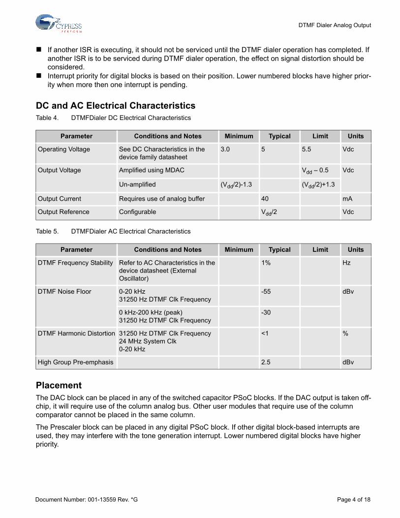
Cypress Semiconductor Corporation • 198 Champion Court • San Jose, CA 95134-1709 • 408-943-2600 Document Number: 001-13559 Rev. *G Revised May 21, 2014 DTMF Dialer Analog Output Datasheet DTMFDialer V 1.5 001-13559 Rev. *G DTMF Dialer Analog Output Copyright © 2003-2014 Cypress Semiconductor Corporation. All Rights Reserved. For one or more fully configured, functional example projects that use this user module go to www.cypress.com/psocexampleprojects. Features and Overview Flexible clocking options Analog output Runs in background to allow system control while dialing (configuration option) Runs in foreground to minimize use of RAM (configuration option) Tones can be output continuously under program control Automatically adds configured tone spacing to all output tones Tone duration can be configured Output capable of -1.7 dBm un-amplified into 600 ohm load, and up to +3.1 dBm amplified drive Output driver capable of driving 32 ohm load at 5 Vrms The DTMFDialer User Module is a Dual Tone Multiple Frequency signal generator. It provides a 6-bit, 2.6 volt full-scale analog output, centered around AGND. The output is a pair of simultaneously generated table sinusoids (tones) that are updated at a user-selectable update frequency. Selection of the update frequency causes a trade-off between CPU loading and signal distortion. Output tone generation is done in an interrupt routine to minimize sample skew and related distortion. Configuration options provide the ability to make design trade-off between RAM consumption and other operational features. Figure 1. DTMFDialer Block Diagram Resources PSoC ® Blocks API Memory (Bytes) Pins (per External I/O) Digital Analog CT Analog SC Flash RAM CY8C29/27/24/xxx, CY8C23x33, CY8CLED04/08/16, CY8CLED0xD, CY8CLED0xG, CY8C28x45, CY8CPLC20, CY8CLED16P01, CY8C28x43, CY8C28x52 Background 1 0 1 758 16 1 for DAC Foreground 1 0 1 753 2 Analog Output
-
Upload
khangminh22 -
Category
Documents
-
view
2 -
download
0
Transcript of DTMF Dialer Analog Output Datasheet DTMFDialer V 1.5
DTMF Dialer Analog Output Datasheet DTMFDialer V 1.5001-13559 Rev. *GDTMF Dialer Analog Output
Copyright © 2003-2014 Cypress Semiconductor Corporation. All Rights Reserved.
For one or more fully configured, functional example projects that use this user module go to www.cypress.com/psocexampleprojects.
Features and Overview Flexible clocking optionsAnalog outputRuns in background to allow system control while dialing (configuration option)Runs in foreground to minimize use of RAM (configuration option)Tones can be output continuously under program controlAutomatically adds configured tone spacing to all output tonesTone duration can be configuredOutput capable of -1.7 dBm un-amplified into 600 ohm load, and up to +3.1 dBm amplified driveOutput driver capable of driving 32 ohm load at 5 Vrms
The DTMFDialer User Module is a Dual Tone Multiple Frequency signal generator. It provides a 6-bit, 2.6 volt full-scale analog output, centered around AGND. The output is a pair of simultaneously generated table sinusoids (tones) that are updated at a user-selectable update frequency. Selection of the update frequency causes a trade-off between CPU loading and signal distortion. Output tone generation is done in an interrupt routine to minimize sample skew and related distortion. Configuration options provide the ability to make design trade-off between RAM consumption and other operational features.Figure 1. DTMFDialer Block Diagram
Resources
PSoC® Blocks API Memory (Bytes)Pins (per
External I/O)Digital Analog CT Analog SC Flash RAM
CY8C29/27/24/xxx, CY8C23x33, CY8CLED04/08/16, CY8CLED0xD, CY8CLED0xG, CY8C28x45, CY8CPLC20, CY8CLED16P01, CY8C28x43, CY8C28x52
Background 1 0 1 758 16 1 for DAC
Foreground 1 0 1 753 2 Analog Output
Cypress Semiconductor Corporation • 198 Champion Court • San Jose, CA 95134-1709 • 408-943-2600Document Number: 001-13559 Rev. *G Revised May 21, 2014

DTMF Dialer Analog Output
Functional Description The DTMFDialer User Module is formed from one analog switched cap PSoC™ block and one digital PSoC block. Figure 2. Simplified Schematic of the DTMFDialer
The analog block is configured as a 6-bit DAC. The digital block is used to scale the control clock and generate an interrupt at the update frequency. The update frequency corresponds to the frequency of the DTMF Clk interrupt. During the interrupt, the DAC is updated with the next value of the tone pair. The pair of tones generated for each of the tones is show in the following table. Table 1. Tone DTMF Matrix
The rows of the matrix shown in the table above represent the low frequencies, while the columns represent the high frequencies. For example, the digit 7 will be the combination of a low tone of 852 Hz
fr /fc 1209 Hz 1336 Hz 1477 Hz 1633 Hz
697 Hz 1 2 3 A a
770 Hz 4 5 6 B b
852 Hz 7 8 9 C c
941 Hz * 0 # D d
Document Number: 001-13559 Rev. *G Page 2 of 18

DTMF Dialer Analog Output
and a high tone of 1209 Hz. The two frequencies are combined to make a continuous time DTMF signal using the following equation, where fu is the update frequency.
Equation 1
The ITU-T DTMF recommendation is that, when encoding DTMF signals, the frequency should be within 1.5% of that stated and, when decoding, any signals out of tolerance by more than 3.5% should be ignored. When encoding, the duration of each tone should be at least 40 ms, with a signal interrupt to follow of at least 10 ms. The DTMF tone energy should exceed the levels of any other frequencies present by at least 30 dB. A summary of this is stated in the following table.Table 2. ITU-T DTMF Recommendations
A requirement that the frequency tolerance be less than 1.5% means that the control clock is one of the following:
CPU_32_ kHz using the external crystal.Another system clock with the PLL enabled.An external clock with the required accuracy brought in on a global in pin.
The input interface to the dialer is done with a string of ASCII characters. Each character defines an action. The possible actions are listed inthe following table. Table 3. Character Action Definitions
The default pause for a comma is 900 ms. Changing the constant iNoToneLength in DTMFDialer.inc alters the default value.
DAC data updates are interrupt driven to minimize signal distortion. The interrupt is based on the terminal count of the digital block associated with this user module. Two points to consider, since distortion is dependent on an ISR, are as follows.
Frequency Tolerance <= 1.5%
Signal Duration >= 40 ms
Signal Interrupt >= 10 ms
Signal Distortion <= 3%
Character Action
0 1 2 3 4 5 6 7 8 9 * # A a B b C c D d Output the appropriate tone pair for selected time period. Automatically adds inter-tone spacing.
, (comma) 900 ms tone space.
\0 (null) End of phone number; dialing is finished.
All other characters Ignore.
Document Number: 001-13559 Rev. *G Page 3 of 18
DTMF Dialer Analog Output
If another ISR is executing, it should not be serviced until the DTMF dialer operation has completed. If another ISR is to be serviced during DTMF dialer operation, the effect on signal distortion should be considered.Interrupt priority for digital blocks is based on their position. Lower numbered blocks have higher prior-ity when more then one interrupt is pending.
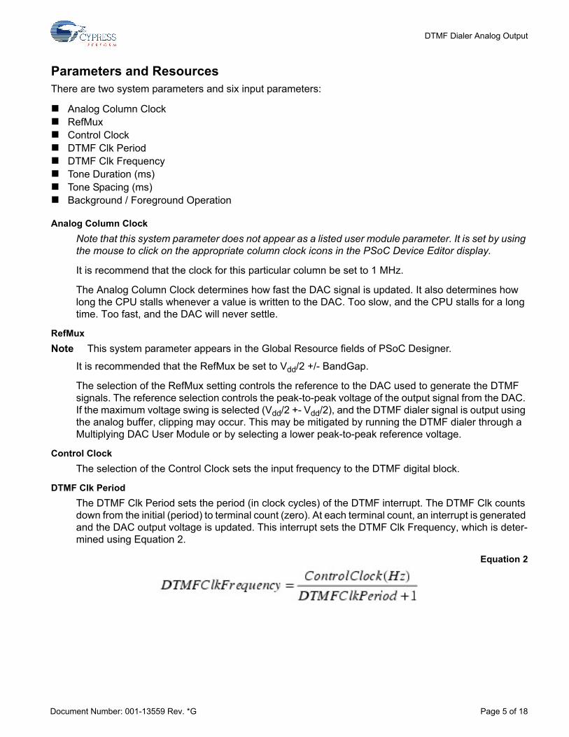
DC and AC Electrical Characteristics Table 4. DTMFDialer DC Electrical Characteristics
Table 5. DTMFDialer AC Electrical Characteristics
Placement The DAC block can be placed in any of the switched capacitor PSoC blocks. If the DAC output is taken off-chip, it will require use of the column analog bus. Other user modules that require use of the column comparator cannot be placed in the same column.
The Prescaler block can be placed in any digital PSoC block. If other digital block-based interrupts are used, they may interfere with the tone generation interrupt. Lower numbered digital blocks have higher priority.
Parameter Conditions and Notes Minimum Typical Limit Units
Operating Voltage See DC Characteristics in the device family datasheet
3.0 5 5.5 Vdc
Output Voltage Amplified using MDAC Vdd – 0.5 Vdc
Un-amplified (Vdd/2)-1.3 (Vdd/2)+1.3
Output Current Requires use of analog buffer 40 mA
Output Reference Configurable Vdd/2 Vdc
Parameter Conditions and Notes Minimum Typical Limit Units
DTMF Frequency Stability Refer to AC Characteristics in the device datasheet (External Oscillator)
1% Hz
DTMF Noise Floor 0-20 kHz31250 Hz DTMF Clk Frequency
-55 dBv
0 kHz-200 kHz (peak)31250 Hz DTMF Clk Frequency
-30
DTMF Harmonic Distortion 31250 Hz DTMF Clk Frequency24 MHz System Clk0-20 kHz
<1 %
High Group Pre-emphasis 2.5 dBv
Document Number: 001-13559 Rev. *G Page 4 of 18
DTMF Dialer Analog Output
Parameters and Resources There are two system parameters and six input parameters:
Analog Column ClockRefMuxControl ClockDTMF Clk PeriodDTMF Clk FrequencyTone Duration (ms)Tone Spacing (ms)Background / Foreground Operation
Analog Column ClockNote that this system parameter does not appear as a listed user module parameter. It is set by using the mouse to click on the appropriate column clock icons in the PSoC Device Editor display.
It is recommend that the clock for this particular column be set to 1 MHz.
The Analog Column Clock determines how fast the DAC signal is updated. It also determines how long the CPU stalls whenever a value is written to the DAC. Too slow, and the CPU stalls for a long time. Too fast, and the DAC will never settle.
RefMuxNote This system parameter appears in the Global Resource fields of PSoC Designer.
It is recommended that the RefMux be set to Vdd/2 +/- BandGap.
The selection of the RefMux setting controls the reference to the DAC used to generate the DTMF signals. The reference selection controls the peak-to-peak voltage of the output signal from the DAC. If the maximum voltage swing is selected (Vdd/2 +- Vdd/2), and the DTMF dialer signal is output using the analog buffer, clipping may occur. This may be mitigated by running the DTMF dialer through a Multiplying DAC User Module or by selecting a lower peak-to-peak reference voltage.
Control ClockThe selection of the Control Clock sets the input frequency to the DTMF digital block.
DTMF Clk PeriodThe DTMF Clk Period sets the period (in clock cycles) of the DTMF interrupt. The DTMF Clk counts down from the initial (period) to terminal count (zero). At each terminal count, an interrupt is generated and the DAC output voltage is updated. This interrupt sets the DTMF Clk Frequency, which is deter-mined using Equation 2.
Equation 2
Document Number: 001-13559 Rev. *G Page 5 of 18
DTMF Dialer Analog Output
For a Control Clock of 4 MHz and the DTMF Clk Period set to 124, the update frequency is calculated using Equation 3.
Equation 3
Given the control clock is 4 MHz and the DTMF Clk frequency is 32 kHz, Equation 4calculates the DTMF Clk Period.
Equation 4
DTMF Clk FrequencyThe equation to calculate the DTMF Clk Frequency value is shown above. The value must be entered as a parameter. The DTMF Clk Frequency impacts the system in two ways:
CPU loadingSignal distortion
CPU loading and signal distortion are inversely related. Increasing the update frequency increases the CPU loading, but decreases the signal distortion. Lowering the update frequency decreases the CPU load, but increases the signal distortion.
CPU LoadingWhen operating the DTMF dialer in background mode, each update takes 244 CPU cycles and one CPU stall. The CPU loading is calculated using Equation 5.
Equation 5
Document Number: 001-13559 Rev. *G Page 6 of 18
DTMF Dialer Analog Output
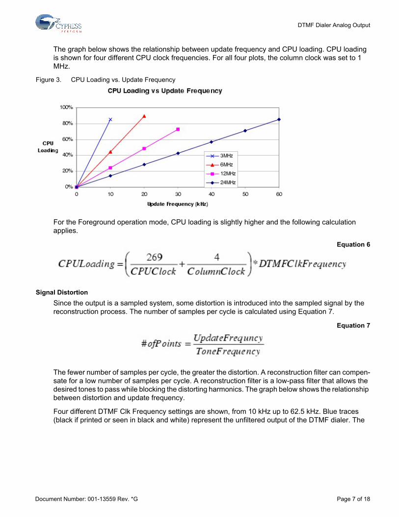
The graph below shows the relationship between update frequency and CPU loading. CPU loading is shown for four different CPU clock frequencies. For all four plots, the column clock was set to 1 MHz.
Figure 3. CPU Loading vs. Update Frequency
For the Foreground operation mode, CPU loading is slightly higher and the following calculation applies.
Equation 6
Signal DistortionSince the output is a sampled system, some distortion is introduced into the sampled signal by the reconstruction process. The number of samples per cycle is calculated using Equation 7.
Equation 7
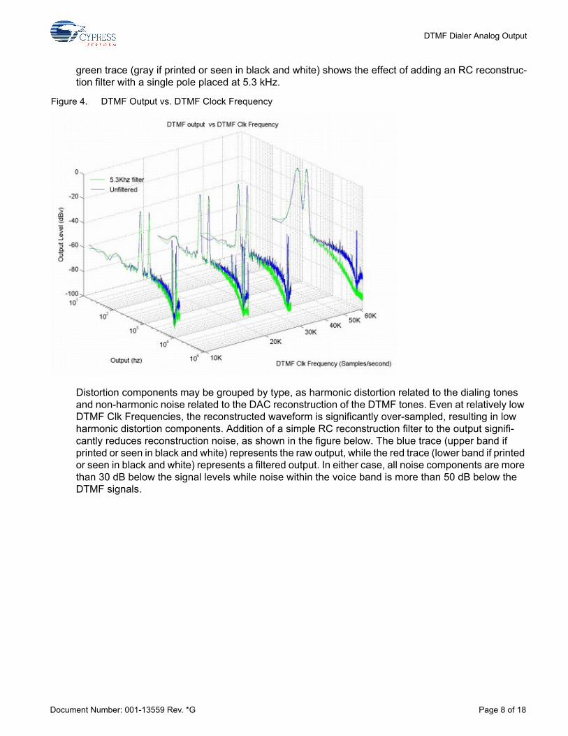
The fewer number of samples per cycle, the greater the distortion. A reconstruction filter can compen-sate for a low number of samples per cycle. A reconstruction filter is a low-pass filter that allows the desired tones to pass while blocking the distorting harmonics. The graph below shows the relationship between distortion and update frequency.
Four different DTMF Clk Frequency settings are shown, from 10 kHz up to 62.5 kHz. Blue traces (black if printed or seen in black and white) represent the unfiltered output of the DTMF dialer. The
Document Number: 001-13559 Rev. *G Page 7 of 18
DTMF Dialer Analog Output
green trace (gray if printed or seen in black and white) shows the effect of adding an RC reconstruc-tion filter with a single pole placed at 5.3 kHz.
Figure 4. DTMF Output vs. DTMF Clock Frequency
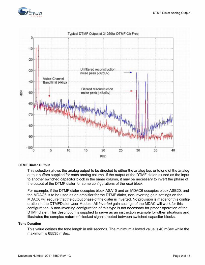
Distortion components may be grouped by type, as harmonic distortion related to the dialing tones and non-harmonic noise related to the DAC reconstruction of the DTMF tones. Even at relatively low DTMF Clk Frequencies, the reconstructed waveform is significantly over-sampled, resulting in low harmonic distortion components. Addition of a simple RC reconstruction filter to the output signifi-cantly reduces reconstruction noise, as shown in the figure below. The blue trace (upper band if printed or seen in black and white) represents the raw output, while the red trace (lower band if printed or seen in black and white) represents a filtered output. In either case, all noise components are more than 30 dB below the signal levels while noise within the voice band is more than 50 dB below the DTMF signals.
Document Number: 001-13559 Rev. *G Page 8 of 18
DTMF Dialer Analog Output
DTMF Dialer OutputThis selection allows the analog output to be directed to either the analog bus or to one of the analog output buffers supplied for each analog column. If the output of the DTMF dialer is used as the input to another switched capacitor block in the same column, it may be necessary to invert the phase of the output of the DTMF dialer for some configurations of the next block.
For example, if the DTMF dialer occupies block ASA10 and an MDAC6 occupies block ASB20, and the MDAC6 is to be used as an amplifier for the DTMF dialer, non-inverting gain settings on the MDAC6 will require that the output phase of the dialer is inverted. No provision is made for this config-uration in the DTMFDialer User Module. All inverted gain settings of the MDAC will work for this configuration. A non-inverting configuration of this type is not necessary for proper operation of the DTMF dialer. This description is supplied to serve as an instruction example for other situations and illustrates the complex nature of clocked signals routed between switched capacitor blocks.
Tone DurationThis value defines the tone length in milliseconds. The minimum allowed value is 40 mSec while the maximum is 65535 mSec.
Document Number: 001-13559 Rev. *G Page 9 of 18

DTMF Dialer Analog Output
Tone SpacingThis value defines the inter-tone spacing in milliseconds. The minimum allowed value is 10 ms, while the maximum is 65535 ms.
Note Internally, Tone Duration and Tone Spacing are implemented as software-timing loops. A 16-bit value is decremented each time the interrupt is entered. Given a fixed interrupt frequency, absolute time is calculated at compile time as a constant 32-bit value. Large values of DTMF Clk Frequency and Tone Spacing or Tone Duration may result in overflow conditions when the 32-bit compiler internal calculation is applied to the 16-bit constant. The product [Tone Duration x DTMF Clk Freq] or [Tone Spacing x DTMF Clk Freq] must be less than 65535 x 1000 or the maximum value of the variable used to calculate the duration of the tone (space) will be exceeded.
Background/Foreground OperationTwo selections are available for creating APIs: BACKGROUND (default) and FOREGROUND.
If Background is selected, all DTMFDialer processing and computation are attached to the ISR (Inter-rupt Service Routine) triggered by the DTMF Clk. This means that as soon as a phone number is passed to the Background algorithm, the function returns and other processing can take place while the phone number is being dialed. Background mode supports the DialDigit() function, which will begin generating the requested tone until another DialDigit() function call either terminates it or supplies a new tone to dial. An example of this would be generating a tone while a telephone key is pressed, stopping upon release of the key. A phone number can be submitted to the background process for dialing, while the foreground process repeatedly calls the bReadStatus() function to deter-mine when the number has been completely dialed. Attaching all functions to the DTMF Clk ISR requires the use of 16 bytes of globally-defined RAM.
If Foreground mode is selected, most DTMF dialer functions are conducted outside of the DTMF Clk ISR. Only the actual tone generation is done within the ISR. The DialFromRam/Rom() function for this instance will return only after the phone number has been completely dialed. When the Foreground mode is selected, the DialDigit() function is disabled. The main advantage of using the Foreground option is that only two bytes of globally-defined RAM are used. This offers advantages if maximizing RAM memory space is critical or if dynamic re-configuration is used, since global variables assigned within user modules may be difficult to re-use, even when the module in question is unloaded.
Interrupt Generation ControlThere is an additional parameter that becomes available when the Enable interrupt generation control check box in PSoC Designer is checked. This is available under Project > Settings > Chip Editor. Interrupt Generation Control is important when multiple overlays are used with interrupts shared by multiple user modules across overlays:
IntDispatchModeThe IntDispatchMode parameter is used to specify how an interrupt request is handled for interrupts shared by multiple user modules existing in the same block but in different overlays. Selecting “ActiveStatus" causes firmware to test which overlay is active before servicing the shared interrupt request. This test occurs every time the shared interrupt is requested. This adds latency and also produces a nondeterministic procedure of servicing shared interrupt requests, but does not require any RAM. Selecting “OffsetPreCalc" causes firmware to calculate the source of a shared interrupt request only when an overlay is initially loaded. This calculation decreases interrupt latency and produces a deterministic procedure for servicing shared interrupt requests, but at the expense of a byte of RAM.
Document Number: 001-13559 Rev. *G Page 10 of 18
DTMF Dialer Analog Output
Application Programming Interface The Application Programming Interface (API) routines are provided as part of the user module to allow the designer to deal with the module at a higher level. This section specifies the interface to each function together with related constants provided by the “include" files.Note
In this, as in all user module APIs, the values of the A and X register may be altered by calling an API function. It is the responsibility of the calling function to preserve the values of A and X prior to the call if those values are required after the call. This “registers are volatile" policy was selected for efficiency reasons and has been in force since version 1.0 of PSoC Designer. The C compiler automatically takes care of this requirement. Assembly language programmers must ensure their code observes the policy, too. Though some user module API function may leave A and X unchanged, there is no guarantee they will do so in the future.
For Large Memory Model devices, it is also the caller's responsibility to perserve any value in the CUR_PP, IDX_PP, MVR_PP, and MVW_PP registers. Even though some of these registers may not be modified now, there is no guarantee that will remain the case in future releases.
Entry points are to initialize the Dialer, start Dialer sampling, and stop the Dialer.
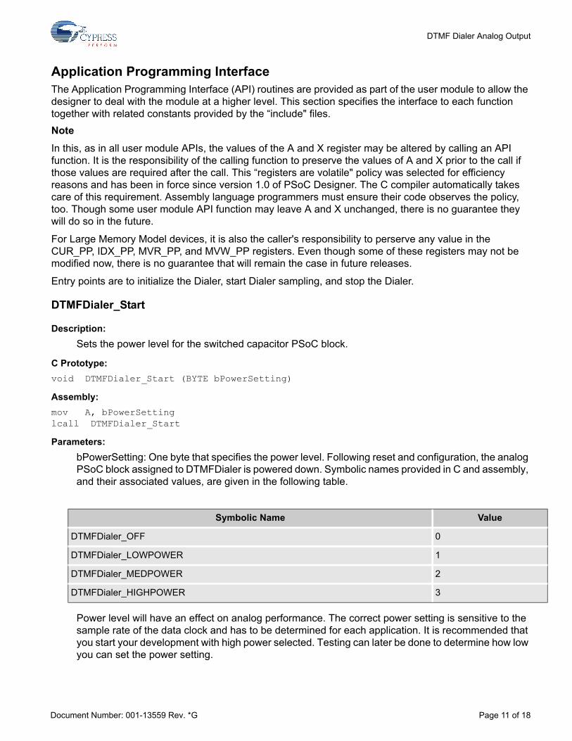
DTMFDialer_Start
Description: Sets the power level for the switched capacitor PSoC block.
C Prototype:void DTMFDialer_Start (BYTE bPowerSetting)
Assembly:mov A, bPowerSettinglcall DTMFDialer_Start
Parameters:bPowerSetting: One byte that specifies the power level. Following reset and configuration, the analog PSoC block assigned to DTMFDialer is powered down. Symbolic names provided in C and assembly, and their associated values, are given in the following table.
Power level will have an effect on analog performance. The correct power setting is sensitive to the sample rate of the data clock and has to be determined for each application. It is recommended that you start your development with high power selected. Testing can later be done to determine how low you can set the power setting.
Symbolic Name Value
DTMFDialer_OFF 0
DTMFDialer_LOWPOWER 1
DTMFDialer_MEDPOWER 2
DTMFDialer_HIGHPOWER 3
Document Number: 001-13559 Rev. *G Page 11 of 18

DTMF Dialer Analog Output
Return Value: None
Side Effects: The A and X registers may be altered by this function.
DTMFDialer_SetPower
Description: Sets the power level for the switched capacitor PSoC block.
C Prototype:void DTMFDialer_SetPower (BYTE bPowerSetting)
Assembly:mov A, bPowerSettinglcall DTMFDialer_SetPower
Parameters:bPowerSetting: Same as the bPowerSetting parameter used for the "Start" entry point. Allows the user to change the power level while operating the DTMFDialer.
Return Value: None
Side Effects: The A and X registers may be altered by this function.
DTMFDialer_StartSamples
Description: Enables the Prescaler counter, so that the DAC output initializes. The global interrupt must be enabled for the DTMFDialer to work.
C Prototype:void DTMFDialer_StartSamples (void)
Assembly:lcall DTMFDialer_StartSamples
Parameters: None
Return Value: None
Side Effects: The A and X registers may be altered by this function.
Document Number: 001-13559 Rev. *G Page 12 of 18
DTMF Dialer Analog Output
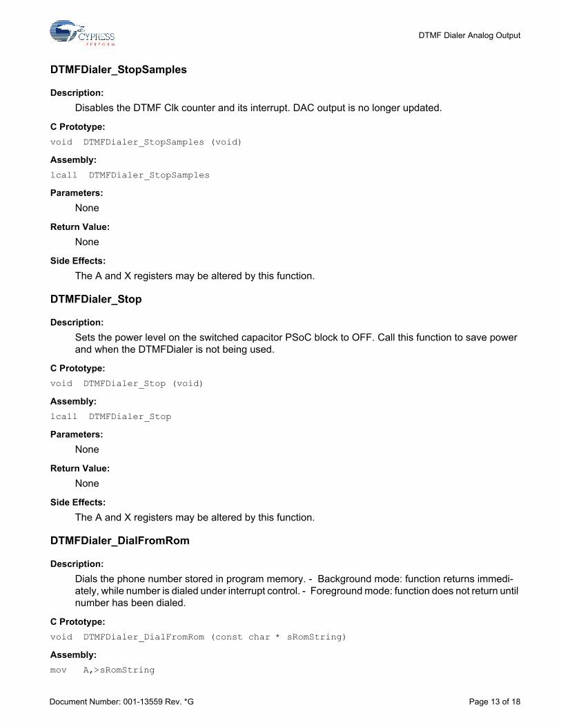
DTMFDialer_StopSamples
Description: Disables the DTMF Clk counter and its interrupt. DAC output is no longer updated.
C Prototype:void DTMFDialer_StopSamples (void)
Assembly:lcall DTMFDialer_StopSamples
Parameters: None
Return Value: None
Side Effects: The A and X registers may be altered by this function.
DTMFDialer_Stop
Description:Sets the power level on the switched capacitor PSoC block to OFF. Call this function to save power and when the DTMFDialer is not being used.
C Prototype:void DTMFDialer_Stop (void)
Assembly:lcall DTMFDialer_Stop
Parameters: None
Return Value: None
Side Effects: The A and X registers may be altered by this function.
DTMFDialer_DialFromRom
Description: Dials the phone number stored in program memory. - Background mode: function returns immedi-ately, while number is dialed under interrupt control. - Foreground mode: function does not return until number has been dialed.
C Prototype:void DTMFDialer_DialFromRom (const char * sRomString)
Assembly:mov A,>sRomString
Document Number: 001-13559 Rev. *G Page 13 of 18
DTMF Dialer Analog Output
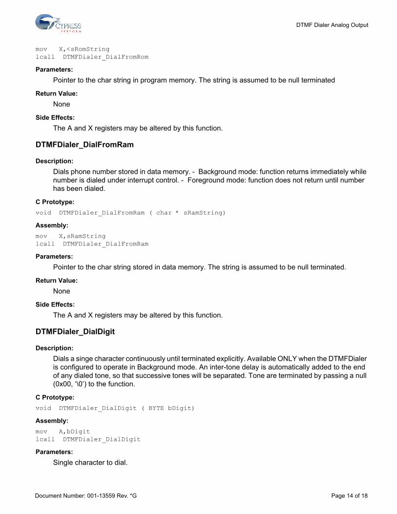
mov X,<sRomStringlcall DTMFDialer_DialFromRom
Parameters: Pointer to the char string in program memory. The string is assumed to be null terminated
Return Value: None
Side Effects: The A and X registers may be altered by this function.
DTMFDialer_DialFromRam
Description: Dials phone number stored in data memory. - Background mode: function returns immediately while number is dialed under interrupt control. - Foreground mode: function does not return until number has been dialed.
C Prototype:void DTMFDialer_DialFromRam ( char * sRamString)
Assembly:mov X,sRamStringlcall DTMFDialer_DialFromRam
Parameters: Pointer to the char string stored in data memory. The string is assumed to be null terminated.
Return Value: None
Side Effects: The A and X registers may be altered by this function.
DTMFDialer_DialDigit
Description: Dials a singe character continuously until terminated explicitly. Available ONLY when the DTMFDialer is configured to operate in Background mode. An inter-tone delay is automatically added to the end of any dialed tone, so that successive tones will be separated. Tone are terminated by passing a null (0x00, ‘\0’) to the function.
C Prototype:void DTMFDialer_DialDigit ( BYTE bDigit)
Assembly:mov A,bDigitlcall DTMFDialer_DialDigit
Parameters: Single character to dial.
Document Number: 001-13559 Rev. *G Page 14 of 18
DTMF Dialer Analog Output
Return Value: None
Side Effects: The A and X registers may be altered by this function.
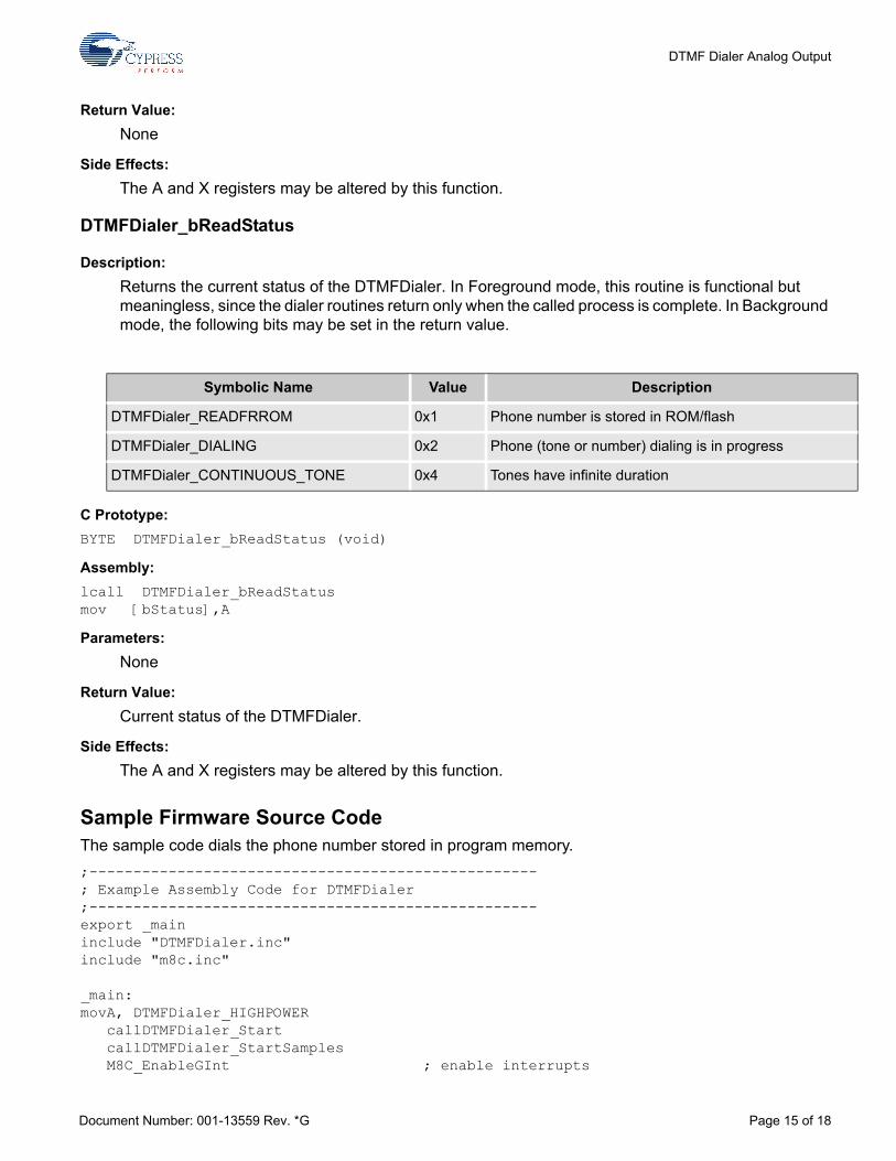
DTMFDialer_bReadStatus
Description: Returns the current status of the DTMFDialer. In Foreground mode, this routine is functional but meaningless, since the dialer routines return only when the called process is complete. In Background mode, the following bits may be set in the return value.
C Prototype:BYTE DTMFDialer_bReadStatus (void)
Assembly:lcall DTMFDialer_bReadStatusmov [bStatus],A
Parameters: None
Return Value: Current status of the DTMFDialer.
Side Effects: The A and X registers may be altered by this function.
Sample Firmware Source Code The sample code dials the phone number stored in program memory. ;---------------------------------------------------; Example Assembly Code for DTMFDialer;---------------------------------------------------export _maininclude "DTMFDialer.inc"include "m8c.inc"
_main:movA, DTMFDialer_HIGHPOWER callDTMFDialer_Start callDTMFDialer_StartSamples M8C_EnableGInt ; enable interrupts
Symbolic Name Value Description
DTMFDialer_READFRROM 0x1 Phone number is stored in ROM/flash
DTMFDialer_DIALING 0x2 Phone (tone or number) dialing is in progress
DTMFDialer_CONTINUOUS_TONE 0x4 Tones have infinite duration
Document Number: 001-13559 Rev. *G Page 15 of 18

DTMF Dialer Analog Output
mov A, >pcPhoneNumber mov X, <pcPhoneNumber callDTMFDialer_DialFromRomloop: jmp loop ; The rest of the program .LITERALpcPhoneNumber: ds "9,5551212" db 00h ; needed as a string delimiter.ENDLITERAL
The same code is written in C as follows. //------------------------------------------------------------------------// Example C Code for DTMFDialer User Module//------------------------------------------------------------------------#include "DTMFDialer.h"#include "m8c.h"void main(void){ const char * pcPhoneNumber = "9,5551212"; M8C_EnableGInt; DTMFDialer_Start(DTMFDialer_HIGHPOWER); DTMFDialer_StartSamples(); DTMFDialer_DialFromRom(pcPhoneNumber); while(1); //rest of program}
Configuration Registers The DAC is a switched capacitor PSoC block. It is configured to be a 6-bit analog DAC.Table 6. Block DAC: Register CR0
ACap is used by the DTMF_Clk interrupt to set the output value of the DAC.Table 7. Block DAC: Register CR1
Table 8. Block DAC: Register CR2
ABus is a parameter set by the user to bring the DAC output off-chip.Table 9. Block DAC: Register CR3
Bit 7 6 5 4 3 2 1 0
Value 1 0 0 ACap
Bit 7 6 5 4 3 2 1 0
Value 1 0 0 0 0 0 0 0
Bit 7 6 5 4 3 2 1 0
Value ABus 0 1 0 0 0 0 0
Bit 7 6 5 4 3 2 1 0
Value 0 0 1 1 0 0 0 0
Document Number: 001-13559 Rev. *G Page 16 of 18
DTMF Dialer Analog Output
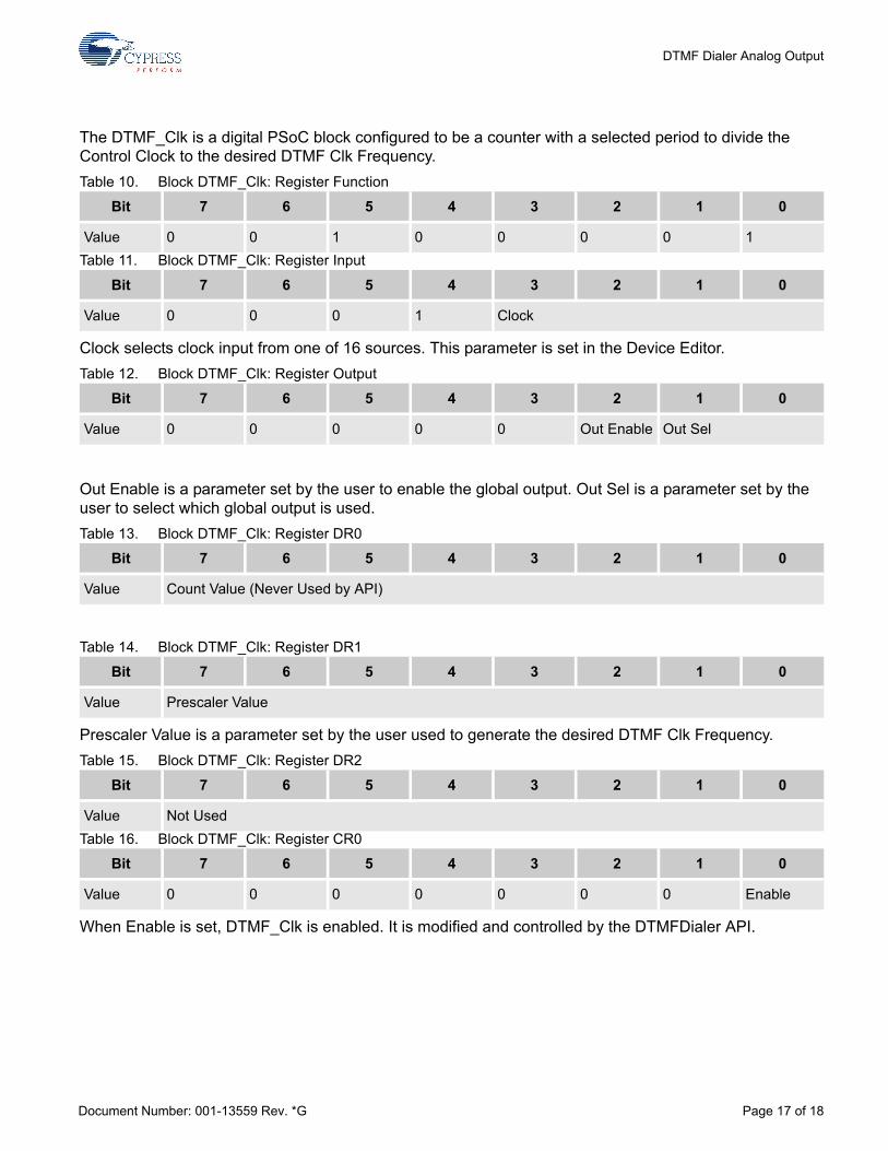
The DTMF_Clk is a digital PSoC block configured to be a counter with a selected period to divide the Control Clock to the desired DTMF Clk Frequency.Table 10. Block DTMF_Clk: Register Function
Table 11. Block DTMF_Clk: Register Input
Clock selects clock input from one of 16 sources. This parameter is set in the Device Editor.Table 12. Block DTMF_Clk: Register Output
Out Enable is a parameter set by the user to enable the global output. Out Sel is a parameter set by the user to select which global output is used.Table 13. Block DTMF_Clk: Register DR0
Table 14. Block DTMF_Clk: Register DR1
Prescaler Value is a parameter set by the user used to generate the desired DTMF Clk Frequency.Table 15. Block DTMF_Clk: Register DR2
Table 16. Block DTMF_Clk: Register CR0
When Enable is set, DTMF_Clk is enabled. It is modified and controlled by the DTMFDialer API.
Bit 7 6 5 4 3 2 1 0
Value 0 0 1 0 0 0 0 1
Bit 7 6 5 4 3 2 1 0
Value 0 0 0 1 Clock
Bit 7 6 5 4 3 2 1 0
Value 0 0 0 0 0 Out Enable Out Sel
Bit 7 6 5 4 3 2 1 0
Value Count Value (Never Used by API)
Bit 7 6 5 4 3 2 1 0
Value Prescaler Value
Bit 7 6 5 4 3 2 1 0
Value Not Used
Bit 7 6 5 4 3 2 1 0
Value 0 0 0 0 0 0 0 Enable
Document Number: 001-13559 Rev. *G Page 17 of 18
DTMF Dialer Analog Output
Version History
Note PSoC Designer 5.1 introduces a Version History in all user module datasheets. This section docu-ments high level descriptions of the differences between the current and previous user module ver-sions.
Version Originator Description
1.5 DHA Added Version History
Document Number: 001-13559 Rev. *G Revised May 21, 2014 Page 18 of 18Copyright © 2003-2014 Cypress Semiconductor Corporation. The information contained herein is subject to change without notice. Cypress Semiconductor Corporation assumes no responsibilityfor the use of any circuitry other than circuitry embodied in a Cypress product. Nor does it convey or imply any license under patent or other rights. Cypress products are not warranted nor intendedto be used for medical, life support, life saving, critical control or safety applications, unless pursuant to an express written agreement with Cypress. Furthermore, Cypress does not authorize itsproducts for use as critical components in life-support systems where a malfunction or failure may reasonably be expected to result in significant injury to the user. The inclusion of Cypress productsin life-support systems application implies that the manufacturer assumes all risk of such use and in doing so indemnifies Cypress against all charges.
PSoC Designer™ and Programmable System-on-Chip™ are trademarks and PSoC® is a registered trademark of Cypress Semiconductor Corp. All other trademarks or registered trademarksreferenced herein are property of the respective corporations.
Any Source Code (software and/or firmware) is owned by Cypress Semiconductor Corporation (Cypress) and is protected by and subject to worldwide patent protection (United States and foreign),United States copyright laws and international treaty provisions. Cypress hereby grants to licensee a personal, non-exclusive, non-transferable license to copy, use, modify, create derivative worksof, and compile the Cypress Source Code and derivative works for the sole purpose of creating custom software and or firmware in support of licensee product to be used only in conjunction witha Cypress integrated circuit as specified in the applicable agreement. Any reproduction, modification, translation, compilation, or representation of this Source Code except as specified above isprohibited without the express written permission of Cypress.
Disclaimer: CYPRESS MAKES NO WARRANTY OF ANY KIND, EXPRESS OR IMPLIED, WITH REGARD TO THIS MATERIAL, INCLUDING, BUT NOT LIMITED TO, THE IMPLIED WARRANTIESOF MERCHANTABILITY AND FITNESS FOR A PARTICULAR PURPOSE. Cypress reserves the right to make changes without further notice to the materials described herein. Cypress does notassume any liability arising out of the application or use of any product or circuit described herein. Cypress does not authorize its products for use as critical components in life-support systemswhere a malfunction or failure may reasonably be expected to result in significant injury to the user. The inclusion of Cypress' product in a life-support systems application implies that the manufacturerassumes all risk of such use and in doing so indemnifies Cypress against all charges.
Use may be limited by and subject to the applicable Cypress software license agreement.