Double Corrosion Protection (DCP) - Minova
7
DOUBLE CORROSION PROTECTION WWW.MINOVAGLOBAL.COM MICROPILES | SOIL NAILS | GROUND ANCHORS
-
Upload
khangminh22 -
Category
Documents
-
view
1 -
download
0
Transcript of Double Corrosion Protection (DCP) - Minova
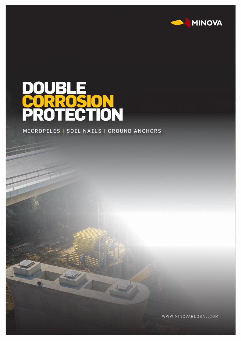
DOUBLE CORROSION PROTECTION
W W W. M I N O VA G L O B A L . C O M
MIC R O P IL E S | S OIL N A IL S | G R O U N D A N C H O R S

Micropiles, Soil & Rock Nails and Ground Anchors with double corrosion protection provide enhanced support, even in the most demanding conditions.
WHAT IS DCP? Double Corrosion Protection (DCP) is a factory pre-grouted encapsulation of our steel tendons within a corrugated plastic sheath. Using DCP ensures durability and consistent long-term performance. We offer the Minova DCP ATB threadbar system, which is recognised for performance and meets three internationally recognised design standards*.
HOW CAN WE HELP?
Our solutions are ideal for complicated engineering structures in need of immediate ground control with an enhanced lifespan. If an application has a service life greater than 24 months it is generally considered ‘permanent’ and should always have some type of corrosion protection incorporated into its design. The level of corrosion protection required is primarily dependent on the required service life and the aggressivity of the environment.
DESIGNED FOR ENHANCED PERFORMANCE
OUR ATB THREAD BAR SYSTEM CAN MEET THE MOST CHALLENGING CONDITIONS AND REQUIRED SERVICE LIFE
*EN1537:2013, EN14199:2015 and EN14490:2010 ”
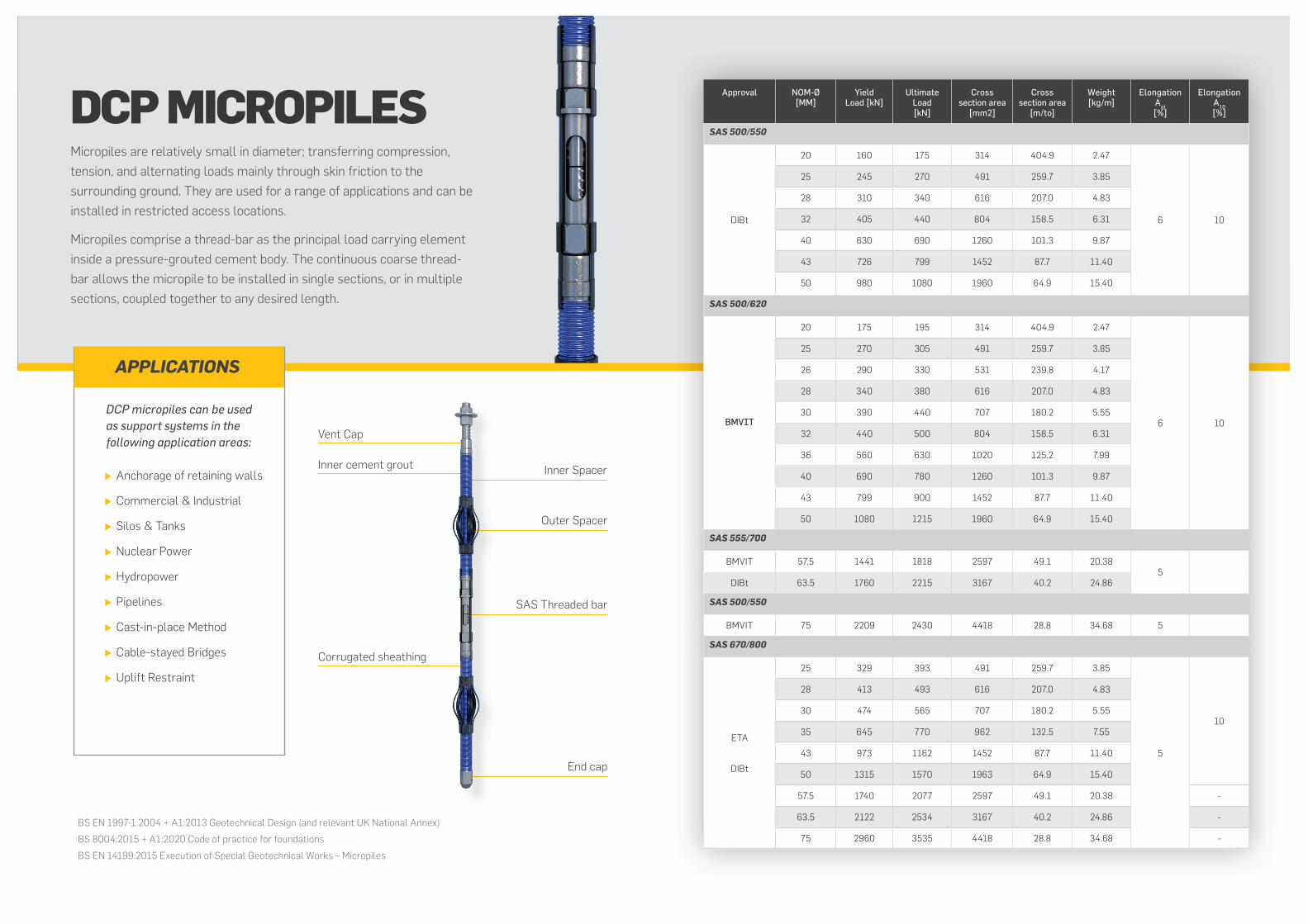
DCP MICROPILESMicropiles are relatively small in diameter; transferring compression, tension, and alternating loads mainly through skin friction to the surrounding ground. They are used for a range of applications and can be installed in restricted access locations.
Micropiles comprise a thread-bar as the principal load carrying element inside a pressure-grouted cement body. The continuous coarse thread-bar allows the micropile to be installed in single sections, or in multiple sections, coupled together to any desired length.
BS EN 1997-1:2004 + A1:2013 Geotechnical Design (and relevant UK National Annex)
BS 8004:2015 + A1:2020 Code of practice for foundations
BS EN 14199:2015 Execution of Special Geotechnical Works – Micropiles
X Anchorage of retaining walls
X Commercial & Industrial
X Silos & Tanks
X Nuclear Power
X Hydropower
X Pipelines
X Cast-in-place Method
X Cable-stayed Bridges
X Uplift Restraint
Vent Cap
Inner cement grout
Corrugated sheathing
Inner Spacer
Outer Spacer
SAS Threaded bar
End cap
Approval NOM-Ø [MM]
Yield Load [kN]
Ultimate Load[kN]
Cross section area
[mm2]
Cross section area
[m/to]
Weight [kg/m]
ElongationAgt [%]
Elongation A10 [%]
SAS 500/550
DIBt
20 160 175 314 404.9 2.47
6 10
25 245 270 491 259.7 3.85
28 310 340 616 207.0 4.83
32 405 440 804 158.5 6.31
40 630 690 1260 101.3 9.87
43 726 799 1452 87.7 11.40
50 980 1080 1960 64.9 15.40
SAS 500/620
BMVIT
20 175 195 314 404.9 2.47
6 10
25 270 305 491 259.7 3.85
26 290 330 531 239.8 4.17
28 340 380 616 207.0 4.83
30 390 440 707 180.2 5.55
32 440 500 804 158.5 6.31
36 560 630 1020 125.2 7.99
40 690 780 1260 101.3 9.87
43 799 900 1452 87.7 11.40
50 1080 1215 1960 64.9 15.40
SAS 555/700
BMVIT 57.5 1441 1818 2597 49.1 20.385
DIBt 63.5 1760 2215 3167 40.2 24.86
SAS 500/550
BMVIT 75 2209 2430 4418 28.8 34.68 5
SAS 670/800
ETA
DIBt
25 329 393 491 259.7 3.85
5
10
28 413 493 616 207.0 4.83
30 474 565 707 180.2 5.55
35 645 770 962 132.5 7.55
43 973 1162 1452 87.7 11.40
50 1315 1570 1963 64.9 15.40
57.5 1740 2077 2597 49.1 20.38 -
63.5 2122 2534 3167 40.2 24.86 -
75 2960 3535 4418 28.8 34.68 -
DCP micropiles can be used as support systems in the following application areas:
APPLICATIONS

DCP SOIL NAIL & ROCK NAILSSoil nailing is a passive system used mainly to stabilise slopes, deep excavations and retaining walls. The reinforcing elements are drilled and grouted in the ground. As a result of the deformation of soil or weathered rock mass, tensile and shear forces act on the reinforcement. These axial tensile loads are transferred by the soil nail to the surrounding soil through shear stresses along the grout-soil interface.
Vent Cap
Inner cement grout Inner Spacer
Outer Spacer
ATB thread bar
End cap
Approval NOM-Ø [MM]
Yield Load [kN]
Ultimate Load[kN]
Cross section area
[mm2]
Cross section area
[m/to]
Weight [kg/m]
ElongationAgt [%]
Elongation A10 [%]
SAS 500/550
DIBt
16 100 110 201 632.9 1.58
6 10
20 160 175 314 404.9 2.47
25 245 270 491 259.7 3.85
28 310 340 616 207.0 4.83
32 405 440 804 158.5 6.31
40 630 690 1260 101.3 9.87
43 726 799 1452 87.7 11.40
50 980 1080 1960 64.9 15.40
SAS 500/620
BMVIT
16 110 125 201 632.9 1.58
6 10
20 175 195 314 404.9 2.47
25 270 305 491 259.7 3.85
26 290 330 531 239.8 4.17
28 340 380 616 207.0 4.83
30 390 440 707 180.2 5.55
32 440 500 804 158.5 6.31
36 560 630 1020 125.2 7.99
40 690 780 1260 101.3 9.87
43 799 900 1452 87.7 11.40
50 1080 1215 1960 64.9 15.40
SAS 555/700
BMVIT 57.5 1441 1818 2597 49.1 20.385
DIBt 63.5 1760 2215 3167 40.2 24.86
SAS 500/550
BMVIT 75 2209 2430 4418 28.8 34.68 5
SAS 670/800
ETA
DIBt
18 170 204 254 500.0 2.00
5
10
22 255 304 380 335.6 2.98
25 329 393 491 259.7 3.85
28 413 493 616 207.0 4.83
30 474 565 707 180.2 5.55
35 645 770 962 132.5 7.55
43 973 1162 1452 87.7 11.40
50 1315 1570 1963 64.9 15.40
57.5 1740 2077 2597 49.1 20.38 -
63.5 2122 2534 3167 40.2 24.86 -
75 2960 3535 4418 28.8 34.68 -
BS 8006-2: 2011 Code of Practice for Strengthened / Reinforced Soils. Part 2: Soil Nail Design
BS EN 14490 : 2010 Execution of Special Geotechnical Works - Soil Nailing
CIRIA C637 2005 Soil Nailing - Best Practice Guidance
X Stabilisation of terraces, existing and new slope faces, deep excavations
X Retaining Walls
X Embankment stabilisation
X Fixation of rock fall mesh
APPLICATIONS

DCP GROUND ANCHORSPrestressed soil and rock anchors are components initiating high forces on tension members into the foundation soil. The prestressing process enables stabilisation with low deformation, by preventing elongations and distortions. The forces are directed from the anchor head, which transmits the load into stable soil layers.
Steel cap
Corrugated sheathing
Inner spacer
Inner cement grout
Plate with steel tube
Outer Spacer
Profile ring
SAS Threaded bar
End cap
Vent cap
Approval NOM-Ø [MM]
Yield Load [kN]
Ultimate Load[kN]
Cross section area
[mm2]
Cross section area
[m/to]
Weight [kg/m]
ElongationAgt [%]
Elongation A10 [%]
SAS 500/550
40 630 690 1260 101.3 9.87
6 1043 726 799 1452 87.7 11.40
50 980 1080 1960 64.9 15.40
SAS 555/700
57.5 1441 1818 2597 49.1 20.385
63.5 1760 2215 3167 40.2 24.86
SAS 670/800
ETA
DIBt
BMVIT
18 170 204 254 500.0 2.00
5
10
22 255 304 380 335.6 2.98
25 329 393 491 259.7 3.85
28 413 493 616 207.0 4.83
30 474 565 707 180.2 5.55
35 645 770 962 132.5 7.55
43 973 1162 1452 87.7 11.40
50 1315 1570 1963 64.9 15.40
57.5 1740 2077 2597 49.1 20.38 -
63.5 2122 2534 3167 40.2 24.86 -
75 2960 3535 4418 28.8 34.68 -
SAS 950/1050
ETA
DIBt
BMVIT
18 230 255 241 510.2 1.96
5 7
26.5 525 580 551 223.2 4.48
32 760 845 804 153.1 6.53
36 960 1070 1020 120.9 8.27
40 1190 1320 1257 97.9 10.21
47 1650 1820 1735 70.9 14.10
SAS 835/1035
57 2155 2671 2581 47.7 20.95
4 765 2780 3447 3331 36.9 27.10
75 3690 4572 4418 27.9 35.90
BS EN 1997-1:2004 + A1:2013 Geotechnical Design (and relevant UK National Annex)
BS 8081:2015 Code of Practice for Grouted Anchors
BS EN 1537:2013 Execution of Special Geotechnical Works - Ground Anchors
X Tie back of deep excavation walls
X Buoyancy security
X Bridge abutments
X Stabilization
X Foundations for cable-stayed bridges
X Slope reinforcement
APPLICATIONS

TENDON
SHEATHING
GROUT
ATB Threadbar: To associated National Standards BS 4449, DIN 488 and DIN 1045. Bar diameters: 20mm - 50mmØ grade 500/550 & 63.5mmØ grade 555/700
ATB+ Threadbar: To associated National Standards BS 4449, DIN 488 and DIN 1045. Bar diameters: 25mm - 75mmØ grade 670/800
PST Threadbar: To associated National Standards BS 4486, DIN 4125 and DIN 4227. Bar diameters : 57mm - 75mmØ grade 835/1035
Bearing plate: Fabricated from steel plate to BS EN10025-1:2004 Grade S275JR.
Anchor nut: Steel forging - Grade St. 50.2.
Internal spacers: Injection moulded high density polyethylene.
Internal spacer cord: Extruded polyethylene.
End caps: Injection moulded low density polyethylene.
Heat shrink sleeves: Cross-linked polyolefin with internal mastic sealant.
Grout tubes: Polypropylene.
Wrap round spacers: Injection moulded polypropylene.
Lantern spacers: Polyvinyl chloride.
Generally PVC corrugated sheath over the entire length of the bar.
Minimum wall thickness: 0.8mm.
Pitch of corrugations: Between 6 and 12 times the wall thickness.
Amplitude: Not less than 3 times the wall thickness.
Cement grout is injected after mixing in a high speed colloidal mixer.
Cement type: Rapid Portland Cement to BS EN 197-1 - CEM I 52.5R.
Grout additive: Tricosol 181 - 1% by weight, to reduce shrinkage and plasticise.
Water cement ratio: water cement ratio - 0.38.
Compressive strength: 40N/mm² at 28 days - tested in accordance with BS EN 12390:2009.
DCP MATERIAL SPECIFICATION
European technical approval: ETA-11/0138, ETA-12/0601, ETA-13/0022 DIBt The Deutsches Institut für Bautechnik. National technical approval /general construction permit for the German market
In Compliance With
EN ISO 1537 : 2013 Execution of Special Geotechnical Works – Ground Anchors
EN ISO 14199 : 2015 Execution of Special Geotechnical Works – Micropiles
EN ISO 14490 : 2010 Execution of Special Geotechnical Works – Soil Nails
APPROVALS - BMVIT AND ETA
ANCILLARIES
ANCHOR HEAD

SECURING PERFORMANCE TOGETHER
+44 1226 280567 | [email protected] Unit 5c, Ashroyd Business Park, Barnsley, South Yorkshire, S74 9SB
CONTACT OUR TEAM