Mamual DCP
48
Salicru Power D.C. Power Supply System User Manual Doc. No. SA-DC-11 Rev. 02
-
Upload
independent -
Category
Documents
-
view
2 -
download
0
Transcript of Mamual DCP
Salicru Power
D.C. Power Supply System
User Manual
Doc. No. SA-DC-11Rev. 02

Table of Contents
1、 SUMMARY..............................................................1
1.1 SYSTEM TYPE EXPLANATION.................................................11.2 SYSTEM CHARACTERIZATION................................................11.3 TECHNOLOGY PARAMETER..................................................1
2、 POWER’SUN-M4.........................................................2
2.1 MAIN FUNCTION.........................................................22.2 MONITOR SYSTEM STRUCTURE................................................22.3 MAIN MONITOR INTERFACE AND EXPLANATION....................................32.4 HOST MONITOR OPERATING INTRODUCTION.......................................3
3、 PM3A MONITOR UNIT...................................................14
3.1 TECHNOLOGY PARAMETERS.................................................143.2 INTERFACE EXPLANATION.................................................143.3 SETTING EXPLANATION...................................................15
4、 PM3D MONITOR UNIT...................................................15
4.1 TECHNOLOGY PARAMETERS.................................................154.2 INTERFACE EXPLANATION..................................................154.3 SETTING EXPLANATION...................................................17
5、 PM3K SWITCH MONITOR UNIT............................................17
5.1 TECHNOLOGY PARAMETERS..................................................175.2 INTERFACE EXPLANATION..................................................175.3 SETTING EXPLANATION...................................................18
6、 K2A20L RECTIFIER....................................................19
6.1 ERROR ALARM..........................................................196.2 INTERFACE DESCRIPTION..................................................196.3 OPERATION FLOW-CHART..................................................216.4 OPERATION MANUAL......................................................21
7、 COMMON FAULT PROCESSING.............................................23
7.1 PM4 COMMON FAULT PROCESSING............................................23

7.2 K2A20 LMODULE COMMON FAULT PROCESSING....................................277.3 AC MONITOR UNIT COMMON FAULT PROCESSING...................................287.4 DC MONITOR UNIT COMMON FAULT PROCESSING...................................307.5 Switch quantity monitor unit common fault processing...............32
D.C. Power Supply System User Manual SA-DC-11 Rev.02
1. Summary(Tóm tắt)
The power system contains rectifier modulule, battery, monitor
unit and some wiring units. The main parts of the system are modules,
it accomplishes N+1 redundant backup, hot-plug and on line repairable.
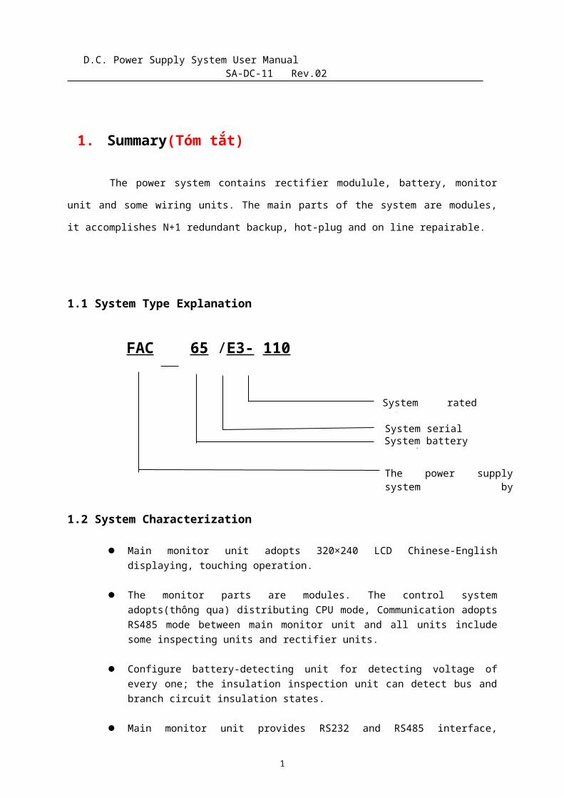
1.1 System Type Explanation
1.2 System Characterization
Main monitor unit adopts 320×240 LCD Chinese-Englishdisplaying, touching operation.
The monitor parts are modules. The control systemadopts(thông qua) distributing CPU mode, Communication adoptsRS485 mode between main monitor unit and all units includesome inspecting units and rectifier units.
Configure battery-detecting unit for detecting voltage ofevery one; the insulation inspection unit can detect bus andbranch circuit insulation states.
Main monitor unit provides RS232 and RS485 interface,
1
FAC 65 /E3- 110
System serialSystem battery capacity
The power supplysystem bymicrocomputer control
System ratedvoltage
D.C. Power Supply System User Manual SA-DC-11 Rev.02
provides three protocols include RTU, CDT and MODBUS, so itcan communicate with auto-system of power station.
1.3 Technology parameter
AC Input: 400V±15%, 50Hz±10% Output Voltage: 90V – 143V Output Current: 60A(Rated) Module Limited Current: 10% - 110% Battery Manage: Auto Machine Window: 320×240 LCD Chinese-English displaying,
touching operation. Communication Interface: Support RS232 and RS485 mode,
Support CDT451-91 and MODBUS communication protocol Cabinet Size: 2260mm×800mm×600mm
2. Power’sun-m4
2.1 Main function
Detect the output current of the rectifier module and errorstate: When there is error, the system will make sound andlight alarm signal and average the load of rectifier moduleagain.
Locally or remotely control the on/off of the rectifiermodule and auto control equalize/floating charge of thebattery.
Locally or remotely set the output voltage and current limitof the module continuously(lien tục).
Monitor DC output voltage and current, the state of MCB, fuseplug state, insulation state and dropping voltage modulestate. When something is wrong, it will make sound and lightalarm.
Monitor battery voltage and charging/discharging current:When AC main terminal voltage begins to drop(khi mà ACcurrent bắt đầu giảm), if it drops to alarm upper limit(nếunó giảm xuống tới giới hạn trên), there will be sound and
2
D.C. Power Supply System User Manual SA-DC-11 Rev.02
light alarm; When the AC main recovers, the system controlsequalize(cân bằng) charging for the battery; If the batteryis in floating charging state too long, the system controlequalize charge for the battery every other time formaintaining it(duy trì nó). (The time is set by users and thedefault value is 720 hours.)
Support detecting batteries. It has over/under-voltage andvoltage difference(chênh lệch điện áp) alarming function forsingle battery and finds the error battery exactly.
Support insulation testing branch circuit of bus bar. Therewill be alarm if the insulating resistance of branch circuitis too low.
Adopt standard communication protocol, RS232/RS485 COM port,support 1200bps、2400bps、4800bps、9600bps baud rate, it iseasy to connected with electric autoimmunization system.Realize four functions such as remote communication, remotemeasure, remote control, and remote adjust.
Provide 6 groups of frequent open contact output of relaysfor important error information and the error content can beset according to the users’ need.
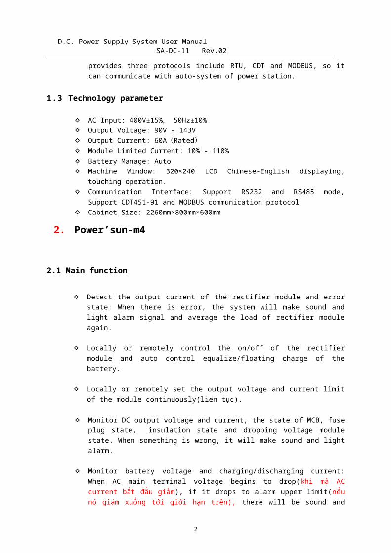
2.2 Monitor System structure
The basic configurations of the monitor system are main monitorunit, AC monitor unit, DC monitor unit, and digital value I/O unit.The optional units are battery detect unit. The above configurationcontains all of the functions of DC system. The theory of system is asfollow:
3
RS485
Main monitor
AC monitor
unit
DC monitor
unit
Digital value
unit
Insulation test
Battery detect
Rectifier module 01
Rectifier module N••••
•• •
Power supply (110VDC)
The theory of system
D.C. Power Supply System User Manual SA-DC-11 Rev.02
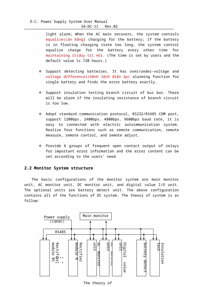
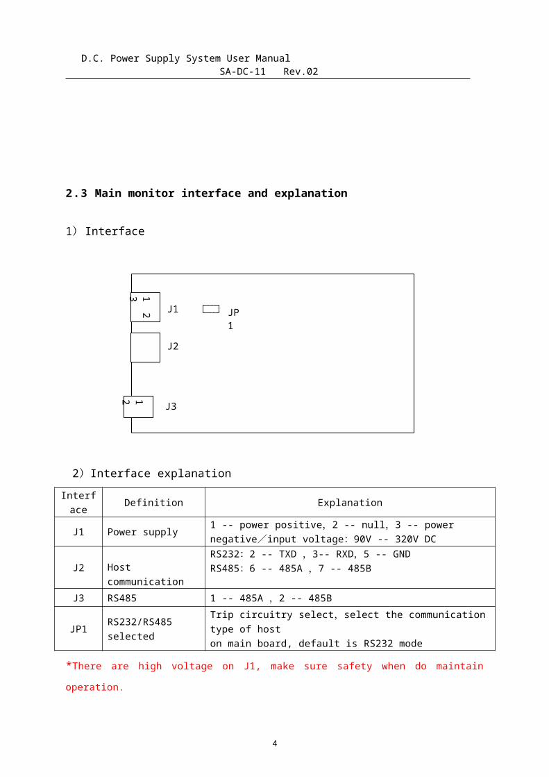
2.3 Main monitor interface and explanation
1)Interface
2)Interface explanationInterface Definition Explanation
J1 Power supply 1 -- power positive,2 -- null,3 -- power negative/input voltage:90V -- 320V DC
J2 Host communication
RS232:2 -- TXD ,3-- RXD,5 -- GNDRS485:6 -- 485A ,7 -- 485B
J3 RS485 1 -- 485A ,2 -- 485B
JP1 RS232/RS485selected
Trip circuitry select,select the communicationtype of hoston main board, default is RS232 mode
*There are high voltage on J1, make sure safety when do maintainoperation.
4
1 2
3
J1
J2
J31 2
JP1
D.C. Power Supply System User Manual SA-DC-11 Rev.02
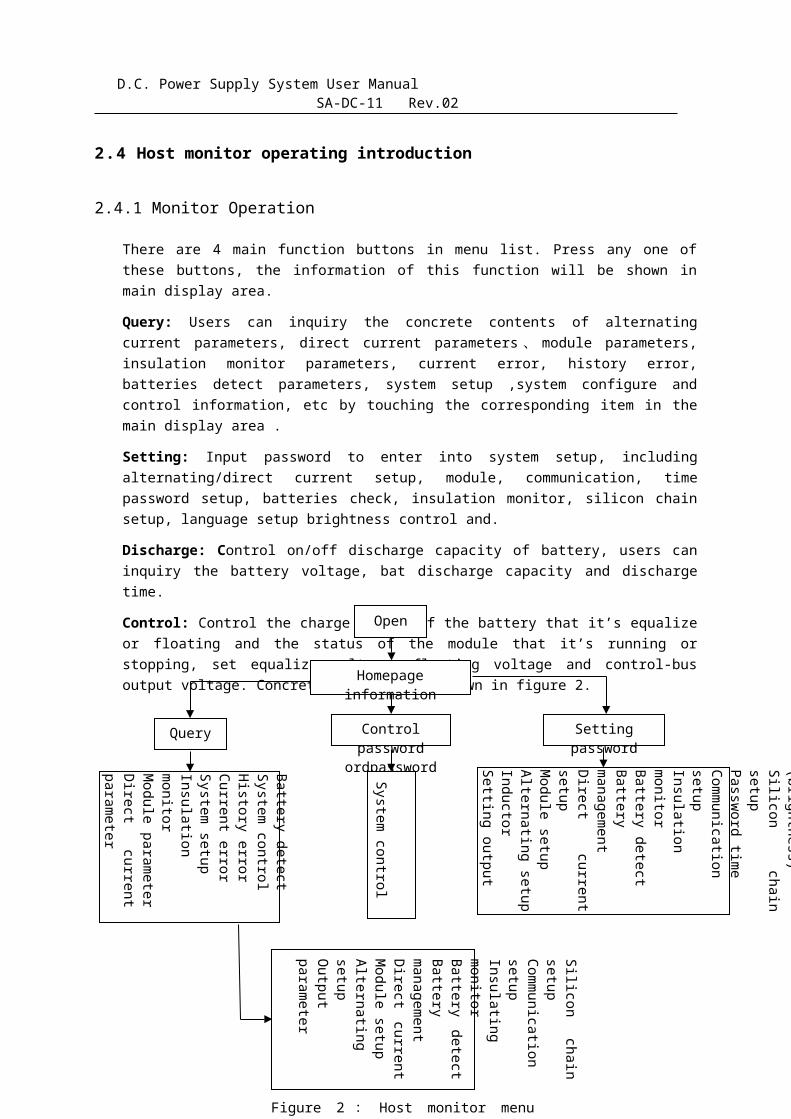
2.4 Host monitor operating introduction
2.4.1 Monitor Operation
There are 4 main function buttons in menu list. Press any one ofthese buttons, the information of this function will be shown inmain display area.
Query: Users can inquiry the concrete contents of alternatingcurrent parameters, direct current parameters 、 module parameters,insulation monitor parameters, current error, history error,batteries detect parameters, system setup ,system configure andcontrol information, etc by touching the corresponding item in themain display area .
Setting: Input password to enter into system setup, includingalternating/direct current setup, module, communication, timepassword setup, batteries check, insulation monitor, silicon chainsetup, language setup brightness control and.
Discharge: Control on/off discharge capacity of battery, users caninquiry the battery voltage, bat discharge capacity and dischargetime.
Control: Control the charge status of the battery that it’s equalizeor floating and the status of the module that it’s running orstopping, set equalize voltage, floating voltage and control-busoutput voltage. Concrete operation is shown in figure 2.
5
Open
Homepage information
Query Setting password
Control password
ordpasswordSystem control
Other (brightness)Silicon
chain setupPassword timeCommunication setupInsulation monitorBattery detectBattery managementDirect
current setup Module setup Alternating setupInductorSetting output
Silicon chain
setupCommunication setupInsulating monitor Battery
detect Battery managementDirect
current Module setupAlternating setupOutput parameter
Battery detect System controlHistory errorCurrent errorSystem setupInsulation monitorModule parameterDirect
current parameter
Figure 2 : Host monitor menu structure
D.C. Power Supply System User Manual SA-DC-11 Rev.02
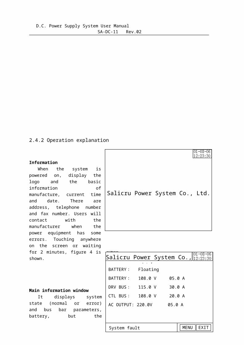
2.4.2 Operation explanation
Information When the system is
powered on, display thelogo and the basicinformation ofmanufacture, current timeand date. There areaddress, telephone numberand fax number. Users willcontact with themanufacturer when thepower equipment has someerrors. Touching anywhereon the screen or waitingfor 2 minutes, figure 4 isshown.
Main information windowIt displays system
state (normal or error)and bus bar parameters,battery, but the
6
Salicru Power System Co., Ltd.
系 系系统Salicru Power System Co.,
Ltd..BATTERY: Floating
BATTERY: 108.0 V 05.0 A
DRV BUS: 115.0 V 30.0 A
CTL BUS: 108.0 V 20.0 A
AC OUTPUT: 220.0V 05.0 A
EXITMENUSystem fault
Salicru Power System Co., Ltd.
System Information ,
please query!
Fault
Models info
History
Battery Set
info
Isolation Ctrl info
EXIT
AC-pars
D.C. Power Supply System User Manual SA-DC-11 Rev.02
displaying contents are according to the system configure. If thesystem is in error, system state displays “Error” and it will soundalarm and flash. Touching “Error” can inquiry current errorinformation. Touching “Menu” can enter into the main menu page.Touching “EXIT” enter into the manufacture information page.
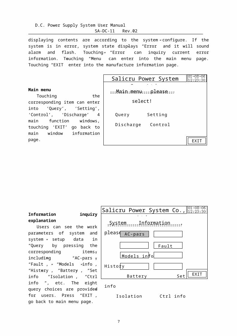
Main menuTouching the
corresponding item can enterinto ‘Query’, ‘Setting’,‘Control’, ‘Discharge’ 4main function windows,touching ‘EXIT’ go back tomain window informationpage.
Information inquiryexplanation
Users can see the workparameters of system andsystem setup data in“Query” by pressing thecorresponding items,including “AC-pars”,“Fault”, “Models info”,“History”, “Battery”, “Setinfo” “Isolation”, “Ctrlinfo “, etc. The eightquery choices are providedfor users. Press “EXIT”,go back to main menu page.
7
Salicru Power System Co., Ltd.
Main menu please
select!
Query Setting
Discharge Control
EXIT
Salicru Power System Co., Ltd.NO.1 AC real-time
parameterFirst AC: workUV: 382.6 VVW: 375.3 VWU: 387.3 V
AC Current: 21 A
EXIT
UpDown
Salicru Power System Co., Ltd.Other measure
parameterTemp: 25.0 0C
EXIT
DownUp
Salicru Power System Co., Ltd.Rectifier work
parameter01: on F.C 108.0V 12.5 A02: on F.C 108.0V 12.5 A03: on DRV
115.0V 15.0 A04: on DRV 115.0V 15.0 A
EXIT
DownUP
D.C. Power Supply System User Manual SA-DC-11 Rev.02
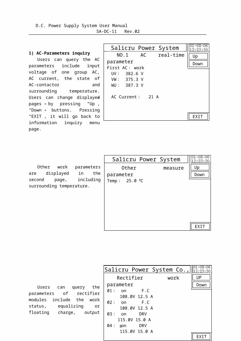
1) AC-Parameters inquiryUsers can query the AC
parameters include inputvoltage of one group AC,AC current, the state ofAC-contactor andsurrounding temperature.Users can change displayedpages by pressing “Up”,“Down” buttons. Pressing“EXIT”, it will go back toinformation inquiry menupage.
Other work parametersare displayed in thesecond page, includingsurrounding temperature.
Users can query theparameters of rectifiermodules include the workstatus, equalizing orfloating charge, output
8
Salicru Power System Co., Ltd.Malfunction now
AC cell 1 halt messageDC cell halt messageRectifier 01 communication faultRectifier 02 communication faultRectifier 03 communication fault
DownUP
EXIT
D.C. Power Supply System User Manual SA-DC-11 Rev.02
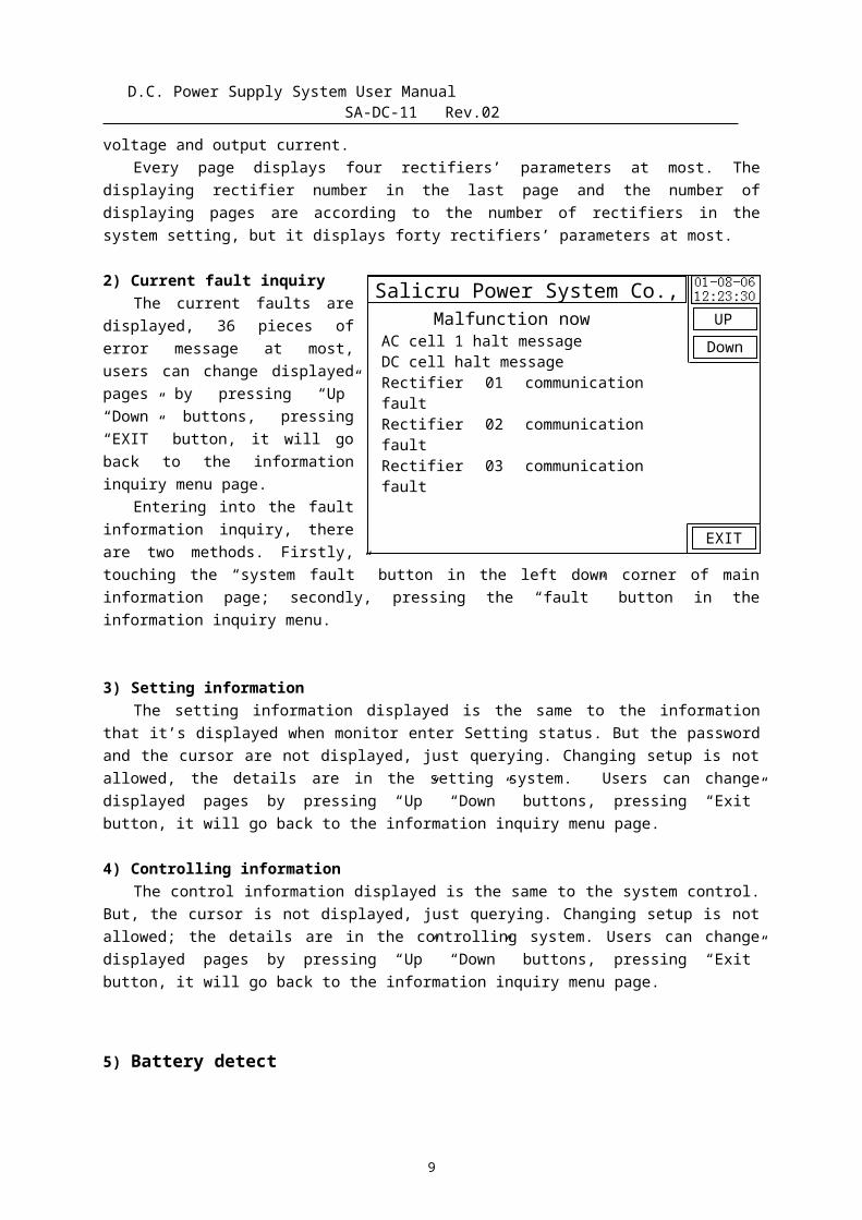
voltage and output current.Every page displays four rectifiers’ parameters at most. The
displaying rectifier number in the last page and the number ofdisplaying pages are according to the number of rectifiers in thesystem setting, but it displays forty rectifiers’ parameters at most.
2) Current fault inquiryThe current faults are
displayed, 36 pieces oferror message at most,users can change displayedpages by pressing “Up”“Down” buttons, pressing“EXIT” button, it will goback to the informationinquiry menu page.
Entering into the faultinformation inquiry, thereare two methods. Firstly,touching the “system fault” button in the left down corner of maininformation page; secondly, pressing the “fault” button in theinformation inquiry menu.
3) Setting informationThe setting information displayed is the same to the information
that it’s displayed when monitor enter Setting status. But the passwordand the cursor are not displayed, just querying. Changing setup is notallowed, the details are in the setting system. Users can changedisplayed pages by pressing “Up” “Down” buttons, pressing “Exit”button, it will go back to the information inquiry menu page.
4) Controlling informationThe control information displayed is the same to the system control.
But, the cursor is not displayed, just querying. Changing setup is notallowed; the details are in the controlling system. Users can changedisplayed pages by pressing “Up” “Down” buttons, pressing “Exit”button, it will go back to the information inquiry menu page.
5) Battery detect
9
Salicru Power System Co., Ltd.
BAT1 lookingMax : 14.25 V 03 nodeMin : 11.57 V 02 nodeBAT check-up is ok
BAT1 temperatureT1: 35.6 ℃ T2: 34.6 ℃
EXIT
DownUp
Salicru Power System Co., Ltd. First Bat Group001: 12:32 V 002: 12:21 V 003: 14:25 V 004: 13:24 V 005: 12:67 V 006: 13:11 V 007: 12:68 V 008: 12:45 V
EXIT
DownUP
Shenzhen Huiyeda Technology Co., Ltd. Isolation measure oneDRV+ VOLT : 058 VCTRL+ VOLT : 051 VBUS- VOLT : 057 V Isolation normal
EXIT
DownUp
D.C. Power Supply System User Manual SA-DC-11 Rev.02
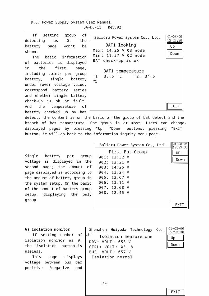
If setting group ofdetecting as 0, thebattery page won’t beshown.
The basic informationof batteries is displayedin the first page,including Joints per groupbattery, single batteryunder /over voltage value,correspond battery seriesand whether single batterycheck-up is ok or fault.And the temperature ofbattery checked up by batdetect, the content is on the basic of the group of bat detect and thebranch of bat temperature. One group is at most. Users can changedisplayed pages by pressing “Up” “Down” buttons, pressing “EXIT”button, it will go back to the information inquiry menu page.
Single battery per groupvoltage is displayed in thesecond page; the amount ofpage displayed is according tothe amount of battery group inthe system setup. On the basicof the amount of battery groupsetup, displaying the onlygroup.
6) Isolation monitorIf setting number of
isolation monitor as 0,the “isolation” button isuseless.
This page displaysvoltage between bus barpositive /negative and
10
Salicru Power System Co., Ltd.
History malfunctionDC cell halt messageSwitch cell 1 halt message Rectifier01 communication fault
Exit
DownUp
Salicru Power System Co., Ltd.
Input setting password:
*****
UpDown
ExitSave
← 。 0
7 8 94 5 61 2 3
Setting
D.C. Power Supply System User Manual SA-DC-11 Rev.02
ground, whether isolation is ok or not; the basic insulationinformation of two buses can be displayed according to monitor the busbar isolation by system. Users can change displayed pages by pressing“Up” “Down” buttons, pressing “EXIT” button, it will go back to theinformation inquiry menu page.
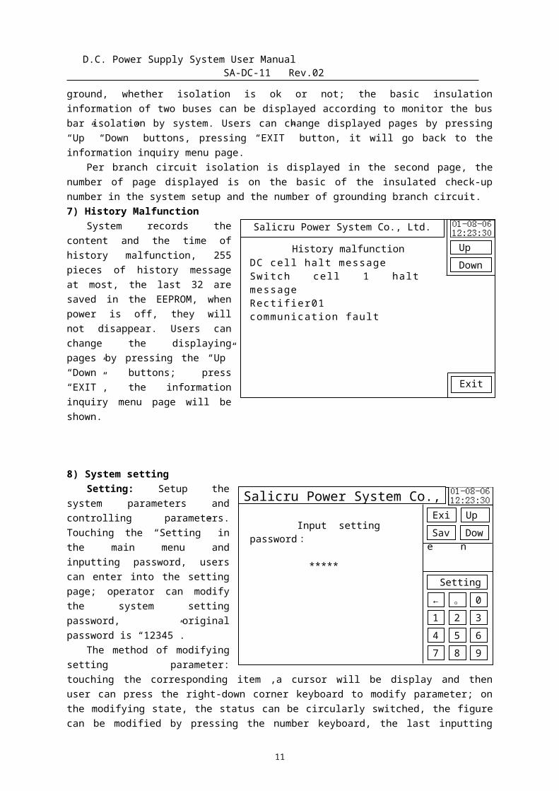
Per branch circuit isolation is displayed in the second page, thenumber of page displayed is on the basic of the insulated check-upnumber in the system setup and the number of grounding branch circuit. 7) History Malfunction
System records thecontent and the time ofhistory malfunction, 255pieces of history messageat most, the last 32 aresaved in the EEPROM, whenpower is off, they willnot disappear. Users canchange the displayingpages by pressing the “Up”“Down” buttons; press“EXIT”, the informationinquiry menu page will beshown.
8) System settingSetting: Setup the
system parameters andcontrolling parameters.Touching the “Setting” inthe main menu andinputting password, userscan enter into the settingpage; operator can modifythe system settingpassword, originalpassword is “12345”.
The method of modifyingsetting parameter:touching the corresponding item ,a cursor will be display and thenuser can press the right-down corner keyboard to modify parameter; onthe modifying state, the status can be circularly switched, the figurecan be modified by pressing the number keyboard, the last inputting
11
Salicru Power System Co., Ltd.
DC parameterDRV high lmt: 122.0 VDRV low lmt: 095.0 VCTRL high lmt: 115.0 VCTRL low lmt: 095.0 VBAT low lmt: 097.0 VKM quot: 100.0 BAT quot: 200.0
UpDownn
ExitSave
← 。 0
7 8 94 5 61 2 3
Setting
Salicru Power System Co., Ltd.
AC parametersupply: bothhigh limit: 437.0 Vlow limit : 342.0 Vinductor: 50
Rectifier parameterNumbers: 4
UpDown
ExitSave
← 。 0
7 8 94 5 61 2 3
Setting
Salicru Power System Co., Ltd.Battery parameter
Mode: autoCapacity: 065 AhLmt curr: 006.5ACvs curr: 1.3 ABC cyc: 90 DLmted BC: 20 HTimed BC: 3 HTem Coe: 0.0 V/0CUnder volt: 195.0V
UpDown
ExitSave
← 。 0
7 8 94 5 61 2 3
Setting
D.C. Power Supply System User Manual SA-DC-11 Rev.02
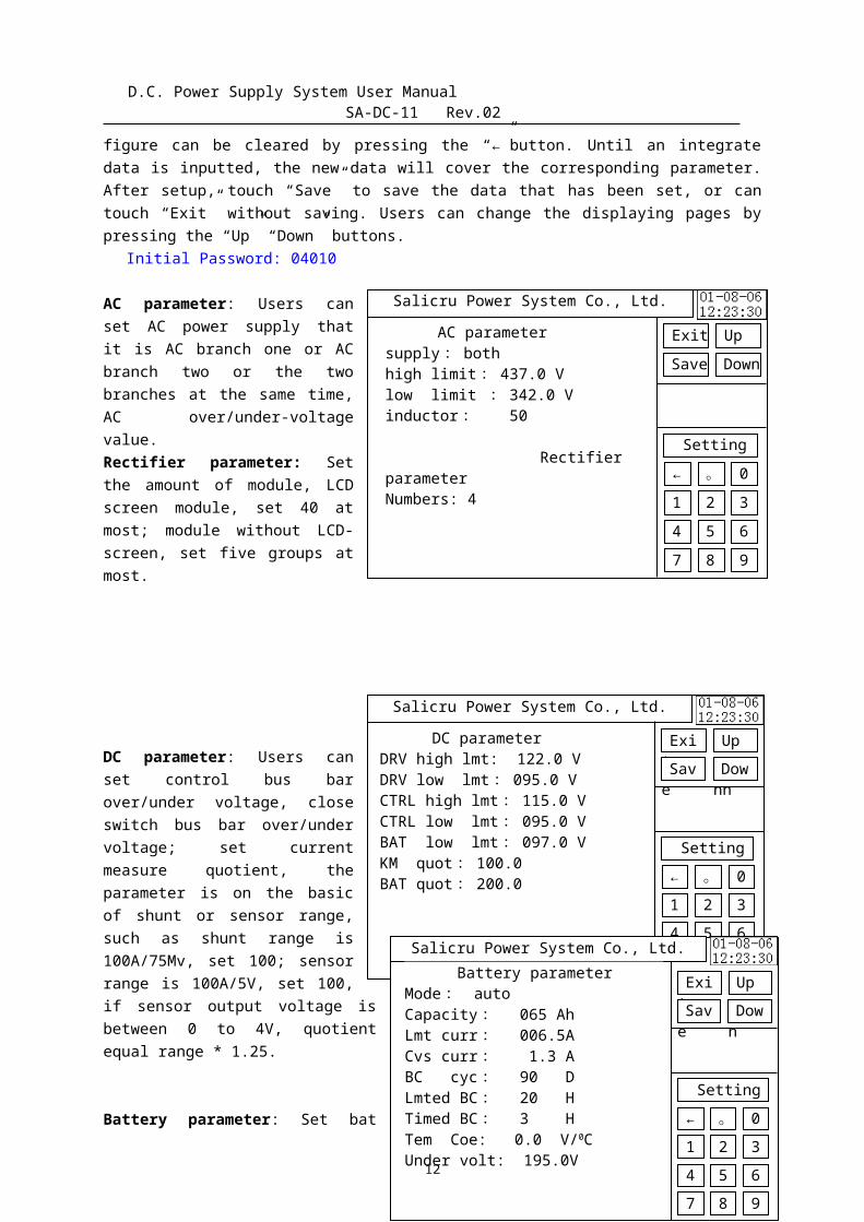
figure can be cleared by pressing the “←”button. Until an integratedata is inputted, the new data will cover the corresponding parameter.After setup, touch “Save” to save the data that has been set, or cantouch “Exit” without saving. Users can change the displaying pages bypressing the “Up” “Down” buttons.
Initial Password: 04010
AC parameter: Users canset AC power supply thatit is AC branch one or ACbranch two or the twobranches at the same time,AC over/under-voltagevalue.Rectifier parameter: Setthe amount of module, LCDscreen module, set 40 atmost; module without LCD-screen, set five groups atmost.
DC parameter: Users canset control bus barover/under voltage, closeswitch bus bar over/undervoltage; set currentmeasure quotient, theparameter is on the basicof shunt or sensor range,such as shunt range is100A/75Mv, set 100; sensorrange is 100A/5V, set 100,if sensor output voltage isbetween 0 to 4V, quotientequal range * 1.25.
Battery parameter: Set bat
12
Salicru Power System Co., Ltd.Insulated check-up
Number: oneResistance: 15.0 KΩImbalance: 25.0 V
UpDown
ExitSave
← 。 0
7 8 94 5 61 2 3
Setting
Salicru Power System Co., Ltd.Battery looking
Groups: oneBat group 1: 08 nodesBat group 2: 18 nodesMonomer high: 15.02 VMonomer low: 11.02 Vdifference: 0.35 Vlast high: 15.02 Vlast low: 0.00 Vtemp number: 2
UpDown
ExitSave
← 。 0
7 8 94 5 61 2 3
Setting
D.C. Power Supply System User Manual SA-DC-11 Rev.02
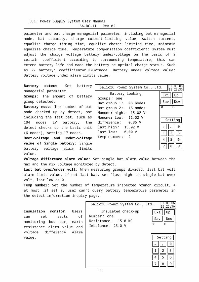
parameter and bat charge managerial parameter, including bat managerialmode, bat capacity, charge current-limiting value, switch current,equalize charge timing time, equalize charge limiting time, maintainequalize charge time. Temperature compensation coefficient: system mustadjust the charge voltage battery under-voltage on the basic of acertain coefficient according to surrounding temperature; this canextend battery life and made the battery be optimal charge status. Suchas 2V battery: coefficient=0.003V*node. Battery under voltage value:Battery voltage under alarm limits value.
Battery detect: Set batterymanagerial parameter.Groups: The amount of batterygroup detected.Battery node: The number of batnode checked up by detect, notincluding the last bat, such as104 nodes 2V battery, thedetect checks up the basic unit(6 nodes), setting 17 nodes.Over-voltage and under-voltagevalue of Single battery: Singlebattery voltage alarm limitsvalue.Voltage difference alarm value: Set single bat alarm value between themax and the mix voltage monitored by detect.Last bat over/under volt: When measuring groups divided, last bat voltalarm limit value, if not last bat, set “last high” as single bat overvolt, last low as 0.Temp number: Set the number of temperature inspected branch circuit, 4at most .if set 0, user can’t query battery temperature parameter inthe detect information inquiry page.
Insulation monitor: Userscan set sects ofmonitoring bus bar, earthresistance alarm value andvoltage difference alarmvalue.
13
Salicru Power System Co., Ltd.Setting output
AC Fault: 0MK Fault: 0MX Fault: 0KZKG Fault: 0HZKG Fault: 0Extra Fault: 0Inside Fault: 0
UpDown
ExitSave
← 。 0
7 8 94 5 61 2 3
Setting
Salicru Power System Co., Ltd.
Com Setting Address: 01Baud Rate: 9600Bit/sProtocol: CDT
Light adjust:
UpDown
ExitSave
← 。 0
7 8 94 5 61 2 3
Setting
D.C. Power Supply System User Manual SA-DC-11 Rev.02
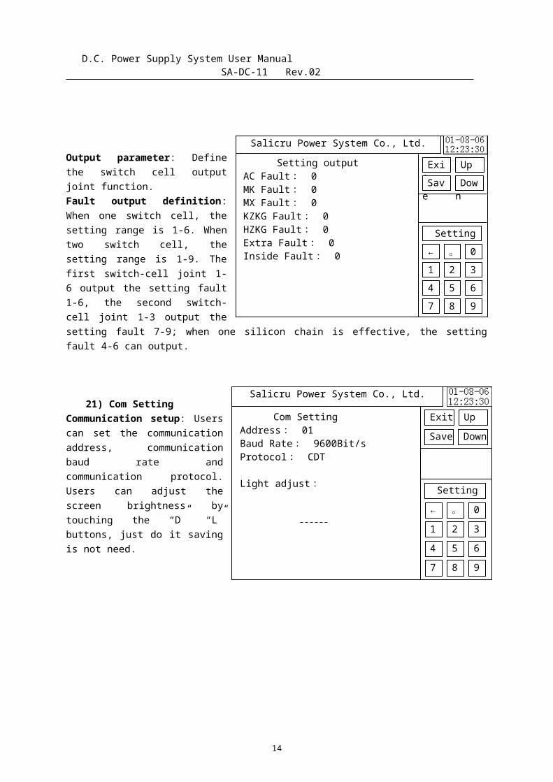
Output parameter: Definethe switch cell outputjoint function.Fault output definition:When one switch cell, thesetting range is 1-6. Whentwo switch cell, thesetting range is 1-9. Thefirst switch-cell joint 1-6 output the setting fault1-6, the second switch-cell joint 1-3 output thesetting fault 7-9; when one silicon chain is effective, the settingfault 4-6 can output.
21) Com SettingCommunication setup: Userscan set the communicationaddress, communicationbaud rate andcommunication protocol.Users can adjust thescreen brightness bytouching the “D” “L”buttons, just do it savingis not need.
14
Salicru Power System Co., Ltd.PSW and Time Setting
Y: 01M: 08D: 06H: 12Min: 23
setting PSW: 12345Control PSW: 12345
UpDown
ExitSave
← 。 0
7 8 94 5 61 2 3
Setting
Salicru Power System Co., Ltd.
Input control password:
* * * * *
Up Down
ExitSave
← 。 0
7 8 94 5 61 2 3
Setting
D.C. Power Supply System User Manual SA-DC-11 Rev.02
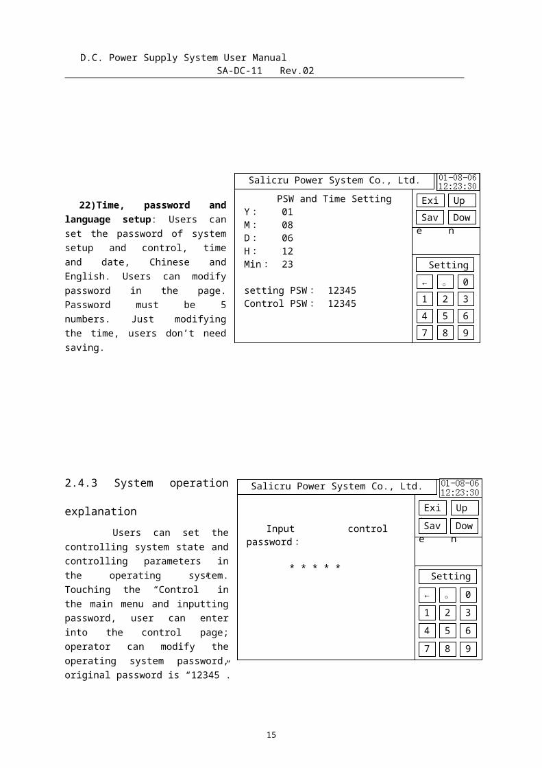
22)Time, password andlanguage setup: Users canset the password of systemsetup and control, timeand date, Chinese andEnglish. Users can modifypassword in the page.Password must be 5numbers. Just modifyingthe time, users don’t needsaving.
2.4.3 System operation
explanation Users can set thecontrolling system state andcontrolling parameters inthe operating system.Touching the “Control” inthe main menu and inputtingpassword, user can enterinto the control page;operator can modify theoperating system password,original password is “12345”.
15
Salicru Power System Co., Ltd.Rectifier operation
01: open02: open03: open
Up Down
Exit Save
← 。 0
7 8 94 5 61 2 3
Setting
Salicru Power System Co., Ltd.
System operation Battery 1: FloatingF.C. volt: 108.0 VB.C. volt: 112.0 VKM output: 115.0 V
Up Down
Exit Save
← 。 0
7 8 94 5 61 2 3
Setting
D.C. Power Supply System User Manual SA-DC-11 Rev.02
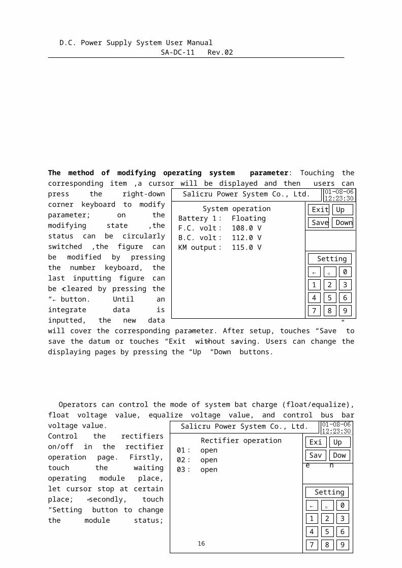
The method of modifying operating system parameter: Touching thecorresponding item ,a cursor will be displayed and then users canpress the right-downcorner keyboard to modifyparameter; on themodifying state ,thestatus can be circularlyswitched ,the figure canbe modified by pressingthe number keyboard, thelast inputting figure canbe cleared by pressing the“←”button. Until anintegrate data isinputted, the new datawill cover the corresponding parameter. After setup, touches “Save” tosave the datum or touches “Exit” without saving. Users can change thedisplaying pages by pressing the “Up” “Down” buttons.
Operators can control the mode of system bat charge (float/equalize),float voltage value, equalize voltage value, and control bus barvoltage value.Control the rectifierson/off in the rectifieroperation page. Firstly,touch the waitingoperating module place,let cursor stop at certainplace; secondly, touch“Setting” button to changethe module status;
16
Salicru Power System Co., Ltd.
Measure BAT1 cap: Stop
BAT1 volt: 102.0 V
Capacity : 028.0 Ah
Time(h/m/s) : 03 : 57 :
33
Up Down
Clean Exit
Salicru Power System Co., Ltd.
Isolation resistance
one
No grounding
Exit
Down
D.C. Power Supply System User Manual SA-DC-11 Rev.02
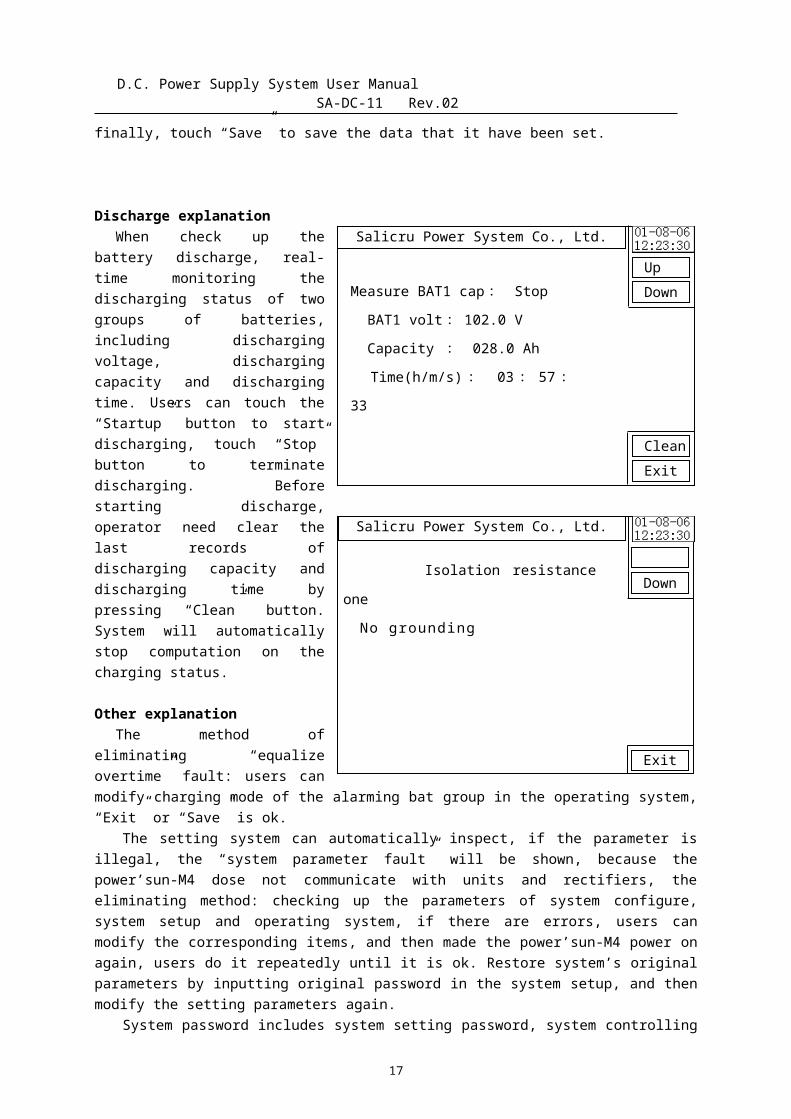
finally, touch “Save” to save the data that it have been set.
Discharge explanationWhen check up the
battery discharge, real-time monitoring thedischarging status of twogroups of batteries,including dischargingvoltage, dischargingcapacity and dischargingtime. Users can touch the“Startup” button to startdischarging, touch “Stop”button to terminatedischarging. Beforestarting discharge,operator need clear thelast records ofdischarging capacity anddischarging time bypressing “Clean” button.System will automaticallystop computation on thecharging status.
Other explanationThe method of
eliminating “equalizeovertime” fault: users canmodify charging mode of the alarming bat group in the operating system,“Exit” or “Save” is ok.
The setting system can automatically inspect, if the parameter isillegal, the “system parameter fault” will be shown, because thepower’sun-M4 dose not communicate with units and rectifiers, theeliminating method: checking up the parameters of system configure,system setup and operating system, if there are errors, users canmodify the corresponding items, and then made the power’sun-M4 power onagain, users do it repeatedly until it is ok. Restore system’s originalparameters by inputting original password in the system setup, and thenmodify the setting parameters again.
System password includes system setting password, system controlling
17
D.C. Power Supply System User Manual SA-DC-11 Rev.02
password (be freely modified), system configure password (manager usesit, can’t modify it, it is the super password of the setting system andthe operating system), original password (manager uses it, can’t modifyit. when use it, restore the system’s original parameters)
Make sure system configure right, enter into the systemsetup.
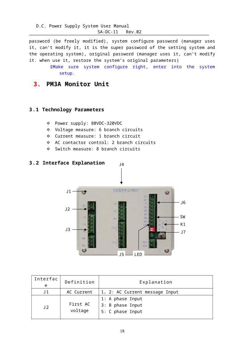
3. PM3A Monitor Unit
3.1 Technology Parameters
Power supply: 80VDC-320VDC Voltage measure: 6 branch circuits Current measure: 1 branch circuit AC contactor control: 2 branch circuits Switch measure: 8 branch circuits
3.2 Interface Explanation
Interface Definition Explanation
J1 AC Current 1、2:AC Current message Input
J2 First ACvoltage
1:A phase Input3:B phase Input5:C phase Input
18
J2
J3
J5
J7
J6
LED
SWK1
J1
J4
D.C. Power Supply System User Manual SA-DC-11 Rev.02
2、4:NC
J3 Power Supply
1:Power positive3:Power negative2:NCInput voltage:80VDC ~ 320VDC
J4 Second ACvoltage
1:AA phase Input 3:B phase Input5:C phase Input2、4:NC
J5 Contactorcontrol
1、3:First AC control5、7:Second AC control2、4、6:NC
J6 Statusmeasure
1:first Contactor state2:second Contactor state3、Message of avoiding thunder4-8:AC Switch state9、Com
LED Work LED The LED is twinkling when AC unitwork normally
J7 RS485 1:RS485A2:RS485B
SW Unitsetting
Setting address of the unit
K1 Work modeLeft:Switch on second inputting ACMiddle:AutoRihgt:Switch on first inputting AC
There is AC voltage on J2, J4, J5, so it’s necessary to make
sure safety that operators cut off the two inputting AC powers
before starting to maintain.
There are high voltage on J3, make sure safety at the same time
maintain.
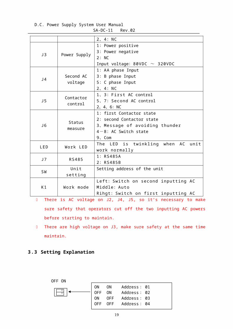
3.3 Setting Explanation
19
ON ON Address: 01OFF ON Address: 02ON OFF Address: 03OFF OFF Address: 04
OFF ON
J1
J3
J5
J6
J7
LED
J2
J4 SW
D.C. Power Supply System User Manual SA-DC-11 Rev.02
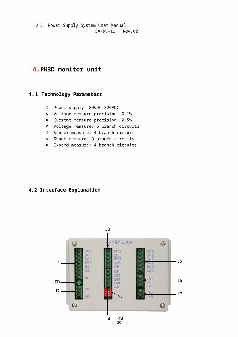
4.PM3D monitor unit
4.1 Technology Parameters
Power supply: 80VDC-320VDC Voltage measure precision: 0.1% Current measure precision: 0.5% Voltage measure: 6 branch circuits Sensor measure: 4 branch circuits Shunt measure: 3 branch circuits Expand measure: 4 branch circuits
4.2 Interface Explanation
20
D.C. Power Supply System User Manual SA-DC-11 Rev.02
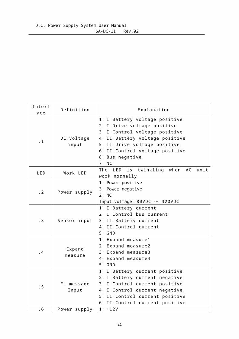
Interface Definition Explanation
J1 DC Voltageinput
1:I Battery voltage positive2:I Drive voltage positive3:I Control voltage positive4:II Battery voltage positive5:II Drive voltage positive6:II Control voltage positive8:Bus negative7:NC
LED Work LED The LED is twinkling when AC unitwork normally
J2 Power supply
1:Power positive3:Power negative2:NCInput voltage:80VDC ~ 320VDC
J3 Sensor input
1:I Battery current2:I Control bus current3:II Battery current4:II Control current5:GND
J4 Expandmeasure
1:Expand measure12:Expand measure23:Expand measure34:Expand measure45:GND
J5 FL messageInput
1:I Battery current positive2:I Battery current negative3:I Control current positive4:I Control current negative5:II Control current positive6:II Control current positive
J6 Power supply 1:+12V
21

D.C. Power Supply System User Manual SA-DC-11 Rev.02
for sensor 2:GND3:-12V
J7 RS485 1:RS485A2:RS485B
SW Unit setting Concrete explanation is shown in“setting”
4.3 Setting Explanation
5. PM3K Switch Monitor Unit
5.1 Technology Parameters
Power voltage: 80VDC-320VDC Feed switch inspect: 32 branch circuits Other state inspect: 8 branch circuits Replay output: 7 branch circuits
5.2 Interface Explanation
22
J1
J2
J3
J4
J5
J6
J7
J8
J9
J10
J11
J12
LEDSW1
1 : on Battery1 FL measure off Battery1 Sensor measure2 : on Control Bus1 FL measure off Control Bus1 Sensor measure3 : on Control Bus2 FL measure off Control Bus2 Sensor measure4: on PM1 and PM2 off PM3 and PM4
1 2
3 4
OFF ON

D.C. Power Supply System User Manual SA-DC-11 Rev.02
Interface Definition Explanation
JP1 choice System fault output interface J1NO/NC choice
J1 System faultoutput System fault output
J2 Fault classifyoutput
Fault classify output 1-3 branchcircuit
J3 Fault classifyoutput
Fault classify output 4-6 branchcircuit
J4 Switch input 1-6:Switch 01-06 input(NO)
J5 Switch input 1-6:Switch 07-12 input(NO)7:Switch input com
J6 Switch input 1-6:Switch 13-18 input(NO)
J7 Switch input 1-6:Switch 01-06 input(NO)7:Switch input com
J8 Switch input 1-6:Switch 01-06 input(NO)
J9 Switch input
1-2:Switch 31-32 input(NO)3-4:Battery Switch 1-2 input(NO)5-6 : Exterior equipment 1-2input(NO)7:Switch input com
J10 Switch input
1-2:Fusion 1-2 input(NO)3-4 : Insulation monitor 1-2input(NO)5:Switch input com
LED Work LED The LED is twinkling when AC unitwork normally
23
D.C. Power Supply System User Manual SA-DC-11 Rev.02
J11 RS485 1: 485A, 2: 485B
J12 Power supply
1:Power positive3:Power negative2:NCInput voltage:90VDC ~ 320VDC
SW Unit setting Concrete explanation is shown in“setting”
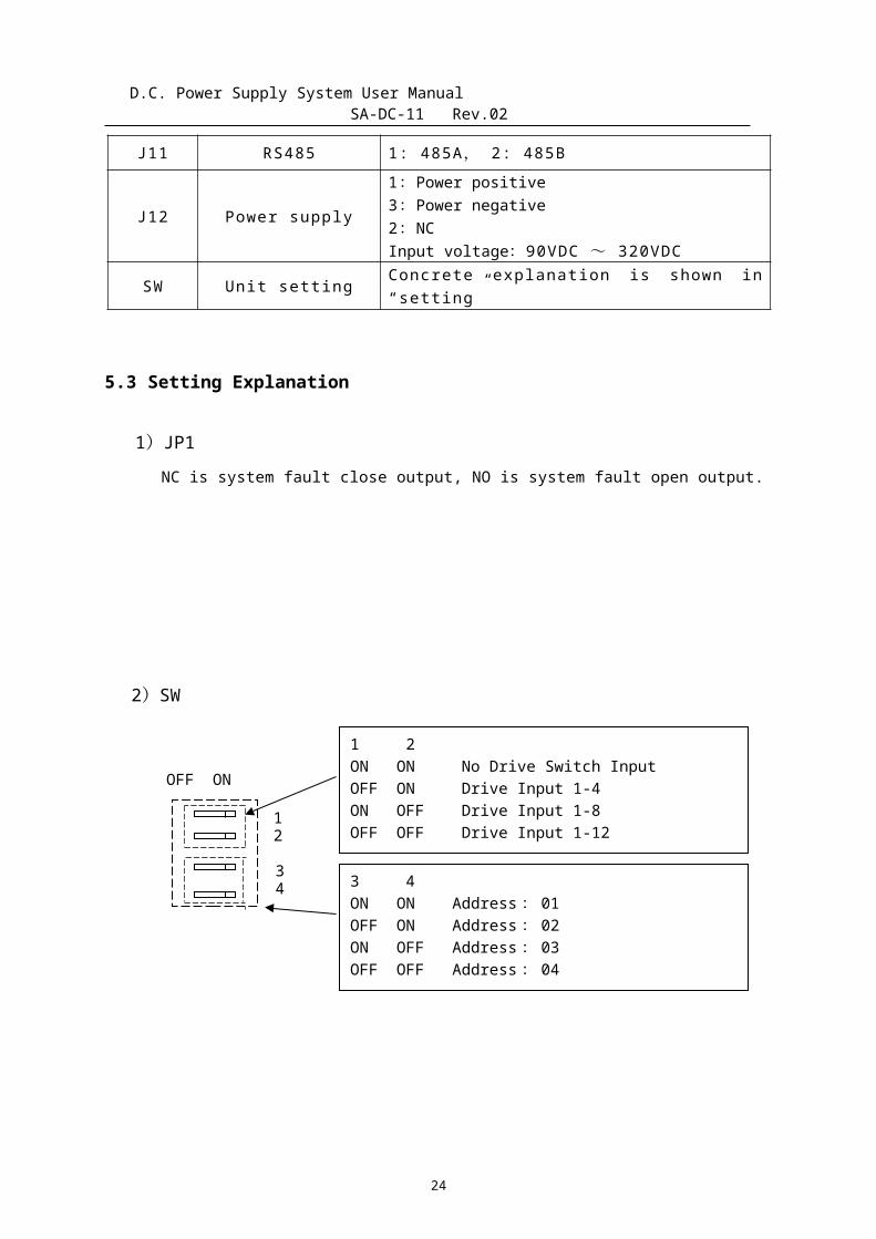
5.3 Setting Explanation
1)JP1 NC is system fault close output, NO is system fault open output.
2)SW
24
1 2ON ON No Drive Switch InputOFF ON Drive Input 1-4ON OFF Drive Input 1-8OFF OFF Drive Input 1-12
3 4ON ON Address: 01OFF ON Address: 02ON OFF Address: 03OFF OFF Address: 04
OFF ON
12
34
D.C. Power Supply System User Manual SA-DC-11 Rev.02
6. K2A20L RECTIFIER
6.1 Error Alarm
If module has a failure occurs, the buzzer will sound, the state-LED
will flicker and the LCD screen will display the error messages
defined in the following table.
Message Displayed Explanation
O.T PRO Over Temperature Protection
O.V PRO Over Voltage Protection
O.C PRO Over Current Protection
O.V ALAM Over Voltage Alarm
L.V ALAM Low Voltage Alarm
AC PRO AC Protection
SOFT PRO Software Protection
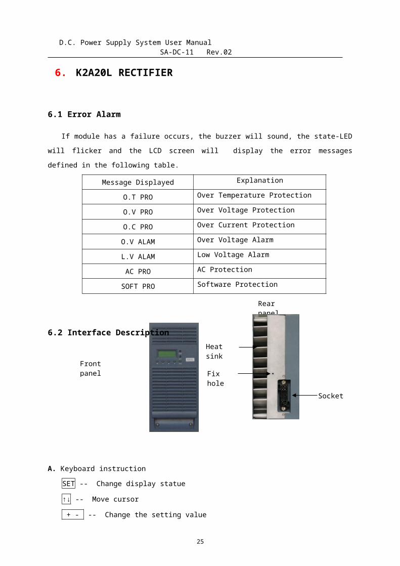
6.2 Interface Description
A. Keyboard instruction
SET -- Change display statue
↑↓ -- Move cursor
+ - -- Change the setting value
25
Frontpanel
Socket
Heat sink
Fix hole
Rear panel
SETUP ◆ RUN
ADJUST EQUALIZE
D.C. Power Supply System User Manual SA-DC-11 Rev.02
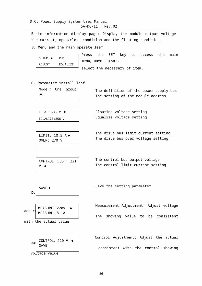
Basic information display page: Display the module output voltage,the current, open/close condition and the floating condition.
B. Menu and the main operate leaf
Press the SET key to access the mainmenu,move cursor,
select the necessary of item.
C. Parameter install leaf
The definition of the power supply busThe setting of the module address
Floating voltage settingEqualize voltage setting
The drive bus limit current settingThe drive bus over voltage setting
The control bus output voltageThe control limit current setting
Save the setting parameter D. 测测测测测
Measurement Adjustment: Adjust voltageand current
The showing value to be consistentwith the actual value
Control Adjustment: Adjust the actualoutput value to be
consistent with the control showingvoltage value
26
Mode : One Group◆ADD:12
FLOAT: 245 V ◆EQUALIZE:256 V
LIMIT: 10.5 A◆ OVER: 270 V
CONTROL BUS : 221V ◆ LIMIT: 10.5 A
SAVE◆
MEASURE:220V ◆ MEASURE:8.1A
CONTROL:220 V ◆SAVE
D.C. Power Supply System User Manual SA-DC-11 Rev.02
E. The leaf of failure information
Fault showing message: Overtemperature protection,
Over voltage protection, ACprotection, Over current
protection, Over voltage alarm, Lowvoltage alarm
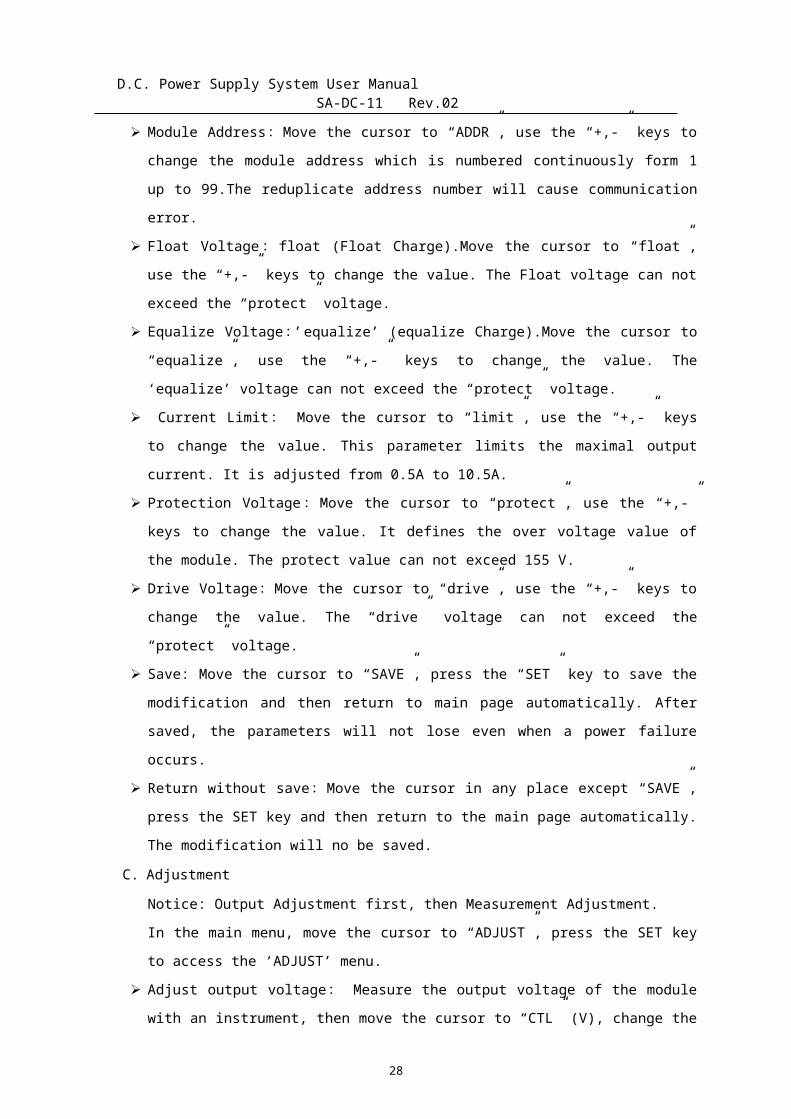
6.3 Operation Flow-Chart
6.4 Operation Manual
A. Switch the running mode/Charging mode
Accessing the main menu, use the cursor keys to select a target,
then press the SET key and press it again for confirming.
B. Set the Parameters
In the main menu, move the cursor to “SETUP”, press the SET key
to access the SETUP menu.
Output mode : Move the cursor to “BUS”, use the “+,-” key to
change the output mode. DRIVE/GRP ONE/GPR TWO – Different BUSES.
27
Over temperature protection
D.C. Power Supply System User Manual SA-DC-11 Rev.02
Module Address:Move the cursor to “ADDR”, use the “+,-” keys to
change the module address which is numbered continuously form 1
up to 99.The reduplicate address number will cause communication
error.
Float Voltage: float (Float Charge).Move the cursor to “float”,
use the “+,-” keys to change the value. The Float voltage can not
exceed the “protect” voltage.
Equalize Voltage ’: equalize’ (equalize Charge).Move the cursor to
“equalize”, use the “+,-” keys to change the value. The
‘equalize’ voltage can not exceed the “protect” voltage.
Current Limit : Move the cursor to “limit”, use the “+,-” keys
to change the value. This parameter limits the maximal output
current. It is adjusted from 0.5A to 10.5A.
Protection Voltage:Move the cursor to “protect”, use the “+,-”
keys to change the value. It defines the over voltage value of
the module. The protect value can not exceed 155 V.
Drive Voltage:Move the cursor to “drive”, use the “+,-” keys to
change the value. The “drive” voltage can not exceed the
“protect” voltage.
Save: Move the cursor to “SAVE”, press the “SET” key to save the
modification and then return to main page automatically. After
saved, the parameters will not lose even when a power failure
occurs.
Return without save:Move the cursor in any place except “SAVE”,
press the SET key and then return to the main page automatically.
The modification will no be saved.
C. Adjustment
Notice: Output Adjustment first, then Measurement Adjustment.
In the main menu, move the cursor to “ADJUST”, press the SET key
to access the ‘ADJUST’ menu.
Adjust output voltage : Measure the output voltage of the module
with an instrument, then move the cursor to “CTL” (V), change the
28
D.C. Power Supply System User Manual SA-DC-11 Rev.02
measured output voltage by press the “+,-” keys. Adjust the
output voltage to be equal to the show voltage. Then move the
cursor to “SAVE”, press SET key to save the modification.
Adjust measured voltage: Move the cursor to “measure” (V),
measure the actual voltage, press the “+,-” keys to adjust the
show voltage to be equal to the actual voltage. Then move the
cursor to ‘SAVE’, press SET key to save the modification.
Adjust measured current: Move the cursor to “measure” (A),
measure the actual current, press the “+,-” keys to adjust the
show voltage to be equal to the actual current., then move the
cursor to “SAVE”, press SET key to save the modification.
Return without save : Settle the cursor in any place except
“SAVE”, press the SET key and then return to the main page
automatically. The modification will no be saved.
A. module adjustment
*Prompt specially: When make the module adjustment it must to bethe principle that firstly adjust control then adjust measure
Voltage control adjustment: The cursor moves to “Voltage controladjustment”, at this time the displaying voltage is the settingworking voltage of the current module. Measure the module outputvoltage, by pressing “+、 -”key , the module output voltage canrise or fall correspondingly, display invariably, the adjustmentrequest output voltage is the display voltage, after adjustmentmove the cursor to “Save”, press the “Setting” key to save.
Measure voltage adjustment: The cursor moves to “Measure voltageadjustment”, measure the actual output voltage, by pressing“+、-”key adjust the display value to the actual observed value ,move the cursor to “Save”, press “Setting” to save.
Measure current adjustment: The cursor moves to “Measure currentadjustment”, measure the actual output voltage(Request thecurrent is more than the module rated current 50%), by pressing
29
D.C. Power Supply System User Manual SA-DC-11 Rev.02
“+、-”key adjust the display value to the actual observed value ,move the cursor to “Save”, press “Setting” to save.
No saving return: The cursor is in any position except “Save”,press “Setting” to return to the basic message display page, theparameter revision is invalid at this time, module according tooriginal parameter runs.
7. Common fault processing
7.1 PM4 common fault processing
Fault name: Monitor blue screenFault phenomenon: The monitor does not have any display, does not stop
the twinkle
Reason analysis: The monitor has not inspect the data
Processing method: Disassemble the host monitor, insert the data bus
again. If supply power the display is
still exceptional, had to relate with the company to
replace this host monitor
Fault name: The monitor is fuzzy
Fault phenomenon: The monitor has the display, but displays gloomily,
not easy to distinguish
Reason analysis: The brightness adjustment of the monitor is
unreasonable
Processing method: The different model monitor adjustment display
brightness method is as follows
PM3, PM3BJ liquid crystal box monitor: In main page, press
key to increase the monitor brightness, press key to
reduce the monitor brightness, when adjust brightness need
press key which does not stop until the brightness is
appropriate;
30
D.C. Power Supply System User Manual SA-DC-11 Rev.02
PM4 touching screen monitor: Adjust the brightness must to
be on “The system setting/the brightness adjustment”
Fault name: Monitor black screen
Fault phenomenon: Monitor black screen, when pressed key the buzzer is
not loud
Reason analysis: The liquid-crystal display has not worked
Processing method: Inspect whether there is 90--320V voltage on the
power terminal of the host monitor, if
there is no voltage inspect whether the power bus
becomes less crowded, if normal
must relate with our company to replace this host
monitor
Fault name: The touching screen response is not keen
Fault phenomenon: The touching screen display is normal, but when
touches the display monitor, pressed
key function shifts or does not have the response
Reason analysis: The touching scope must be redefined
Processing method: Adjust the touching screen, the concrete step is as
follows
1. Separate the host monitor power, press the display monitor to
obtain the electricity, the monitor enters the updating
procedure again;
2. According to the monitor prompt “Please click on the left-
top corner luminescent spot”, clicks on the top left-hand
corner luminescent spot gently with tiny hard;
3. According to the monitor prompt “Please click on the right-
under corner luminescent spot, clicks on the right-under
corner luminescent spot gently with tiny hard;
31
D.C. Power Supply System User Manual SA-DC-11 Rev.02
4. The monitor enters the host contact surface, the adjustment
completes;
5. If the pressed key is not exact, may repeat the above
operation.
Fault name: Communication fault
Fault phenomenon: The host monitor sends out all or the part monitor
unit, the module communication
Fault.
Reason analysis: The host monitor communication fault, disposes are not
correct or the transmission line
wiring is not correct,
Processing method:
1. Inspect whether the host monitor disposition is consistent
with the actual disposition;
2. Inspect whether all 485 connections are correct, namely the
485A join the 485A, the 485B join the 485B, examined whether
485 signal line contacts are good, whether there is the
loosening phenomenon;
3. Separate all 485, inspect whether the 485A or 485B of each
unit has about 3V voltage, whether the corresponding monitor
unit work indicating lamp does glitter, if not normal must
relate with our company to replace the corresponding monitor
unit;
4. The host monitor carries on the communication solely with
each monitor unit, if it cannot communicate with some monitor
unit have to inspect whether the code switch position of this
unit is correct, if correct must relate with our company to
replace this monitor unit; If it cannot communicate with
every unit have to relate with our company to replace this
32
D.C. Power Supply System User Manual SA-DC-11 Rev.02
host monitor.
Fault name: Discontinuously sent out the communication faultFault phenomenon: Sometimes the host monitor sent out the monitor unitor the module communication fault, sometimes normalReason analysis: The monitor unit or the module has the disturbance
Processing method:
1. Draw out each monitor unit or the module one by one, examine
whether the host monitor sends out other monitor unit or the
module communication fault besides does send out the
corresponding monitoring unit or the module communication
fault; If after draws out the sole monitor unit or the
module, other communication fault has not eliminated, then
this monitor is normal;
2. If draws out the sole monitor or the module besides sends out
this monitor unit or the module communication fault, other
communication fault vanishes, then this monitor unit or the
module disturb other monitor or the module communication
fault, must relate with our company to replace this module or
the monitor unit.
Fault name: It is unable to inquire the battery or the insulationinspection informationFault phenomenon: Click on the battery inspection or the insulationmenu does not have the responseReason analysis: The host monitor has not disposedProcessing method: Inspect whether the “System disposition” menu of the
host monitor is consistent with the actual disposition, namely
the actual disposition has a battery inspection, in the system
disposition sets 1, has two insulation inspection to dispose 2,
in the system disposition has disposed any monitor unit, in the
33
D.C. Power Supply System User Manual SA-DC-11 Rev.02
menu also had to set the corresponding monitor unit and the
number in “System setting”;; the system disposition password
“98315”, also was the super password of the system setting and
the system operation (Uses it when user forgets password).
Fault name: Background communication faultFault phenomenon: The host monitor and the background cannotcommunicateReason analysis: The data transfer exceptionally or the wiring is notcorrectProcessing method:
1. Processing method: Inspect whether the host monitor
communication protocol, the address and the baud-rate are
consistent with the background choice, if not same must
change the same;
2. Inspect whether the RS485/RS232 mode choice is consistent
with the background, our company is generally the RS232 mode,
if uses 485 mode have to change the 232 jump-line to the 485
jump-line of the monitor internal JP1;
3. Inspect whether the communication connection wiring is
correct, when RS232 wiring, connect a terminal RX(TX) pin
with another terminal TX(RX) pin, all GND pins are joined;
When RS485 wiring, connect a terminal 485A(485B) pin with
another terminal 485A(485B) pin;
4. When it communicates with the background the individual data
is not correct, please relate with our company;
5. If according to the above step inspection still could not the
communication, have to relate with our company replaces this
host monitoring.
Fault name: The equalize/floating transformation is unusual
34

D.C. Power Supply System User Manual SA-DC-11 Rev.02
Fault phenomenon: The monitor cannot transfer from the floating to theequalize automaticallyReason analysis: The host monitor fault, setting is not correct or thewiring is not correctProcessing method:
1. Inspect whether the host monitor “System setting/management
mode” sets automatic, if it is manual need to change into
automatic;
2. Inspect whether the battery current is consistent with the
actual current, if it is inconsistent and is multiple
difference need to examine whether “the battery current
divider” in the host monitor “System setting” is consistent
with the actual disposition. When it is not identically but
difference is not much may (have the F symbol) adjust the
gain potentiometer of the current sensor;
3. If the battery circuit is consistent with the actual current
need to examine whether “the transformation current” in the
host monitor “System setting” sets according to the actual
battery capacity 1%-2%.
Fault name: Equalize is overtimeFault phenomenon: The monitor sends out the equalize overtime faultReason analysis: The system setting is not correctProcessing method:
1. Inspect whether the host monitor “System setting/battery
parameter setting/management mode sets automatic, if it is
manual need to change into automatic;
2. When the system disposes PM3A and also only one group AC
inputs, inspect whether the AC monitor unit J6 AST and COM
port connect with the AC contactor NO, if the system has not
disposed the AC contactor need to connect AST with the COM
port;
3. Inspect whether the battery management parameter in the
35

D.C. Power Supply System User Manual SA-DC-11 Rev.02
system setting does conform to the requirement
Equalize separation:90days
Equalize limite:20hours
Fixed-time equalize:3hours
4. Enter the system operation, change the group charging way
from “Equalize” to “Floating”
Fault name: Battery capacity deviationFault phenomenon: The battery capacity percent is inconsistent with themonitor displaying capacity percentReason analysis: The system setting is not correctProcessing method:
Enter the host monitor “System setting/DC parameter setting/control bus current divider/ the coefficient of the batterycurrent divider setting”, inspect whether is consistent withthe actual current divider coefficient. If consistent need toseparate the system battery switch, in the non-charging currentsituation examined whether the battery current is zero,simultaneously the host monitor displayed the floating, if thehost monitor displayed discharge need to adjust the zeropotentiometer of the sensor (have “O” symbol).
7.2 K2A20 Lmodule common fault processing
Fault name: Module displaying screen fault.Fault phenomenon: The module does not display or the black screen.Reason analysis: The monitor has not inspected the data or has notworked.Processing method: Inspect whether the module contact with the bracketwell, the module interior all interfaces whether is reliable, if becomeless crowded must insert again, if contact well must relate with thefactory..
Fault name: Module protection fault.Fault phenomenon: The monitor sends out the over-warm protection, theover-voltage protection.Reason analysis: The module monitor has not inspected the data.
36
D.C. Power Supply System User Manual SA-DC-11 Rev.02
Processing method: Inspect the module interior interface what connectto the displaying panel whether become less crowded. If become less crowded must
insert again, the module works
normally; if after insert, still could not eliminate
the protection fault must relate with
the factory .
Fault name: Module current deviationFault phenomenon: There is the module current displaying, but is biggerthan the actual outputReason analysis: The current collection is unusualProcessing method: Calibrate current on the module monitor, inspect the
module interior all interfaces
whether become less crowded, if become less crowded
must insert again, if contact
well must relate with the factory.
Fault name: The module under-voltageFault phenomenon: The module sends out the under-voltage alarm, theoutput voltage is lower than 180V (the 220V system) or 90V (the 110Vsystem)Reason analysis: The module output insurance has been damaged or themodule is at the limited current conditionProcessing method:
1. Inspect the system whether is at the limited current equalize
condition, if is, then is normally;
2. Inspect the module output insurance whether has been damaged,
if insurance normal, then must relate with the factory.
Fault name: Module communication faultFault phenomenon: The host monitor sends out the module communicationfault discontinuously and circularlyReason analysis: A module disturbs other module communication fault
37
D.C. Power Supply System User Manual SA-DC-11 Rev.02
Processing method: The single module communicates with the hostmonitor, find out the concrete fault module to relate with the factory.
7.3 AC monitor unit common fault processing
Fault name: The contactor does not attract gatherFault phenomenon: The AC first group does not attract gatherReason analysis: The AC first group contactor does not workProcessing method:
1. Inspect whether the AC monitor switch is keeping on the
automatic position or on forced A group;
2. Inspect whether the wiring is correct, reliable;
3. Connect the first group control terminal of the monitor unit,
measure the coil of the first group AC contactor;
If the coil voltage is normal the contactor still could
not work, need to replace the AC contactor;
If the coil does not have the voltage or abnormity,
must inspect the circuit;
If the contactor can attract gather after supplied
power, need to inspect whether the AC monitor internal
fuse is cut off. If cut off need to replace, if normal
must relate with our company to replace this monitor
unit.
Fault name: The AC cannot switch automatically Fault phenomenon: The AC first group cannot supply power, the second group cannot attract gatherReason analysis: The AC second group contactor does not workProcessing method:
1. Inspect the switch whether is keeping on the automatic
position;
2. Inspect when the AC first group cannot supply power, the AC
monitor whether has the work power;
38
D.C. Power Supply System User Manual SA-DC-11 Rev.02
3. Inspect whether the wiring is correct, reliable;
4. Connect the second group control terminal, measure the coil
of the second group AC contactor:
If the coil voltage is normal, the contactor still
could not work, need to replace the AC contactor;
If the coil does not have the voltage or abnormity,
must inspect the circuit;
If the contactor can attract gather after supplied
power, need to inspect whether the AC monitor internal
fuse is cut off. If cut off need to replace, if normal
must relate with our company to replace this monitor
unit.
Fault name: The AC is over-voltage or under-voltage Fault phenomenon: The host monitor sends out the AC voltage is over or under Reason analysis: The AC voltage of the monitor inspected is out of the enactment scopeProcessing method:
1. Inspect the AC over/under voltage value in the host monitor
menu “System setting” whether is correct (the AC over-voltage
value is 437V, under-voltage value is 323V);
2. Measure the actual AC voltage whether is consistent with the
host monitor displaying value. If the actual voltage is out
of the enactment scope, need to adjust the AC voltage to
lower, avoid the accident expanding; If the actual value is
more different from the displaying value, must relate with
our company to replace this unit.
Fault name: Communication faultFault phenomenon: The host monitor sends out the AC monitor communication fault
39
D.C. Power Supply System User Manual SA-DC-11 Rev.02
Reason analysis: The host monitor has not inspected the AC voltage and the currentProcessing method:
1. Inspect this unit work voltage J2 (namely the PWR+ port)
whether is normal (90-320V).If there is no work voltage, must
inspect the wiring whether is correct, reliable;
2. The work lamp glitters whether normal (normal is glistens
discontinuously).If works unusually, must insert its work
power again;
3. Inspect the unit code switch whether sets correctly;
4. Inspect the switch quantity monitor unit connected with the
host monitor 485 wiring whether is correct, reliable;
5. If the above condition is normal, must relate with our
company to replace this unit.
7.4 DC monitor unit common fault processing
Fault name: The bus wire is unusualFault phenomenon: The host monitor sends out the drive-bus, control-busand battery over-voltage or under-voltageReason analysis: The monitor inspected the voltage is unusualProcessing method:
1. Inspect the code switch of the DC monitor unit whether is
correctly (the code switch 4 must set “OFF”);
2. Inspect the DC monitor unit BAT1+, HM1+, KM1+ whether has the
voltage sampling with MX- separately. If does not have the
voltage, need to inspect the sampling wire whether is open-
circuit, reliable; Inspect in the host monitor menu “System
setting” the DC over-voltage or under-voltage whether is
correct(the DC over-voltage is nominal voltage ×120%, the
under-voltage is nominal voltage ×90%);
3. Measure the actual DC bus voltage whether is consistent with
40
D.C. Power Supply System User Manual SA-DC-11 Rev.02
the host monitor displaying value, If the actual value is
more different from the displaying value, must relate with
our company to replace this unit.
Fault name: The current display is unusualFault phenomenon: The host monitor current does not display or thedisplaying value is not preciseReason analysis: The host monitor inspection current data is wrong orthe setting is not correctProcessing method:
1. nspect the system selected the current divider or the sensor
to collect current, then determine this unit code switch
position whether is correct (1, 2, 3:ON is current divider
measure, OFF is sensor);
2. Inspect the host monitor “System setting/battery current
divider, control bus current divider” whether is consistent
with the actual disposition measuring range, if it is not
same must change the host monitor setting parameter;
3. Measure the power±12V of this unit whether is normal;
4. Inspect the current sampling signal connection wiring whether
is correct and reliable with the DC monitor unit, this unit
J3 (namely the BAT1I port) is the sensor sampling interface,
J5 (namely the BAT1I+ port) is the current divider sampling
interface;
5. Measure the current collection (J3 or J5) terminal voltage
whether is normal. If selects the sensor, then the J3 port
has the 0-5V voltage; If selects the current divider, then
the J5 port voltage has 0-75mv.The concrete data should be
determined according to the actual current and the sensor or
the current divider measuring range, for example: The actual
current is 10A, if selects the 50A sensor, then should output
1V; If selects the 50A/75mv current divider, then should
41
D.C. Power Supply System User Manual SA-DC-11 Rev.02
output 15mv, infer from this;
6. If selects the sensor, the actual output value is different
from the predicted value, need to inspect the sensor port
wiring whether is correct, reliable (1- +12V,2- -12V,3-
output, 4-GND), if correct, then may adjust its gain
potentiometer (the sign “F”);
7. If the above condition is normal, must relate with our
company to replace this DC monitor unit.
Fault name: Communication faultFault phenomenon: The host monitor sends out the DC communication faultReason analysis: The host monitor has not inspected the DC unit dataProcessing method:
1. Inspect this unit work voltage J2 (namely the PWR+ port)
whether is normal (90-320V).If there is no work voltage, must
inspect the wiring whether is correct, reliable;
2. The work lamp glitters whether normal (normal is glistens
discontinuously).If works unusually, must insert its work
power again;
3. Inspect the switch quantity monitor unit connected with the
host monitor 485 wiring whether is correct, reliable;
4. If the above condition is normal, must relate with our
company to replace this unit.
7.5 Switch quantity monitor unit common fault processing
Fault name: The silicon chain cannot adjust the voltageFault phenomenon: The silicon chain cannot adjust the voltage automaticallyReason analysis: The adjustment voltage relay does not workProcessing method:
1. Inspect the host monitor “System setting/output parameter
42
D.C. Power Supply System User Manual SA-DC-11 Rev.02
setting/a section of silicon chain control” whether is
correct (according to the actual silicon chain set seven
levels or five levels);
2. Inspect the host monitor “System operation/ control bus
voltage” whether sets correctly;
3. Inspect the wiring whether is correct, reliable (concrete
wiring manner refers to our company technical manual)
4. Separately connect this unit output 4, 5, 6 with the GND,
measure the corresponding control relay coil voltage, but if
the coil voltage is normal but the auxiliary contact pole
does not act, must relate with the factory to replace this
relay; If the coil voltage is unusual must inspect its coil
port the reverse diode whether is correct;
5. If the above condition is normal, must relate with our
company to replace this unit.
Fault name: The fault cannot be sent outFault phenomenon: When there is fault the host monitor does not sendout alarmReason analysis: The host monitor has not inspected the dataProcessing method: Inspect each DC feed switch whether is closed with
other type switch warning node, if
the switch what had appeared the fault still to be at
the separation condition to have to
inspect this switch whether is in good condition; If
the switch is closed must relate with
our company to replace this unit.
Fault name: Communication faultFault phenomenon: The host monitor sends out switch quantity communication fault
43
D.C. Power Supply System User Manual SA-DC-11 Rev.02
Reason analysis: The host monitor has not inspected the switch unit dataProcessing method:
1. Inspect this unit work voltage J3 (namely the PWR+ port)
whether is normal (90-320V).If there is no work voltage, must
inspect the wiring whether is correct, reliable;
2. The work lamp glitters whether normal (normal is glistens
discontinuously).If works unusually, must insert its work
power again;
3. Inspect the unit code switch whether sets correctly;
4. Inspect the switch quantity monitor unit connected with the
host monitor 485 wiring whether is correct, reliable;
5. If the above condition is normal, must relate with our
company to replace this unit.
44