CORROSION EVALUATION AND MONITORING PRACTICES
20
Industrial Corrosion : Evaluation & Mitigation CORROSION EVALUATION AND MONITORING PRACTICES Raghuvir Singh Applied Chemistry & Corrosion Division National Metallurgical Laboratory, Jamshedpur-831007 Email : raghujoggyahoo. co. in Corrosion tests are aimed at to evaluate and select suitable materials for process, evaluation of corrosivity of environment, and to check the effectiveness of the applied corrosion control measures. These tests may be performed in laboratory, in actual process plant, or in the field such as atmosphere tests. The laboratory tests are generally carried out using small specimens, small volume of solution (simulated synthetic or from actual process). These are useful and economic to screen out the most useful or useless materials for the process or to test further in plant environment. The actual in-plant test needs plant availability for the desired test and may take certain time and cost. There are several methods being used for evaluating corrosion. Laboratory test methods may be categorized as an electrochemical, which are based on the measurements of current evolves from electrochemical reactions, while non-electrochemical techniques are based on the overall weight lost by the specimen or surface features due to corrosion such as pit, crevice, crack or microstructural changes appeared after the test. However, for choosing appropriate method one needs to know about the type of corrosion against which resistance of materials is being sought. For instances, to determine the thinning rate of a steel pipe, methodologies for general /uniform corrosion such as weight loss , polarization resistance etc. will be more useful than the others. The knowledge of a parameter of concern that defines the resistance of materials against specific form of corrosion is also important. For example, pitting and protection potentials ( obtained in electrochemical experiments ) are characteristic features (parameters of concern) to illustrate the pitting susceptibility of any passivating alloy in a corrosive environment. Several methods being practiced to evaluate different types of corrosion are discussed in forthcoming sections. GENERAL/ UNIFORM CORROSION A most common form of corrosion is uniform or general corrosion. The electrochemical reactions occur uniformly over the large surface exposed to corrosive environment and results in thinning of the component. For instance, steel or zinc exposed to the dilute sulfuric acid. This form of corrosion can be accurately predictable by laboratory or in-plants tests. Various methods (standard or routine) can be used to evaluate general corrosion; a few such techniques are briefly discussed below: Weight Loss Test The weight-loss tests provide data on the resistance of materials against uniform corrosion and should not be used for predicting localized attack. One need to choose the corrosion test method judiciously, for instance, this method may be an unsuitable choice if 48
-
Upload
khangminh22 -
Category
Documents
-
view
2 -
download
0
Transcript of CORROSION EVALUATION AND MONITORING PRACTICES

Industrial Corrosion : Evaluation & Mitigation
CORROSION EVALUATIONAND MONITORING PRACTICES
Raghuvir SinghApplied Chemistry & Corrosion Division
National Metallurgical Laboratory, Jamshedpur-831007
Email : raghujoggyahoo. co. in
Corrosion tests are aimed at to evaluate and select suitable materials for process,evaluation of corrosivity of environment, and to check the effectiveness of the appliedcorrosion control measures. These tests may be performed in laboratory, in actual processplant, or in the field such as atmosphere tests. The laboratory tests are generally carried outusing small specimens, small volume of solution (simulated synthetic or from actual process).These are useful and economic to screen out the most useful or useless materials for theprocess or to test further in plant environment. The actual in-plant test needs plant availabilityfor the desired test and may take certain time and cost. There are several methods beingused for evaluating corrosion. Laboratory test methods may be categorized as anelectrochemical, which are based on the measurements of current evolves fromelectrochemical reactions, while non-electrochemical techniques are based on the overallweight lost by the specimen or surface features due to corrosion such as pit, crevice, crackor microstructural changes appeared after the test. However, for choosing appropriatemethod one needs to know about the type of corrosion against which resistance of materialsis being sought. For instances, to determine the thinning rate of a steel pipe, methodologiesfor general/uniform corrosion such as weight loss , polarization resistance etc. will be moreuseful than the others. The knowledge of a parameter of concern that defines the resistanceof materials against specific form of corrosion is also important. For example, pitting andprotection potentials (obtained in electrochemical experiments) are characteristic features(parameters of concern) to illustrate the pitting susceptibility of any passivating alloy in acorrosive environment. Several methods being practiced to evaluate different types ofcorrosion are discussed in forthcoming sections.
GENERAL/ UNIFORM CORROSION
A most common form of corrosion is uniform or general corrosion. The
electrochemical reactions occur uniformly over the large surface exposed to corrosiveenvironment and results in thinning of the component. For instance, steel or zinc exposedto the dilute sulfuric acid. This form of corrosion can be accurately predictable by laboratory
or in-plants tests. Various methods (standard or routine) can be used to evaluate general
corrosion; a few such techniques are briefly discussed below:
Weight Loss Test
The weight-loss tests provide data on the resistance of materials against uniformcorrosion and should not be used for predicting localized attack. One need to choose thecorrosion test method judiciously, for instance, this method may be an unsuitable choice if
48

Industrial Corrosion : Evaluation & Mitigation -
selected to asses the -resistance localized corrosion. The latter results into the formation ofminute pinholes on the surface that often lead to failure (perforation and leakage) whileshowing insignificant weight loss. The data from uniform corrosion may be converted toexpress the corrosion rate in units of mils per year (mpy) or as millimetres per year (mm/y),etc. in metric units. The test includes specimen preparation 111 (polishing, cleaning, anddegreasing) followed by the dimensional measurements, weighing, and identification ofeach specimen (by marking or tagging the specimen) before exposure for the test. Thesurface finish of coupons should be nearly the equipment or component in service.
The size of test coupons should be large: enough to give significant mass loss butshould be able to fit into the test chamber. The volume of test solution shall be measuredbased on the area of coupon and should also be able to immerse the entire specimen surface.The exposure time of the coupons shall be planned in a way that the resolvable weight lossis obtained. The material having high corrosion resistance should be exposed for significantlylong time for obtaining measurable mass loss . Several materials corrode rapidly in theearly stages of exposure to an environment (prior passive film formed) and thereafter corrodeat a much lower rate. The extrapolation of corrosion rate, based on the results obtained inshort durational test, for longer time will be very conservative and should be avoided. It isalways good to design the test for different time periods.
After completion of the test period, corrosion products on the specimen surfaceis cleaned mechanically such as by abrasive blasting, brushing, or by chemically (preferablyadded with inhibitor), or electrolytic methods. Any corrosion product left on the surfacemay cause errors in the final results. The cleaning method itself may produce material loss -of the base substrate. Such errors in mass loss may be overcome by subjecting the freshcoupon for cleaning in a number of cycles. After completion of the test, the corrosion ratemay be calculated from the mass loss as follows:
Corrosion Rate = (K x FY) / (A x T x D)
WhereK = ConstantT = time of exposure, h,
A = area, cm2
W = mass loss, g, andD = density, g/ cm3 (D for steels and stainless steels -7.9 g/cm3,for copper 8.9 g/cm3 for aluminum =2.7g/cm3).K = 3.45 x 10⁶ for a corrosion rate in mpy.Other constants include K= 8.76 x 10⁴ for a corrosion rate in mm/y.
Refer to ASTM G 1 for a complete listing of constants.
Salt (fog) Spray
Salt spray test is an accelerated corrosion test methodology in a controlledenvironment . This is most often used to evaluate the effectiveness of coatings or paints orto rank the various alloys developed for specific corrosive environment . This requires afog chamber , a reservoir, air supply system , spray nozzles and specimen support . The saltsolution may be prepared from 5% sodium chloride solution with pH in the range 6.5-7.2
49
Industrial Corrosion : Evaluation & Mitigation
and the exposure chamber should be maintained at 35°C. The time device may be attachedto the cabinet for intermittent spraying of the solution. The exposure period is generallyagreed between the customer and vendor and is advised in multiples of 24 hours. Thedetailed methodology is given in the ASTM B 117-03.[21 The environmental conditionsmay be varied according to the requirements. In a modified salt spray test methods given inASTM G85-02 [31, several environments and test parameters have been suggested. Theseincludes acetic acid salt spray test which is sodium chloride solution pH: 3.1 - 3.3 addedwith glacial acetic acid. The salt fog is sprayed continuously for 16-240 hours. The similarsolution, in a different test procedure, may be sprayed in various cycles with intermittentdrying and humidifying rather than continuous spraying (3/4h spray, 2h dry air purging,and 3-1 /4h soak at high humidity). The temperature of cabinet should be around 49±1.1 °C.The synthetic sea salt solution (42 g / litre) is used with periodic sulphur dioxide (SO2) gas(at flow rate 1 cm3/min.ft3) in another test method. The specimens during and after completionof the tests are observed and compared for the time at which rust begins to appear, surfacecoverage by the rust, pits/ crevice, weight loss etc.
Atmospheric Corrosion
Corrosion resistance of newly developed alloy, paints and coatings can be evaluatedworldwide by conducting the atmospheric corrosion test. For atmospheric corrosion,selection of exposure sites are important which may be defined as rural, marine, andindustrial. Corrosion in atmosphere mainly depends upon the temperature, humidity, rainfall,
wind speed and direction, chemical species, and solid contents in the air. Rural atmospheresare least corrosive among all; industrial atmosphere contains various pollutants and corrosive
gases such as sulfur containing gases/ compounds, CO2, NO,,, H2S, and condensate withlow pH that increase the corrosion rate. The marine atmosphere is generally the most severe
one. It contains chloride ions and high humidity. The corrosion rate further depends upon
the distance from the sea.
The test includes test coupons and test panels to fix the specimens on the exposuresite. The coupon size should be sufficiently large to result into significant weight loss.
Commonly used specimen size may be 4 x 6 inch or mutually agreed between vendor andcustomer. The identification of specimens needs to be carefully maintained to avoid anyerror in the test findings. The concentration and presence of corrosives such as sulfurcompounds, Cl-, humidity, rainfall, temperature etc. record at definite time interval will be
useful to correlate and describe the corrosion rate variations. Cleaning of the specimens
after exposure can be performed as per the ASTM G I and corrosion rate may be determinedas discussed earlier under weight loss section. The detailed test method may be seen fromthe ASTM G 50 & 104 [4,51
LOCALIZED CORROSION
Most often premature and catastrophic failure of engineering components occurs dueto localised corrosion such as pitting , crevice , intergranular and intergranular stress corrosioncracking (IGSCC), SCC, hydrogen assisted damage etc . During localised corrosion , the largesurface of materials remained unattacked , however , only specific locations are attacked at a
50

Industrial Corrosion : Evaluation & Mitigation
relatively higher rate. The test method must be selected depending upon the type of localisedcorrosion anticipated from the specific material-environment combination.
Pitting and Crevice Corrosion
Pitting corrosion generally appears in the form of small pinholes, sometimes deepacross the thickness of coupon. The area of pits is extremely small as compared to thesurface of the specimen. Once the pit formation initiates, the solution chemistry inside italters to be extremely corrosive as compared to the bulk solution. Presence of certain anionssuch as chloride, thiosulphate etc. are responsible for this form of corrosion. The crevicecorrosion generally occurs under the shielded/ occluded regions such as bolted assembly,under the deposits, gaskets etc. The pits or crevices often become the preferable site forseveral other types such as SCC, corrosion fatigue, fretting fatigue etc. These forms ofcorrosion can be evaluated by electrochemical as well as by non-electrochemical techniquesdescribed in following sections.
Pitting Tests 16,71
To rank various stainless steels against pitting corrosion in oxidizing chloride mediacan be simulated by ferric chloride test. This test method is primarily intended to generatethe environment close to that observed inside the pits. This method includes the exposureof polished (followed by weighing) coupons of the size 25 x 50 mm in ferric chloridesolution (volume roughly around 5 ml /cm2) at an ambient or 500C temperature. For couponslarger than the prescribed size, 5 mi/cm2 of ferric chloride solution should be added.Experimental solution is prepared by dissolving 100g reagent grade FeC 13.61120 in 900 nilreagent water (10% FeC13 solution). After exposure for about 24-72 hours, clean (byincluding ultrasonic cleaner) the specimens for pitting details such as maximum pit depth,pit density, and average pit depth. Coupons should be weighed to obtain the mass-lossfor corrosion rate analysis. Recommended temperatures for evaluation are 22 ± 2°Cand 50 t 2°C.
Crevice Tests
Crevice corrosion test needs crevice block assembly with `0' rings. The two TFE-fluorocarbon blocks are fastened on the two sides of test specimen with O-rings or rubberbands. Finger or hand contact to surfaces during handling should be avoided. The specimenfastened with crevice block may be placed in the solution as described for pitting in earliersection. After reasonable test period (24-72 h), specimens may be inspected for the creviceattack under the contact point 0-ring or rubber bands and under both TFE-fluorocarbonblocks. After the test is over, the specimen may be cleaned for weight loss and pit analysisunder creviced or occluded locations.
Critical Pitting Temperature (CPT)
Tests can be carried out for obtaining the minimum temperature at which pitting willbe initiated. The solution for this test is more acidic and prepared by adding about 1% HClto 6-7 wt% ferric chloride in reagent water. The apparatus need to have condenser to test at
Industrial Corrosion : Evaluation & Mitigation
increasing temperature . This will prevent the decrease in solution level by evaporating.The start temperature may be obtained from the following formula
CPT(°C)=(2.5 x%Cr)+(7.6 x % Mo) - (31.9 x % N) - 4 1.0
Maintaining temperatures within t 10C, and test temperature may be increased atintervals of 5°C. The suggested temperature range for the test is between 0 to 85°C and testperiod is 24 hours . After the completion of experiment , check for the pit depth ; if pit depthis 0.025 mm or higher then pitting corrosion is established . If pit depth is below this, theexperiment should be repeated at a temperature higher by 5°C. If pitting depth greaterthan 0 . 025 mm is present , the experiment may be repeated at a temperature lower thanthe earlier.
Critical Crevice Temperature (CCT)
The critical crevice temperature (CCT) may be determined in similar solution andtest conditions as for CPT . The multiple crevice assemblies (MCA) with a fastener of Alloy276 is used for crevice formation . The starting temperature may be obtained by usingfollowing formula
CCT (°C) =(3.2 x % Cr) + ( 7.6 x %Mo) +(10.5 %Nb) - 81.0
The analysis of pit rating can be made in terms of pit depth, density and size as perthe standard chart given in ASTM G 46 - 94. The pitting can also be represented as `PittingFactor' which is the ratio of deepest pit to the average pit depth on the open surface orunder crevice surface. Pitting factor of one indicates general corrosion.
Intergranular Corrosion (IGC) 181
Corrosion propagate along the grain boundary in preference to the grain matrix inseveral environment-material combination and is called intergranular corrosion. This
weakens the grain boundaries and reduces the overall strength of materials. The IGC is
prevalent in sensitized stainless steels structures. Sensitization process, which results fromthe exposure of stainless steels to the temperature range of 500-750°C, is precipitation ofcarbides and depletion of the chromium from nearby grain boundaries. This reduces the
corrosion resistance of grain boundary in several corrosive environments. Various test
methods are available to detect the susceptibility of the stainless steels and nickel-basedalloys to intergranular corrosion (IGC) and are described below 181
Oxalic Acid Etch
The oxalic acid etching is a rapid test method used to screen out specimens whichare free from intergranular corrosion susceptibility. This test method also serves as a basisfor specimens to go for other test as prescribed in this standard, however, rejection of
materials cannot be made based on this test. Solution is prepared by adding 10% oxalic
acid (AR grade H2C204.2H,O) chemical in distilled water (dissolve 100 g oxalic acid in900 ml distilled water). A carefully polished (from coarse 80 or 120 grit to 4/0 emery paper
or finer) and degreased specimen preferably 1 cm2 area is exposed to the solution. The
52
Industrial Corrosion : Evaluation & Mitigation
specimen should be etched at a current density of lA/cm2 for 90s. The current may be
accurately applied by using a battery or rectifier that can deliver desired current density.
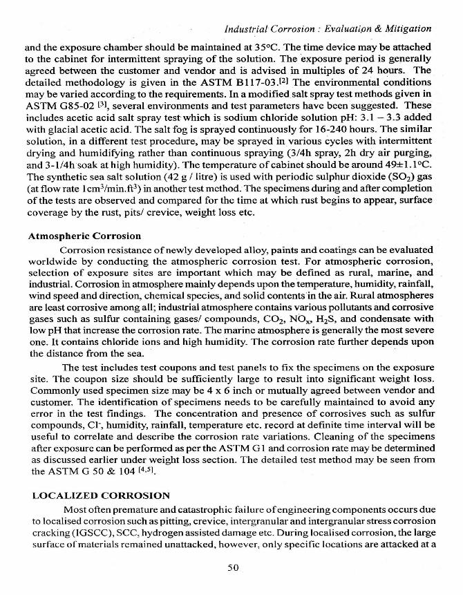
The temperature of solution increases with etching cycles that should be restricted below
500C. Fresh solution is preferred for every etching cycle. Post etch structures are categorizedas step , dual, and ditch as shown in Fig 1. These correspond to no grain boundary attack
(only steps are visible); slight or discontinuous grain boundary attack and continuous ditching
of grain boundaries. The material showing step structure is acceptable or free from IGC for
service and does not require testing by other methods . Stainless steels which contain lowcarbon or stabilized types are tested after sensitization at 675°C) for about 1 hour.
Ferric Sulfate-50% Sulfuric Acid Test (Streicher Test)
The specimens which show non-acceptable etch structure (from oxalic acid etching)are subjected to this test. This test is a quantitative measure of the relative performance ofthe material based on mass-loss determinations . The 50% sulphuric acid solution may beprepared by slowly adding -236 ml H2SO4 (98% by wt.) to 400 ml distilled water. 25 g ofFe2(SO4)3 is added to the-sulphuric acid solution and dissolved by heating. The test specimenmay be prepared by polishing on coarse grit emery papers (such as 80 or 120) followed bydegreasing. Overheating during polishing or grinding should be avoided. The sharp edgesshould be removed before subjecting them for tests . Specimen area and weight should bemeasured prior to putting them for the test. The solution is boiled in an Erlenmeyer flaskwith proper condensing (of vapours) arrangement. Test coupon may be placed in the solutionafter boiling starts . The boiling may be continued for 24 to 120h as desired by the customer.After the completion of the test, remove the specimen from the flask and rinse in water, dryand clean with acetone . Weigh the specimen and note down the final weight; calculate thedifference between the initial and final weight - The corrosion rates may be determined inmillimetres of penetration per month , as follows:
Corrosion rate (millimeter per month) _ (7290 x W)/(A x t x d)
Where: t = time of exposure, h, A = area, cm2W = weight loss , g, and d= density, g/cm3(For steels , d = 7.9 g/cm3, for chromium-nickel-molybdenum steels , d = 8.00 g/cm3)
Dual
Fig. I: Microstructures after electrolytic oxalic acid
53

Industrial Corrosion : Evaluation & Mitigation
Nitric Acid Test (Huey Test)
Boiling nitric acid is a strongly oxidizing environment to detect the chromiumdepleted regions as well as intermetallic precipitations, like sigma phase in the stainlesssteels. The state of the specimens should possibly be close to the one being used in service.It may be polished up to 80 or 120 grit emery paper. The edges evolved during cuttingshould be repolished. The overheating of specimen during preparation needs to be prevented.The degreased and polished specimens are boiled in a 1L Erlenmeyer flask containing 65%nitric acid with condenser. Volume of the solution for the test should be at least 20ml/cm2.Specimen shall be placed after boiling starts. After completion of each period, specimensare cleaned and weighed after drying. The corrosion rate during each boiling period iscalculated from the difference of weight of the specimens before and after the test and byusing a formula described earlier. This test also may be able to indicate the right heattreatment and sensitisation state of the specimens. Customer can decide and draw a line foraccepting the materials depending on corrosion rate.
Copper-Copper Sulphate 16% Sulphuric Acid Test (Strauss Test)
This procedure is conducted to determine the susceptibility of austenitic stainless
steel to intergranular attack associated with the precipitation of chromium-rich carbides.The test solution i.e. copper sulfate-16% sulphuric acid solution may be prepared bydissolving I OOg copper sulphate in distilled water in a 1000 ml flask. Add 100 ml of sulphuricacid to it and then dilute further with distilled water to 1000 ml. Place the solution in
Erlenmeyer flask containing Allhin condenser. Sufficient quantity of electrolytic grade copper
shots or grindings should be used along with the solution (8 ml/cm2). The galvanic couplingbetween the copper shots and test specimen must be assured. The specimen size may bespecified by the customers. Also the possible dimensions of rod, plate or tube are described
in ASTM A262-Practice E. After surface finishing followed by boiling in the Erlenmeyerflask containing above solution for 24 - 72 h, samples need to be rinsed and cleaned ifcopper is deposited on the specimen surface. The specimen is then subjected to bending
through 180° over a mandrel. In case of weld materials, the HAZ shall lies in the centre ofthe bend. The bent location shall be examined under low magnification (5-20X) where theappearance of fissures or cracks indicates the presence of intergranular corrosion attack asillustrated in Fig 2. For better clarity the same region may be viewed under highermagnifications. Crack length and depth may be evaluated and recorded.
Fig. 2 : Surface topographical features after the boiling and bend tests(A) appearance of IGC fissures (B) sample passed during the test
54
Industrial Corrosion : Evaluation & Mitigation
Copper-Copper Sulphate 50% Sulphuric Acid Test (Modified Strauss test)
This procedure is based on the relative weight loss of specimen subjected to boilingin copper-copper sulfate-50% sulphuric acid test . The solution may be prepared by adding236 ml sulphuric acid slowly to 400 ml distilled water and then 72 g of copper sulphate inthe Erlenmeyer flask. Place the copper shots/ chips in the flask. Clean and weigh the specimenbefore putting them in boiling copper sulfate-50% sulphuric acid solution. After 24-72hours of boiling, the specimens are removed and cleaned for any oxide or copper depositionon specimens followed by weighing . Determining the weight- loss and corrosion rate can becalculated by using formula mentioned above.
Stress Corrosion Cracking (SCC)
SCC is cracking of materials in the presence of tensile stresses (residual oroperational) in cracking prone environment. The SCC prone environments includinghydrogen can cause material to fail at stresses much below the yield or design stress. Crackmay propagate along the grain boundary, (intergranular stress corrosion cracking) or acrossthe boundary (transgranular cracking). Significant numbers of test method have beendeveloped to evaluate the stress corrosion cracking resistance of engineering materials.The test methods are broadly categorized as constant strain , static loading, and dynamicloading . Specimens may be smooth , notched or pre-cracked, based on fracture mechanicsprinciples . Constant-deformation (strain) tests are conducted by using widely knowngeometries of the specimen such as C-ring , O-ring, bent-beam and U-bend.19-13] In all thebent specimens , state of stress is much more complex than in tensile specimen where it isalmost uniform throughout the cross section . The maximum tensile stress zone in the bentspecimen is at convex surface and reduces to zero at neutral axis . This becomes compressiveand maximum at the concave surface and therefore 50% of surface is under tension and restunder compression. The crack initiation time and propagation rates are observed undervarious environmental and metallurgical conditions.
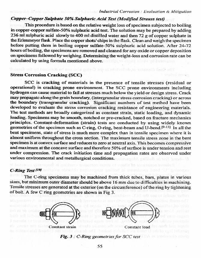
C-Ring Test 1101
The C-ring specimens may be machined from thick tubes, bars, plates in varioussizes , but minimum outer diameter should be above 16 mm due to difficulties in machining.Tensile stresses are generated at the exterior (on the circumference) of the ring by tighteningof bolt. A few C ring geometries are shown in Fig 3.
Constant strain Constant load
Fig. 3: C-Ring geometriesfor SCC test
55
Industrial Corrosion : Evaluation & Mitigation
Tensile stresses on the surface applied by the deformation loading are controlled byrestricting the strain with in the elastic range. The stresses on circumferential and transversesections can be accurately calculated and controlled using following formula
6C = E / (1- g2) . (EC + JET) and
(YT = E / (1- g2). (FT + g8C)
where E = Young modulus of elasticity, g= Poisson's ratio, EE = circumferentialstrain and ET = transverse strain. The circumferential and transverse strain can bemeasured by strain gages or micrometers.
The final diameter or deflection in the C-ring also can be obtained by the formulagiven below
ODF=OD-A
Where A = ficD2/4EtZ
ODF = final outside diameter (mm), OD= outside diameter before stressing (mm),.desired stress (MPa) within the proportion limit (elastic range), A = changes in the OD
to give desired stresses, t = wall thickness (mm) mean diameter D = OD-t, E = elasticmodulus (MPa), Z = a correction factor for curved beams.
The C-ring typically is under constant-strain till the crack initiate, however, by placinga calibrated spring on the bolt, a constant load can be applied to it. Details for fabricating Cring is given in ASTM G 3.8.
Similar to the C-ring, bent beams are another kind of geometry in severalconfigurations such as two points, three point and four point bent beam. Tensile stress onthe convex side is below the elastic limit and may be calculated precisely. h 11
U -bend Test in Boiling Magnesium Chloride Solution [12,131
Relative resistance of alloys to stress corrosion cracking is frequently assessed by
exposing `U' bend specimens in boiling magnesium chloride solution. This method isspecifically useful for all alloys (sufficiently ductile) susceptible to chloride related stresscorrosion cracking and not for chloride-free SCC. The bent area contains large amount of
plastic and elastic stresses, though the stress conditions are not precisely known. This methodmay not be suitable when the effect of small stresses on SCC is the main objective but is
rather useful to see the SCC resistance of one alloy in different metallurgical conditions.The crack initiation time and growth rate is observed during the experiment. A rectangular
strip of sufficient thickness is bent in `U' shape by about 1800 around a predetermined.
radius. Slow straining in single stage generally by using tensile testing machine or in twostages may be used. The single stage stressing is more accurate and also useful for thicksections unlike two stage bending. In two stage bending, specimen is stressed to almost U
shape and then released to eliminate the tensile elastic strain. To maintain the stress, the
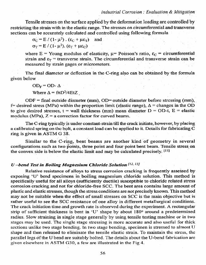
parallel legs of the U bend are suitably bolted. The details about the U-bend fabrication aregiven elsewhere in ASTM G30, a few are illustrated in the Fig 4.
56
Industrial Corrosion : Evaluation & Mitigation
The test environment i.e. magnesium chloride (MgC12.6H20) solution is preparedsuch that it boils at -155 .0 ±1.0°C (311 .0 t 1.8°F). To prepare about 400 ml of the testsolution, weigh 600 g of reagent grade MgC12 .6H20 and add this to Erlenmeyer flaskcontaining a thermometer along with 15 ml of reagent water. After the solution boils slowlyadd water at the top ofthe condenser to reduce the temperature to 155 °C (311 °F). A solutionof25 weight percent magnesium chloride is required for the trap if the test duration exceedsseven days without a solution change. Stressed specimens may also be tested for stresscorrosion cracking in alternate immersion method.1141
Welded bend
. Fig. 4: Various U-bend geometries
Slow Strain Rate test [15]
The constant strain by an external means is applied on the gage section of the tensileor precracked specimen. The low extension rate is such that it allows time to corrosionprocesses to occur on the surface and fast enough to produce cracking in reasonably short
time. The slow extension rate produces the strain rate in gage section in the range of 101 to
10-7/s. However, the selection of suitable strain rate depends upon the type of alloy and
environment. Too high a strain rate will result in ductile fracture and too low rate may
prevent corrosion by passive film repair and SCC may not occur. This method requires
tensile testing -machine with calibrated load cell, gripping devices for smooth transfer of
applied load to the specimen and fixtures, displacement gages, environment cell or autoclave
for high temperature test. The test specimen preparation shall be in accordance with the
ASTM E8. The dimensional measurement such as gage length and cross section are made
prior to the test. The data from SSR test can be analyzed for time-to-failure ratio, plastic
elongation ratio, % reduction in area. Each of these parameters shall be normalized with
respect to the controlled environment.
Polythionic Acid Cracking
Polythionic acid is found in petroleum refineries and strongly influences the IGSCCsusceptibility of stainless steels. Stainless steels that have undergone sensitization treatmentsare frequently tested in the polythionic acid solution, in laboratory, for determining theirsusceptibility to IGSCC. Sensitized stainless steels are fabricated in a U-bend as described
57
Industrial Corrosion : Evaluation & Mitigation
earlier and immersed in the polythionic acid. The initiation of cracking and crack growthrate can be monitored with time of exposure. The polythionic acid is prepared by bubblingHZS gas through the sulfurous acid (H3SO3). The latter may be produced by bubbling SO2gas in distilled water, in accordance with the ASTM specification.[161
Hydrogen Induced Cracking (HIC) and Sulfide Stress Cracking (SSC) [171
Hydrogen damage is common failure mode in the pressure vessels and pipe line
steels exposed to wet sour environments such as in petroleum and natural gas industries.Hydrogen induced cracking occurs in low strength steels (<550 MPa) during wet hydrogen
sulfide (H2S) exposure. While SSC occurs in the high strength and or/high hardness steels
under the influence of external tensile stress and is caused by absorption of hydrogen from
wet H2S corrosion. HIC is due to the internal pressure build up by accumulated hydrogen(molecular) even in non-stressed specimens. The HIC test method involves exposure of
unstressed steel coupons to either 5% sodium chloride solution (NaCI) + 0.5 % acetic acid
solution (CH3COOH) or an artificial sea water solution. The test solution shall be deaeratedwith argon or nitrogen and then saturated with H2S gas. The detailed test method is availablein NACE TM-02-84. It compares the degree of susceptibility to HIC in each section fordifferent steels. It is represented in terms of crack length ratio (CLR), crack thickness ratio(CTR) and crack sensitivity ratio (CSR). The CLR is the sum of crack length of each arraydivided by the width of the section and multiplied by 100%. The CTR is the sum of thecrack thickness of each crack array divided by the thickness of the section and multipliedby 100%. The CSR is the sum of the effective cracked area of each crack array divided bythe area of the section and multiplied by 100%. The standard does not specify pass or failvalues. However, some companies used maximum CLR -'15% to qualify the steels for wetsour line pipe applications.
Concrete Corrosion
Corrosion of concrete rebar is primarily influenced by the various admixtures usedand chloride ingress from the environment or concrete constituents. Concrete rebar can betested for corrosion in laboratory as well as in the atmosphere.[18,191 For this, two rebar ofcertain sizes are placed in the mould which then is filled with concrete and admixtureswhich are being tested for corrosive effects. A control concrete rebar shall also be preparedfrom the concrete not containing the admixtures. Concrete beam are prepared as per thestandard ASTM C192/192M. After curing and drying the specimen in a moist room, anartificial pond is created with one surface of the concrete as the pond base . This ensuresthat one of the rebar is wet while the other is relatively dry. This pond is maintained for twoweeks in 3% NaCI solution at 23+/-3°C; the solution volume should be around 400 ml anddepth 40 mm. The solution is then sucked off and the voltage across the 100-ohm resistorbetween the rebar is measured. By cyclically ponding with 3% sodium chloride, the chloridepermeates through the concrete and the upper bar begins to corrode, with the bottom barsacting as cathodes. The current can be measured as I = V/ 100.
Also measure the corrosion potential of bars against reference electrode and monitorthe current every week for some time. Visual observations of the bars on test completionwill reveal percentage of corroded area and may be recorded.
58
Industrial Corrosion Evaluation & Mitigation
ELECTROCHEMICAL METHODOLOGIES
Electrochemical tests methods need a device for measuring and applying accuratecurrent and potentials (a Potentiostat/ Galvanostat), an electrochemical cell containingreference electrode (e.g. saturated calomel, silver-silver chloride), a counter electrode (suchas platinum or graphite) and working electrode ( a test specimen) along with experimentalsolution. Reference electrode measures the potential of the specimen-solution interfaceand the counter electrode facilitate electrochemical current flow. Electrochemical tests forcorrosion resistance evaluation are preferred due to short experimental time, and can providereal time (time-corrosion) data on a single specimen. With the advent of advancedinstrumentation, these methods became even easier and attractive. Electrochemical methodsare specifically useful for studying the mechanism of corrosion in the different current-potential region corresponding to various environmental situations. Various electrochemicaltechniques are available to evaluate the different forms of corrosion such as general, pitting,crevice, IGC, galvanic etc. Regardless of the technique, each relies on the same basicprinciples; in each test, a metallic coupon in an electrolyte is subjected to the application ofcurrent or potential from an external source (Potentiostat/ Galvanostat). This current/potentialstimulates the surface corrosion reactions. The voltage or current response of the corrodingcoupon is recorded and correlated with the current or potential applied. In either case,the resultant current is representative of the rate determining mass transfer or chargetransfer rate.
Corrosion Rate Determination
For general corrosion where corrosion rate is of concern, polarization resistance,Tafel extrapolation, and electrochemical impedance methods are employed. [20-231
Tafel Extrapolation
A relationship is obtained between log current density and applied potential. Aperturbation off 250mV is applied with respect to open circuit potential (E,,0) in cathodic
as well as anodic direction and the resulting current is recorded by potentiostat. However,such a large over potential may be damaging to the surface particularly during anodic
polarization in which a metal surface gets changed due to corrosion/ passivation processes.
The cathodic polarization is therefore more realistic and surface damage is relatively small.
Corrosion current (i^0 ) may be determined by extrapolating the straight linear region fromeither cathodic or anodic curve to the open circuit potential as shown in the Fig 5. For
better accuracy the linear region must be minimum an order of magnitude of current.
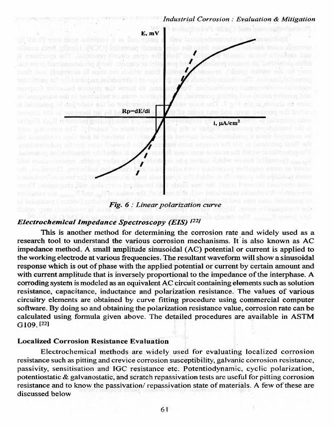
Linear Polarization Resistance (LPR) X20.211
The Tafel extrapolation method is dependent on activation controlled electrochemical
reactions. For concentration controlled reactions, however there may be deviations from
linearity for large overpotentials. The LPR technique exploits the linearity that appears
within 5 to 10 mV of the corrosion potential as described by the Stern and Geary, shownschematically in Fig 6. The potential is scanned at a constant rate (0.6V/h) with a short
potential range. The slope of the resultant current versus potential plot gives the polarization
resistance (inverse of corrosion current density).
59

Industrial Corrosion : Evaluation & Mitigation
icorr = Pa Pc/2.3 Rp (1a + Rc)
where icon is current density, {3a and (3c are anodic and cathodic slope , Rp is polarization
resistance . After obtaining the corrosion current density or the polarization resistance values,a corrosion rate can be calculated by formula given in ASTM G 102.
Corrosion rate = (K x icon x EW)/(D)
Where
Corrosion rate = mm/y
icorr = corrosion current density, µA/cm2
K =3.27x 10⁻³, mm g/mA cm yr,
EW = equivalent weight (atomic weight of the base alloying element/number ofelectrons involved in the oxidation process),
D= Material density, g/ cm3
+ 0.25 -I
^s
d0C,
0z
wEcorr
I-- Anodic
... .....................
.-Cathodic
- 0.25 -i-10-6 1o-4 10-2
Current density , (µA/cm2)
Fig. S : Tafel extrapolation
I
10
60
Industrial Corrosion : Evaluation & Mitigation
Fig. 6: Linear polarization curve
Electrochemical Impedance Spectroscopy (EIS) 1221
This is another method for determining the corrosion rate and widely used as aresearch tool to understand the various corrosion mechanisms. It is also known as ACimpedance method. A small amplitude sinusoidal (AC) potential or current is applied tothe working electrode at various frequencies. The resultant waveform will show a sinusoidalresponse which is out of phase with the applied potential or current by certain amount andwith current amplitude that is inversely proportional to the impedance of the interphase. Acorroding system is modeled as an equivalent AC circuit containing elements such as solutionresistance, capacitance, inductance and polarization resistance. The values of variouscircuitry elements are obtained by curve fitting procedure using commercial computersoftware. By doing so and obtaining the polarization resistance value, corrosion rate can becalculated using formula given above. The detailed procedures are available in ASTMG 109. [22]
Localized Corrosion Resistance Evaluation
Electrochemical methods are widely used for evaluating localized corrosion
resistance such as pitting and crevice corrosion susceptibility, galvanic corrosion resistance,
passivity, sensitisation and IGC resistance etc. Potentiodynamic, cyclic polarization,potentiostatic & galvanostatic, and scratch repassivation tests are useful for pitting corrosionresistance and to know the passivation/ repassivation state of materials. A few of these are
discussed below
61

Industrial Corrosion : Evaluation & Mitigation
Potentiodynamic and Cyclic Polarization 121,241
Specimen in a electrochemical cell is polarized at a constant scan rate (O.6V/h)towards more anodic direction from the open circuit potential (OCP). Ideally, both anodicand cathodic scans should be initiated from the open circuit potential. The specimen isoften polarized till certain predetermined potential or current. Such predetermined potentialmay be the vertex (peak), reverse (potential from which the scan is reversed) and finalpotential /current. The choice depends upon the type of information required for the particularmaterial-environment combination. For instance, to know the passive behavior (currentand passive zone) and pitting potential, the specimen must be polarized in the transpassivezone as shown in the Fig 7. The zone which is independent of the variation in potential iscalled the passive zone and end point of this zone followed by an increase in the currentwith potential is characterized by breakdown of passive film (pitting potential Ep;t). Higheris the breakdown potential, higher is the pitting resistance of material. The scanning maybe reversed once a predetermined current or potential is arrived at and then continued tillthe final potential or till the reverse scan intersects the forward scan (cyclic polarization).The potential at which the reverse scan meet forward scan is called the repassivation potential,Eprateet (potential below which active pits repassivate). In other words, repassivation willoccur at more negative potentials even after localized corrosion initiation. Therefore, themore positive the potential at which the hysteresis loop is completed (or reverse/backwardscan intersect forward scan), the less likely that localized corrosion will propagate. Thereare certain drawbacks associated with this method; the value of E,t and Ep,-df"t are sensitiveto potential scan rate and the value of Eprotect vary with the polarizing (vertex) potential inthe transpassive zone. Higher vertex (potential from which scan is reversed) may resultinto lower Epr4,tect• The details about conducting this test is given in ASTM G 61.[2 1, 241
Epit
E Pratt'
r.Lo
1
rrc I
Fig. 7 : Schematic cyclic anodic polarization curve
62
Industrial Corrosion : Evaluation.;& Mitigation
Potentiostatic and Galvanostatic Methods
The sensitivity of scan rate in evaluating the localized corrosion resistance (usingcyclic potentiodynamic) may be overcome by potentiostatic methods. The Epit can beobtained by polarizing specimen at potentials above and below the, values of Eprot and Epitdetermined from the potentiostatic polarization. The initiation of pitting is indicated by theincrease in current with time. By conducting a series of current versus time curves at anincrement o€50 mV, the Epit is identified as lying between two potentials at which current-potential curve shows deviation from decreasing or constant trend. For Ep,.ot the pits areintentionally initiated at a potential higher than the Epit and then quickly shifted to belowthe Eprotect for current versus-time curve. The repassivation of pits will be indicated bydecrease in current with time (see ASTM F746 and ASTM G 100 for details). [25, 261
Evaluation of Sensitization
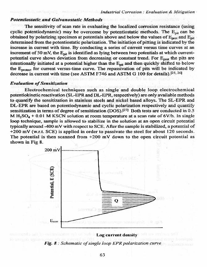
Electrochemical techniques such as single and double loop electrochemicalpotentiokinetic reactivation (SL-EPR and DL-EPR, respectively) are only available methodsto quantify the sensitization in stainless steels and nickel based alloys. The SL-EPR andDL-EPR are based on potentiodynamic and cyclic polarization respectively and quantifysensitization in terms of degree of sensitization (DOS).1271 Both tests are conducted in 0.5M H2SO4 + 0.01 M KSCN solution at room temperature at a scan rate of 6V/h. In singleloop technique, sample is allowed to stabilize in the solution at an open circuit potentialtypically around -400 mV with respect to SCE. After the sample is stabilized, a potential of+200 mV (w.r.t. SCE) is applied in order to passivate the steel for about 120 seconds.The potential is then scanned from +200 mV down to the open circuit potential asshown in Fig 8.
200 mV
EcoR
Log current density
Fig. 8 : Schematic of single loop EPR polarization curve
63
Industrial Corrosion : Evaluation & Mitigation
With decrease in potential, the sensitized grain boundaries will preferentially activatewhile the grain matrix remains passivated. The total anodic current or charge (Q) passed,during decreasing potential (reverse scan), is proportional to the grain boundary areaactivated. This is indicative of the degree of sensitization. The normalized charge (Pa) inunits of coulombs/cm2 is calculated using following equation:
Pa = Q/XwhereQ = charge measured on current integration measuring instrument (coulombs).Q is normalized for both specimen size and grain,X = AS [5.1 X 1 0-3 eO35G
AS = specimen area (cm2 ), andG = Grain Size at I OOX (in accordance with test method ASTM E 112).
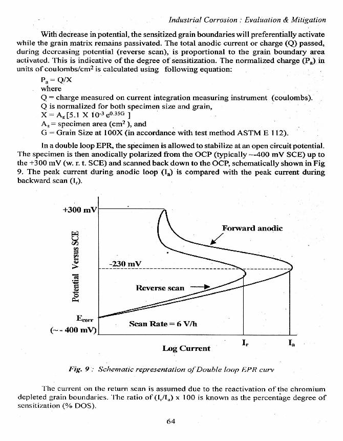
In a double loop EPR, the specimen is allowed to stabilize at an open circuit potential.The specimen is then anodically polarized from the OCP (typically --400 mV SCE) up tothe +300 mV (w. r. t. SCE) and scanned back down to the OCP, schematically shown in Fig9. The peak current during anodic loop (Ia) is compared with the peak current duringbackward scan (I,.).
Log CurrentI,.
Fig. 9 Schematic representation of Double loop EPR curv
Ia
The current on the return scan is assumed due to the reactivation of the chromiumdepleted grain boundaries . The ratio of (I,/Ia) x 100 is known as the percentage degree ofsensitization (% DOS).
64
Industrial Corrosion : Evaluation & Mitigation
Galvanic Corrosion
Galvanic corrosion needs a couple consisting two metals or alloys of interest. Thecouple should be in electrical contact of each other and connectivity may be checked beforeexposing them to desired environment. Electrical contact of the dissimilar metals should bechecked periodically. The connectivity between the dissimilar metals/ alloys can be madeby pressure contact, soldering or brazing, spot welding, bolting etc. The corrosion at thejoint locations would however be inevitable which, in turn, may affect the electrical contactbetween the two candidates of the couple. To prevent the corrosion at such joints, coatingmay be a useful solution. The couple should not be in electrical contact with the test chamberor container. The corrosion or corrosion rate of the couple may be evaluated which wouldindicate the corrosion ofthe anodic component ofthe couple. The cathodic member, however,will be protected cathodically. The exposure time for galvanic corrosion test should be ofsufficient length so that the corrosion processes have reached steady state and intermediatevariations in corrosion reaction would not underestimate or overestimate the corrosionrate. More detail on galvanic corrosion testing in electrolytes is given in ASTM G 711281
Hydrogen Transport, Diffusion, and Permeation
Among the different form of degradations, hydrogen damage such as hydrogenembrittlement, hydrogen induced cracking, blistering are quite common to cause prematurefailures of industrial components. Hydrogen entry into the material can occur during melting,electroplating, and in service due to corrosion. The degradation due to hydrogen may varywith composition, microstructure, and stress levels of the material in service. Theconcentration of hydrogen traps in the material determines the level or degree to which thematerial can suffer. The concentration is a function of diffusion coefficient, which can bedetermined experimentally by different methods such as: electrochemical method, sub-surface micro hardness profiling, nuclear reaction analysis and nanoindentationmeasurements. The method that has greater acceptance in determining the diffusion inmaterials is the hydrogen permeation technique. This method can help to recognize howalloy contents and crystal defects affect the diffusion process. In solid solution, hydrogenat low concentration in the material does not change the mechanical properties, exceptduring the application of load. As a consequence of loading , dislocations are generatedwith the possibility of becoming hydrogen traps (as these tend to migrate towards areas ofhigh strain field). The transported hydrogen can eventually cause high local pressure therebyreducing the stress intensity factor and culminating in brittle fracture. For hydrogenpermeation experiments, a two-cell system based on the Devanathan and Stachurskitechnique with some modifications is used.
The hydrogen charging of the sample on the left side (cathodic) cell is controlledpotentiostatically or galvanostatically by a DC power source. Electrolyte used in the chargingcell may be 0.1 M H2SO4 (for steel). Poison such as Na2HAsO4.7H2O may be used toincrease the hydrogen entry rate and subsequent permeation. The exit side (anodic cell) iscontrolled by potentiostat in different modes such as potentiostatic, galvanostatic,potentiodynamic etc. The environment in the exit or anodic side, should be such that highanodic or background current may be minimized (for example 0.1 M NaOH for steels).
6 1;
Industrial Corrosion : Evaluation & Mitigation
Calculations for such as steady state permeation current, diffusion coefficient etc may be
performed as per the ASTM G148 and ISO: 17081. [29,301
ONLINE CORROSION MONITORING
A few corrosion test methods have been automated to portable corrosion probessuch as LPR (linear polarization resistance ), ER (electrical resistance probes which can beused to monitor the corrosion rates in-situ as described in ASTM G96J311 Such probes arewidely used in the petrochemical industries, cooling water system, refineries etc. Thedevelopments have been made to provide online real-time monitoring techniques andprogress on corrosion damage can now be seen in a very short interval (within minutes).These developments could reduce the time and efforts to obtain corrosion data. The LPRprobes are based on the linear polarization resistance as also mentioned in the earlier sections.The electrical resistance probes are based on the principle that the decreasing cross sectionthickness will increase the electrical resistance represented as
R = pl/A, where r is resistivity, I is length of conductor,and A is area of cross section.
REFERENCES:
1. ASTM G I "Practice for Preparing, Cleaning, and Evaluating Corrosion TestSpecimens
2. ASTM B117: Practice for operating Salt Spray (fog) Apparatus
3. ASTM G85 :Practice or Modified salt spray (fog) test
4. ASTMG50-76(2003) Standard Practice for Conducting Atmospheric Corrosion
Tests on Metals
5. ASTM G104: test method for assessing galvanic corrosion caused by the
atmosphere.
6. ASTM: G 48 - 03 Standard test methods for pitting and crevice corrosion resistance
of stainless Steels and related alloys by use of ferric chloride Solution.
7. ASTM G 46 - 94 Examination and evaluation ofpitting corrosion
8. ASTM 262 A-F: Standard practices for Detecting Susceptibility to Intergranular
Attack in Austenitic Stainless Steels
9. ASTM E8: Test method or tension testing of the metallic materials
10. ASTM G38: Making and using C-ring stress corrosion test specimens
11. ASTM G39: Practice for preparation and use of bent beam stress corrosion test
specimen
12. ASTM G30: Making the U bend stress corrosion test specimen
13. ASTMG36: Practice for performing stress corrosion cracking test in a boiling
magnesium chloride solution
66
Industrial Corrosion : Evaluation & Mitigation
14.. ASTMG44: Practice for evaluating stress corrosion cracking resistance of metals
and alloys by alternate immersion in 3.5 % NaCl solution
15. ASTM G129: Standard practice for slow strain rate testing to evaluate thesusceptibility of metallic materials to environmental assisted cracking.
16. ASTM GG35-88 Standard practice for determining the susceptibility of stainlesssteels and related nickel-chromium-iron alloys to stress corrosion cracking inpolythionic acid.
17. NACE TM-0284: Evaluation ofpipe line and pressure vessel steels for resistanceto hydrogen induced cracking.
18. ASTM C192/192M `Practice for making and curing concrete test specimens inthe laboratory
19. ASTM GI 09 `Determining the effects of chemical admixtures on the corrosion ofembedded steel reinforcement in concrete exposed to chloride environments.
20. ASTM G 5, "Standard reference test method for making potentiostatic andpotentiodynamic anodic polarization, measurements
21. ASTM G 59, Practice for Conducting Potentiodynamic Polarization ResistanceMeasurements.
22. ASTM G 106: Practice for Verification ofAlgorithm and Equipment forElectrochemical Impedance Measurements.
23. ASTM G102: Practice for Calculation of Corrosion Rates and Related Informationfrom Electrochemical Measurements.
24. ASTM G 61 describes a procedure for conduction cyclic potentiodynamic pola-rization measurements to determine relative susceptibility to localized corrosion.
25. ASTM F 746: Test method for Pitting or Crevice Corrosion of Metallic SurgicalImplant Materials
26. ASTM G 100: Method of Conducting Cyclic Galvanostaircase Polarization.
27. ASTM G 108: Standard test method for electrochemicalpotentiokinetic reactivation(EPR) for detecting sensitization of AISI type 304 and 304L stainless steels.
28. ASTM G 71 [27], Guide for Conducting and Evaluating Galvanic Corrosion Tests
in Electrolytes.
29. ISO 17081:2004 Method of measurement of hydrogen permeation and determi-
nation of hydrogen uptake and transport in metals by an electrochemical technique
30. ASTM 148-97: Evaluation of hydrogen uptake, permeation and transport in metals
by an electrochemical technique.
31. ASTM G96 Practice of online monitoring of corrosion in pant equipment
(electrochemical and electrical resistance methods)
67