
Circuit Properties of Zero-Voltage-Transition PWM Converters
Upload
westenglandCategory
view
0download
0
Int. J. Power and Energy Conversion, Vol. 2, No. 4, 2011 289
Copyright © 2011 Inderscience Enterprises Ltd.
Direct power control of the PWM rectifier using sliding mode control
Said Barkat Laboratoire d’Analyse des Signaux et Systèmes (LASS), Université de M’sila, BP. 166, Rue Ichbilia, 28000 M’sila, Algérie, Algeria E-mail: s_barkat @yahoo.fr
Abdelhalim Tlemçani Laboratoire de Recherche en Electrotechnique et en Automatique (LREA), Université Docteur Yahia Farès de Médéa, Quartier Aind’heb 26000, Médéa, Algérie, Algeria E-mail: [email protected]
Hassan Nouri* Power Systems, Electronics and Control Research Group, University of the West of England (UWE Bristol), Frenchay Campus, Coldharbour Lane, Bristol, UK E-mail: [email protected] *Corresponding author
Abstract: This paper presents the analysis and design of the direct power control of a boost PWM rectifier based on sliding mode control. In the aim to improve control performance of the rectifier, the proposed approach combines the merits of sliding mode control, direct power control and space vector modulation. The resulting control scheme is able to drive the output dc voltage to the desired value while keeping a sinusoidal input phase control with a unity power factor. The feasibility and effectiveness of the considered control structure has been examined by computer simulations.
Keywords: PWM rectifier; space vector modulation; direct power control; sliding mode control.
Reference to this paper should be made as follows: Barkat, S., Tlemçani, A. and Nouri, H. (2011) ‘Direct power control of the PWM rectifier using sliding mode control’, Int. J. Power and Energy Conversion, Vol. 2, No. 4, pp.289–306.
Biographical notes: Said Barkat received his Engineer, Magister and Doctorate degrees, all in Electrical Engineering, from the Polytechnic National Institute of Algiers in 1994, 1997 and 2008 respectively. In 2000, he joined the Department of Electrical Engineering, University of M’sila. His current research interests are in the field of power electronics and electric machines, advanced control theory and applications.
290 S. Barkat et al.
Abdelhalim Tlemçani received his Engineering degree and MSc in Power Electronics from the National Polytechnic School of Algiers (ENP), Algeria, in 1997 and 1999, respectively. He received his Doctorate degree in Electrical Engineering from ENP in 2007. Since 2002 he has held teaching and research positions in the Department of Electrical Engineering, UYFM, where he is currently an Associate Professor. He is the Director of Control and Power Electronics Research Group. His research interests are in the field of power electronics, electrical drives, robust and non-linear control and fuzzy systems.
Hassan Nouri received his BSc from the University of Nottingham, Nottingham, UK; MSc from the University of Strathclyde, Glasgow, UK; and PhD from the University of Plymouth, Plymouth, UK, all in Electrical and Electronic Engineering. He is a Reader in electrical power and energy at UWE Bristol, UK. He was the Chairman of the European Electromagnetic User Group EEUG 2004–2010 and currently the Director of the Power Systems, Electronics and Control Research Group at the University of the West of England, Bristol, UK. His research interests include the analysis of power systems, electric arc phenomena and the application of power electronics, neural networks, fuzzy logic and FE in power engineering. He is a member of the IEEE Power Engineering Society and various international power engineering committees.
1 Introduction
Many industrial applications, such as adjustable speed drives, dc switching power supplies and uninterruptible power supply systems, require rectifiers as front-end converters to interface with the utility grid. For some time, the uncontrollable diode rectifier and line commuted phase controlled thyristor bridge have been the most commonly used in ac to dc conversion. Although simple and low cost, such converters produce distorted input currents with poor power factors. Moreover, the harmonic currents injected into the ac voltage supply causes voltage distortion, electromagnetic inference, equipment overheating and malfunction of sensitive electric equipment (Subjak and Mcquilkin, 1990). The significance of this problem has led to development of various international standards that specify limits on the magnitudes of harmonic currents and harmonic distortion (IEEE STD 519, 1992; IEC 61000-3-4, 1998).
An effective method to maintain good power quality and reduce harmonic problems is to utilise active rectifiers. PWM rectifiers have increasingly been employed in recent years owing to their advanced features, including input sinusoidal current, controllable input power factor, bidirectional power flow and high quality dc output voltage.
Over the past few years, there have been extensive studies on control algorithms for PWM rectifiers. Maybe the most popular control scheme is the well-known voltage oriented control (VOC) (Kwon et al., 1999). It based on synchronous current controllers working in dq-coordinates. This method presents good dynamic and static behaviour; however, its performance depends on the quality of the applied current control strategy (Kazmierkowski and Malesani, 1998).
As an alternative to the VOC method, the direct power control (DPC) of the PWM rectifier is proposed by Manninen (1995) and Noguchi et al. (1998) as an expansion of the direct torque control (DTC). The basic idea is to control instantaneous active and reactive powers within the desired error bands, by properly selecting the rectifier

Direct power control of the PWM rectifier using sliding mode control 291
switching states. In a conventional DPC scheme, no internal control loops, no PWM modulator and no coordinate transformations are required. However, the switching frequency varies with operating conditions and for accurate control the sampling frequency must be higher. In order to overcome these problems, a solution based on space vector modulation (SVM) has been proposed (Malinowski et al., 2004). This method requires a coordinate transformation and the quality of control depends on the quality of the used controllers.
On the other hand, several non-linear control algorithms have found application in PWM rectifier control over the last years. The proposed control strategies include among others Lyapunov-based control (Komurcugil and Kukrer, 1998), feedback linearisation control (Jung et al., 1999; Lee et al., 2000), passivity-based control (Perez et al., 2004), fuzzy logic control (Jasinski et al., 2002; Cecati, et al., 2003, 2005) and sliding mode control (Ryvkin et al., 2008; Shtessel et al., 2008).
Due to its robustness properties, sliding mode control (SMC) is one of the effective and suitable methods for the control of the wide class of linear and non-linear systems. For this reason, this paper now presents a new approach for control of PWM rectifiers based on the combination of the well known DPC advantages with those of SMC; giving DPC-SMC control scheme.
This paper is outlined as follows: a presentation of the used PWM rectifier model is given in Section 2. In Section 3, the conventional DPC-PI based on the virtual flux concept is presented. Section 4 introduces the proposed control scheme and the formulation of the control task. Simulation results that illustrate the properties of the suggested DPC-SMC are presented in Sections 5 and 6. Finally, the conclusion is presented in Section 7.
2 PWM rectifier modelling
The boost PWM rectifier configuration is shown schematically in Figure 1. The bridge circuit is constructed of six controllable power switches and anti-parallel diodes. The rectifier ac side is connected to power network voltages ( 1,2,3)ie i = using three inductors L with loss resistance R.
Figure 1 Schematic diagram of PWM rectifier
LR
2e
1i
C dcv
1T 2T3T
1D 2D3D
1T′2T′ 3T′
1D′ 2D′ 3D′
R
R
r2uL
L
1e
3e2i
3ir3u
r1uLR
rI
∼
∼
∼
It is assumed that the input ac voltage is a balanced three-phase supply as follows:
2( ) sin ( 1) ; 1,2,33i me t E t i iπω⎡ ⎤= − − =⎢ ⎥⎣ ⎦
(1)

292 S. Barkat et al.
where Em and ω are the amplitude of the phase voltage and the angular frequency respectively.
According to Kirchhoff’s voltage low, the dynamic equations of the ac line currents ( 1,2,3)ii i = can be deduced as below:
; 1, 2,3ii i ri
diL Ri e u i
dt= − + − = (2)
With uri is the rectifier input phase voltage. On the other hand, assuming RL as the dc load, the voltage equation on dc side will
be:
1 1 2 2 3 3dc dc
L
dv vC S i S i S i
dt R= + + − (3)
where C is the capacitance of the output capacitor and Si is the switching function of ith lag of the converter.
To simplify the design and analysis, it is very convenient to transform the three-phase model into a stationary reference frame (αβ) Thus, the mathematical model of the PWM rectifier under (αβ) coordinates can be written as follows:
r
r
dc dc
L
diL Ri e u
dtdi
L Ri e udtdv v
C S i S idt R
αα α α
ββ β β
α α β β
= − + −
= − + −
= + −
(4)
This model will be used for system analysis, design of control laws and computer simulations.
3 Conventional DPC-PI
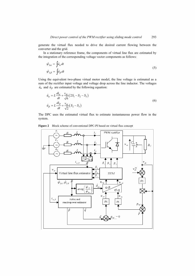
In the control scheme depicted in Figure 2, the reactive power reference is set to zero for unity power factor consideration and the active power reference is delivered from the PI-DC voltage controller. The errors between the references and their estimated values are delivered to PI controllers. The output signals from PI controllers after transformation are used as switching signals for a space-vector modulation (SVM).
3.1 Virtual line flux estimator
The concept of the virtual line flux for power estimation is introduced by Malnowski et al. (2001). Compared to the voltage-based power estimation, this approach has the advantage that estimation is simpler and a lower sampling time is needed (Malinowski et al., 2001).
The idea is based on a duality with the PWM inverter fed induction motor. The ac-side of the PWM rectifier is assumed as a virtual motor. Then, the estimated virtual line flux can be used in the control system. Therefore, the rectifier is controlled to
Direct power control of the PWM rectifier using sliding mode control 293
generate the virtual flux needed to drive the desired current flowing between the converter and the grid.
In a stationary reference frame, the components of virtual line flux are estimated by the integration of the corresponding voltage vector components as follows:
ˆ ˆ
ˆ ˆ
L
L
u dt
u dt
α α
β β
ψ
ψ
=
=
∫∫
(5)
Using the equivalent two-phase virtual motor model, the line voltage is estimated as a sum of the rectifier input voltage and voltage drop across the line inductor. The voltages uα and uβ are estimated by the following equation:
( )
( )
1 2 3
2 3
ˆ 26
ˆ2
dc
dc
di vu L S S S
dtdi v
u L S Sdt
αα
ββ
= + − −
= + − (6)
The DPC uses the estimated virtual flux to estimate instantaneous power flow in the system.
Figure 2 Block scheme of conventional DPC-PI based on virtual flux concept
294 S. Barkat et al.
3.2 Active and reactive power estimator
For sinusoidal and balanced line voltage and using information about line currents (iα and iβ) and the estimated virtual line flux components ( Lˆ αψ and Lˆ βψ ). The estimated active and reactive powers can be described by the following formulas (Malinowski et al., 2001):
( )( )
ˆ ˆˆ
ˆ ˆˆ
L L
L L
p i i
q i i
α β β α
α α β β
ω ψ ψ
ω ψ ψ
= −
= + (7)
Both power estimation equations are simple to calculate and do not require the computation of the current derivatives.
4 Proposed DPC-SMC
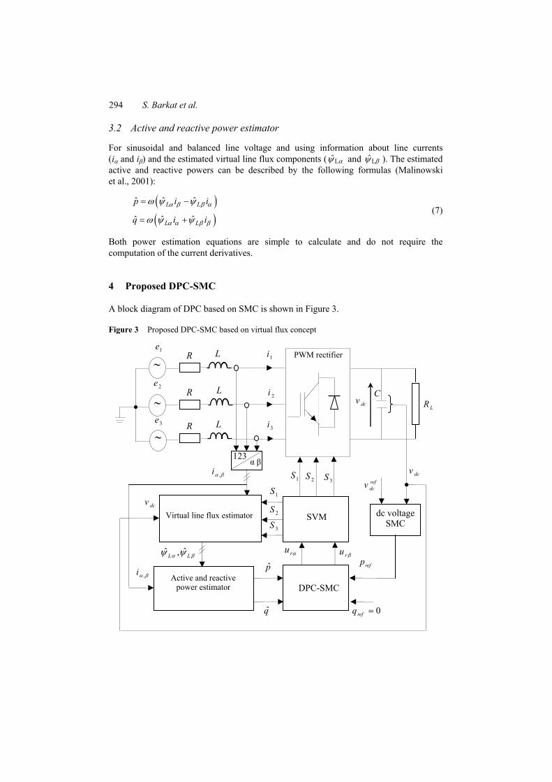
A block diagram of DPC based on SMC is shown in Figure 3.
Figure 3 Proposed DPC-SMC based on virtual flux concept
1i
refdcv
C
dcv
dcv
0refq =
123α β
Active and reactivepower estimator
ru βru α
LR
1e
2e
3e
R
R
R
L PWM rectifier
SVM
p
2i
3i
L
L
dcv
1S 2S 3S
1S
2S
3S
ˆ ˆ,L Lα βψ ψ
,iα β
∼
∼
∼
Virtual line flux estimator
,iα β
q
refp
DPC-SMC
dc voltage SMC
Direct power control of the PWM rectifier using sliding mode control 295
The outer loop contains a dc voltage sliding mode controller which produces the active power reference. The inner loop includes a sliding mode direct power controller which calculates the most appropriate input rectifier voltage vector to enforce the active and reactive powers to track their references. Hence, the bloc DPC-SMC provides the required rectifier voltage components for the space vector modulator, which generates pulses to control the rectifier.
One glance at the proposed control scheme shows that the dq-αβ transformation bloc is removed. In addition, when compared to the conventional control scheme one, the power regulators are merged into only one regulator.
4.1 Output dc voltage SMC
The non-linear controller based on SMC is known to be robust against parametric uncertainties and external disturbance (Utkin et al., 1999). The controller objective is to drive the plant state to the sliding surface and maintain it on the surface for all subsequent times (Slotine and Li, 1991).
4.1.1 Sliding surface design
The first phase is to construct a sliding surface so that the system restricted to it has the desired behaviour. Various forms of sliding surfaces are proposed in the literature. One way is to define the sliding surface as:
1
10
( ) ( ) ( )tnds t e t k e d
dtλ τ τ
−⎛ ⎞= + +⎜ ⎟⎝ ⎠ ∫ (8)
where e(t) is a tracking error, and λ and k1 are strictly positive constants. For output dc voltage tracking-problem, n is set to 1 and the sliding surface is
designed as follows:
( )1ref ref
dc dc dcdc dcs v v k v v dt= − + −∫ (9)
Its time derivative dcs is given by:
( )1ref refdcr
dc dcdc dcL
vIs v k v v
C R C= − + + − (10)
4.1.2 Control law synthesis The control objective is to elaborate a required control Ir law that forces the output vdc to follow the desired trajectory ref
dcv in the presence of parameter and disturbance uncertainties by using sliding mode concept. In order to achieve this goal, the load current is assumed to satisfy the following condition:
dc
L
vR
β≤ (11)
where β is an unknown positive constant. To ensure the control objective, the following law control is proposed:

296 S. Barkat et al.
( ) ( )1 2ˆ sgnref ref
r dc dc dcdc dcI C v k C v v k s sβ= + − + + (12)
where β is the estimate of the unknown constant β and k2 is a positive constant. The function sgn(.) denotes signum function defined as:
( )1, 0
0, 01, 0
dc
dc dc
dc
if ssgn s if s
if s
+ >⎧⎪= =⎨⎪− <⎩
(13)
The bound β is estimated on line by the law:
ˆdcs
Cηβ = (14)
where η is a positive constant. To reduce the undesirable chattering of SMC, the discontinuous part of the controller
is smoothed by introducing the saturation function given as follows:
( )sgn( )
dcdc
dc
dc dc
ssi s
sat ss si s
αα
α
⎧ ≤⎪= ⎨⎪ >⎩
(15)
where α > 0 is a smooth factor. The active power reference is calculated as:
ref dc rp v I= (16)
4.1.3 Stability analysis
Let us use the following Lyapunov function:
2 21 12 2dcV s β
η= + (17)
With ˆ.β β β= − The time derivative of V is given by:
1 ˆdc dcV s s ββ
η= − (18)
By substitution of the equation (10) in (18), it yields:
( )11 ˆref refdcr
dc dcdc dcL
vIV s v k v v
C R Cββ
η⎡ ⎤
= − + + − −⎢ ⎥⎣ ⎦
(19)
From the control law (12), the equation (19) becomes:
( )21 1ˆ ˆsgndc
dc dc dcL
vV s k s s
R Cβ ββ
η⎡ ⎤
= − + − −⎢ ⎥⎣ ⎦
(20)
Direct power control of the PWM rectifier using sliding mode control 297
By using condition (11), equation (20) can be written as below:
22
1 1ˆ ˆdc dc dcV k s s s
Cβ β ββ
η≤ − + − − (21)
The inequality (21) can be put in this form:
22
1 1 ˆdc dcV k s s
Cβ ββ
η≤ − + − (22)
By using the adaptation law (14), the equation (22) is reduced to: 2
2 dcV k s≤ − (23)
The inequality (23) shows that the sliding surface, consequently the tracking error, converges asymptotically towards zero and the SMC system can be guaranteed to be stable in Lyapunov sense.
4.2 PC-SMC
The control objectives are to track active and reactive powers trajectories.
4.2.1 Sliding surfaces
The errors between the estimated values of active and reactive powers and their references are defined as follows:
p ref
q ref
e p p
e q q
= −
= − (24)
The surface functions for the active and reactive powers are defined as:
0
0
( ) ( ) ( )
( ) ( ) ( )
t
p p ip p
t
q q iq q
s t e t k e d
s t e t k e d
τ τ
τ τ
= +
= +
∫
∫ (25)
where kip and kiq are positive control gains.
If the system stays stationary on the surface , ,T
p qpq s ss ⎡ ⎤= ⎣ ⎦ then
0.p q p qs s s s= = = = This equality leads to:
p ip p
q iq q
e k e
e k e
= −
= − (26)
The equation (26) ensures that the active and reactive powers will exponentially converge to their reference values if they are kept on the sliding surface 0.pqs =

298 S. Barkat et al.
4.2.2 Control law design
The next step is to design the control law for the power sliding-mode controller. The derivatives of spq components are:
( ) ( )2 2
1
p p ip p
vvip ref ip ref L L
s e k e
Rv i v i k p v v p k p v vL L
βαα α β β α β α β
= +
⎡ ⎤⎛ ⎞= + + − + + − − + − −⎜ ⎟⎢ ⎥⎝ ⎠⎣ ⎦
(27)
( )
q q iq q
v viq ref iq ref L L
s e k e
Rv i v i k q q k q v vL
β αβ α α β α β
= +
⎡ ⎤⎛ ⎞= − + − − − + − +⎜ ⎟⎢ ⎥⎝ ⎠⎣ ⎦
(28)
The time derivative of spq can be written as a sum of one part which depends on control vector U and another that is independent.
ppq
q
ss F DU
s⎡ ⎤
= = +⎢ ⎥⎢ ⎥⎣ ⎦
(29)
where F and D are shown below:
( )2 21
, ip ref ip ref
iq ref iq ref
R vvv i v i k p v v p k pL L L LF D
vR vv i v i k q q k qL L L
βαα α β β α β
β αβ α α β
⎡ ⎤⎛ ⎞ ⎡ ⎤+ + − + + − − − −⎜ ⎟⎢ ⎥ ⎢ ⎥⎝ ⎠⎢ ⎥ ⎢ ⎥= =⎢ ⎥ ⎢ ⎥⎛ ⎞− + − − − −⎢ ⎥⎜ ⎟ ⎢ ⎥⎣ ⎦⎝ ⎠⎣ ⎦
(30)
This approach directly establishes a reaching condition to the sliding surface as follows:
( )1 2 sgnpq pq pqs s sγ γ= − − (31)
where 1γ and 2γ are positive constants. The equation (31) implies that the sliding surface spq converge asymptotically to zero
with desired dynamics defined by 1γ and 2.γ From (29) and (31), the control law is:
( )11 2 sgnpq pq
vU D F s s
vα
βγ γ−⎡ ⎤ ⎡ ⎤= = − + +⎢ ⎥ ⎣ ⎦⎣ ⎦
(32)
4.2.3 Stability analysis
Consider the following Lyapunov function candidate:
12
Tpq pqV s s= (33)
The time derivative of V is given by: T
pq pqV s s= (34)
Direct power control of the PWM rectifier using sliding mode control 299
By substitution of the equations (31) in (34), it becomes:
( )1 2 sgn 0T Tpq pq pq pqV s s s sγ γ= − − ≤ (35)
According to equation (35), the time derivative of Lyapunov function V is negative definite, then the system becomes asymptotically stable.
5 Simulation results
Several simulation tests have been carried out to verify the converter performance in steady state and transient operating conditions. The rectifier parameters and controller adjustment are given in Table 1. Initially the output capacitor is assumed charged to its set value 600 V.
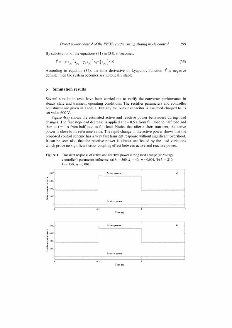
Figure 4(a) shows the estimated active and reactive power behaviours during load changes. The first step-load decrease is applied at t = 0.5 s from full load to half load and then at t = 1 s from half load to full load. Notice that after a short transient, the active power is close to its reference value. The rapid change in the active power shows that the proposed control scheme has a very fast transient response without significant overshoot. It can be seen also that the reactive power is almost unaffected by the load variations which prove no significant cross-coupling effect between active and reactive power.
Figure 4 Transient response of active and reactive power during load change [dc voltage controller’s parameters influence: (a) k1 = 360, k2 = 40, 0.001,η = (b) k1 = 210, k2 = 350, 0.001]η =
0 0.5 1 1.5
0
2000
4000
6000
8000
Time (s)
Ista
ntan
eous
pow
ers
Active power
Reative power
a)
0 0.5 1 1.5
0
2000
4000
6000
8000
Time (s)
Ista
ntan
eous
pow
ers
Active power
Reative power
b)

300 S. Barkat et al.
Table 1 Electrical parameters of power circuit and control coefficients
Nominal power 3.6 kW Line RMS phase voltage 220 V Line frequency 50 Hz Line resistance 250 mΩ Line inductor 10 mH Output filter capacitor 5 mF Nominal output dc voltage 600 V Switching frequency 10 kHz Power controller constants kip = 9,000, kiq = 145,000, γ1 = 5,000, γ2 = 100 dc voltage controller constants k1 = 360, k2 = 40, η = 0.001
Figure 5 shows the transient response of dc output voltage during a load variation. During this critical load change, the dc output voltage remains almost constant, with minimum overshoot and undershoot. A fast rejection of the disturbance is possible, thanks to a good choice of the dc voltage controller parameters. However, this has a clear repercussion on the active power response, as shown in Figure 4(b).
Figure 5 Output dc voltage during load change [dc voltage controller’s parameters influence: (a) k1 = 360, k2 = 40, 0.001,η = (b) k1 = 210, k2 = 350, 0.001]η =
0 0.5 1 1.5598
598.5
599
599.5
600
600.5
601
601.5
602
Time (s)
Out
put v
olta
ge (V
)
a)b)
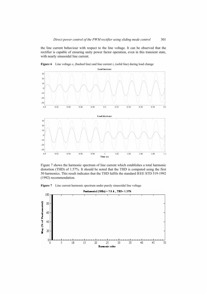
Figure 6 depicts the transient response of line current of the first phase to a load step change. In the same plot, the corresponding line voltage is included. It is important to note that the line voltage is scaled down by a factor of twenty in order to easily compare
Direct power control of the PWM rectifier using sliding mode control 301
the line current behaviour with respect to the line voltage. It can be observed that the rectifier is capable of ensuring unity power factor operation, even in this transient state, with nearly sinusoidal line current.
Figure 6 Line voltage e1 (bashed line) and line current i1 (solid line) during load change
0.4 0.42 0.44 0.46 0.48 0.5 0.52 0.54 0.56 0.58 0.6
-30
-20
-10
0
10
20
30
Load increase
0.9 0.92 0.94 0.96 0.98 1 1.02 1.04 1.06 1.08 1.1
-30
-20
-10
0
10
20
30
Time (s)
Load decrease
Figure 7 shows the harmonic spectrum of line current which establishes a total harmonic distortion (THD) of 1.57%. It should be noted that the THD is computed using the first 50 harmonics. This result indicates that the THD fulfils the standard IEEE STD 519-1992 (1992) recommendation.
Figure 7 Line current harmonic spectrum under purely sinusoidal line voltage

302 S. Barkat et al.
Figure 8 describes the waveforms of line voltage and line current with distorted line voltage. It can be seen that with a weak distortion factor (5% of fifth harmonic) the performances are not completely degraded and the rectifier still ensures a power-factor close to the unit. As shown in Figure 9, the distortion increase the line current THD and leads to the appearance of new harmonics whose amplitudes are proportional to the distortion rate.
Figure 8 Line voltage e1 (bashed line) and line current i1 (solid line) with distorted line voltage (5% of fifth harmonic) in steady state operation
0.4 0.41 0.42 0.43 0.44 0.45 0.46 0.47 0.48
-30
-20
-10
0
10
20
30
Time (s)
Figure 9 Line current harmonic spectrum under distorted line voltage
Direct power control of the PWM rectifier using sliding mode control 303
6 Comparative analysis of the results
An interesting comparison between various control techniques of the PWM rectifier has been made by Malinowski et al. (2003). The study is focused on virtual flux-oriented control, virtual-based DPC, voltage-oriented control and voltage-based DPC.
In the same spirit, the proposed control scheme is compared to the conventional one from the point of view of the dynamic performance. Furthermore, the effects of non-ideal line voltage and poor line inductance estimation on the current drawn by a rectifier have been examined.
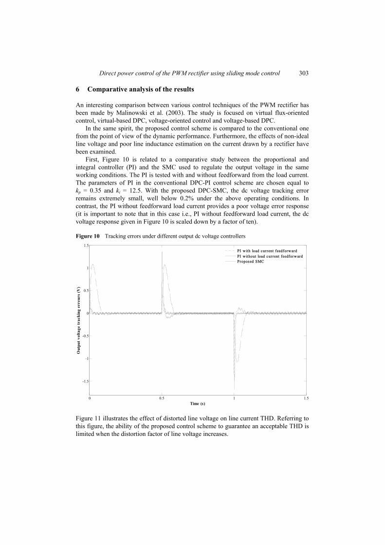
First, Figure 10 is related to a comparative study between the proportional and integral controller (PI) and the SMC used to regulate the output voltage in the same working conditions. The PI is tested with and without feedforward from the load current. The parameters of PI in the conventional DPC-PI control scheme are chosen equal to kp = 0.35 and ki = 12.5. With the proposed DPC-SMC, the dc voltage tracking error remains extremely small, well below 0.2% under the above operating conditions. In contrast, the PI without feedforward load current provides a poor voltage error response (it is important to note that in this case i.e., PI without feedforward load current, the dc voltage response given in Figure 10 is scaled down by a factor of ten).
Figure 10 Tracking errors under different output dc voltage controllers
0 0.5 1 1.5
-1.5
-1
-0.5
0
0.5
1
1.5
Time (s)
Out
put v
olta
ge tr
acki
ng e
rreu
rs (V
)
PI w ith load c urrent feedforw ardPI w ithout load c urrent feedforw ardProposed SMC
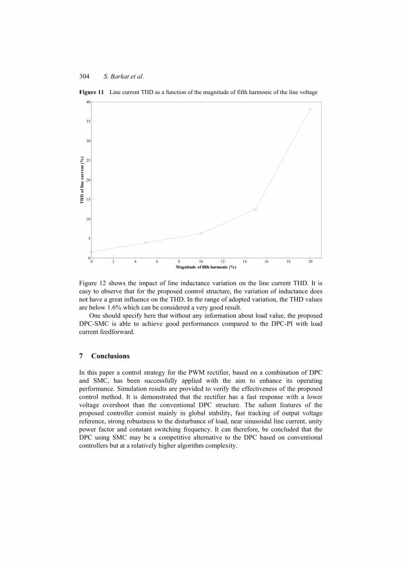
Figure 11 illustrates the effect of distorted line voltage on line current THD. Referring to this figure, the ability of the proposed control scheme to guarantee an acceptable THD is limited when the distortion factor of line voltage increases.
304 S. Barkat et al.
Figure 11 Line current THD as a function of the magnitude of fifth harmonic of the line voltage
0 2 4 6 8 10 12 14 16 18 200
5
10
15
20
25
30
35
40
Magnitude of fifth harmonic (%)
TH
D o
f lin
e cu
rren
t (%
)
Figure 12 shows the impact of line inductance variation on the line current THD. It is easy to observe that for the proposed control structure, the variation of inductance does not have a great influence on the THD. In the range of adopted variation, the THD values are below 1.6% which can be considered a very good result.
One should specify here that without any information about load value, the proposed DPC-SMC is able to achieve good performances compared to the DPC-PI with load current feedforward.
7 Conclusions
In this paper a control strategy for the PWM rectifier, based on a combination of DPC and SMC, has been successfully applied with the aim to enhance its operating performance. Simulation results are provided to verify the effectiveness of the proposed control method. It is demonstrated that the rectifier has a fast response with a lower voltage overshoot than the conventional DPC structure. The salient features of the proposed controller consist mainly in global stability, fast tracking of output voltage reference, strong robustness to the disturbance of load, near sinusoidal line current, unity power factor and constant switching frequency. It can therefore, be concluded that the DPC using SMC may be a competitive alternative to the DPC based on conventional controllers but at a relatively higher algorithm complexity.

Direct power control of the PWM rectifier using sliding mode control 305
Figure 12 Line current THD as a function of the line inductance variation
-30 -20 -10 0 10 20 30
1.48
1.5
1.52
1.54
1.56
1.58
Line inductance variation (%)
TH
D o
f lin
e cu
rren
t (%
)
References Cecati, C., Dell’Aquilla, A., Lecci, A. and Liserre, M. (2005) ‘Implementation issues of a
fuzzy-logic based three-phase active rectifier employing only voltage sensors’, IEEE Trans. Ind. Electron., Vol. 52, No. 2, pp.378–385.
Cecati, C., Dell’Aquilla, A., Liserre, M. and Ometto, A. (2003) ‘A fuzzy-logic based controller for active rectifier’, IEEE Trans. Ind. Applicat., Vol. 39, No. 1, pp.105–112.
IEC 61000-3-4 (1998) ‘Electromagnetic compatibility (EMC), part 3–2, limits: limitations of emissions of harmonic currents in low-voltage power supply systems for equipment with rated current greater than 16A’.
IEEE STD 519-1992 (1992) ‘Recommended practices and requirements for harmonic control in electrical power systems’.
Jasinski, M., Liserre, M., Blaaberg, F. and Cishowlas, M. (2002) ‘Fuzzy logic current controller for PWM rectifiers’, in Proc. of IECON, pp.1300–1305.
Jung, J., Lim, S. and Nam, K. (1999) ‘A feedback linearizing control scheme for PWM converter-inverter having a very small dc-link capacitor’, IEEE Trans. Ind. Applicat., Vol. 35, No. 5, pp.1124–1131.
Kazmierkowski, M.P. and Malesani, L. (1998) ‘Current control techniques for three-phase voltage-source PWM converters: a survey’, IEEE Trans. Ind. Electron, Vol. 45, No. 5, pp.691–703.
Komurcugil, H. and Kukrer, O. (1998) ‘Lyapunov-based control for three-phase PWM AC/DC voltage-source converters’, IEEE Trans. Power Electron., Vol. 13, No. 5, pp.801–813.
Kwon, B.H., Youm, J.H. and Lim, J.W. (1999) ‘A line-voltage sensorless synchronous rectifier’, IEEE Trans. Power Electron, Vol. 14, No. 5, pp.966–972.

306 S. Barkat et al.
Lee, D.C., Lee, G.M. and Lee, K.D. (2000) ‘DC-bus voltage control of three-phase AC/DC PWM converters using feedback linearization’, IEEE Trans. Ind. Applicat., Vol. 36, No. 3, pp.826–833.
Malinowski, M., Jasinski, M. and Kazmierkowski, M.P. (2004) ‘Simple direct power control of three-phase PWM rectifier using space-vector modulation (DPC-SVM)’, IEEE Transactions on Industrial Electronics, Vol. 51, No. 2, pp.447–454.
Malinowski, M., Kazmierkowski, M.P. and Trzynadlowski, A.M. (2003) ‘A comparative study of control techniques for PWM rectifiers in AC adjustable speed drives’, IEEE Transactions on Power Electronics, Vol. 18, No. 6, pp.1390–1396.
Malinowski, M., Kazmierkowski, M.P., Hansen, S., Blaabjerg, F. and Marques, G.D. (2001) ‘Virtual flux based direct power control of three-phase PWM rectifiers’, IEEE Trans. Ind. Appl., Vol. 37, No. 4, pp.1019–1027.
Manninen, V. (1995) ‘Application of direct torque control modulation technology to a line converter’, in Proceeding of the European Conference on Power Electronics and Applications EPE’95, Servilla, Spain, pp.1292–1296.
Noguchi, T., Tomiki, H., Kondo, S. and Takahashi, I. (1998) ‘Direct power control of PWM converter without power-source voltage sensors’, IEEE Trans. Ind. Applicat., Vol. 34, No. 3, pp.473–479.
Perez, M., Ortega, R. and Espinoza, J.R. (2004) ‘Passivity-based PI control of switching power converters’, IEEE Trans Contr. Syst. Techn., Vol. 12, No. 6, pp.881–890.
Ryvkin, S., Schmidt-Obermoeller, R. and Steimel, A. (2008) ‘Sliding-mode based control for a three-level inverter drive’, IEEE Transactions on Industrial Electronics, Vol. 55, No. 11, pp.3828–3835.
Shtessel, Y., Baev, S. and Biglari, H. (2008) ‘Unity power factor control in three-phase AC/DC boost converter using sliding modes’, IEEE Transactions on Industrial Electronics, Vol. 55, No. 11, pp.3874–3882.
Slotine, J.J.E., and Li, W. (1991) Applied Nonlinear Control, Prentice Hall, Englewood Cliffs. Subjak, J.S. and Mcquilkin, J.S (1990) ‘Harmonic-causes, effects, measurements, analysis:
an update’, IEEE Transactions on Industry Applications, Vol. 26, No. 6, pp.1034–1042. Utkin, V., Gulder, J. and Shi, J. (1999) Sliding Mode Control in Electromechanical Systems, Taylor
and Francis, New York.
Copyright © 2022 FDOKUMEN