Galaxy Power System 4848/100 with Dual Rectifier Shelf ...
112
User’s Guide Select Code 167-792-166 Comcode 108994042 Issue 3 February 2008 Galaxy Power System 4848/100 with Dual Rectifier Shelf (GPS 4848/100) H569-434 Note: Instructions in this manual reference installation and setup of the Galaxy Millennium Controller. For Galaxy Millennium II installation and setup, refer to the Millennium II Product Manual 167-792-181.
-
Upload
khangminh22 -
Category
Documents
-
view
3 -
download
0
Transcript of Galaxy Power System 4848/100 with Dual Rectifier Shelf ...

User’s Guide Select Code 167-792-166 Comcode 108994042 Issue 3February 2008
Galaxy Power System 4848/100 with Dual Rectifier Shelf
(GPS 4848/100) H569-434
Note: Instructions in this manual reference installation and setup of the Galaxy Millennium Controller. For Galaxy Millennium II installation and setup, refer to the Millennium II Product Manual 167-792-181.


User’s Guide Select Code 167-792-166 Comcode 108994042 Issue 3February 2008
Galaxy Power System 4848/100 with Dual Rectifier Shelf
(GPS 4848/100) H569-434
© 2008 Lineage Power All International Rights Reserved Printed in U.S.A.
Notice:The information, specifications, and procedures in this manual are subject to change without notice. Lineage Power assumes no responsibility for any errors that may appear in this document.


Galaxy Power System 4848/100 with Dual Rectifier Shelf
Table of Contents
1 IntroductionGPS 4848/100 1-1
Overview 1-1Illustration 1-2Safety 1-3Electromagnetic Compliance 1-3CE Marking 1-3Telcordia 1-3
Customer Service Contacts 1-4Customer Service, Technical Support, Product
Repair and Return, and Warranty Service 1-4Customer Training 1-4Downloads and Software 1-4
2 System DescriptionOverview 2-1
Block Diagram 2-1System Components 2-2
Architecture 2-3Introduction 2-3Distributed 2-3Centralized 2-5Standard 2-7Non-Traditional 2-7
3 Galaxy Millennium ControllerOverview 3-1
Mounting Location 3-1Circuit Boards 3-1
Reference Material 3-1Controller Product Manual 3-1RPM System Product Manual 3-1
User Interface and Display 3-2Front Panel 3-2Default Display 3-2LEDs 3-3Pushbutton Controls 3-3Test Jacks 3-4
Issue 3 February 2008 Table of Contents - 1

Galaxy Power System 4848/100 with Dual Rectifier Shelf
4 Rectifiers595 Series 4-1
Overview 4-1Front Panel Display 4-2
Power Switch 4-2Status Indicators 4-2Current Display 4-2Lamp Test 4-2Illustration 4-2
Features 4-3Output Voltage Adjustment 4-3Output Current “Walk-in” 4-3Electronic Current Limit 4-3Selective High Voltage Shutdown (SHVSD) 4-3Backup High Voltage Shutdown (BHVSD) 4-3Restart 4-3Output Circuit Breaker 4-3Fan Alarm and Control 4-3Thermal Alarm 4-4Controller Communications Alarm 4-4Autonomous Operation of the Rectifier 4-4Connectorized 4-4“Forced” Load Sharing 4-4
5 AC Input PanelsOverview 5-1
AC Service 5-1Illustrations 5-1
6 Battery Connection PanelsOverview 6-1
Introduction 6-1Distributed Architecture 6-1Centralized Architecture 6-1Illustrations 6-1
7 DC Distribution PanelsOverview 7-1
Function 7-1Illustrations 7-1
2 - Table of Contents Issue 3 February 2008

Galaxy Power System 4848/100 with Dual Rectifier Shelf
8 Circuit BoardsOverview 8-1
Function 8-1Terminal Boards 8-1Alarm Boards 8-1Alarm/Terminal Boards 8-1BLJ Terminal Board 8-1Bay Interface Card 8-2Contactor Control Board 8-2
9 SpecificationsGPS 4848/100 9-1Rectifiers 9-4AC Input Panels 9-6Battery Connection Panels 9-7DC Distribution Panels 9-8
10 Safety
11 Maintenance and ReplacementRequirements 11-1
System 11-1Batteries 11-1Controller 11-1Rectifier 11-2Vacant Rectifier Positions 11-2Rectifier Fan Assembly 11-2
Replacement Procedures 11-3Installing or Replacing a Rectifier 11-3Removing a Rectifier 11-6Replacing the Rectifier Fan Assemblies 11-7
Testing 11-9Testing Additional Alarms After Replacing Rectifiers 11-9Testing Rectifiers and Load Share in Bay Expansions 11-9
Replacement Parts 11-10System 11-10Millennium Controller Circuit Boards 11-11
Additional Ordering Information 11-11Documentation 11-11Software 11-11
Issue 3 February 2008 Table of Contents - 3

Galaxy Power System 4848/100 with Dual Rectifier Shelf
12 Troubleshooting PreparationsPreliminary 12-1
Introduction 12-1Safety 12-1Tools 12-1
Troubleshooting Procedure 12-2Purpose 12-2Cabinet Alarm 12-2System Status 12-3Alarms Menu 12-3Troubleshooting Tables 12-3Identifying Problems 12-3
Reference Figures 12-4Figure Numbers and Titles 12-4Millennium Controller 12-4Rectifier 12-6Low Voltage Battery Disconnect 12-7AC Input 12-8AC Input 12-9DC Distribution 12-10Low Voltage Load Disconnect 12-11
13 Troubleshooting Millennium SystemsIntroduction 13-1
In This Section 13-1Preparation 13-1Technical Assistance 13-1
Troubleshooting Tables 13-2Organization 13-2Table Reference 13-2Rectifier Display Messages and LEDs 13-2Millennium Controller Display 13-3AC Alarm LED 13-3BATT Alarm LED 13-4CTRL Alarm LED 13-5DIST Alarm LED 13-9RECT Alarm LED 13-10BD and RM Alarm LEDs, or No LED 13-15
14 Product Warranty
Revision History
4 - Table of Contents Issue 3 February 2008
Galaxy Power System 4848/100 with Dual Rectifier Shelf
List of Figures
Figure 1-1: GPS 4848/100 With Millennium Controller 1-2
Figure 2-1: Block Diagram of the GPS 4848/100 (Distributed Architecture) 2-1
Figure 2-2: Distributed Architecture 2-4
Figure 2-3: Distributed Architecture Initial and Growth Cabinets 2-4
Figure 2-4: Centralized Architecture 2-5
Figure 2-5: Centralized Architecture Initial and Growth Cabinets 2-6
Figure 2-6: Non-Traditional Cabling Arrangements 2-7
Figure 3-1: Galaxy Millennium Controller Front Panel 3-2
Figure 4-1: Rectifier Front Panel 4-2
Figure 5-1: H569-434 G20/320/420 (ED83142-30 G3) 208/240V AC Input Circuit Breaker Panel - 4 Rectifier 5-2
Figure 5-2: H569-434 G21/23/321/323/421 (ED83142-30 G4) 208/240/480V AC Input Circuit Breaker Panel - 6 Rectifier 5-2
Figure 5-3: H569-434 G334/335 (ED83142-30 G24/25) 208/240/480V AC Input Circuit Breaker Panel - 12 Rectifier 5-3
Figure 5-4: H569-434 G22/322 (ED83142-30 G2) 480V AC Input Circuit Breaker Panel - 4 Rectifier 5-3
Figure 5-5: H569-434 G24/25/26/27/324/325/326/ 327/330/331 (ED83142-30 G5)208/240/480V AC Input Terminal Strip Panel - 6 Rectifier 5-4
Figure 5-6: H569-434 G128/129/130/131 (ED83142-30 G18) 208/240/480V AC Input Terminal Strip Panel - 8 Rectifier 5-4
Issue 3 February 2008 List of Figures - 1

Galaxy Power System 4848/100 with Dual Rectifier Shelf
Figure 5-7: H569-434 G328/329/332/333 (ED83142-30 G26) 208/240/480V AC Input Terminal Strip Panel - 14 Rectifier 5-5
Figure 5-8: H569-434 G70/370/470 (ED83142-30 G10) 480V 65kAIC AC Input Circuit Breaker Panel - 4 Rectifier 5-5
Figure 5-9: H569-434 G71/371/471 (ED83142-30 G11) 480V 65kAIC AC Input Circuit Breaker Panel - 6 Rectifier 5-6
Figure 6-1: H569-434 G30 (ED83143-31 G32) Battery Connection Panel 6-2
Figure 6-2: H569-434 G31 (ED83143-31 G31) Battery Connection Panel 6-2
Figure 6-3: H569-434 G32/32A (ED83143-31 G30/30A) Battery Connection Panel 6-3
Figure 6-4: H569-434 G34 (ED83143-31 G41) Battery Connection Panel 6-3
Figure 6-5: H569-434 G35 (ED83143-31 G42) Battery Connection Panel 6-4
Figure 6-6: H569-434 G37/38 (ED83143-31 G60/61) Battery (OLE) Connection Panel 6-4
Figure 6-7: H569-434 G80/81/82 (ED83143-31 G31/43) Battery Connection Panel 6-5
Figure 6-8: H569-434 G86/87 (ED83143-31 G63/64) Battery Connection Panel 6-6
Figure 6-9: H569-434 G39 (ED83143-31 G36) Battery Connection Panel 6-6
Figure 7-1: H569-434 G40/45/50/55 (ED83143-31 G11) 400A DC Distribution Panel 7-2
Figure 7-2: H569-434 G41/46/51/56 (ED83143-31 G12) 400A DC Distribution Panel 7-2
Figure 7-3: H569-434 G42/47 (ED83143-31 G2) 600A DC Distribution Panel 7-3
Figure 7-4: H569-434 G43 (ED83143-31 G1) 1200A DC Distribution Panel 7-3
2 - List of Figures Issue 3 February 2008

Galaxy Power System 4848/100 with Dual Rectifier Shelf
Figure 7-5: H569-434 G48 (ED83143-31 G5) 1000A DC Distribution Panel 7-4
Figure 7-6: H569-434 G52 (ED83143-31 G53) 600A DC Distribution Panel 7-4
Figure 7-7: H569-434 G53/57 (ED83143-31 G55) 1000A DC Distribution Panel 7-5
Figure 7-8: H569-434 G60/61/65/66 (ED83143-31 G71) 600A DC Distribution Panel 7-5
Figure 7-9: H569-434 G67 (ED83143-31 G22) 600A DC Distribution Panel 7-6
Figure 7-10: H569-434 G68 (ED83143-31 G21) 1200A DC Distribution Panel 7-6
Figure 7-11: H569-434 G96 (ED83143-31 G15) 510A DC Distribution Panel 7-7
Figure 7-12: H569-434 G97 (ED83143-31 G16) 14-Position, and H569-434 G98 (ED83143-31 G17) 22-Position DC Distribution Panel 7-7
Figure 7-13: H569-434 G54 (ED83143-31 G54) 5- Position DC Distribution Panel 7-8
Figure 7-14: H569-434 G58 (ED83143-31 G58) 6- Position GMT DC Distribution Panel 7-8
Figure 7-15: H569-434 G59 (ED83143-31 G56) 2- Position Fuse Distribution Panel 7-9
Figure 11-1: Installing a Rectifier in a Rectifier Shelf 11-4
Figure 11-2: Rectifier Faceplate Assembly 11-7
Figure 11-3: Rectifier Fan Assembly 11-8
Figure 12-1: Location of Cabinet Alarm Light and Controller 12-2
Figure 12-2: Millennium Controller Display 12-5
Figure 12-3: Millennium Controller Fuses and Circuit Boards 12-5
Figure 12-4: Rectifier Display 12-6
Issue 3 February 2008 List of Figures - 3

Galaxy Power System 4848/100 with Dual Rectifier Shelf
Figure 12-5: Low Voltage Battery Disconnect Contactor Control Switches 12-7
Figure 12-6: AC Input Panel and Rectifier Positions, 6 Rectifiers 12-8
Figure 12-7: AC Input Panel and Rectifier Positions, 12 Rectifiers 12-9
Figure 12-8: DC Distribution Panel 12-10
Figure 12-9: Low Voltage Load Disconnect Contactor Control Switches 12-11
4 - List of Figures Issue 3 February 2008

Galaxy Power System 4848/100 with Dual Rectifier Shelf
Issue 3 February 2008 List of Tables - 1
List of Tables
Table 9-A: Galaxy Power System 4848/100 Specifications 9-1
Table 9-B: 595LT Series Rectifier Specifications 9-4
Table 9-C: Rectifier Display Messages and LEDs 9-5
Table 9-D: AC Panels 9-6
Table 9-E: Battery Connection Panels 9-7
Table 9-F: DC Distribution Panels 9-8
Table 11-A: GPS 4848/100 Replacement Parts 11-10
Table 11-B: Galaxy Millennium Controller Circuit Boards 11-11
Table 11-C: Product Documentation 11-11
Table 13-A: AC Alarms 13-3
Table 13-B: Battery Alarms 13-4
Table 13-C: Controller Alarms 13-5
Table 13-D: Distribution Alarms 13-9
Table 13-E: Rectifier Related Alarms 13-10
Table 13-F: Miscellaneous Alarms 13-15


Galaxy Power System 4848/100 with Dual Rectifier Shelf
1 Introduction
GPS 4848/100
Overview The Galaxy Power System (GPS) 4848/100 provides -48 volt telecommunications powering solutions in worldwide markets. The GPS 4848/100 combines 220 and 200-ampere, fan-cooled, switchmode rectifiers, microprocessor control technologies, battery and load disconnect/reconnect options, and a comprehensive line of fuse and circuit breaker dc distribution options in a modular front-access design. This modularity ensures easy access, simplified installation and maintenance, and allows the system to expand in capacity and features as power needs grow.
With 14,080-ampere maximum capacity, distribution flexibility, and universal ac input capability, the GPS 4848/100 supports switching, transmission, and wireless applications in central office locations and environmentally controlled remote sites (huts or vaults). For centralized architecture, bus bars are available to 14,080A.
Notes This document includes information for 595LT series rectifiers. For information about 595A and 595B series rectifiers see the GPS 4848/100 product Manual.
595A and 595B series rectifiers (full width, one per shelf) are fully supported by GPS 4848/100 with Dual Rectifier Shelves.
Issue 3 February 2008 Introduction 1 - 1

Galaxy Power System 4848/100 with Dual Rectifier Shelf
GPS 4848/100, continued
Illustration Figure 1-1 is an isometric view of the GPS 4848/100 with a Millennium Controller.
Figure 1-1: GPS 4848/100 With Millennium Controller
GalaxyMillenniumController
BLJ3TerminalBoard
Battery Connection Panel
AC Panel
595LT Series220A Rectifiers
DC Distribution
1 - 2 Introduction Issue 3 February 2008

Galaxy Power System 4848/100 with Dual Rectifier Shelf
GPS 4848/100, continued
Safety • UL1 Listed (US and Canada): UL Subject 1801 with applicable sections of UL1950/CSA2 950)
• VDE Licensed to VDE 0805/IEC950/EN60950
Electromagnetic Compliance
• Emission:
– FCC Part 15 Class B
– EN55022 (CISPR 22) Radiated/Conducted Emission, Class B
• Immunity
– IEC/EN 61000-4-2 ESD level 3 and 4
– IEC/EN 61000-4-3 Radiated Immunity, 10V/m
– IEC/EN 61000-4-4 Electrical Fast transients/Burst, level 4
– IEC/EN 61000-4-5 Lightning Surge, level 4
CE Marking • CE marked per European Union Council Directives:
– Low-Voltage Directive (73/23/EEC) and
– EMC Directive (89/336/EEC) as amended by CE Marking Directive (93/68/EEC)
Telcordia • GR-63 and GR-1089 NEBS (including Level 3 testing)
• Report by an independent test laboratory - NRTL
1.UL is a registered trademark of Underwriters Laboratories, Inc.2.CSA is a registered trademark of Canadian Standards Association.
Issue 3 February 2008 Introduction 1 - 3

Galaxy Power System 4848/100 with Dual Rectifier Shelf
Customer Service Contacts
Customer Service, Technical Support, Product Repair and Return, and Warranty Service
For customers in the United States, Canada, Puerto Rico, and the US Virgin Islands, call 1-800-THE-1PWR (1-800-843-1797). This number is staffed from 7:00 am to 5:00 pm Central Time (zone 6), Monday through Friday, on normal business days. At other times this number is still available, but for emergencies only. Services provided through this contact include initiating the spare parts procurement process, ordering documents, product warranty administration, and providing other product and service information.
For other customers worldwide the 800 number may be accessed after first dialing the AT&T Direct country code for the country where the call is originating, or you may contact your local field support center or your sales representative to discuss your specific needs.
Customer Training Lineage Power offers customer training on many Power Systems products. For information call 1-972-284-2163. This number is answered from 8:00 a.m. until 4:30 p.m., Central Time Zone (Zone 6), Monday through Friday.
Downloads and Software
To download the latest product information, product software and software upgrades, visit our web site at http://www.lineagepower.com
1 - 4 Introduction Issue 3 February 2008

Galaxy Power System 4848/100 with Dual Rectifier Shelf
2 System Description
Overview
Block Diagram Figure 2-1 shows a basic block diagram of the Galaxy Power System 4848/100. It illustrates the arrangement and interconnections of the system components from the ac input to the dc output.
Figure 2-1: Block Diagram of the GPS 4848/100(Distributed Architecture)
LVLD
DISCHG RTN
LVLDControlBoard
Rectifiers
DC Distribution
Controller
ReturnBus(+)
To 48 VoltLoads
AC InputPower
48VReturns
LVBD
BAT BUS
CHG RTN
LVBDControlBoard
Battery Distribution
Battery (-)
BatteryShunt
Battery (+)
COGND
Sense/ControlConnections
AC Input
ChgBus(-)
Issue 3 February 2008 System Description 2 - 1

Galaxy Power System 4848/100 with Dual Rectifier Shelf
Overview, continued
System Components
The power system accepts alternating current from the commercial utility or a standby ac power source and rectifies it to produce dc power for the using equipment. The system’s control and alarm functions interact with the rectifiers and the office. In addition, the system provides overcurrent protection and charge, discharge, and distribution facilities. Battery reserve automatically provides a source of dc power if the commercial or standby ac fails. Battery reserve can be engineered to supply dc power for a specific period of time. In normal practice, battery capacity is sized to provide 3 to 8 hours of reserve time.
AC Input connects the commercial and/or standby ac power sources to the rectifiers within the system and provides overcurrent protection. In some applications the ac service is wired directly to the rectifiers and overcurrent protection is provided at the service panel.
Rectifiers convert an ac source voltage into the dc voltage level required to charge and float the batteries and to power the using equipment.
Controller provides the local and remote control, monitoring, and diagnostic functions required to administer the power system.
Batteries provide energy storage for an uninterrupted power feed to the using equipment during loss of ac input or rectifier failure.
DC Distribution Panel provides overcurrent protection, connection points for the using equipment, and bus bars used to interconnect the rectifiers, batteries, and dc distribution.
Battery Connection Panel provides connection points for the battery strings through battery disconnect fuse, contactors, current monitoring shunts, and equalize converters.
2 - 2 System Description Issue 3 February 2008

Galaxy Power System 4848/100 with Dual Rectifier Shelf
Architecture
Introduction For the GPS 4848/100 system, the basic system components, i.e., ac input panels, battery connection panels, dc distribution panels, rectifiers, and controller, can be configured to form two distinct system architectures: distributed or centralized.
Distributed In this system each cabinet contains ac distribution, dc distribution panels, battery connection panels, rectifiers, termination points for load circuits, and a battery shunt. The initial cabinet also contains the system controller and, as such, it can function as a stand-alone system. The rectifier output buses are interconnected to permit cabinets to share current and ensure common voltage references for all system rectifiers. Because each cabinet is basically a self-contained system, the overall system capacity can be increased by simply adding cabinet/battery entities. However, growing the system requires a distinct, dedicated floor plan.
During normal operation, the readings from the battery shunts are summed and subtracted from the rectifier current to obtain the system load current. While the batteries are providing the system load power, the individual battery shunts may be monitored to determine the status of the individual battery sections.
Cabinets can be equipped with load and/or battery disconnect/reconnect contactors. Battery contactors prevent battery damage during deep discharges by disconnecting batteries. Load contactors can extend the time critical loads operate on battery discharge by disconnecting non-critical loads during discharge.
Figure 2-2 shows an example of GPS 4848/100 components configured in a distributed architecture; Figure 2-3 gives a front view of the distributed initial and growth cabinets.
Issue 3 February 2008 System Description 2 - 3

Galaxy Power System 4848/100 with Dual Rectifier Shelf
Figure 2-2: Distributed Architecture
Controland
Monitor
Battery Shunt
To Loads
Battery String
Architecture, continued
Figure 2-3: Distributed Architecture Initial and Growth Cabinets
Initial Cabinet Growth Cabinet
2 - 4 System Description Issue 3 February 2008
Galaxy Power System 4848/100 with Dual Rectifier Shelf
Architecture, continued
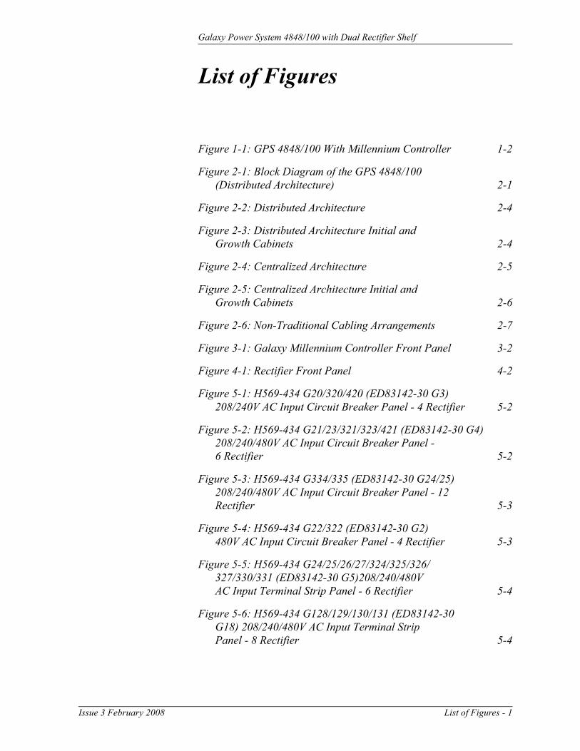
Centralized Figure 2-4 shows GPS 4848/100 components configured in a centralized architecture; Figure 2-5 provides a view of the centralized architecture initial and growth cabinets. Rectifiers, dc distribution panels, and batteries are cabled to external busbars where a single system shunt is provided to measure total system load current. The initial cabinet contains ac distribution, rectifiers, the controller, and termination points for the system interconnect cables. Growth cabinets contain ac distribution, rectifiers, and cable termination points. A separate cabinet provides load distribution and protection facilities and may include load disconnect/reconnect contactors.
This architecture requires extensive up-front planning to determine the ultimate system capacity and engineering to size the external busbars appropriately; however, the system plan is not constrained to dedicated layouts as required for distributed architecture systems.
Figure 2-4: Centralized Architecture
Charge Bus Charge Return Bus Discharge Return Bus
Battery Strings
PlantShunt
Controland
Monitor
Loads
Issue 3 February 2008 System Description 2 - 5

Galaxy Power System 4848/100 with Dual Rectifier Shelf
Architecture, continued
Figure 2-5: Centralized Architecture Initial and Growth Cabinets
Growth CabinetInitial Cabinet
2 - 6 System Description Issue 3 February 2008

Galaxy Power System 4848/100 with Dual Rectifier Shelf
Cabinet Cabling Options
Standard Standard cabinets are designed so that ac, battery, and dc load cables are run through the top of the cabinet.
Non-Traditional Any of the battery panels and dc load panels (shown in Sections 6 and 7) may be used in cabinets that have non-traditional cabling orientations. However, only G20, G22, G24, G26, and G27 ac panels (shown in Section 5) are available for these cabinets (see Figure 2-6). Suffixes of the ac panels indicate the cabling arrangements listed below:
AC Panel Suffix
Cabling Arrangement
AC Battery and DC Load
A Through bottom of cabinet Through bottom of cabinetB Through bottom of cabinet Through top of cabinetC Through top of cabinet Through bottom of cabinet
Note: Check H569-434 for availability.
Figure 2-6: Non-Traditional Cabling Arrangements
AC Input
Battery andDC Load Leads
AC Input
Battery andDC Load Leads
AC Input Battery andDC Load Leads
"A" Arrangement "B" Arrangement "C" Arrangement
REMOVEBEFOREADDINGSECOND
RECTIFIER
REMOVEBEFOREADDINGSECOND
RECTIFIER
REMOVEBEFOREADDINGSECOND
RECTIFIER
REMOVEBEFOREADDINGSECOND
RECTIFIER
REMOVEBEFOREADDINGSECOND
RECTIFIER
REMOVEBEFOREADDINGSECOND
RECTIFIER
REMOVEBEFOREADDINGSECOND
RECTIFIER
REMOVEBEFOREADDINGSECOND
RECTIFIER
REMOVEBEFOREADDINGSECOND
RECTIFIER
REMOVEBEFOREADDINGSECOND
RECTIFIER
REMOVEBEFOREADDINGSECOND
RECTIFIER
REMOVEBEFOREADDINGSECOND
RECTIFIER
Issue 3 February 2008 System Description 2 - 7


Galaxy Power System 4848/100 with Dual Rectifier Shelf
3 Galaxy Millennium Controller
Overview
Mounting Location The Galaxy Millennium Controller mounts inside the front door with the display viewed from the outside.
Circuit Boards The Galaxy Millennium Controller is equipped with a Basic control board for basic operations and an optional Intelligent control board that provides advanced local and remote monitoring and data acquisition features. These control boards monitor each other’s status and issue appropriate alarms in the event a failure occurs. Circuit packs are accessed by opening the hinged cover from the left side.
Reference Material
Controller Product Manual
A Galaxy Millennium Controller, Select Code 167-792-180, is furnished with every GPS 4848/100. Refer to the manual for information regarding configuration and operation.
RPM System Product Manual
Refer to the Galaxy Remote Peripheral Monitoring System product manual (Select Code 167-790-063) for additional information regarding module operation.
Issue 3 February 2008 Galaxy Millennium Controller 3 - 1

Galaxy Power System 4848/100 with Dual Rectifier Shelf
User Interface and Display
Front Panel The control panel displays alarm and status indicators and provides test jacks to monitor the system output. Keys are provided for interacting with various menus that configure and monitor the system. The controller menus can be viewed in either English or Spanish.
The user’s primary interface with the controller is a panel that includes a backlit LCD front panel display, two rows of LEDs, test jacks, and an array of simple pushbutton controls. See Figure 3-1.
Figure 3-1: Galaxy Millennium Controller Front Panel
Galaxy Millennium ControllerAlarm Status
Critical
Escape Help
EnterMenu
Equipment Status
AC System
Battery
Controller
Distribution
Rectifier
RemoteModules
Major
Minor
Normal
Battery onDischarge
V
Default Display The default display shows basic plant status. The controller returns to this display three minutes after the last time a key is pressed. The default screen display is similar to the following: The first line shows the number of alarms (0) and warnings (0) present in the system, the date and time. The next two lines show the plant voltage and the plant load. The last line shows the plant mode, which can be FLOAT, BOOST, STC (Slope Thermal Compensation), BTP (Battery Thermal Protection, a boost mode that offers protection against thermal runaway), or BATT TEST mode.
The information on the screen is updated automatically approximately every two seconds.
3 - 2 Galaxy Millennium Controller Issue 3 February 2008

Galaxy Power System 4848/100 with Dual Rectifier Shelf
User Interface and Display, continued
LEDs Two columns of LEDs show the severity and source of active alarms. An alarm event may activate two LEDs: one Alarm Status LED and one Equipment Status LED. More than one of the Equipment Status LEDs may be active simultaneously. In that case, the Alarm Status LED that is active will be that of the most severe active alarm.
The first column has five LEDs. The first four indicate the severity of the reported alarms: Critical, Major, Minor, and Normal. The fifth LED, labeled Battery on Discharge, illuminates when the plant voltage is below the threshold set for this alarm condition in the plant configuration.
The second column includes seven LEDs, six of which indicate the source of the alarm: AC System, Battery, Controller, Distribution, Rectifier, or Remote Module. The final Modem LED will be active whenever the controller modem port is in use.
The pushbutton identified with an illuminated lamp icon can be used to test the controller’s circuit pack and front panel LEDs. It will also test the indicators of all serially connected devices.
Pushbutton Controls
A group of pushbutton keys beneath the backlit LCD display provides the primary user interface with the controller. These keys are used singly or in combination to navigate through the controller’s menus. The following is the general description of these keys.
• Up arrow key: Use to navigate the menu; press the key to move the cursor up one line.
• Down arrow key: Use to navigate the menu; press the key to move the cursor down one line.
• Left arrow key: Use to navigate the menu; press the key to move the cursor left one field.
• Right arrow key: Use to navigate the menu; press the key to move the cursor right one field.
• MENU key: Press this key any time to view the MAIN menu.• HELP key: Press this key to display limited on-line help
information.• ENTER key: Use this key to select a menu item.• ESCAPE key: Use this key to return to the immediately higher
level menu.
Issue 3 February 2008 Galaxy Millennium Controller 3 - 3

Galaxy Power System 4848/100 with Dual Rectifier Shelf
User Interface and Display, continued
Test Jacks A pair of test jacks allows direct measurement of the system voltage being monitored, normally the battery voltage. This is the same point regulated as system voltage and displayed on the front panel.
3 - 4 Galaxy Millennium Controller Issue 3 February 2008

Galaxy Power System 4848/100 with Dual Rectifier Shelf
4 Rectifiers
595 Series
Overview Four rectifiers are available for the GPS 4848/100 system with dual rectifier shelves: 595A Series, 595B Series, 595LTA Series, and 595LTB Series.
GPS4848/100 Rectifiers
SeriesDC
CurrentRectifiers per Shelf
3-Phase AC Input Voltage
595A 200A 1 320-530Vac595B 200A 1 170-260Vac595LTA 220A 2 320-530Vac595LTB 220A 2 170-260Vac
The rectifiers are shipped separately from the cabinets for quick and straightforward installation into rectifier shelves at the site. Interconnections to ac input, dc output, and control signals occur automatically during insertion. The rectifiers are keyed to prevent installation of a rectifier with incompatible ac input. No operational settings or adjustments to potentiometers are necessary. The installer must set the rectifierís ID using the ON/STBY switch to allow the controller to to identify the rectifier for status and alarm reporting.
595A and 595B series rectifiers (full width, one per shelf) are fully supported. See GPS 4848/100 User's Guide for views and other details of 595A and 595B series rectifiers.
Issue 3 February 2008 Rectifiers 4 - 1

Galaxy Power System 4848/100 with Dual Rectifier Shelf
Front Panel Display
Power Switch This three-position switch has two functions:
• It controls the on/standby state of the rectifier.
• It is used to set the rectifier ID.
Status Indicators In addition to the ON and STBY LEDs, four other LEDs on the rectifier’s faceplate indicate the rectifier’s condition.
• The ALM LED is red and lights when a thermal alarm occurs or a rectifier fail condition occurs. This LED blinks when communication with the plant controller is not active.
• The LIM LED is yellow lights when the unit is in current limit.
• The FAN ALM LED is red and lights when the fan inside the rectifier is not functioning properly.
• The EQL LED is yellow and lights when the rectifier is in equalize mode.
Current Display This display indicates the current of the rectifier. Upon specific no-power conditions, the 3-digit display will show informative messages.
Lamp Test To test the LEDs on the rectifier front panel, use the Lamp Test feature of the controller.
Illustration
Figure 4-1: Rectifier Front Panel
ABC12345678Model: 595LTA
480V 48VRECTIFIERKZO41234567 SX:X
DC
220A/48V
ON
STBY ALM LIM FANALM
BST
4 - 2 Rectifiers Issue 3 February 2008

Galaxy Power System 4848/100 with Dual Rectifier Shelf
Features
Output Voltage Adjustment
This feature allows the rectifier output voltage to be set and regulated by the controller.
Output Current “Walk-in”
This feature controls the time (up to eight seconds) required for the rectifier to reach normal operating conditions after it is turned on. This feature minimizes the starting surge on the customer's power source.
Electronic Current Limit
When the output current tends to increase above the current limit set point (30% to 100% of maximum output), the current limit circuit overrides voltage regulation and load share to safely limit the output current of the rectifier, thus preventing damage to itself, the battery, or the load.
Selective High Voltage Shutdown (SHVSD)
This feature allows the rectifier to respond and shut down at the output high voltage threshold set through the Galaxy controller.
Backup High Voltage Shutdown (BHVSD)
This is a hardwired feature independent of the rectifier’s microcontroller. This feature is always active and will operate whether communicating with the controller or not and whether the rectifier's microcontroller is active or failed.
Restart Upon shutdown, the rectifier will attempt to restart. The rectifier will try to restart three times before issuing a rectifier fail alarm to the controller. The rectifier will also accept a restart command from the controller for a remote restart.
Output Circuit Breaker
The output circuit breaker located on the front panel protects the power system from rectifier malfunction and may be used to disconnect the rectifier from the system output bus.
Fan Alarm and Control
The rectifier contains two cooling fans whose speed is based on ambient temperature and output power level. The fan’s speed is lowered during low-load and low-temperature conditions to minimize audible noise and maximize fan life.
Issue 3 February 2008 Rectifiers 4 - 3

Galaxy Power System 4848/100 with Dual Rectifier Shelf
Features, continued
Thermal Alarm The rectifier senses the internal operating temperature and will issue a thermal alarm if the internal temperature exceeds a safe operating level. Ambient temperatures above the maximum rating may result in a rectifier shutdown and the issuing of a thermal alarm (TA).
Controller Communications Alarm
When communications between the rectifier and controller are interrupted, the rectifier continues to operate and the red ALM LED on the rectifier blinks.
Autonomous Operation of the Rectifier
If communication with the Galaxy controller is lost, the rectifier will continue to operate and deliver regulated power to the system load.
Connectorized The rectifiers provide the controller with a full complement of status and alarm messages. The rectifier status and alarm signals, ac input, and dc output are all connectorized for easy installation and maintenance. All connections automatically occur as the rectifier is physically mated to its shelf.
“Forced” Load Sharing
The controller forces rectifiers to load share by sending messages to them. In the event communication to the controller is lost or the controller malfunctions, load share balance is maintained while ac or dc power is continuously applied to the rectifiers.
4 - 4 Rectifiers Issue 3 February 2008

Galaxy Power System 4848/100 with Dual Rectifier Shelf
5 AC Input Panels
Overview
AC Service The ac input panel provides the facility to terminate the 3-phase ac service to the GPS 4848/100. Depending upon the option ordered, the panel will connect 3-wire delta or 3-wire wye service to provide the phase-to-phase ac voltage required for the rectifiers.
In some systems, circuit breakers are provided in the AC Input Panel to protect the conductors providing ac service to the individual rectifiers. In other systems, the circuit breakers protecting these conductors are located in the building’s ac service panel. In either case, conductors to each rectifier are protected by a dedicated circuit breaker.
Note: All wire sizes were based on the US National Electric Code.
Illustrations Circuit breaker panels are shown in Figures 5-1 through 5-4, 5-8, and 5-9. Terminal strip panels are shown in Figures 5-5 through 5-7.
Issue 3 February 2008 AC Input Panels 5 - 1

Galaxy Power System 4848/100 with Dual Rectifier Shelf
Figure 5-1: H569-434 G20/320/420 (ED83142-30 G3) 208/240V AC Input Circuit Breaker Panel - 4 Rectifier
Figure 5-2: H569-434 G21/23/321/323/421 (ED83142-30 G4) 208/240/480V AC Input Circuit Breaker Panel - 6 Rectifier
5 - 2 AC Input Panels Issue 3 February 2008

Galaxy Power System 4848/100 with Dual Rectifier Shelf
Figure 5-3: H569-434 G334/335 (ED83142-30 G24/25) 208/240/480V AC Input Circuit Breaker Panel - 12 Rectifier
Figure 5-4: H569-434 G22/322 (ED83142-30 G2) 480V AC Input Circuit Breaker Panel - 4 Rectifier
Issue 3 February 2008 AC Input Panels 5 - 3

Galaxy Power System 4848/100 with Dual Rectifier Shelf
Figure 5-5: H569-434 G24/25/26/27/324/325/326/327/330/331 (ED83142-30 G5) 208/240/480V AC Input Terminal Strip Panel - 6 Rectifier
Figure 5-6: H569-434 G128/129/130/131 (ED83142-30 G18) 208/240/480V AC Input Terminal Strip Panel - 8 Rectifier
5 - 4 AC Input Panels Issue 3 February 2008

Galaxy Power System 4848/100 with Dual Rectifier Shelf
Figure 5-7: H569-434 G328/329/332/333 (ED83142-30 G26) 208/240/480V AC Input Terminal Strip Panel - 14 Rectifier
SCREWTORQUE:
25 IN-LB
TO
VAC SERVICE
------------------
L1
L1
L1
L2
L2
L2
L3
L3
L3
L1
L1
L1
L1
L2
L2
L2
L2
L3
L3
L3
L3
INPUT 9INPUT 10
INPUT 11
INPUT 12
INPUT 1
INPUT 2
INPUT 3
INPUT 4
L1
L1
L2L3
L1
L1
L2
L2
L3
INPUT 13INPUT 5
INPUT 6
Figure 5-8: H569-434 G70/370/470 (ED83142-30 G10) 480V 65kAIC AC Input Circuit Breaker Panel - 4 Rectifier
Issue 3 February 2008 AC Input Panels 5 - 5

Galaxy Power System 4848/100 with Dual Rectifier Shelf
Figure 5-9: H569-434 G71/371/471 (ED83142-30 G11) 480V 65kAIC AC Input Circuit Breaker Panel - 6 Rectifier
5 - 6 AC Input Panels Issue 3 February 2008

Galaxy Power System 4848/100 with Dual Rectifier Shelf
6 Battery Connection Panels
Overview
Introduction Batteries are connected to the GPS 4848/100 cabinets based on the system architecture.
Distributed Architecture
For distributed power architecture, the batteries are terminated on battery connection panels with shunts that monitor the battery charge / discharge current through circuits on the cabinet BIC (Bay Interface Card). These battery connection panels are located either in the very top of the cabinet (shunt-only panels) or directly below the ac input panel.
As options, these panels may also include fuses or low battery voltage disconnect/reconnect (LVBD/R) contactors. When equipped with contactor(s), contactor control card(s) provide local/manual control of the contactor(s) and communications with the controller for configured/remote control.
Off Line Equalize (OLE) battery connection panels additionally provide means to manually equalize single battery sections. A plug-in dc to dc converter provides up to 65V to fully charge battery section cells, equalizing cell float voltages. This restores fully charged cell capacity to each cell in the section. A timer terminates the manually initiated equalize operation.
Centralized Architecture
For systems with centralized architecture, the batteries are connected between the system charge and charge return buses. In turn, these buses are connected to rectifier termination buses located behind the ac input panels.
Illustrations The battery connection panels are illustrated in Figures 6-1 through 6-9.
Note: Battery connection panels are blue; dc distribution panels are white.
Issue 3 February 2008 Battery Connection Panels 6 - 1

Galaxy Power System 4848/100 with Dual Rectifier Shelf
Figure 6-1: H569-434 G30 (ED83143-31 G32)Battery Connection Panel
Two 500A Contactors
Contactor Control Cards
Two 1000A Shunts
Connects toCharge Return Bus
9" REF(229mm)
Figure 6-2: H569-434 G31 (ED83143-31 G31)Battery Connection Panel
Contactor Control Card
1200A Contactor 1500A Shunt
Connects toCharge Return Bus
6" REF(152mm)
6 - 2 Battery Connection Panels Issue 3 February 2008
Galaxy Power System 4848/100 with Dual Rectifier Shelf
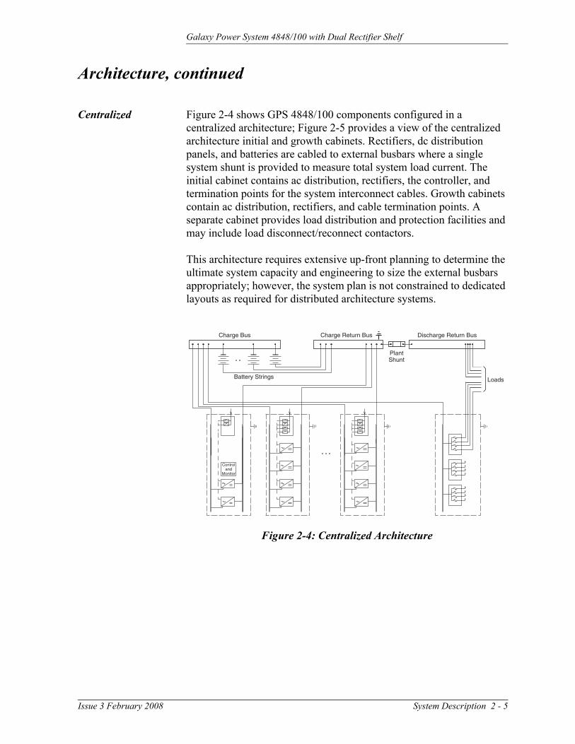
Figure 6-3: H569-434 G32/32A (ED83143-31 G30/30A)Battery Connection Panel
Figure 6-4: H569-434 G34 (ED83143-31 G41)Battery Connection Panel
Terminal Card
Alarm Card
(2) NH3 Fuse Holders
Connects toCharge Return Bus
9" REF(229mm)
Two 600A Shunts
Issue 3 February 2008 Battery Connection Panels 6 - 3

Galaxy Power System 4848/100 with Dual Rectifier Shelf
Figure 6-5: H569-434 G35 (ED83143-31 G42)Battery Connection Panel
Alarm/TerminalCard
(1) NH3 Fuse Holder
Connects toCharge Return Bus
6" REF(152mm)
600A Shunt
Figure 6-6: H569-434 G37/38 (ED83143-31 G60/61)Battery (OLE) Connection Panel
Alarm/Terminal Card
(3) 600A Fuses
(3) 1000A Shunts
(1) 1200A Contactorand Contactor ControlBoard (G60 only)
M10 Connections
Connects toCharge Return Bus
15" REF(381mm)
Note: For more information, referto the OLE Product Manual,Select Code 167-792-200
6 - 4 Battery Connection Panels Issue 3 February 2008

Galaxy Power System 4848/100 with Dual Rectifier Shelf
Figure 6-7: H569-434 G80/81/82 (ED83143-31 G31/43)Battery Connection Panel
Contactor Control Card
AlarmCards
1200A ContactorED83143-31 G31
1200A Contactor
ED83143-31 G43Two NH3 DIN FusesTwo 600A Shunts
Connect toCharge Return Bus
Connect toCharge Return Bus
G80
G81
G82
1 G311 G431 G312 G431 G313 G43 (shown)
H569-434 Includes:
24" REF(610mm)
Issue 3 February 2008 Battery Connection Panels 6 - 5

Galaxy Power System 4848/100 with Dual Rectifier Shelf
Figure 6-8: H569-434 G86/87 (ED83143-31 G63/64)Battery Connection Panel
Alarm Card
Terminal Card800A Contactor
6 Circuit Breaker Positions(Circuit breakers ordered separately)
Shunts (Providedwith circuit breakers)
Connects toCharge Return Bus
12" REF(152mm)
Figure 6-9: H569-434 G39 (ED83143-31 G36)Battery Connection Panel
3000A Shunt
2000A Contactor
Connects toCharge Return Bus
9" REF(229mm)
Contactor Control Card
6 - 6 Battery Connection Panels Issue 3 February 2008

Galaxy Power System 4848/100 with Dual Rectifier Shelf
7 DC Distribution Panels
Overview
Function A variety of dc distribution panels are available featuring large or small fuses and circuit breakers of both domestic and European design. All panels are equipped with an alarm card. When a fuse operates or a circuit breaker trips, a red LED on the alarm card lights, the cabinet alarm lights, and the alarm is transmitted to the controller. Replacement fuses and plug-in circuit breakers are listed in the Replacement Parts section.
Illustrations The dc distribution panels are illustrated in Figures 7-1 through 7-14.
Note: DC distribution panels are white; battery connection panels are blue.
Issue 3 February 2008 DC Distribution Panels 7 - 1

Galaxy Power System 4848/100 with Dual Rectifier Shelf
Figure 7-1: H569-434 G40/45/50/55 (ED83143-31 G11)400A DC Distribution Panel
Alarm/Terminal Card14 Positions for U.S. Plug-inCircuit Breakers or Fuse Holders
Connects toCharge Return Bus
6" REF(152mm)
Figure 7-2: H569-434 G41/46/51/56 (ED83143-31 G12)400A DC Distribution Panel
Alarm/Terminal Card22 Positions for U.S. Plug-inCircuit Breakers or Fuse Holders
Connects toCharge Return Bus
9" REF(229mm)
7 - 2 DC Distribution Panels Issue 3 February 2008

Galaxy Power System 4848/100 with Dual Rectifier Shelf
Figure 7-3: H569-434 G42/47 (ED83143-31 G2)600A DC Distribution Panel
Alarm/Terminal Card 3 Positions for LargeU.S. Circuit Breakerswith Shunts
Connects toCharge Return Bus
6" REF(152mm)
Figure 7-4: H569-434 G43 (ED83143-31 G1)1200A DC Distribution Panel
Alarm Card
Terminal Card
6 Positions for LargeU.S. Circuit Breakerswith Shunts
Connects toCharge Return Bus
12" REF(305mm)
Issue 3 February 2008 DC Distribution Panels 7 - 3
Galaxy Power System 4848/100 with Dual Rectifier Shelf
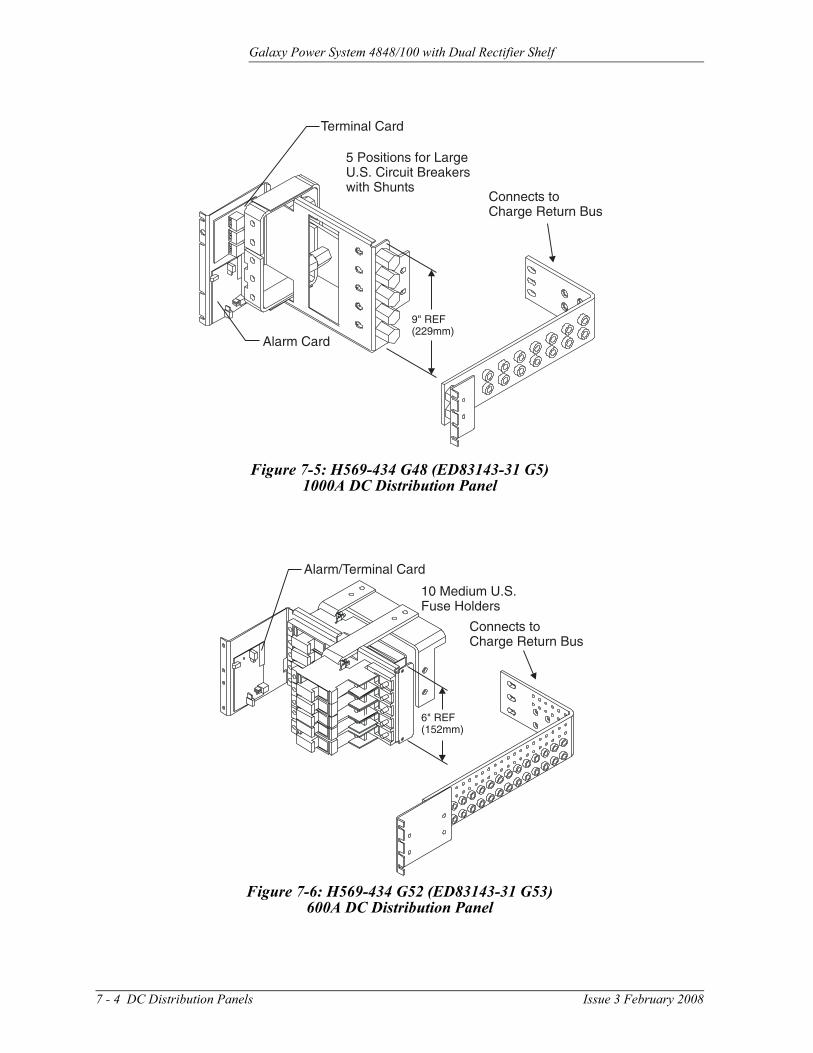
Figure 7-5: H569-434 G48 (ED83143-31 G5)1000A DC Distribution Panel
Alarm Card
5 Positions for LargeU.S. Circuit Breakerswith Shunts
Connects toCharge Return Bus
Terminal Card
9" REF(229mm)
Figure 7-6: H569-434 G52 (ED83143-31 G53)600A DC Distribution Panel
Alarm/Terminal Card
Connects toCharge Return Bus
10 Medium U.S.Fuse Holders
6" REF(152mm)
7 - 4 DC Distribution Panels Issue 3 February 2008
Galaxy Power System 4848/100 with Dual Rectifier Shelf
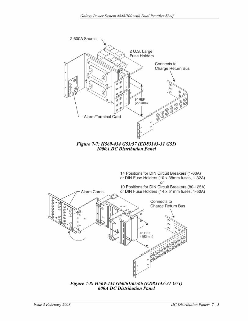
Figure 7-7: H569-434 G53/57 (ED83143-31 G55)1000A DC Distribution Panel
Connects toCharge Return Bus
2 U.S. LargeFuse Holders
2 600A Shunts
Alarm/Terminal Card
9" REF(229mm)
Figure 7-8: H569-434 G60/61/65/66 (ED83143-31 G71)600A DC Distribution Panel
Alarm Cards
14 Positions for DIN Circuit Breakers (1-63A)or DIN Fuse Holders (10 x 38mm fuses, 1-32A)
or10 Positions for DIN Circuit Breakers (80-125A)or DIN Fuse Holders (14 x 51mm fuses, 1-50A)
Connects toCharge Return Bus
6" REF(152mm)
Issue 3 February 2008 DC Distribution Panels 7 - 5

Galaxy Power System 4848/100 with Dual Rectifier Shelf
Figure 7-9: H569-434 G67 (ED83143-31 G22)600A DC Distribution Panel
Alarm/Terminal Card
8 NH00 Fuse Holders
Connects toCharge Return Bus
6" REF(152mm)
Figure 7-10: H569-434 G68 (ED83143-31 G21)1200A DC Distribution Panel
Alarm/Terminal Card
Connects toCharge Return Bus
2 NH2 Fuse Holders
6" REF(152mm)
7 - 6 DC Distribution Panels Issue 3 February 2008

Galaxy Power System 4848/100 with Dual Rectifier Shelf
Figure 7-11: H569-434 G96 (ED83143-31 G15)510A DC Distribution Panel
Alarm/Terminal Card
10 Positions for Plug-in(Bullet Style) Circuit Breakers
Connects toCharge Return Bus
6" REF(152mm)
Figure 7-12: H569-434 G97 (ED83143-31 G16) 14-Position, and H569-434 G98 (ED83143-31 G17) 22-Position DC Distribution Panel
G16: 14 PositionsG17: 22 Positionsfor Plug-in (Bullet Style)Circuit Breakers
Alarm/Terminal Card
Connects toCharge Return Bus
G16: 6" REF (152mm)G17: 9" REF (229mm)
Issue 3 February 2008 DC Distribution Panels 7 - 7

Galaxy Power System 4848/100 with Dual Rectifier Shelf
Figure 7-13: H569-434 G54 (ED83143-31 G54) 5-Position DC Distribution Panel
300A Shunt (in backof panel) per Position
5 Large TPL-BFuse Positions
9" REF(229mm)
Connects toCharge Return Bus
Alarm/Terminal Card
Maximum Panel Capacity1125A800A with LVLD
Figure 7-14: H569-434 G58 (ED83143-31 G58) 6-Position GMT DC Distribution Panel
6 GMT FusePositions
Maximum Panel Ampacity15A per G58 Panel
This panel mounts on the rightside of the GPS cabinet andtherefore takes up no spacewithin the cabinet distributionarea.
6-Pin Jack for Power / AlarmCable Set per 848665147
7 - 8 DC Distribution Panels Issue 3 February 2008

Galaxy Power System 4848/100 with Dual Rectifier Shelf
Figure 7-15: H569-434 G59 (ED83143-31 G56) 2-Position Fuse Distribution Panel
Issue 3 February 2008 DC Distribution Panels 7 - 9


Galaxy Power System 4848/100 with Dual Rectifier Shelf
8 Circuit Boards
Overview
Function Circuit boards (sometimes referred to as “cards” or “circuit packs”) are included in bays, battery connection panels, and dc distribution panels to provide data required by the controller and to control devices such as contactors and lamps.
Terminal Boards Terminal boards are used to provide shunt voltage data to the controller, where it is used to calculate current. Data from the terminal boards located on the battery connection panels are used to calculate battery current; data from terminal boards located on the dc distribution panels are used to calculate load currents.
Alarm Boards Alarm boards perform two functions:
• monitor panel functions and activate local indicators when faults occur on the panel;
• provide alarm data to the controller.
Alarm/Terminal Boards
Alarm/terminal boards combine the functions of alarm boards and terminal boards.
BLJ Terminal Board
The BLJ terminal board is located inside the cabinet door. The BLJ is the termination point for all signal cables in each cabinet and between cabinets.
Issue 3 February 2008 Circuit Boards 8 - 1

Galaxy Power System 4848/100 with Dual Rectifier Shelf
Overview, continued
Bay Interface Card Each cabinet has a Bay Interface Card (BIC) that attaches to the cabinet’s terminal board (BLJ). The BIC provides controller access to alarm monitoring, battery voltages, battery currents, and temperature probes in the cabinet through the serial rectifier bus. The BIC also provides connection of the system serial rectifier bus to the bay rectifiers. See Figure 1-1.
Contactor Control Board
Contactor control boards provide four functions:
• Monitor and report shunt voltage to the controller
• Monitor and report contactor status to the controller
• Operate the contactor based on controller commands
• Operate or block the contactor based on maintenance switch settings
8 - 2 Circuit Boards Issue 3 February 2008

Galaxy Power System 4848/100 with Dual Rectifier Shelf
9 Specifications
GPS 4848/100
Table 9-A: Galaxy Power System 4848/100 Specifications Electrical
Nominal output voltage -48VdcOperating Voltage Range (Float or Boost)
-44Vdc to -58Vdc
Output Current (System Maximum) 14,080ANominal Input Voltage (595LTA or 595A3 Rectifier)
380-480Vac, 3-wire plus ground
Nominal Input Voltage (595LTB or 595B3 Rectifier)
200-240Vac, 3-wire plus ground
Input Voltage Range per phase (595LTA or 595A3 Rectifier)
320Vac - 530Vac
Input Voltage Range per phase (595LTB or 595B3 Rectifier)
176Vac - 254Vac
Input Frequency Range 47 Hz - 63 HzSystem Efficiency (including ac and dc cables)
>88%
Regulation (line and load range with controller)
± 0.5%
AC Ripple <100mVrmsOutput Noise <2mV psophometricElectromagnetic Immunity 10V/meter over 20 MHz - 2000 MHz
Issue 3 February 2008 Specifications 9 - 1

Galaxy Power System 4848/100 with Dual Rectifier Shelf
PhysicalWidth, Depth 600 mm, 600 mm (23.6 in. x 23.6 in.)Weight (approximate, per cabinet) 250 kg (551 lbs.)Height (cabinet only) 2134 mm (84.0 in.)Height (cabinet with link bus bar) 2274 mm (89.5 in.)
EnvironmentalHeat Release, per cabinet
Number of Rectifiers456781214
per Rectifier
at 54Vdc, 220Adc595A / LTA 595B / LTB
4,120W (14,100 BTU / hr) 4,720W (16,100 BTU / hr)5,150W (17,600 BTU / hr) 5,900W (20,200 BTU / hr)6,180W (21,100 BTU / hr) 7,080W (24,200 BTU / hr)7,210W (24,600 BTU / hr) 8,260W (28,200 BTU / hr)8,240W (28,100 BTU / hr) 9,440W (32,200 BTU / hr)12,360W (42,200 BTU / hr) 14,200W (48,300 BTU / hr)14,420W (49,200 BTU / hr) 16,500W (56,400 BTU / hr)1,030W (3,520 BTU / hr) 1,180W (4,050 BTU / hr)
Operating Temperature 0°C to 40°C Operating Relative Humidity 5% - 95%
Units Per Initial CabinetRectifiers 595LTA / 595LTB: 0 - 12; 595A / 595B: 0 - 6Controller 1Battery Modules 0 - 3DC Distribution 1 - 6
(maximum of 5 with battery disconnect)Units Per Growth Cabinet
Rectifiers 595LTA / 595LTB: 0 - 14; 595A / 595B: 0 - 7Battery Modules 0 - 1DC Distribution 1 - 6
(maximum of 5 with battery disconnect)
Table 9-A: Galaxy Power System 4848/100 Specifications (Continued)
9 - 2 Specifications Issue 3 February 2008

Galaxy Power System 4848/100 with Dual Rectifier Shelf
Standards ComplianceSafety • UL3 Listed (US and Canada): UL Subject 1801 with applicable
sections of UL1950/CSA4950)• VDE Licensed to VDE 0805/IEC950/EN60950
3UL is a registered trademark of Underwriters Laboratories, Inc.4CSA is a registered trademark of Canadian Standards Association.
Electromagnetic Compliance • Emission:– FCC Part 15 Class B– EN55022 (CISPR 22) Radiated/Conducted Emission, Class B
• Immunity– IEC/EN 61000-4-2 ESD levels 3 and 4– IEC/EN 61000-4-3 Radiated Immunity, 10V/m– IEC/EN 61000-4-4 Electrical Fast Transients/Burst, level 4– IEC/EN 61000-4-5 Lightning Surge, level 4
CE Marking • CE marked per European Union Council Directives: – Low-Voltage Directive (73/23/EEC)– EMC Directive (89/336/EEC)
as amended by CE Marking Directive (93/68/EEC)Telcordia • GR-63 and GR-1089 NEBS (including Level 3 testing)
• Report by an independent test house
Table 9-A: Galaxy Power System 4848/100 Specifications (Continued)
Issue 3 February 2008 Specifications 9 - 3

Galaxy Power System 4848/100 with Dual Rectifier Shelf
Rectifiers
Table 9-B: 595LT Series Rectifier Specifications Electrical
Output Voltage 52Vdc typicalOutput Voltage Adjustment 44-58Vdc float/boostRegulation (with controller) ±0.5%Output Current 595LTA 595LTB
220A 0°C to 40°C 0°C to 37°CAt 50°C 200A 200A
High Voltage Shutdown (selected by controller)
Float/boost 44-60Vdc (56Vdc default)
Backup High Voltage Shutdown Float/boost 59-60Vdc (59.5Vdc nominal)Ripple 100mVrmsNoise <2mV psophometricCurrent Limit Set Point 60Adc - 220Adc
595LTA Rectifier 595LTB RectifierNominal Input Voltage (3-wire plus ground) 380 - 480 Vac 200 - 240 VacInput Voltage Range (per phase) 320 - 530 Vac 176 - 275VacInput Current Specified
Rated MaximumTypical Maximum
20A at 480Vac 40A at 208Vac25A at 380Vac 35A at 240Vac
30A 50A23.7A at 320Vac 44.1A at 176Vac20.4A at 380Vac 38.8A at 200Vac16.2A at 480Vac 37.3A at 208Vac
32.3A at 240Vac
Frequency Range 47 - 63 HzPower Factor 0.98 from 50% to 100% loadTotal Harmonic Distortion <5% from 50% to 100% loadAC Surge Protection: It is important that ac surges reaching rectifiers do not exceed the capacity of the rectifier internal surge protection. Protection must be provided external to the GPS system to limit surge energy reaching the rectifiers. Site surge protection must be coordinated with rectifier internal surge protection and must clamp at a lower voltage than the rectifier internal protection. The internal protection voltage and current characteristics of the rectifiers are as follows:
595LTAPhase to Phase MOV Conduction
Voltage Current625 Vac (RMS) 0 A940 Vpeak 1 mA1650 Vpeak 100 A
595LTBPhase to Phase MOV Conduction
Voltage Current320 Vac (RMS) 0 A462 Vpeak 1 mA810 Vpeak 100 A
9 - 4 Specifications Issue 3 February 2008

Galaxy Power System 4848/100 with Dual Rectifier Shelf
PhysicalWidth 265 mm (10.4 in.) rear of unitHeight 210 mm (8.25 in.) rear of unitDepth 470 mm (18.2 in.) overall, less connectorWeight 21.5 kg (47.5 lbs)
EnvironmentalEfficiency From 100Adc to 220Adc
595LTA 595LTB >92% >90%
Storage Temperature -40°C - +85°CStorage Relative Humidity 5% - 90%Altitude -50 to 4000 meters (Note: For altitudes above 1500 meters,
derate the temperature by 0.656° Celsius per 100 meters.)Audible Noise < 60dBA at room temperature, mounted in cabinetHeat Release Per Rectifier: 54Vdc, 160Adc 54Vdc, 200Adc 54Vdc, 220Adc
595LTA 595LTB750W (2,560 BTU / hr) 830W (2,800 BTU / hr)940W (3,200 BTU / hr) 1,100W (3,800 BTU / hr)1,000W (3,520 BTU / hr) 1,300W (4,500 BTU / hr)
Standards ComplianceSafety • UL Recognized (US and Canada) and VDE
• UL1950, EN60950/IEC950, and CSA 234/950 (tested for SELV output)
Electromagnetic Compliance:Emission and Immunity
• EN55022 (CISPR22) Radiated/conducted emission, Class B meets FCC Part 15 Class B
• IEC/EN 61000-4-2 ESD levels 3 and 4• IEC/EN61000-4-3 Radiated Immunity, 10Vm• IEC/EN61000-4-4 Electrical Fast Transients/Burst, level 4• IEC/EN 61000-4-5 Lightning Surge, level 4
CE Marking CE marked per European Union Council directives: Low-voltage Directive (73/23/EEC) as amended by CE Marking Directive (93/68/EEC)
Table 9-C: Rectifier Display Messages and LEDsState Display Message LED Illuminated
Normal Current OnOutput Limited Current LIMManual Standby Blank STBYRemote Standby (Shutdown) tr STBYOutput Breaker Open CB ALMInterlock Open ILC ALMAC Fail ACF NonePhase Fail PF NoneOverTemperature Shutdown tA ALMOutput Under Voltage Shutdown LO ALMHigh Voltage Shutdown HO ALMInternal Failure LS, ICS, IP5, IP6, IP7, SEN, FSE, InF ALM
Table 9-B: 595LT Series Rectifier Specifications (Continued)
Issue 3 February 2008 Specifications 9 - 5

Galaxy Power System 4848/100 with Dual Rectifier Shelf
AC Input Panels
Table 9-D: AC PanelsVac AC Feeds Rectifiers ED83142-30 H569-434GPS4848/100
AC Circuit Breaker Panels - 595 Rectifiers208/240 2 4 3 20, 220208/240 2 6 4 21480 1 4 2 22480 2 6 4 23
65KIC 480 2 4 10 70, 27065KIC 480 2 6 11 71
AC Terminal Strip Panels- 595 Rectifiers208/240 4 4 5 24, 224208/240 6 6 5 25208/240 8 8 18 129, 131480 4 4 5 26, 226480 6 6 5 27480 8 8 18 128, 130
AC Circuit Breaker Panels - 595LT Rectifiers208/240 2 4 3 320, 420 208/240 2 6 4 321, 421208/240 4 12 25 335480 1 4 2 322480 2 6 4 323480 4 12 24 334
65KIC 480 2 4 10 370, 47065KIC 480 2 6 11 371, 471
AC Terminal Strip Panels - 595LT Rectifiers208/240 4 4 5 324208/240 6 6 5 325208/240 8 8 18 331208/240 12 12 26 329208/240 14 14 26 333480 4 4 5 326480 6 6 5 327480 8 8 18 330480 12 12 26 328480 14 14 26 332
Distribution Only Panels, no ac- None 28- None 29
9 - 6 Specifications Issue 3 February 2008

Galaxy Power System 4848/100 with Dual Rectifier Shelf
Battery Connection Panels
Table 9-E: Battery Connection PanelsFuse or
Circuit Breaker LVBD Shunt ED83143-31H569-434
GPS4848/100No Battery Panel
None 33
Panels without Fuses or Circuit Breakers1,500A 30 323,000A 30A 32A
2,000A 3,000A 36 391,200A 1,500A 31 312 x 500A 2 x 600A 32 30
Panels with Fuses or Circuit Breakers2 x NH3 fuse 2 x 600A 41 341 x NH3 fuse 600A 42 352 x NH3 fuse 1,200A 2 x 600A 43 with 31 804 x NH3 fuse 1,200A 4 x 600A 2 x 43 with 31 816 x NH3 fuse 1,200A 6 x 600A 3 x 43with 31 826 x breaker poles 63 866 x breaker poles 800A 64 87
Off Line Equalize Panels1,200A 3 x 1,000A 60 37
3 x 1,000A 61 38
Issue 3 February 2008 Specifications 9 - 7

Galaxy Power System 4848/100 with Dual Rectifier Shelf
DC Distribution Panels
Table 9-F: DC Distribution Panels
Fuse or CB Pos Height(in.) LVLD Shunt
ED83143-31Group1
H569-434GPS 4848/100 Group1
CB Clip-on / Fuse Small - TPA 14 6 11 40, 40A, 50, 50ACB Clip-on / Fuse Small - TPA 14 6 Y 11 45, 45A, 55, 55ACB Clip-on / Fuse Small - TPA 22 9 12 41, 41A, 51, 51ACB Clip-on / Fuse Small - TPA 22 9 Y 12 46, 46A, 56, 56A
CB Large – Bolt-in 3 6 CB size, 25mV 2 42, 42A, 106, 106A, 107, 107A, 108, 108A, 109, 109A
CB Large – Bolt-in 3 6 Y CB size, 25mV 2 47, 47A
CB Large – Bolt-in 5 9 CB size, 25mV 5 48, 48A, 110, 110A, 111, 111A, 112, 112A, 113, 113A
CB Large – Bolt-in 5 9 Y CB size, 25mV 5 48B, 48C
CB Large – Bolt-in 6 12 CB size, 25mV 1 43, 43A, 101, 101A, 102, 102A, 103, 103A, 104, 104A
CB Large – Bolt-in 6 12 Y CB size, 25mV 1 43B, 43CCB Bullet 10 6 15 96, 96ACB Bullet 10 6 Y 15 96B, 96CCB Bullet 14 6 16 97, 97ACB Bullet 14 6 Y 16 97B, 97CCB Bullet 22 9 17 98, 98ACB Bullet 22 9 Y 17 98B, 98CFuse Medium - TPS 10 6 53 52, 52AFuse Medium - TPS 10 6 Y 53 52B, 52C
Fuse Large 2 6 1500A, 50mV1 / fuse 56, 56A 59, 59A
Fuse Large - TPL 2 9 600A, 50mV1 / fuse 55 53, 53A
Fuse Large - TPL 2 9 Y 600A, 50mV1 / fuse 55 57, 57A
Fuse Large - TPL-B 5 9 300A, 50mV1 / fuse 54 54, 54A
Fuse Large - TPL-B 5 9 Y 300A, 50mV1 / fuse 54 54B, 54C
CB DIN Small 14 6 71/171 60, 60ACB DIN Small 14 6 Y 71/171 60B, 60CCB DIN Large 10 6 71/171 61, 61ACB DIN Large 10 6 Y 71/171 61B, 61CFuse DIN 10 x 38mm 14 6 71/171 65, 65AFuse DIN 10 x 38mm 14 6 Y 71/171 65B, 65CFuse DIN 14 x 51mm 10 6 71/171 66, 66AFuse DIN 14 x 51mm 10 6 Y 71/171 66B, 66CFuse DIN NH00 8 6 22 67, 67AFuse DIN NH00 8 6 Y 22 67B, 67CFuse DIN NH2 2 6 21 68, 68AFuse DIN NH2 2 6 Y 21 68B, 68CSmall Fuse, 6-GMT 6 0 58 58Blank Panel - 3 JD 93Blank Panel - 6 JA 90Blank Panel - 9 JB 91Blank Panel - 12 JC 921. Groups with B suffix or no suffix include return bus.
Groups with A or C suffix and Blank Panels do not include return bus.
9 - 8 Specifications Issue 3 February 2008

Galaxy Power System 4848/100 with Dual Rectifier Shelf
Issue 3 February 2008 Safety 10 - 1
10 Safety
Please read and follow all safety instructions and warnings before servicing the GPS 4848/100. Reference the Safety section of the GPS Installation Guide and individual module product manuals for safety statements specific to the modules.


Galaxy Power System 4848/100 with Dual Rectifier Shelf
11 Maintenance and Replacement
Requirements
System With the exception of the battery, periodic maintenance specific to the power system is not required. The ac service for the building must be maintained with ANSI specified limits. The temperature and humidity within the power room must be maintained within the limits specified in Section 9 of this product manual.
Refer to Table 11-A for system replacement parts.
Batteries The batteries must be maintained as directed by the battery manufacturer’s requirements.
Controller For replacement circuit packs for the Galaxy Millennium Controller, refer to Table 11-B.
Issue 3 February 2008 Maintenance and Replacement 11 - 1

Galaxy Power System 4848/100 with Dual Rectifier Shelf
Requirements, continued
Rectifier With the exception of a fan failure, rectifiers are repaired by replacement.
Refer to “Installing or Replacing a Rectifier” and “Removing a Rectifier” in this section.
Vacant Rectifier Positions
Vacant rectifier position below or beside the top installed rectifier in this cabinet may cause over-heating of the installed rectifiers. Immediately install a replacement rectifier or a Rectifier Shelf Cover / Air Dam into the vacated position.
Rectifier Shelf Cover(848680211)
Covers both left and right rectifier positions
Air Dam(CC848809178)
Covers the left or right rectifier position
Rectifier Fan Assembly
The expected life of the rectifier fans at 25°C (77°F) is approximately seven years. The fans in the rectifiers may be replaced in the field.
Two approaches can be taken to fan maintenance:
• The first approach is to replace the two fans on a routine basis every six to seven years; this ensures that the fans do not fail in the field under normal operating conditions. This approach is appropriate when there are no remote alarm facilities at the site.
• The second approach, assuming one has remote alarm capability, is to wait until the fans fail. The rectifier will safely shut down and issue both a fail alarm and a fan alarm. The two fans can then be replaced. Since it is likely that all the rectifiers in that installation are of roughly the same age, all rectifier fans at that site should be replaced at that time.
The approach used depends on the location and manning of the site as well as the monitoring of alarms used at the site.
Refer to “Replacing the Rectifier Fan Assemblies” in this section.
11 - 2 Maintenance and Replacement Issue 3 February 2008

Galaxy Power System 4848/100 with Dual Rectifier Shelf
Replacement Procedures
Installing or Replacing a Rectifier
Stop! Be sure rectifier is set to STBY and ac breakers on cabinet are OFF!
Installing or Replacing a RectifierStep Action
1 Unpack the rectifier from shipping container.
CautionRectifier is heavy (47.5 pounds). Use two people to lift and move rectifiers.
2 Remove rectifier by lifting the unit in a vertical direction from the packing container. See figure below.
CautionDo not rest rectifier on faceplate or rear chassis; damage to faceplate and/or rear busbars will occur, rendering the unit unusable.
Lift Straight Up
ABC12345678 Model: 595LTA
480V 48VRECTIFIER
KZO41234567 SX:X
DC
220A/48V
ON
STBY
ALM LIM FANALM
BST
Continued on next page.
Issue 3 February 2008 Maintenance and Replacement 11 - 3

Galaxy Power System 4848/100 with Dual Rectifier Shelf
Replacement Procedures, continued
!
Installing or Replacing a Rectifier, continuedStep Action
3 Turn ac circuit breaker OFF.
4 Place rectifier power switch in STBY.
5 Install the rectifier. See Figure 11-1.
a. Verify that the output circuit breaker is OFF and that the rectifier power switch is in the “Standby” position.
b. Slide the unit slowly onto the shelf until it contacts the rear connector. Note: Install rectifiers, starting at the bottom left position and working to the right, and then upward.
CautionVerify that the rectifier chassis slides rearward evenly on the left and right sides as the locking screw is turned. DO NOT USE EXCESSIVE FORCE DURING THIS PROCEDURE! If the rectifier-to-shelf mating process appears to bind, back the unit out and start over. Avoid stripping the threads of the locking screw by stopping when the rearward progress of the rectifier ceases.
REMOVEBEFOREADDINGSECOND
RECTIFIER
REMOVEBEFOREADDINGSECOND
RECTIFIER
ABC12345678ABC12345678 Model: 595LTA
Model: 595LTA
480V 48VRECTIFIER
KZO41234567 SX:X
DC
220A/48V220A/48V
ON
STBY
ALM LIM FANALMFANALM
BST
Rectifier Shelfin Cabinet
Remove connectorcover to install arectifier into position 2
RectifierPosition 1
Insertion Tool
Figure 11-1: Installing a Rectifier in a Rectifier Shelf
Continued on next page.
11 - 4 Maintenance and Replacement Issue 3 February 2008
Galaxy Power System 4848/100 with Dual Rectifier Shelf
Replacement Procedures, continued
Installing or Replacing a Rectifier, continuedStep Action
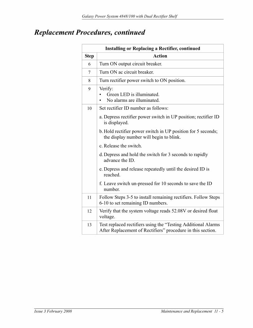
6 Turn ON output circuit breaker.
7 Turn ON ac circuit breaker.
8 Turn rectifier power switch to ON position.
9 Verify:• Green LED is illuminated.• No alarms are illuminated.
10 Set rectifier ID number as follows:
a. Depress rectifier power switch in UP position; rectifier ID is displayed.
b. Hold rectifier power switch in UP position for 5 seconds; the display number will begin to blink.
c. Release the switch.
d. Depress and hold the switch for 3 seconds to rapidly advance the ID.
e. Depress and release repeatedly until the desired ID is reached.
f. Leave switch un-pressed for 10 seconds to save the ID number.
11 Follow Steps 3-5 to install remaining rectifiers. Follow Steps 6-10 to set remaining ID numbers.
12 Verify that the system voltage reads 52.08V or desired float voltage.
13 Test replaced rectifiers using the “Testing Additional Alarms After Replacement of Rectifiers” procedure in this section.
Issue 3 February 2008 Maintenance and Replacement 11 - 5
Galaxy Power System 4848/100 with Dual Rectifier Shelf
Replacement Procedures, continued
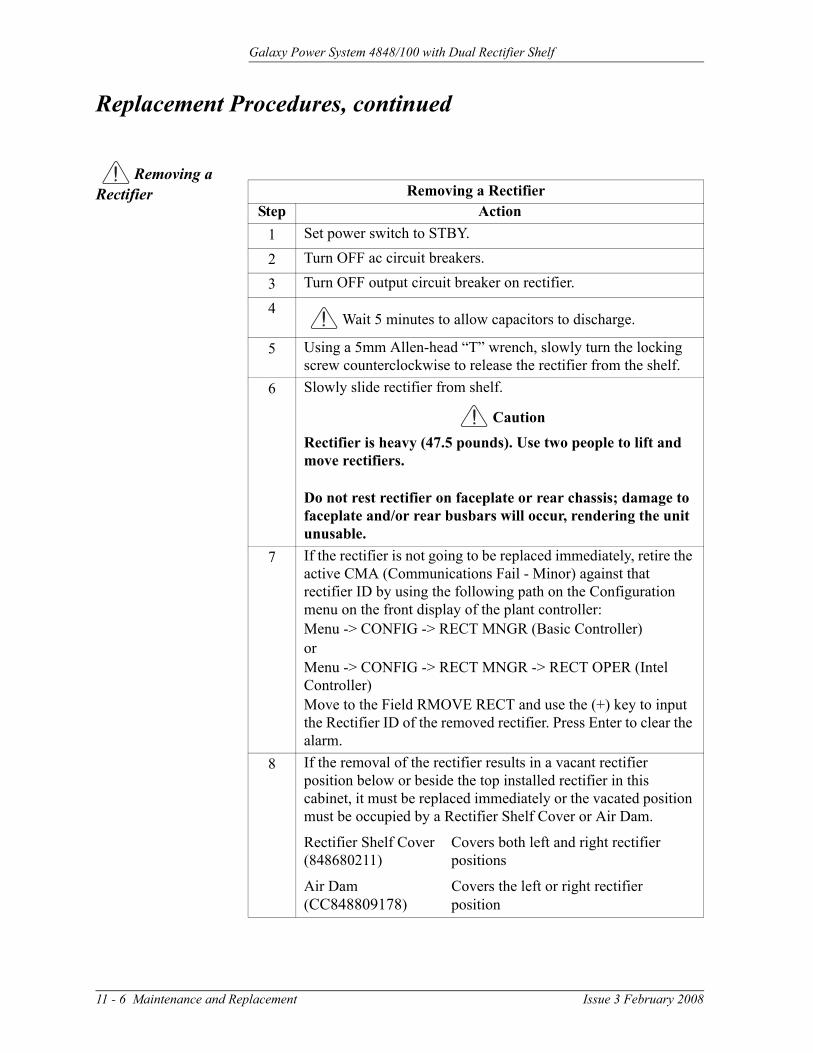
Removing a Rectifier Removing a Rectifier
Step Action1 Set power switch to STBY.
2 Turn OFF ac circuit breakers.
3 Turn OFF output circuit breaker on rectifier.
4Wait 5 minutes to allow capacitors to discharge.
5 Using a 5mm Allen-head “T” wrench, slowly turn the locking screw counterclockwise to release the rectifier from the shelf.
6 Slowly slide rectifier from shelf.
Caution
Rectifier is heavy (47.5 pounds). Use two people to lift and move rectifiers.
Do not rest rectifier on faceplate or rear chassis; damage to faceplate and/or rear busbars will occur, rendering the unit unusable.
7 If the rectifier is not going to be replaced immediately, retire the active CMA (Communications Fail - Minor) against that rectifier ID by using the following path on the Configuration menu on the front display of the plant controller:Menu -> CONFIG -> RECT MNGR (Basic Controller)orMenu -> CONFIG -> RECT MNGR -> RECT OPER (Intel Controller)Move to the Field RMOVE RECT and use the (+) key to input the Rectifier ID of the removed rectifier. Press Enter to clear the alarm.
8 If the removal of the rectifier results in a vacant rectifier position below or beside the top installed rectifier in this cabinet, it must be replaced immediately or the vacated position must be occupied by a Rectifier Shelf Cover or Air Dam.
Rectifier Shelf Cover Covers both left and right rectifier (848680211) positions
Air Dam Covers the left or right rectifier(CC848809178) position
11 - 6 Maintenance and Replacement Issue 3 February 2008

Galaxy Power System 4848/100 with Dual Rectifier Shelf
Replacement Procedures, continued
Replacing the Rectifier Fan Assemblies
Replacing the Rectifier Fan AssembliesStep Action
1 Follow instructions in the “Removing a Rectifier” procedure in this section. Refer to Figure 11-1.
2 Place rectifier on a flat surface at a comfortable working height.
3 Loosen the front cover (white) by removing 4 screws (2 on each side). Remove the cover and place it next to the rectifier. See Figure 11-2.
CautionAllow the front end of the rectifier to overhang the working surface.
Fan Cable Clamp
Figure 11-2: Rectifier Faceplate Assembly
Continued on next page.
Issue 3 February 2008 Maintenance and Replacement 11 - 7

Galaxy Power System 4848/100 with Dual Rectifier Shelf
Replacement Procedures, continued
Replacing the Rectifier Fan Assemblies, continuedStep Action
4 Carefully unplug the fan connectors (2). The fan connector is keyed and can be loosened by inserting a screwdriver into the slotted side of the connector and gently prying the fan-side connector loose.
5 Remove the fan cable clamp.
6 Place the new fans in position with their cables positioned as shown in Figure 11-3.
7 Replace the fan cable clamp.
8 Replace the front cover.
9 Install the rectifier, following the “Installing or Replacing a Rectifier” procedure in this section.
10 Test replaced rectifiers using the “Testing Additional Alarms After Replacement of Rectifiers” procedure in this section.
Figure 11-3: Rectifier Fan Assembly
Fan Cable Clamp
Fans
11 - 8 Maintenance and Replacement Issue 3 February 2008

Galaxy Power System 4848/100 with Dual Rectifier Shelf
Testing Note: Consult the GPS Installation Guide for complete testing guidelines for new installations. Alarm LEDs refer to the controller unless otherwise noted.
Testing Additional Alarms After Replacing Rectifiers
Alarm operation may be verified while the system operates at float voltage.
Testing Additional Alarms After Replacing RectifiersStep Action
1 Turn OFF the ac circuit breaker of replaced rectifier. Verify that AC and MIN alarm LEDs illuminate, the rectifier displays ACF, and the controller alarms screen indicates AC FAIL: Gmm.
2 Turn ON the ac circuit breaker of the replaced rectifier. Verify that the rectifier starts and the alarms retire.
3 Turn OFF the DC Output CB at the bottom left of the rectifier. Verify that the Rectifier and Minor alarm LEDs illuminate, the rectifier displays Cb, and the controller alarms screen indicates RECTIFIER FAIL: Gmm.
4 Turn ON the DC Output CB of the rectifier. Verify that the rectifier picks up load similar to others in the system and that the alarms retire.
Testing Rectifiers and Load Share in Bay Expansions Testing Rectifiers and Load Share in Bay Extensions
Step Action1 Turn all rectifiers to STBY.
2 Connect a resistive load box (proper voltage) to the system’s positive and negative bus bars.
3 Verify that the system load is less than 50 amperes.
4 Increase the system load to 200 amperes.
5 Turn ON all the rectifiers; after approximately 60 seconds, verify that the load is divided equally among all the rectifiers (within 2 amperes).
6 Reduce the system load. Verify that the rectifiers continue to share the load.
7 Remove system load.
Issue 3 February 2008 Maintenance and Replacement 11 - 9

Galaxy Power System 4848/100 with Dual Rectifier Shelf
Replacement Parts
System Table 11-A provides a list of replacement parts for GPS 4848/100.
Table 11-A: GPS 4848/100 Replacement Parts
Ordering Comcode DescriptionCabinet
406204230 3 ampere alarm fuse402328926 0.18 ampere alarm fuse406530725 1-1/3 ampere alarm fuse405673161 1/2 ampere panel alarm fuse (WP90247 L3)406420273 GMT fuse puller tool 848262622 BLJ3 terminal board408229318 Wire insertion tool848703419 BIC9 bay interface card107900169 EBV2 load disconnect board107604076 BJN1 battery disconnect board407226786 Lens cover, red407227172 Cabinet alarm lamp, 48V
Rectifier and Rectifier Shelf
108972238 595LTA, 220 ampere rectifier108990405 595LTB, 220 ampere rectifier848693586 Fan (2 Required)901181834 Insulated Allen-head wrench
Distribution
405673161 1/2 ampere alarm fuseGalaxy Millennium Controller
406677880 Battery TL5101 for BSJ406530725 1-1/3 ampere fuse (GMT)406204230 3 ampere fuse (GMT)
11 - 10 Maintenance and Replacement Issue 3 February 2008

Galaxy Power System 4848/100 with Dual Rectifier Shelf
Replacement Parts, continued
Millennium Controller Circuit Boards
Table 11-B lists the spare parts of the Galaxy Millennium Controller.
Table 11-B: Galaxy Millennium Controller Circuit Boards
Ordering Comcode Description
108029679 Display board (BSK1)108029687 Alarm wire wrap board (BSL1)848194551 Insulation displacement alarm board (BSL2)108029653 Basic control board (BSH1) 847950912 LCD module assembly display board108029661 Intelligent control board (BSJ1)108851338 Modem board (BSM5)108163601 Data switch board (BSW1)108340100 Gateway board (EBW1)
Additional Ordering Information
Documentation Table 11-C lists documentation associated with the GPS 4848/100.
Table 11-C: Product Documentation
Document Number Description
H569-434 GPS 4848/100 Ordering Guide167-792-157 GPS Installation Guide167-792-180 Galaxy Millennium Controller Product Manual
167-790-063 Remote Peripheral Monitoring System Product Manual
193-104-105 EasyView Software Product Manual193-104-106 Galaxy Gateway Product Manual
Software EasyView software is a Windows-compatible communications package designed specifically for use with Galaxy controllers. Download EasyView software from http://www.lineagepower.com. Click “Downloads” and click on the appropriate EasyView download button.
Issue 3 February 2008 Maintenance and Replacement 11 - 11


Galaxy Power System 4848/100 with Dual Rectifier Shelf
12 Troubleshooting Preparations
Preliminary
Introduction This section provides information needed in preparation for locating and interpreting visual indicators to help identify problems.
When replacing a part does not correct the problem or visual indicators do not identify a defective part, notify Lineage Power Technical Support.
Safety Review all safety instructions and warnings in the Safety section of the GPS Installation Guide before troubleshooting the GPS 4848/100.
Warning
Hazardous ac and dc voltages and/or energy are present. Caution should be exercised. Tools must be insulated to help prevent accidental contact with live surfaces.
Coordinate all troubleshooting activities with other personnel that may be working on the system.
Tools The following tools are necessary in order to troubleshoot the GPS 4848/100:
• 3/16-inch (5 mm) Allen-head wrench• Insulated hand tools• Calibrated digital voltmeter (DVM)
(0.05% accuracy on dc scale)• ESD wrist strap
Issue 3 February 2008 Troubleshooting Preparations 12 - 1

Galaxy Power System 4848/100 with Dual Rectifier Shelf
Troubleshooting Procedure
Purpose The troubleshooting procedure described below is used when a trouble condition has been identified and a technician has been dispatched to the system location as a first and fundamental step in diagnosing and correcting the problem.
For all trouble conditions, proceed as follows:
Cabinet Alarm 1. Locate the system controller. The controller is typically located in the cabinet identified as BAY ONE. Because a trouble condition exists, the red alarm on the top of the cabinet will be illuminated. See Figure 12-1.).
Figure 12-1: Location of Cabinet Alarm Light and Controller
GalaxyMillenniumController
Cabinet Alarm Light
12 - 2 Troubleshooting Preparations Issue 3 February 2008

Galaxy Power System 4848/100 with Dual Rectifier Shelf
Troubleshooting Procedure, continued
System Status 2. Determine the system status. For most problems, one or more alarm and status LEDs will be illuminated. The controller default screen indicates system voltage and current, the system mode (i.e., FLOAT or EQUALIZE), and the number of alarms and/or warnings present.
If the screen is blank, but alarm and status LEDs are illuminated, call technical support. If the entire panel is blank, check the F3 basic power fuse (Figure 12-3). Verify that the controller is getting power. If not, replace fuse. If the display is still blank, call technical support.
Alarms Menu 3. If the default screen appears normal, press the MENU button. The main menu appears with “Alarms” blinking. Press ENTER to obtain the Alarms menu. Additional data appears that will help to identify the problem.
Troubleshooting Tables
4. Based on the information presented by the alarm LEDs, select the appropriate table from the list below:
Section 13, Troubleshooting Millennium SystemsAlarm LED Table
AC 13-A, AC AlarmsBATT 13-B, Battery AlarmsBD 13-F, Miscellaneous AlarmsCTRL 13-C, Controller AlarmsDIST 13-D, Distribution AlarmsRECT 13-E, Rectifier Related AlarmsNo LED* 13-F, Miscellaneous Alarms*If an alarm condition exists, but no alarm LED is lit, refer to Table 13-F.
Identifying Problems
5. Once the appropriate table is identified, use the status LEDs and the alarm menu data to identify the specific problem that is causing the alarm.
Issue 3 February 2008 Troubleshooting Preparations 12 - 3

Galaxy Power System 4848/100 with Dual Rectifier Shelf
Reference Figures
Figure Numbers and Titles
The following figures are provided for reference while performing the troubleshooting procedure:
Figure No. Title12-1 Location of Cabinet Alarm Light and Controller12-2 Millennium Controller Display12-3 Millennium Controller Fuses and Circuit Boards12-4 Rectifier Display
12-5 Low Voltage Battery Disconnect Contactor Control Switches
12-6 AC Input Panel and Rectifier Connection12-8 DC Distribution Panel
12-9 Low Voltage Load Disconnect Contactor Control Switches
Millennium Controller
Basic Controller
BSH (microprocessor board): After power up, or after a reset, the green and yellow LEDs will both be lit while self diagnostics are in progress (which will take about 10 seconds). If all diagnostics pass, the yellow LED will extinguish and the green LED will remain lit. If a failure is detected during diagnostics, the green LED will extinguish and the yellow LED will remain lit.
If a failure occurs during normal operation, the green LED will extinguish and the yellow LED will light.
Intelligent Controller
BSJ (microprocessor board): After power up, or after a reset, the green and yellow LEDs will both be lit while self diagnostics are in progress (which will take about 30 seconds). If all diagnostics pass, the yellow LED will extinguish and the green LED will remain lit. If a failure is detected during diagnostics, the green LED will extinguish and the yellow LED will remain lit. If a terminal is attached to the local port during diagnostics, the diagnostic messages will show which test failed.
If a failure occurs during normal operation, the green LED will extinguish and the yellow LED will light.
12 - 4 Troubleshooting Preparations Issue 3 February 2008

Galaxy Power System 4848/100 with Dual Rectifier Shelf
Reference Figures, continued
Millennium Controller, continued
Figure 12-2: Millennium Controller Display
Galaxy Millennium ControllerAlarm Status
Critical
Escape Help
EnterMenu
Equipment Status
AC System
Battery
Controller
Distribution
Rectifier
RemoteModules
Major
Minor
Normal
Battery onDischarge
V
Figure 12-3: Millennium Controller Fuses and Circuit Boards
BSM Modem Board
Intelligent LEDsBasic LEDs
BSH Basic Controller Board BSJ Intelligent Controller Board
BSL Alarm Termination Board
BSW Data Switch Board(mounting location)
Controller FusesF1 - Peripheral Monitor PowerF2 - Intelligent PowerF3 - Basic PowerF4 - Voltage SenseF5 - Alarm Battery Supply
F1 F2 F3 F4 F5
GMTFuses
3A
1 1/3A
Issue 3 February 2008 Troubleshooting Preparations 12 - 5

Galaxy Power System 4848/100 with Dual Rectifier Shelf
Reference Figures, continued
Rectifier During normal operation, the rectifier’s green ON LED will be lit and the display will show the rectifier’s output current.
Figure 12-4: Rectifier Display
Status Indicators
ABC12345678Model: 595LTA
480V 48VRECTIFIERKZO41234567 SX:X
DC
220A/48V
ON
STBY ALM LIM FANALM
BST
ALM FANALM
LIM BST
12 - 6 Troubleshooting Preparations Issue 3 February 2008

Galaxy Power System 4848/100 with Dual Rectifier Shelf
Reference Figures, continued
Low Voltage Battery Disconnect
The low voltage battery disconnect (LVBD) feature consists of a contactor, circuitry on the BJN board, and associated wiring. Control of the contactor is dictated by the BJN contactor control board and the controller.
Figure 12-5: Low Voltage Battery Disconnect Contactor Control Switches
Red Light
Yellow Light
Green Light
CONTACTOR DRIVE BOARD
SW
SW
SW
BOTH SWITCHES DOWNFORCES CONTACTOR OPEN
CONTACTOR OPEN
CONTACTOR OPEN INITIATED
DOWN FORCESCONTACTOR CLOSED
REMOTE CONTROL ENABLED
Note: All switches should be in theup position for normal operation.
Issue 3 February 2008 Troubleshooting Preparations 12 - 7

Galaxy Power System 4848/100 with Dual Rectifier Shelf
Reference Figures, continued
AC Input
Figure 12-6: AC Input Panel and Rectifier Positions, 6 Rectifiers
12 - 8 Troubleshooting Preparations Issue 3 February 2008
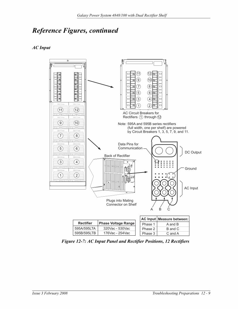
Galaxy Power System 4848/100 with Dual Rectifier Shelf
Reference Figures, continued
AC Input
Figure 12-7: AC Input Panel and Rectifier Positions, 12 Rectifiers
Issue 3 February 2008 Troubleshooting Preparations 12 - 9

Galaxy Power System 4848/100 with Dual Rectifier Shelf
Reference Figures, continued
DC Distribution
Figure 12-8: DC Distribution Panel
Connects to NegativeCharge Bus
Alarm LED
Alarm/Terminal Card
Alarm/Terminal Card
Connects toCharge Return Bus
12 - 10 Troubleshooting Preparations Issue 3 February 2008

Galaxy Power System 4848/100 with Dual Rectifier Shelf
Reference Figures, continued
Low Voltage Load Disconnect
The EBV low voltage load disconnect (LVLD) contactor control board is mounted on the right side of the cabinet, as shown in Figure 12-9.
The manual contactor control switch (SW300) is not meant to be used to permanently override the LVLD function. It is only to be used temporarily while servicing or testing the equipment.
Figure 12-9: Low Voltage Load Disconnect ContactorControl Switches
Note: Switch should be in thedown position for normal operation.
Red Light
Yellow Light
Green Light
UP POSITION FORCESCONTACTOR CLOSED
REMOTE CONTROLENABLED
CONTROLLER SIGNALERROR DETECTED
CONTROLLER SIGNALOPENED CONTACTOR
GREEN LIGHT
YELLOW LIGHT ONLY
RED AND YELLOW LIGHT
LOAD DISCONNECT FEATURE IS NOT
FOR USE IN BATTERYLESS SYSTEMS
REMOTECONTROLOVERRIDESWITCH
Control switch mountedon right side of cabinet.
Issue 3 February 2008 Troubleshooting Preparations 12 - 11


Galaxy Power System 4848/100 with Dual Rectifier Shelf
13 Troubleshooting Millennium Systems
Introduction
In This Section This section provides information for locating and interpreting visual indicators to help identify problems.
Preparation Read Section 12, Troubleshooting Preparations, thoroughly before proceeding.
Technical Assistance
When visual indicators do not identify a defective part, notify Lineage Power Technical Support.
Issue 3 February 2008 Troubleshooting Millennium Systems 13 - 1

Galaxy Power System 4848/100 with Dual Rectifier Shelf
Troubleshooting Tables
Organization The tables in this section are organized alphabetically by Alarm LED, then grouped according to the status of the alarm: Critical (CRIT), Major (MAJ), or Minor (MIN).
Table Reference Use the reference below to locate the Alarm LED and corresponding table.
Controller Alarm LED TableAC 13-A, AC AlarmsBATT 13-B, Battery AlarmsBD 13-F, Miscellaneous AlarmsCTRL 13-C, Controller AlarmsDIST 13-D, Distribution AlarmsRECT 13-E, Rectifier Related AlarmsRM 13-F, Miscellaneous AlarmsNo LED* 13-F, Miscellaneous Alarms*If an alarm condition exists, but no alarm LED is lit, refer to
Table 13-F.
Rectifier Display Messages and LEDs State Display Message LED Illuminated
Normal Current OnOutput Limited Current LIMManual Standby Blank STBYRemote Standby (Shutdown)
tr STBY
Output Breaker Open CB ALMInterlock Open ILC ALMAC Fail ACF NonePhase Fail PF NoneOverTemperature Shutdown
tA ALM
Output Under Voltage Shutdown
LO ALM
High Voltage Shutdown HO ALMInternal Failure LS, ICS, IP5, IP6, IP7,
SEN, FSE, InFALM
13 - 2 Troubleshooting Millennium Systems Issue 3 February 2008

Galaxy Power System 4848/100 with Dual Rectifier Shelf
Millennium Controller Display
The Millennium display is illustrated below.
Galaxy Millennium ControllerAlarm Status
Critical
Escape Help
EnterMenu
Equipment Status
AC System
Battery
Controller
Distribution
Rectifier
RemoteModules
Major
Minor
Normal
Battery onDischarge
V
AC Alarm LED
Table 13-A: AC Alarms(See Figure 12-6)
Controller LED
Controller Alarm Status
Millennium Controller Display
Other Indication(s) Possible Problem(s) Possible Solution(s)
AC MIN AC Fail ACF on rectifier display
Rectifier is not receiving ac power:•AC input circuit breaker has operated.
•AC input voltage is out of range.
•Internal rectifier failure
1. Verify that ac circuit breaker is closed; close circuit breaker if operated.
2. If the problem is not corrected, replace the rectifier.
AC MIN Engine Transfer Timeout
Engine may have alarm.
Remote engine or connection to engine has failed.
Call technical support.
AC MIN Phase Alarm PF on rectifier display
Phase failure:•Rectifier high voltage shutdown
•External phase imbalance or failure
•Internal rectifier failure
1. Toggle the ON/STBY switch into the STBY position and then back into the ON position.
2. If the problem is not corrected, replace the rectifier.
Issue 3 February 2008 Troubleshooting Millennium Systems 13 - 3

Galaxy Power System 4848/100 with Dual Rectifier Shelf
BATT Alarm LED
Table 13-B: Battery Alarms(See Figure 12-5)
Controller LED
Controller Alarm Status
Millennium Controller Display
Other Indication(s) Possible Problem(s) Possible Solution(s)
BATT CRIT Very Low Voltage -- Occurs in an operating system following an extended commercial ac power outage, during which the batteries are providing power for the system and the system voltage is approaching the user-defined low limit.
1. If commercial ac power is present but the system voltage remains low, call technical support.
2. Investigate other alarms that may be present (rectifier-related alarms and the AC Fail alarm may also occur during the fault condition).
BATT**Alarm must be configured to turn on the BATT LED; not a factory default.
MAJ Contactor 1 Open Red LED on contactor drive board is lit.
Contactor is open:•Open has been initiated by controller.
•Open has been initiated manually.
1. Follow instructions on the label adjacent to the contactor drive board (see Figure 12-5).
2. If the problem is not corrected, call technical support.
BATT**Alarm must be configured to turn on the BATT LED; not a factory default.
MAJ Contactor 1 Fail -- Contactor or drive board has failed.
Call technical support.
BATT MIN Open String Alarm LED on battery fuse panel is lit.
Battery fuse has operated.
Replace the operated fuse.
BATT MIN Low Reserve Time -- Controller has calculated that batteries are low.
Call technical support.
13 - 4 Troubleshooting Millennium Systems Issue 3 February 2008

Galaxy Power System 4848/100 with Dual Rectifier Shelf
CTRL Alarm LED
Table 13-C: Controller Alarms (See Figures 12-2 and 12-3)
Controller LED
Controller Alarm Status
Millennium Controller Display
Other Indication(s) Possible Problem(s) Possible Solution(s)
CTRL MAJ Controller Fail -- •BSH failure→
•BSJ failure•Option board failure
•Display failure•BIC failure
Check the BSH board to see if the green LED is extinguished and the yellow LED is lit. If so, perform the following steps:1. Press the SW200 reset
switch on the top of the BSH board. If all diagnostics pass, it is possible that some type of “one time” abnormality occurred to cause the failure.
2. If the diagnostics did not pass, or if the problem recurs, unplug all the optional circuit board cables, then press the reset switch on the top of the BSH board again. If all the diagnostics pass, install optional circuit board cables one at a time, verifying operation after each.
3. If the diagnostics did not pass, replace the BSH board and verify the failure is resolved. If so, reinstall the optional circuit boards and cables one at a time.
4. If the problem is not corrected, call technical support.
Issue 3 February 2008 Troubleshooting Millennium Systems 13 - 5

Galaxy Power System 4848/100 with Dual Rectifier Shelf
CTRL MAJ Controller Fail -- •BSH failure•BSJ failure→
•Option board failure
•Display failure•BIC failure
Check the BSJ board to see if the green LED is extinguished and the yellow LED is lit. If so, perform the following steps:1. Press the SW201 reset
switch on the top of the BSJ board. (This circuit has an automatic restart, which will try three times to restart the microprocessor.)
2. If the diagnostics did not pass, or if the problem recurs, remove all the optional circuit board cables, then press the reset switch on the top of the BSJ board again. If all the diagnostics pass, install optional circuit board cables one at a time, verifying operation after each.
3. If the diagnostics did not pass, replace the BSJ board and verify the failure is resolved. If so, reinstall the optional circuit boards and cables one at a time.
4. If the problem is not corrected, call technical support.
Table 13-C: Controller Alarms (Continued)(See Figures 12-2 and 12-3)
Controller LED
Controller Alarm Status
Millennium Controller Display
Other Indication(s) Possible Problem(s) Possible Solution(s)
13 - 6 Troubleshooting Millennium Systems Issue 3 February 2008

Galaxy Power System 4848/100 with Dual Rectifier Shelf
CTRL MAJ Controller Fail -- •BSH failure•BSJ failure•Option board failure→
•Display failure•BIC failure
Check the option boards (modem and data switch) to see if the green LED is extinguished and the yellow LED is lit. If so, perform the following steps:1. Press the SW201 reset
switch on the top of the BSJ board. (This circuit has an automatic restart, which will try three times to restart the microprocessor.) If the BSJ is not present, press the reset switch on the top of the BSH board.
2. If the diagnostics did not pass, or if the problem recurs, replace the failed option board.
CTRL MAJ Controller Fail -- •BSH failure•BSJ failure•Option board failure
•Display failure→
•BIC failure
If the front panel LCD module, LEDs, or switches fail, perform the following steps:1. Verify that the ribbon
cable from the BSH board to the display is not cut, abraded, or otherwise mangled. Replace the cable if damaged.
2. Press SW200 to reset the BSH board.
3. If the LCD module is still not operating, replace the LCD module; if the switches and LEDs are still not operating, replace the BSH board.
Table 13-C: Controller Alarms (Continued)(See Figures 12-2 and 12-3)
Controller LED
Controller Alarm Status
Millennium Controller Display
Other Indication(s) Possible Problem(s) Possible Solution(s)
Issue 3 February 2008 Troubleshooting Millennium Systems 13 - 7

Galaxy Power System 4848/100 with Dual Rectifier Shelf
CTRL MAJ Controller Fail -- •BSH failure•BSJ failure•Option board failure
•Display failure•BIC failure→
1. Strap K1, K2, K3 on BLJ from “C” to “R” prior to replacing BIC. See Figure 8-2.
2. Replace BIC.
CTRL MAJ Circuit Pack Fail -- See “Controller Fail”.
See “Controller Fail”.
CTRL MAJ Controller Fuse -- Fuse has operated. Replace the controller fuse labeled F2 (intelligent power).
CTRL MAJ Alarm Battery Supply Fuse
-- Fuse has operated. Replace the controller fuse labeled F5 (alarm battery supply).
CTRL MAJ Remote Peripheral Fuse
-- Fuse has operated. Replace the controller fuse labeled F1 (option power).
CTRL MAJ Sense/Control Fuse
-- Fuse has operated. Replace the controller fuse labeled F4 (voltage sense).
CTRL MAJ Bay Interface ID Conflict
-- Two or more bay interface cards (BICs) have the same ID number.
Following instructions printed on the label over the BIC, adjust the DIP switches to change the ID number.
CTRL MAJ Major Communication Fail Alarm
Blinking ALM LED on rectifiers orred LED on BIC
Loss of communication with controller:•Defective interface from BIC or multiple rectifiers to controller
•Internal failure of controller, BIC, or multiple rectifiers
1. Verify that the controller is powered and operating correctly.
2. If there are no controller alarms, replace the equipment that has lost communication.
3. If the problem is not corrected, call technical support.
Table 13-C: Controller Alarms (Continued)(See Figures 12-2 and 12-3)
Controller LED
Controller Alarm Status
Millennium Controller Display
Other Indication(s) Possible Problem(s) Possible Solution(s)
13 - 8 Troubleshooting Millennium Systems Issue 3 February 2008

Galaxy Power System 4848/100 with Dual Rectifier Shelf
DIST Alarm LEDTable 13-D: Distribution Alarms
(See Figures 12-7 and 12-8)
Controller LED
Controller Alarm Status
Millennium Controller Display
Other Indication(s)
Possible Problem(s) Possible Solution(s)
DIST MAJ External Fuse Major
Alarm LED on dc distribution panel is lit.
DC load fuse or circuit breaker has operated.
Replace fuse or reset circuit breaker.
DIST**Alarm must be configured to turn on the DIST LED; not a factory default.
MAJ Contactor 2 (or 3) Open
Red LED on contactor drive board is lit.
Contactor is open:•Open has been initiated by controller.
•Open has been initiated manually.
1. Follow instructions on the label adjacent to the contactor drive board (see Figure 12-8).
2. If the problem is not corrected, call technical support.
DIST**Alarm must be configured to turn on the DIST LED; not a factory default.
MAJ Contactor 2 (or 3) Fail
-- Contactor or drive board has failed.
Call technical support.
CTRL MIN Minor Communication Fail Alarm
Blinking ALM LED on rectifier
Loss of communication with controller:•Defective interface from rectifier to controller
•Internal controller or rectifier failure
1. Verify that the controller is powered and operating correctly.
2. If there are no controller alarms, replace the equipment that has lost communication.
3. If the problem is not corrected, call technical support.
CTRL MIN Self Fail Test -- See “Controller Fail”.
See “Controller Fail”.
CTRL MIN Thermal Probe Failure
-- Battery thermal probe has failed.
Call technical support.
Table 13-C: Controller Alarms (Continued)(See Figures 12-2 and 12-3)
Controller LED
Controller Alarm Status
Millennium Controller Display
Other Indication(s) Possible Problem(s) Possible Solution(s)
Issue 3 February 2008 Troubleshooting Millennium Systems 13 - 9

Galaxy Power System 4848/100 with Dual Rectifier Shelf
RECT Alarm LED
Table 13-E: Rectifier Related Alarms (See Figures 12-4 and 12-6)
Controller LED
Controller Alarm Status
Millennium Controller Display
Rectifier LED
Rectifier Display
Possible Problem(s) Possible Solution(s)
RECT MAJ ID Not Configured None None Rectifier ID number has not been set.
Set rectifier ID using procedure in Section 11, “Installing or Replacing a Rectifier.”
RECT MAJ ID Conflict None None Two or more rectifiers have the same ID number.
See above.
RECT MAJ Multiple Rectifier Fail
ALM None More than one rectifier has an ALM LED lit.
See alarms listed below.
RECT MAJ High Voltage Alarm
ALM HO •Lightning has struck system.
•Internal rectifier failure
1. Toggle the ON/STBY switch into the STBY position and then back into the ON position.
2. If the problem is not corrected, replace the rectifier.
RECT MIN Rectifier Fail ALM HO High output voltage:•Rectifier high voltage shutdown
•Internal rectifier failure
1. Verify the configurable HV thresholds in the controller.
2. Toggle the ON/STBY switch into the STBY position and then back into the ON position.
3. If the problem is not corrected, replace the rectifier.
13 - 10 Troubleshooting Millennium Systems Issue 3 February 2008
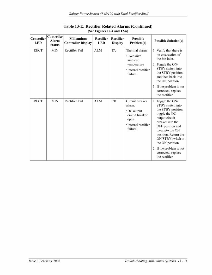
Galaxy Power System 4848/100 with Dual Rectifier Shelf
RECT MIN Rectifier Fail ALM TA Thermal alarm:•Excessive ambient temperature
•Internal rectifier failure
1. Verify that there is no obstruction of the fan inlet.
2. Toggle the ON/STBY switch into the STBY position and then back into the ON position.
3. If the problem is not corrected, replace the rectifier.
RECT MIN Rectifier Fail ALM CB Circuit breaker alarm:•DC output circuit breaker open
•Internal rectifier failure
1. Toggle the ON/STBY switch into the STBY position; toggle the DC output circuit breaker into the OFF position and then into the ON position. Return the ON/STBY switch to the ON position.
2. If the problem is not corrected, replace the rectifier.
Table 13-E: Rectifier Related Alarms (Continued)(See Figures 12-4 and 12-6)
Controller LED
Controller Alarm Status
Millennium Controller Display
Rectifier LED
Rectifier Display
Possible Problem(s) Possible Solution(s)
Issue 3 February 2008 Troubleshooting Millennium Systems 13 - 11

Galaxy Power System 4848/100 with Dual Rectifier Shelf
RECT MIN Rectifier Fail ALM ICSIP5IP6IP7InFFSELS
Internal rectifier failure
1. Place the ac circuit breaker for the rectifier in the OFF position.
2. Remove the rectifier from the shelf.
3. Wait for 30 seconds or until all front panel display LEDs have extinguished.
4. Replace the rectifier.
5. Return the ac breaker to the ON position.
6. Place the rectifier ON/STBY switch into the ON position.
7. If the problem is not corrected, replace the rectifier.
RECT MIN Rectifier Fail ALM LO Low output voltage:•Excessive output current
•Internal rectifier failure
1. Toggle the ON/STBY switch into the STBY position and then back into the ON position.
2. If the problem is not corrected, replace the rectifier.
Table 13-E: Rectifier Related Alarms (Continued)(See Figures 12-4 and 12-6)
Controller LED
Controller Alarm Status
Millennium Controller Display
Rectifier LED
Rectifier Display
Possible Problem(s) Possible Solution(s)
13 - 12 Troubleshooting Millennium Systems Issue 3 February 2008

Galaxy Power System 4848/100 with Dual Rectifier Shelf
RECT MIN Rectifier Fail ALM SEN Thermal sensor failure:•Internal rectifier failure
1. Place the ac circuit breaker for the rectifier in the OFF position.
2. Remove the rectifier from the shelf.
3. Wait for 30 seconds or until all front panel display LEDs have extinguished.
4. Replace the rectifier.
5. Return the ac breaker to the ON position.
6. Place the rectifier ON/STBY switch into the ON position.
7. If the problem is not corrected, replace the rectifier with a new one.
RECT MIN Rectifier Fail FAN ALM
None Fan failure Replace the fan in the rectifier.
RECT MIN Manual Off STBY Blank Rectifier has been manually turned off.
Turn rectifier on.
RECT MIN External Transfer Shutdown
STBY TR System is operating on external engine.
No action required.
RECT MIN High Float Voltage None None Configuration problem
Call technical support.
RECT MIN Excess Rectifier Drain
None None Internal rectifier fault
Replace rectifier.
Table 13-E: Rectifier Related Alarms (Continued)(See Figures 12-4 and 12-6)
Controller LED
Controller Alarm Status
Millennium Controller Display
Rectifier LED
Rectifier Display
Possible Problem(s) Possible Solution(s)
Issue 3 February 2008 Troubleshooting Millennium Systems 13 - 13

Galaxy Power System 4848/100 with Dual Rectifier Shelf
RECT MIN Excess System Drain
None None System load exceeds shunt rating.
Call technical support.
RECT MIN Limited Recharge None None Rectifier capacity has been exceeded.
Install more rectifiers.
RECT MIN Rectifier Fail ALM ILC Rectifier not fully seated.
1. Place the ac circuit breaker for the rectifier in the OFF position.
2. Remove the rectifier from the shelf.
3. Wait for 30 seconds or until all front panel display LEDs have extinguished.
4. Replace the rectifier.
5. Return the ac breaker to the ON position.
6. Place the rectifier ON/STBY switch into the ON position.
7. If the problem is not corrected, replace the rectifier with a new one.
Table 13-E: Rectifier Related Alarms (Continued)(See Figures 12-4 and 12-6)
Controller LED
Controller Alarm Status
Millennium Controller Display
Rectifier LED
Rectifier Display
Possible Problem(s) Possible Solution(s)
13 - 14 Troubleshooting Millennium Systems Issue 3 February 2008

Galaxy Power System 4848/100 with Dual Rectifier Shelf
BD and RM Alarm LEDs, or No LED
Table 13-F: Miscellaneous Alarms
Controller LED
Controller Alarm Status
Millennium Controller Display
Other Indication(s) Possible Problem(s) Possible Solution(s)
BD MAJ Battery on Discharge
Rectifiers may say ACF.
Temporary condition that may be associated with other alarms
Call technical support.
RM MIN Module Failure Green LED on RPM will not blink.
Remote Peripheral Module has failed.
Call technical support.
RM MIN Measurement Out of Range
-- •Data being sensed exceeds remote peripheral module’s capability.
•Remote peripheral module has failed.
Call technical support.
None MAJ Auxiliary Major Auxiliary equipment may have alarm.
Problem with operation of auxiliary equipment
Call technical support.
None MIN Auxiliary Minor Auxiliary equipment may have alarm.
Problem with operation of auxiliary equipment
Call technical support.
None None None •STBY LED on rectifier is lit.
•TR on rectifier display
Remote transfer:•Rectifier is in STBY.
Remove the remote standby command issued by the controller.
None None None Red LED is lit on some battery contactor drive boards, while green LED is lit on others.
If a green LED is lit despite a contactor open command issued by the controller, the drive card or the contactor has failed.
Call technical support.
Issue 3 February 2008 Troubleshooting Millennium Systems 13 - 15


Galaxy Power System 4848/100 with Dual Rectifier Shelf
14 Product Warranty
A. Seller warrants to Customer only, that:
1. As of the date title to Products passes, Seller will have the right to sell, transfer, and assign such Products and the title conveyed by Seller shall be good;
2. During the warranty period stated in Sub-Article B below, Seller’s Manufactured Products (products manufactured by Seller), which have been paid for by Customer, will conform to industry standards and Seller’s specifications and shall be free from material defects;
3. With respect to Vendor items (items not manufactured by Seller), Seller warrants that such Vendor items, which have been paid for by Customer, will be free from material defects for a period of sixty (60) days commencing from the date of shipment from Seller’s facility.
B. The Warranty Period listed below is applicable to Seller’s Manufactured Products furnished pursuant to this Agreement, commencing from date of shipment from Seller’s facility, unless otherwise agreed to in writing:
Warranty Period
Product Type New Product Repaired Product*Central Office
Power Equipment 24 Months 6 Months
*The Warranty Period for a repaired Product or part thereof is six (6) months or, the remainder of the unexpired term of the new Product Warranty Period, whichever is longer.
C. If, under normal and proper use during the applicable Warranty Period, a defect or nonconformity is identified in a Product and Customer notifies Seller in writing of such defect or nonconformity promptly after Customer discovers such defect or nonconformity, and follows Seller's instructions regarding return of defective or nonconforming Products, Seller shall, at its option attempt first to repair or replace such Product without charge at its facility or, if not feasible, provide a refund or credit based on the original purchase price and installation charges if installed by Seller. Where Seller has elected to repair a Seller’s Manufactured Product (other than Cable and Wire Products) which has been installed by Seller and Seller ascertains that the Product is not readily returnable for repair, Seller will repair the Product at Customer’s site.
Issue 3 February 2008 Product Warranty 14 - 1

Galaxy Power System 4848/100 with Dual Rectifier Shelf
With respect to Cable and Wire Products manufactured by Seller which Seller elects to repair but which are not readily returnable for repair, whether or not installed by Seller, Seller at its option, may repair the cable and Wire Products at Customer’s site.
D. If Seller has elected to repair or replace a defective Product, Customer shall have the option of removing and reinstalling or having Seller remove and reinstall the defective or nonconforming Product. The cost of the removal and the reinstallation shall be borne by Customer. With respect to Cable and Wire Products, Customer has the further responsibility, at its expense, to make the Cable and Wire Products accessible for repair or replacement and to restore the site. Products returned for repair or replacement will be accepted by Seller only in accordance with its instructions and procedures for such returns. The transportation expense associated with returning such Product to Seller shall be borne by Customer. Seller shall pay the cost of transportation of the repaired or replacing Product to the destination designated by Customer.
E. Except for batteries, the defective or nonconforming Products or parts which are replaced shall become Seller's property. Customer shall be solely responsible for the disposition of any batteries.
F. If Seller determines that a Product for which warranty service is claimed is not defective or nonconforming, Customer shall pay Seller all costs of handling, inspecting, testing, and transportation and, if applicable, traveling and related expenses.
G. Seller makes no warranty with respect to defective conditions or nonconformities resulting from actions of anyone other than Seller or its subcontractors, caused by any of the following: modifications, misuse, neglect, accident, or abuse; improper wiring, repairing, splicing, alteration, installation, storage, or maintenance; use in a manner not in accordance with Seller’s or Vendor’s specifications or operating instructions, or failure of Customer to apply previously applicable Seller modifications and corrections. In addition, Seller makes no warranty with respect to Products which have had their serial numbers or month and year of manufacture removed, altered, or experimental products or prototypes or with respect to expendable items, including, without limitation, fuses, light bulbs, motor brushes, and the like. Seller’s warranty does not extend to any system into which the Product is incorporated. This warranty applies to Customer only and may not be assigned or extended by Customer to any of its customers or other users of the Product.
THE FOREGOING WARRANTIES ARE EXCLUSIVE AND ARE IN LIEU OF ALL OTHER EXPRESS AND IMPLIED WARRANTIES, INCLUDING BUT NOT LIMITED TO WARRANTIES OF MERCHANTABILITY AND FITNESS FOR A PARTICULAR PURPOSE. CUSTOMER’S SOLE AND EXCLUSIVE REMEDY SHALL BE SELLER’S OBLIGATION TO REPAIR, REPLACE, CREDIT, OR REFUND AS SET FORTH ABOVE IN THIS WARRANTY.
14 - 2 Product Warranty Issue 3 February 2008

Galaxy Power System 4848/100 with Dual Rectifier Shelf
Issue 3 February 2008 Revision History - 1
Revision History
Issue 4 Added Figure 7-15; Corrected air dam comcode
Issue 3 Rebranding
Issue 2 Updated Battery Connection Panel info to include H569-434 G32A; Updated Table 9-A and 9-B specifications; Included info regarding vacant rectifier slots; Included Rectifier display message and LED information.

Galaxy Power System 4848/100 with Dual Rectifier Shelf
2 - Revision History Issue 3 February 2008