TRANSFORMER RECTIFIERS Perfection in transformer rectifier production
10
TRANSFORMER RECTIFIERS Perfection in transformer rectifier production Perfection is the goal of our innovative dialogue process with endusers. We think of our customers as partners and we act accordingly. These dialogues provide requirements, concepts, products with high claim to quality - quality of the materials, quality of the customer benefit, quality of manufacture. We achieve perfection and quality by dedicated research, expert development and design. It is ensured by particulary stringent quality control/assurance and test methods. Only transformer rectifiers which meet the highest standards are ready for shipment and installation. The continuous development of user oriented complete solutions in the manufacturing of transformer rectifiers is one of the major goals of our company. This development work is reflected in our manufacturing program. It provides all options and configurations for an infinite number of applications. We use specially developed computer software and AUTOCAD to solve issues with design, component selection, climate conditions, etc., providing a complete solution in one process. A plan quickly becomes the final answer with ultimate benefit for the user. DC power equipment, such as transformer rectifiers, supplies current applied for the cathodic protection of buried or immersed metal structures.Transformer rectifiers are normally used when AC power from the mains is available. GCP cathodic protection rectifiers are specially designed for operation in aggresive environments. These may include areas with corrosive, abrasive or high saline conditions, areas with high levels of dust, excess moisture or increased risk of high electrical discharge - all factors which may be detrimental to the operational life of the units. Depending on ambient conditions and locations, air-cooled, oil-cooled or explosion proof units are generally used in CP systems. Our transformer rectifiers are designed to meet German Standards (DIN/ VDE) and the Standards of the International Electrotechnical Commission (IEC), but can also be designed in accordance with the requirements of other recognised Standards. All transformer rectifiers can be used in indoor and outdoor locations and are capable of supplying continuous, full-rated output at ambient temperatures of up to +60°C. Air-cooled for normal climatic and ambient conditions Oil-cooled for special climatic conditions such as high humidity and high ambient temperature Explosion proof for hazardous classified areas in explosion proof enclosures
-
Upload
independent -
Category
Documents
-
view
0 -
download
0
Transcript of TRANSFORMER RECTIFIERS Perfection in transformer rectifier production

TRANSFORMER RECTIFIERS
Perfection in transformer rectifier production
Perfection is the goal of our innovative dialogue process with endusers. We think of our customers as partners and we act accordingly. These dialogues provide requirements, concepts, products with high claim to quality - quality of the materials, quality of the customer benefit, quality of manufacture.
We achieve perfection and quality by dedicated research, expert development and design. It is ensured by particulary stringent quality control/assurance and test methods. Only transformer rectifiers which meet the highest standards are ready for shipment and installation.
The continuous development of user oriented complete solutions in the manufacturing of transformer rectifiers is one of the major goals of our company.
This development work is reflected in our manufacturing program. Itprovides all options and configurations for an infinite number of applications.
We use specially developed computer software and AUTOCAD to solve issues with design, component selection, climate conditions, etc., providing a complete solution in one process.A plan quickly becomes the final answer with ultimate benefit for the user.
DC power equipment, such as transformer rectifiers, supplies current applied for the cathodic protection of buried or immersed metal structures.Transformer rectifiers are normally used when AC power from the mains is available.GCP cathodic protection rectifiers are specially designed for operation in aggresive environments. These may include areas with corrosive, abrasive or high saline conditions, areas with high levels of dust, excess moisture or increased risk of high electrical discharge - all factors which may be detrimental to the operational life of the units.Depending on ambient conditions and locations, air-cooled, oil-cooled or explosion proof units are generally used in CP systems.Our transformer rectifiers are designed to meet German Standards (DIN/VDE) and the Standards of the International Electrotechnical Commission (IEC), but can also be designed in accordance with the requirements of other recognised Standards.All transformer rectifiers can be used in indoor and outdoor locations and are capable of supplying continuous, full-rated output at ambient temperatures of up to +60°C.
Air-cooledfor normal climatic and ambient conditions
Oil-cooledfor special climatic conditions such as high humidity and high ambient temperature
Explosion prooffor hazardous classified areas in explosion proof enclosures

TRANSFORMER RECTIFIERSAir-cooled, Type: TR-AC-01Document No.: 02-101-R1Sheet: 1 of 1
German Cathodic Protection
The variable output controller units are equipped with a specially designed microprocessor which can be set to operate the transformer rectifiers in any one of the following three automatic output control modes:
Microprocessor controlled units
Constant voltage modeautomatically maintains DC output voltage at a preset level. Level can be continuously adjusted from any value between zero and maximum rating
Constant current modeautomatically maintains DC output current at a preset level. Level can be continuously adjusted from any value between zero and maximum rating
Potential control modeautomatic control to maintain the structure-to-electrolyte potential at preset level in response by a signal from a reference electrode
Other features
operating mode is selectable by four programmed buttons on the front panel
modern 1 MHz switcher with efficiency up to 90% at 24 -10 A
protection against current surges in operation mode
all data input and measuring values are displayed on a 2-line alphanumeric LCD display
failure indication by LED
built-in current interrupter for on/off measurements
menu settings and readings programmable in different languages
in case of network power failure, the unit automatically reverts to the last programmed operating mode. All preset values are retained.
The transformer rectifier is mounted on a 19“ rack convenient indoor or outdoor installation (depending on type of enclosure).All transformer rectifier control modules are provided on printed circuit boards.
Parallel operation
The transformer rectifiers can be connected in parallel to increase the DC output power if required.
Type: TR-AC-01
Master-slave parallel operation
One master unit can drive 4 slave units. A slave unit can drive 4 further slave units. In parallel operation, the output current will be distributed equally amongst the slave units. The master-slave combination functions can be adjusted or programmed via the master unit.
AC input
DC outputControl methodProtection classTemperatureCurrent limitThermal protection
single or three phase 230 V ± 10 %, 50 or 60 Hzsingle or three phase 400 V ± 10 %, 50 or 60 Hzother voltages or frequencies on requestup to 50 A, up to 50 V, max. 2.5 kWStandard: Constant voltage, stepless adjustmentdepending on enclosureambient temperature: max 50° C, min. -20° Cprotection against current overloadinga thermostat disconnects the output in case of unit overheating
Technical data
Further technical details can be found in Chapter 10Document 10-100-R0CORROCONTROL OUTPUT REGULATOR (CCOR)
Options
Manually controlled output regulation devices
Remote Monitoring and Control Systems (RMCS)

TRANSFORMER RECTIFIERSTR-AC-02: Air-cooled, single or multiple moduleDocument No.: 02-102-R1Sheet: 1 of 2
German Cathodic Protection
Type: Single or multiple output module TR-AC-02
Designed for cathodic protection systems in industrial plants such as: power plants; petrochemical plants; pump stations; tank terminals and compressor stations.The number of required modules depends on the cathodic protection system.
Microprocessor controlled unitsFurther technical details can be found in Chapter 10Document 10-100-R0Corrocontrol Output Regulator (CCOR)
The variable output controller units are equipped with a specially designed microprocessor which can be set to operate the transformer rectifiers in any one of thefollowing three automatic output control modes:
Constant voltage modeautomatically maintains DC output voltage at a preset level. Level can be continuously adjusted from any value between zero and maximum rating
Constant current modeautomatically maintains DC output current at a preset level. Level can be continuously adjusted from any value between zero and maximum rating
Potential control modeautomatic control to maintain the structure-to-electrolyte potential at preset level in response by a signal from a reference electrode
Other features
operating mode is selectable by four programmed buttons on the front panel
modern 1 MHz switcher with efficiency up to 90% at 24 V-10 A
protection against current surges in operation mode
all data input and measuring values are displayed on a 2-line alphanumeric LCD display
failure indication by LED
built-in current interrupter for on/off measurements
menu settings and readings programmable in different languages
in case of network power failure, the unit automatically reverts to the last programmed operating mode. All preset values are retained.
AC input
DC outputControl methodProtection classTemperatureCurrent limitThermal protection
single or three phase 230 V ± 10 %, 50 or 60 Hzsingle or three phase 400 V ± 10 %, 50 or 60 Hzother voltages or frequencies on requestup to 50 A, up to 50 V, max. 2.5 kWStandard: Constant voltage, stepless adjustmentdepending on enclosureambient temperature: max 50° C, min. -20° Cprotection against current overloadinga thermostat disconnects the output in case of unit overheating
Technical data
Operating modes
manual operation on site
via company network
via WLan
The transformer rectifier is mounted on a 19“ rack convenient indoor or outdoor installation (depending on type of enclosure).All transformer rectifier control modules are provided on printed circuit boards.
TR-unit
active wireless access
TR-unit

TRANSFORMER RECTIFIERSTR-AC-02: Air-cooled, single or multiple moduleDocument No.: 02-102-R1Sheet: 2 of 2
German Cathodic Protection
Cost-effective operation and monitoringRange includes 3.5“ to 15” displays, keypad or touch screen controls. Panels designed with the IP65 protection class for optimal viewing even in severe climatic conditions. Additional advantages include integrated software functions, such as a reporting system, recipe management, or graph functions.
Type: Multiple output module TR-AC-02 with touchscreen operation and monitoring
Output control modes as described on Sheet: 1
Example configuration:PROJECT MOMBASA PORT KENYAMultiple output module TR-AC-02 with touchscreen operation and monitoring for 48 protection areas

TRANSFORMER RECTIFIERSOil-cooled, Type: TR-OC-01Document No.: 02-201-R1Sheet: 1 of 1
German Cathodic Protection
Type: TR-OC-01
Oil-cooled transformer rectifiers are specially designed for safe, reliable and long operational lifetimes in harsh environments. The transformer rectifier components are housed in steel enclosures with separate sections for the oil tank and the control cabinet.The oil tank is a heavy-duty welded steel enclosure. Side walls made of specially corrugated steel sheets increase the cooling surface area. A top steel cover is bolted and sealed to the tank.
The oil tank is equipped with the following standard fittings:
Oil filling cap and drain plug
Thermometer with integrated oil level gauge
Silica gel breather
Earthing terminal
Lifting lugs and rating plate
The main transformer, auto-transformer or thyristor module, rectifier and all components producing heat loss during operation are fixed on a fabricated steel rack, welded to the tank top cover and immersed in oil.Located on the top of the oil tank, the control cabinet has hinged and lockable front and rear doors. Both doors can also be fastened in the fully open position.Control and metering equipment is located at the front of the cabinet which also has a toughened glass windows for convenient meter reading.Test sockets are provided underneath each meter to allow for independet readings using portable meters. Hot dip galvanised steel conduits are installed on the rear for cable entry and fixing.The back part of the cabinet is used for the connection of surge diverters, circuit breakers, shunts, etc. The transformer rectifier is supplied with a base frame and fixing bolts for plinth mounting. The control cabinets an also be supplied with sunshades. A transformer rectifier comprises a main transformer, an auto-transformer or thyristor modules, a stack of selenium or silicon rectifiers and other auxiliaries/accessories such as protection devices, meters, switches, fuses, indicating lamps, enclosure, etc.The transformer rectifiers are designed to meet the German Standards (DIN/VDE) and the Standards of the International Electrotechnical Commission (IEC), but can also be designed in accordance with other recognised Standards.The transformer rectifiers are built for years of rugged service.
Technical data
Warning lamp
Viewing window
Rating plateName plate
Oil drain valve
Silica gel breather
Oil level, temperatureindicator
Control cabinetwith hinged doors
Cable conduits
Oil tank
Earthing terminal
Options
Corrocontrol Output Regulator (CCOR)Further technical details can be found in Chapter 10Document 10-100-R0
The computerised output controller unit is equipped with a programmable micro-processor, which controls the functions of the transformer rectifier.The following output control modes are selectable by on screen user menus:
Constant voltage modeautomatically maintains DC output voltage at a preset level. Level can be continuously adjusted from any value between zero and maximum ratingConstant current modeautomatically maintains DC output current at a preset level. Level can be continuously adjusted from any value between zero and maximum ratingPotential control modeautomatic control to maintain the structure-to-electrolyte potential at preset level in response by a signal from a reference electrodeCurrent Interrupter mode
Remote Monitoring and Control Systems (RMCS)
AC input
DC outputControl methodProtection classTemperatureTransformer oilPainting
single or three phase 230 V ± 10 %, 50 or 60 Hzsingle or three phase 400 V ± 10 %, 50 or 60 Hzother voltages or frequencies on requestup to 1000 A, up to 100 V, max. 10 kWStandard: Constant voltage, stepless adjustmentIP 55 acc. to IEC 529ambient temperature: max 55° C, min. -10° Cacc. to DIN 57370, VDE 0370galvanising of inner and outer surfacesfinished in several coats of colour RAL 9010

TRANSFORMER RECTIFIERSAir-cooled-portable, Type: TR-ACP-01Document No.: 02-109-R1Sheet: 1 of 1
German Cathodic Protection
Type: TR-ACP-01
Portable transformer rectifiers are used for carrying out current drain tests to determine the resistance of corrosion protective coating on pipelines and the current density required for producing the desired swing in the existing potential of the object to be provided with cathodic protection.
Portable transformer rectifiers are designed for easy handling and transportation and for use in harsh environmental conditions. The enclosure can be made of sheet steel, stainless steel, aluminium or glass-fibre polyester with weather-proof protection up to IP 65.
Portable transformer rectifiers consist of a variable ratio transformer which allows continuous adjustment of output voltage from zero to maximum rated voltage and built-in meters for measurement of output voltage and current.Test sockets are provided underneath each meter for more accurate measurements/calibration using portable instruments.
Units are equipped with a built-in quartz controlled current interrupter for on/off potential measurements .
Front panel with colour cooded DC output terminals (positive=red, negative=blue).
other voltages, frequencies or output rates available on request
AC Input:DC output current:DC output voltage:Max. DC power output:Protection class:
single phase 230 V ± 10%, 50 or 60 Hz0 - 20 A0 - 50 V1 kWdepending on enclosure

TRANSFORMER RECTIFIERSCompensating current limitation unitDocument No.: 02-120-R1Sheet: 1 of 1
German Cathodic Protection
Pipeline 2
Pipeline 3
A AA
TO NEGATIVE TERMINAL Of CP-UNIT
A
On long-distance routes, several pipelines often run parallel in a corridor, and they are often protected by a common CP unit with individual cathode cable connections for each pipeline.Depending on the age and quality of their pipeline coatings, the current demand for each pipeline may vary considerably, thus causing extremely high potential differences at the drain point.This can result not just in the insufficient protection of poorly coated pipelines or an excess protection for well coated pipelines, worse still it can result in the circulation of uncontrolled currents between the pipelines which can cause corrosion or decrease the effectivness of the CP system.The CCLU enables the individual adjustment of current for each pipeline circuit and prevents the circulation of uncontrolled current between the pipelines, thus guaranteeing uniform potential levels. The CCLU can be installed in the transformer rectifier or seperately according to customer specifications.
Description
The unit mainly consists of several current paths depending on the number of pipelines to be connected.
Each current path consists of :
BLOCKING DIODE to prevent the flow of current between pipelines
VARIABLE RESISTOR to adjust the magnitude of current for each pipeline
SURGE PROTECTION CASCADE to protect the components against overvoltage
SHUNTS AND METERS for total and individual current measurements
TERMINALS for cable connections
The type of components (diodes, variable resistors, surge protection cascades, meters, shunts, etc.) depends on the total output current of the CP unit and the single current of each individual pipeline.
The enclosure for the unit can be made of sheet steel, stainless steel, aluminium or non-metallic material such as glass-fibre reinforced polyester with weatherproof protection up to IP 65, and suitable for pole, wall or plinth mounting.
Type: CCLU-01
Pipeline 1

TRANSFORMER RECTIFIERSResidual voltage compensating unitDocument No.: 02-150-R1Sheet: 1 of 1
German Cathodic Protection
Residual voltage compensating unit for insulating flanges Type: RVCU-01
The problem of corrosion inside insulating flanges is well known. It is caused by the potential difference between the two flange sides, for example, where oil, gas or water wells and connected flowlines are cathodically protected by two separate systems because of different required current densities. The residual voltage compensating unit has been developed to eliminate such potential differences at insulating flanges without reducing the efficiency of the cathodic protection system.
PRODUCTION WELL
GROUNDBED
T/R-UNIT 1 T/R-UNIT 2
I - fLANGE
RESIDUAL VOLTAGECOMPENSATION UNIT
GROUNDBED
fLOWLINE
automatic control without system deviation
insulating flange compensation to zero
accurate potential control by potential grading
non-oscillating control characteristics
negligible electromagnetic interference
high input protection
galvanic separation between input and output
Characteristics
Input resistance Ri
Output resistance Ro
Input voltage Ui
Output voltage Uo
AC inputOperating temp. rangePermanent input protectionPermanent separation voltageTransient protectionInterference rejection
Amplifier mode :Input voltage Ui
Output voltage Uo
GainAccuracy
LinearityDrift
25 kOhm1 kOhm±10 mV...±5 VUmin
1)...10 V230 V, 50 Hz-25 °C / +85 °C240 V rms1 500 V rmsacc. to IEEE-472160 dB
±10 mV...±5 V±5 Vmax. 500±0.05 % ±10 µV RTI±0.02 %±1 µV (Offset Ui)±20 µV(Offset Uo)
650 kOhm1 kOhm0...-5 VUmin
1)...10 V230 V, 50 Hz-25 °C / +85 °C240 V rms1 500 V rmsacc. to IEEE-472160 dB
±5 V±5 Vmax. 1±0.05 % ±0.2 mV RTI±0.02 %±20 µV (Offset Ui)±20 µV(Offset Uo)
RVCU-01(Potential)
RVCU-01(Residual Voltage)
1) is determined through basic current setting
Specification
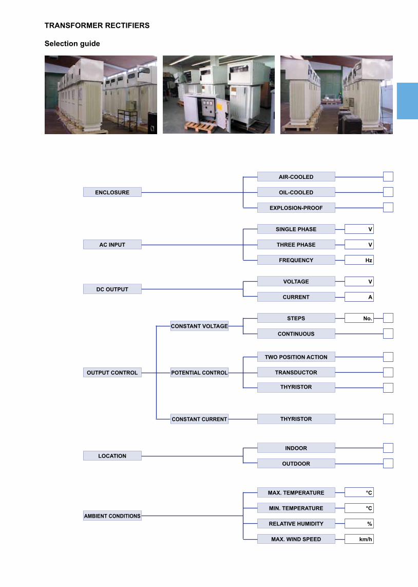
TRANSFORMER RECTIFIERS
Selection guide
AIR-COOLED
OIL-COOLEDENCLOSURE
SINGLE PHASE
THREE PHASE
FREQUENCY
AC INPUT
EXPLOSION-PROOF
V
V
Hz
VOLTAGE
CURRENT
V
ADC OUTPUT
STEPS
CONTINUOUS
No.CONSTANT VOLTAGE
TWO POSITION ACTION
TRANSDUCTOR
THYRISTOR
POTENTIAL CONTROLOUTPUT CONTROL
THYRISTORCONSTANT CURRENT
INDOOR
OUTDOORLOCATION
MAX. TEMPERATURE
MIN. TEMPERATURE
RELATIVE HUMIDITY
MAX. WIND SPEED
AMBIENT CONDITIONS
°C
°C
%
km/h

TRANSFORMER RECTIFIERS
Selection guide
DC AMMETER
POTENTIAL METER
WORKING HOUR METER
SYNCHRONISABLE
NON SYNCHRONISABLECURRENT INTERRUPTER
Zn > Cu/CuSO4
Ag/AgCl > Cu/CuSO4POTENTIAL CONVERTER
LIGHTNING ARRESTER
WITHSTAND H.V. UP TO 3 kV AC
AC VOLTMETER
AC AMMETER
DC VOLTMETER
FAILURE ALARM
POTENTIAL
DC OUTPUT
REMOTE MONITORING
CURRENT LIMITATION
BASE CURRENT SETTING
Other Requirements
MnO2 > Cu/CuSO4