Active ageing of the active elderly in Serbia - empirical approach
Upload
khangminh22Category
view
5download
0
Electronics 2021, 10, 1520. https://doi.org/10.3390/electronics10131520 www.mdpi.com/journal/electronics
Review
Hybrid Three-Phase Rectifiers with Active Power Factor
Correction: A Systematic Review
José Teixeira Gonçalves 1,*, Stanimir Valtchev 1, Rui Melicio 2,3, Alcides Gonçalves 1 and Frede Blaabjerg 4
1 Departamento de Engenharia Eletrotécnica e de Computadores, CTS/UNINOVA, FCT, Universidade
NOVA de Lisboa, FCT Campus Caparica, 2829-516 Monte Caparica, Portugal; [email protected] (S.V.);
[email protected] (A.G.) 2 Instituto de Engenharia Mecânica (IDMEC), Instituto Superior Técnico, Universidade de Lisboa, Av.
Rovisco Pais 1, 1049-001 Lisboa, Portugal 3 Instituto de Ciências da Terra (ICT), Universidade de Évora, Rua Romão Ramalho 59,
7002-554 Évora, Portugal; [email protected] 4 Department of Energy Technology, University of Aalborg, Pontoppidanstræde 111,
9220 Aalborg Øst, Denmark; [email protected]
* Correspondence: [email protected]
Abstract: The hybrid three-phase rectifiers (HTR) consist of parallel associations of two rectifiers
(rectifier 1 and rectifier 2), each one of them with a distinct operation, while the sum of their input
currents forms a sinusoidal or multilevel waveform. In general, rectifier 1 is a GRAETZ (full bridge)
(can be combined with a BOOST converter) and rectifier 2 is combined with a DC-DC converter. In
this HTR contest, this paper is intended to answer some important questions about those hybrid
rectifiers. To obtain the correct answers, the study is conducted as an analysis of a systematic
literature review. Thus, a search was carried out in the databases, mostly IEEE and IET, and 34
papers were selected as the best corresponding to the HTR theme. It is observed that the preferred
form of power distribution in unidirectional hybrid three-phase rectifiers (UHTR) is 55%��
(rectifier 1) and 45%�� (rectifier 2). For the bidirectional hybrid three-phase rectifiers (BHTR),
rectifier 1 preferably takes 90% of �� and 10% of �� is processed by rectifier 2. It is also observed
that the UHTR that employ the single-ended primary-inductor converter (SEPIC) or VIENNA
converter topologies in rectifier 2 can present sinusoidal input currents with low total harmonic
distortion (THD) and high Power Factor (PF), even successfully complying with the international
standards. The same can be said about the rectifier that employs a pulse-width (PWM) converter of
BOOST topology in rectifier 2. In short, the HTR are interesting because they allow using the
GRAETZ full bridge topology in rectifier 1, thus taking advantage of its characteristics, being
simple, robust, and reliable. At the same time, the advantages of rectifier 2, i.e., high PF and low
THD, are well used. In addition, this article also points out the future direction of research that is
still unexplored in the literature, thus giving opportunities for future innovation.
Keywords: hybrid three-phase rectifier (HTR); EV battery charging; unidirectional rectifier;
bidirectional rectifier; BOOST; SEPIC; VIENNA; delta-switch; star-switch; PWM BOOST; power
factor; systematic review
1. Introduction
The use of alternating current (AC) electricity as a standard in electrical networks
was practically established through the competition known as the “war of currents”,
where Nikola Tesla and George Westinghouse defended the use of AC, and their
opponent Thomas Edison advocated the use of direct current (DC) in the 19th century.
Nikola Tesla’s electric power in AC won the “war of currents” for several reasons, the
most notable being the possibility of generating large amounts of electric energy and
Citation: Gonçalves, J.T.; Valtchev,
S.; Melicio, R.; Gonçalves, A.;
Blaabjerg, F. Hybrid Three-Phase
Rectifiers with Active Power Factor
Correction: A Systematic Review.
Electronics 2021, 10, 1520.
https://doi.org/10.3390/
electronics10131520
Academic Editor: Carlos Andrés
García-Vázquez
Received: 25 May 2021
Accepted: 18 June 2021
Published: 23 June 2021
Publisher’s Note: MDPI stays
neutral with regard to jurisdictional
claims in published maps and
institutional affiliations.
Copyright: © 2021 by the authors.
Licensee MDPI, Basel, Switzerland.
This article is an open access article
distributed under the terms and
conditions of the Creative Commons
Attribution (CC BY) license
(http://creativecommons.org/licenses
/by/4.0/).

Electronics 2021, 10, 1520 2 of 31
allowing the transport of electric power over great distances at a financial cost more viable
and efficient than the DC system [1]. Nowadays, this AC power system has become the
standard. Since the electrical network is given in AC, and most charges use electrical
energy in DC, such as TVs, computers, radios, electric vehicles, etc., an AC–DC rectifier is
incorporated into the loads [2,3].
In principle, AC rectification systems in DC were only possible with
electromechanical converters. Electromechanical converters consist of an AC motor
coupled to the shaft of a DC generator. This has the disadvantage of being an expensive,
bulky, heavy, and noisy system. Subsequently, the studies and developments of mercury
converters emerged, which remained until the end of 1950, which were surpassed by the
invention of the semiconductor component [4]. Depending on technological development,
solid-state electronic devices appeared in Bell Telephone’s laboratories. However, it was
only in 1960 that the first diode rectifier capable of rectifying a current of 100 kA was
commercially launched. Afterwards, thyristor rectifiers also appeared with the capacity
to rectify currents of the order of 100 kA [2,4].
With the invention of these semiconductor elements, the development of technology
has made great strides. Currently, it is already possible to build rectifier plants that will
work with currents above 350 kA. Of course, these semiconductor elements are not ideal;
they have some disadvantages such as thermal losses. Thermal losses cause high heating
and can cause the device to burn, but this can be solved by using heat sinks with forced
cooling (cooling by deionized water or ventilated air), and water cooling is for high-power
converters [2–4].
Another concern concerns the disturbances injected into the electrical network, since
these switching elements (diodes, MOSFETs, IGBTs, etc.) are used in converters (rectifiers
and inverters) and active loads, which are activated by the frequency of the electrical
network (diode rectifiers) or through a control, thus giving rise to the injection of
harmonics into the electrical network. To mitigate the disturbances that converters or
loads can cause in the electrical network, standards have been imposed by energy
concessionaires as a measure to safeguard the quality of energy in the electrical network.
Examples of well-established and internationally known standards used on energy
quality are IEC61000-3-2 and IEC61000-3-4, and in relation to the total harmonic distortion
(THD) of the current injected into the electrical network, it used IEEE Std 519–2014. With
this, the challenge today is to develop a system of medium or high-power converters that
are even more efficient and reliable, as is the case with three-phase rectifiers [2–4].
Currently, there are several types of three-phase rectifiers with reduced harmonic
content connected in several loads, which can be classified into two large groups, the
bidirectional and unidirectional. In the case of unidirectional rectifiers, they use the diodes
as a switching device, being activated by the frequency of the electrical energy that is
applied, as is the case of the GRAETZ bridge rectifier. These rectifiers present the problem
of high total harmonic distortion (THD). Bidirectional rectifiers, on the other hand, use
switching devices (MOSFETs, IGBTs, etc.) activated by means of a control system [2,3].
These rectifiers can achieve good results such as low THD and high Power Factor (PF),
and they can even meet international standards. These rectifiers present the problem of
complexity (due to the control system) and economic viability when applied at high
powers.
Some power factor correction techniques have been developed to reduce the
harmonic content of some three-phase rectifiers. Figure 1 shows the classification of three-
phase rectifiers with reduced harmonic content. These three-phase rectifiers can show
improvements in THD and PF, and some rectifiers can meet the standards of established
international norms, as is the case of the hybrid three-phase rectifiers (HTR) that are part
of the scope of study in this paper.

Electronics 2021, 10, 1520 3 of 31
Figure 1. Classification of three-phase rectifiers with reduced harmonic content.
Scope and Objective of the Study
In Figure 1, a classification of three-phase rectifier systems for low and medium
power is illustrated [5]. The focus of this work is related to the HTR in line with the power
flow. These rectifiers (in line with the power flow) can be classified as unidirectional
hybrid three-phase rectifiers (UHTR) and bidirectional hybrid three-phase rectifiers
(BHTR), as shown in Figure 1 [5].
The HTR studied in this work can be analyzed as rectifiers with series or parallel
connection between two (usually rectifier 1 and rectifier 2) or more rectifiers. Rectifier 1 is
switched by the line, and in some cases, it can be connected in series with a DC converter
to control the output voltage; it must also be designed in such a way that it processes the
largest possible portion of the total energy delivered to the load. Rectifier 2, on the other
hand, can be auto switched (controlling the output voltage) or even switched over the line,
but connected without series with a DC converter to control the output voltage and carry
out the active power factor correction, processing the remaining portion of the total energy
delivered to the load. In addition, the rectifiers must process different current waveforms
in such a way that their union reaches the desired for the source (sinusoidal or multilevel)
and the load [2,6].
In this case, the Minnesota rectifiers, and the rectifiers in parallel to the energy flow
(rectifiers with active filters and hybrid filters) will not be studied in this paper, since their
principles of operation are different. These rectifiers work in conjunction with a stage that
is of the active filter type and is a device that allows the elimination of harmonics from
equipment operating with non-linear loads; however, it basically processes reactive
energy with no active power supply for the load [7].
In the case of the HTR studied in this paper, a great variety is found in the literature,
because they can be classified or composed of several types of rectifiers and converters,
such as the VIENNA rectifier, rectifier with BOOST converter, single-ended primary-
inductor converter (SEPIC), etc. Therefore, to improve the studies of HTR, this systematic
literature review paper has the following main objectives:
Briefly and systematically present the existing work in relation to HTR technology;
Identify gaps in the current state of the art of HTR, to suggest additional research;
Provide the basis for new HTR research activities;
Organize the HTR contents.
This paper is organized in such a way that the applied methodology is described in
Section 2 and the analyses are presented in Section 3, where the six main research
questions are answered. Next, the discussion is presented in Section 4, and finally, the
conclusions in Section 5 are presented.

Electronics 2021, 10, 1520 4 of 31
2. Methods
The main objective of this paper is to collect content, analyze, and systematically
summarize the types of three-phase hybrid rectifiers (HTR) with active power factor
correction that exist in the literature. In this context, this study is categorized as a
secondary study. The methodology used in this systematic review is based on the
methodology proposed in [8,9].
2.1. Research Questions (RQ)
The questions are designed to meet the objectives of this systematic review, which
are extremely important within the review of three-phase hybrid rectifiers and thus lead
this study to an appropriate and necessary line of thought. The relevant questions for this
review study are as follows:
1. RQ1: In what period were the HTR published?
2. RQ2: Who are the main actors in HTR?
3. RQ3: What types of HTR are there in the literature?
4. RQ4: What types of control are most used in HTR?
5. RQ5: What types of HTR comply with international standards regarding the quality
of energy in the electrical networks?
6. RQ6: What type of loads are HTR applied to?
2.2. Search
The systematic review was based on the search for scientific documents that
demonstrate studies on HTR. The period of research of the documents had as reference
(starting) the first HTR proposed in the literature in 1999 [10], which means that the HTR
from 1999 to 2020 existing in the literature are studied. The year 2021 was not considered
because, to date, there have been no publications on HTR. For searches of scientific
documents, the following two databases were used: IEEE Xplore and the IET Digital
Library.
Search Terms
To obtain most of the relevant work in the literature on hybrid three-phase rectifiers
with active correction of the power factor, some search terms were developed. These
search terms were designed to include most studies of unidirectional and bidirectional
three-phase hybrid rectifiers, as well as multilevel and multipulse hybrid three-phase
rectifiers, so it was possible to obtain the correct search terms and combine them to use in
abstracts and titles of studies in the databases. Table 1 shows the strings executed in the
two selected databases. With the execution of these strings, 153 articles were generated
and are distributed in the respective databases according to Table 2.
Table 1. String used in databases.
Database Search Terms
IEEE Xplore
(“All Metadata”: “Hybrid Three-Phase”) OR (“All Metadata”:
“Hybrid Rectifiers”) OR (“All Metadata”: “Hybrid Rectifier”) OR
(“Document Title”: “Hybrid Unidirectional”) OR (“Document
Title”: “Three-Phase Unidirectional”) OR (“Document Title”:
“Hybrid Multilevel Power”) OR (“Document Title”: “Hybrid
Multipulse “)
IET Digital Library “Hybrid Rectifiers” OR “Hybrid VIENNA rectifier

Electronics 2021, 10, 1520 5 of 31
Table 2. Results of search queries in the databases.
Query Results from Query Date
IEEE Xplore 131 28 April 2021
IET Digital Library 22 29 April 2021
2.3. Criteria
To select the studies considered suitable for this review, within the set of studies
resulting from the consultations (153 articles), exclusion and inclusion criteria were thus
elaborated, as mentioned in Section 2.3.1 and 2.3.2, consecutively. After these criteria were
executed, 34 papers were selected, which in turn are applied to the data extraction phase.
2.3.1. Exclusion Criteria
Studies not related to HTR.
Studies related to single-phase hybrid rectifiers.
Studies related to Minnesota rectifiers.
Studies related to three-phase rectifiers with active filters and hybrid filters.
Studies related to three-phase rectifiers without active correction of the power factor.
2.3.2. Inclusion Criteria
Studies related to HTR.
Studies related to the application of HTR.
Studies that describe the principle of operation of the HTR.
Studies that describe the control methodology applied to the HTR.
Studies that describe the design or dimensioning of HTR.
Studies that describe the power distribution in the HTR.
2.4. Data Extraction Method
The information extracted from the literature review to answer the RQs was
submitted to an analysis procedure organized as follows:
1. The number of HTR published per year and their publication channels (addressing
RQ1 and analyzed in Section 3.1).
2. Name of the authors and their affiliations as well as the paper number (addressing
RQ2 and analyzed in Section 3.1).
3. Describe the operation of the HTR (addressing RQ3 and analyzed in Section 3.2).
4. Describe the name of the HTR (addressing RQ3 and analyzed in Section 3.2).
5. Present the design of the HTR (addressing RQ3 and analyzed in Section 3.2.2).
6. Describe the control strategy applied (addressing RQ4 and analyzed in Section 3.3).
7. Mention the type of integrated circuit applied in the control (addressing RQ4 and
analyzed in Section 3.3).
8. Mention the PF and THD obtained in the types of HTR, as well as the power
distribution (addressing RQ5 and analyzed in Section 3.4).
9. Describe the type of application of the HTR (addressing RQ6 and analyzed in Section
3.5).
3. Analysis
This section analyzes and describes the findings related to the literature review of the
34 selected articles to answer the six questions presented in Section 2.1, which are
organized in sections, as also indicated in Section 2.4.
A summary of how the 34 papers were selected for data extraction is presented in a
flow diagram of the systematic review, the so called “Preferred Reporting Items for
Systematic Reviews and Meta-Analyses” known shortly as PRISMA. The diagram is
illustrated in Figure 2. It shows the three major phases of the process, with the

Electronics 2021, 10, 1520 6 of 31
identification of papers in the selected databases, the readability of the papers, and lastly
the selected papers.
Figure 2. Flow diagram of the systematic review (PRISMA).
3.1. HTR Paper Publications
The number of selected articles published between 1999 and 2020 are presented and
distributed annually in Figure 3. In general, few articles were published annually, with
the years with the highest publication being 2011, 2013, and 2018, followed by the years
from 2019 and from 2005 to 2007.
Next, the paper publication channels of journals and conferences are also presented
in Table 3. Only 10 papers were published in journals; that is, 29.41% of all papers were
published in journals, with the remaining publications from conferences. Only two
conferences have published more than one paper, while the others have published only
one paper.
It is important to determine the main authors of the three-phase hybrid rectifiers and
thus to know which country leads this technology. For this, Table 4 shows the names of
the authors and their affiliations with at least two publications. We can notice that the
country leading this three-phase hybrid rectifier system is Brazil. Another important point
that reinforces this analysis is that among the 10 articles published in journals, five of them
were published by Brazilian actors.

Electronics 2021, 10, 1520 7 of 31
Figure 3. Number of papers published annually.
Table 3. Publication channels.
Channels Means Reference Nº %
IEEE Transactions on Industrial Electronics Journal [11–13] 3 8.82
IEEE Transactions on Power Electronics Journal [6,14] 2 5.9
IEEE Transactions on Industry Applications Journal [15,16] 2 5.9
IET Power Electronics Journal [17,18] 2 5.9
IEEE Transactions on Industrial Informatics Journal [19] 1 2.94
IEEE Power Electronics Specialists
Conference (now is ECCE) Conference [20–23] 4 11.76
IEEE Applied Power Electronics
Conference and Exposition (APEC) Conference [24–26] 3 8.82
1st Global Power, Energy and Communication
Conference (GPECOM) Conference [2] 1 2.94
Conference Record of the 1999 IEEE
Industry Applications Conference Conference [10] 1 2.94
IEEE International Symposium on
Industrial Electronics Conference [27] 1 2.94
7th International Conference on Power
Electronics Conference [28] 1 2.94
IEEE Industry Applications Society
Annual Meeting Conference [29] 1 2.94
Twenty-Seventh Annual IEEE Applied
Power Electronics Conference and
Exposition (APEC)
Conference [30] 1 2.94
International Conference on Electrical
Machines and Systems (ICEMS) Conference [31] 1 2.94
19th European Conference on Power
Electronics and Applications Conference [32] 1 2.94
IEEE International Conference of Safety
Produce Informatization (IICSPI) Conference [33] 1 2.94
IEEE International Power Electronics and
Application Conference and Exposition Conference [34] 1 2.94
IEEE 9th International Power Electronics
and Motion Control Conference Conference [35] 1 2.94
31st Annual Conference of IEEE Industrial
Electronics Society (IECON) Conference [36] 1 2.94

Electronics 2021, 10, 1520 8 of 31
International Conference on Nanoscience,
Engineering and Technology (ICONSET) Conference [37] 1 2.94
XI Brazilian Power Electronics Conference Conference [38] 1 2.94
20th European Conference on Power
Electronics and Applications, EPE Conference [39] 1 2.94
37th Annual Conference of the IEEE
Industrial Electronics Society (IECON) Conference [40] 1 2.94
The Journal of Engineering Conference [41] 1 2.94
Table 4. Authors on HTR and the number of papers published.
Name of Authors Affliction (University, Country) Nº Papers
Luiz Carlos Gomes de Freitas et al. Federal University of Uberlandia
(UFU); Brazil 6
Damarco Vieira Costa et al. Federal University of Uberlandia
(UFU); Brazil 4
Ricardo Luiz Alves et al. Federal University of Santa Catarina
(UFSC); Brazil 3
Jurandir de O. Soares et al. São Paulo State University (UNESP);
Brazil 2
Wei-Zhang Song et al. Xi’an University of Technology;
China 2
3.2. Principle of Operation of HTR
To understand the principle of operation of the HTR, it is essential to analyze the
operation through the current path and the power flow distributed between the rectifiers,
since the current will pass through the two rectifiers. The explanation the principle of
operation is based on the figures represented in subsection 3.2.2., so it can be said that the
input currents (��, ��, ��) are distributed over two paths, for rectifier 1 (���, ���, ���) and for
rectifier 2 (���, ���, ��� ), and then after being rectified and processed by the respective
converters, the two output currents (��� ��� ���, respectively) in DC are added in the DC
bus, thus obtaining the current of output (�� ) of the HTR, since the two rectifiers are
connected in parallel [2,6,13,16–18,20,23,25,26,28,32,34,36,40]. In a specific way, we will
analyze the operation by part, being for the structure of rectifier 1 and then for rectifier 2.
Rectifier 1.
The structure of rectifier 1 can be formed in two modes; the first is formed only by a
three-phase bridge with six pulses (GRAETZ bridge), while the second is formed by the
three-phase bridge with six pulses (GRAETZ bridge) associated in series by a converter
BOOST. In the first mode, the output voltage is not controlled, and it is not possible to
impose the current waveform; in this case, the value of the output voltage depends on the
value of the input voltage and the load consumption. In this mode, we can also implement
a filter inductive at the input of each phase of the rectifier or implement the inductive filter
at the output of the rectifier. These current waveforms, such as the rectangular one, are
due to the activation of the diodes, which activate in a switching interval of 30° and 150°
(considering only a semi-cycle), thus conducting the current in this interval
[20,23,25,28,31,36,38]. In the second mode, the GRAETZ bridge rectifier is connected in
series with a BOOST converter to control the output voltage and reduce the ripples of the
rectangular current shape. With an appropriate BOOST inductance value and with a
suitable control loop (such as PWM) that provides the appropriate command to the power
switch, it is possible to obtain practically negligible ripples on the inductor and a control
of the average value of the applied output voltage to the load [2,16,26,27]. In this case, the
control is done by two loops, the voltage loop, and the current loop, as shown in Figure 4.

Electronics 2021, 10, 1520 9 of 31
The voltage loop aims to keep the output voltage constant under load variations, and
therefore, it receives an output voltage signal (through a voltage sensor) and compares it
with a reference voltage (����) of the same value in order to produce an error (��) that will
be used to change the amplitude of the current signal so that the PWM block can generate
the proper pulse widths for controlling the output voltage. In this case, the current loop
only has the purpose of imposing the current amplitude (by means of a reference signal
of constant value), to allow a certain desired current value (thus allowing a better power
distribution in the HTR) and rectangular in shape. Note that some hybrid structures (not
all) may have the GRAETZ bridge rectifier 1 and BOOST converter with some minor
modifications to allow a correct operation; the modification consists of dividing the
BOOST diode and the BOOST inductor, as shown in Figure 4 [2,3,6,21,29,34].
This structure has very interesting characteristics, being robust, simple, reliable, low
volume, low financial cost, and widely applied in low power devices; however, it cannot
be used for high power levels, because its input currents have a total harmonic distortion
current (THDi) of approximately 30% and a PF of 95%, which does not meet the IEC 61000-
3-2/61000-3-4 standards [22,27,28]. Given the qualities of this rectifier (robust, simple,
reliable, low volume, low financial cost), it is interesting to combine intelligently (hybrid)
with another rectifier to take advantage of the qualities of each one.
Figure 4. GRAETZ bridge rectifier with BOOST converter and respective control system.
Rectifier 2
Since it is a three-phase hybrid rectifier and knowing how rectifier 1 works, rectifier
2 must function intelligently, thus conducting the electric current (considering the analysis
in a semi-cycle) in periods when rectifier 1 does not conduct the current, and rectifier 2
must allow the current to pass to a certain level conditioned to the level driven by rectifier
1. This way, the current is conducted in every semi-cycle in an intelligent way, taking
advantage of the benefits of each rectifier. Rectifier 2 must be able to control (impose) the
current waveform. It must also be able to control the average value of the output voltage
applied to the load, since the value of the output voltage must be the same for the two
rectifiers [2,3,6,21,29,34].
Note that theoretically, any three-phase rectifier with PWM control that allows
changing the current waveform can be used as rectifier 2 within the structure of an HTR
[2,21].
In this way, unidirectional rectifiers and bidirectional rectifiers can be used. In the
case of a unidirectional rectifier, the modular three-phase rectifier with BOOST converter
and PFC can be used [2,20,25,36]; the three-phase modular rectifier with SEPIC converter

Electronics 2021, 10, 1520 10 of 31
and PFC [16,23,28,29,38]; and the three-phase VIENNA rectifier with PFC [6,18,27], as well
as their versions known as the three-phase Delta-switch rectifier with PFC [13,32,40] and
the three-phase rectifier Star-switch with PFC [17,41]. In the case of a bidirectional
rectifier, the three-phase PWM rectifier of the BOOST type with PFC can be used
[26,31,34].
These rectifier structures, by permitting the output voltage regulation and power
factor correction, show a low THD and high PF. Thus, they are capable of complying with
the norm IEC 61000-3-2/61000-3-4, which is compulsory for many power electronic
converters aimed at a high quality of electric energy. Therefore, it is of great interest to
combine the rectifiers and obtain advantages of both rectifiers.
Unidirectional three-phase modular rectifier with BOOST converter: It is a structure
composed of three single-phase blocks, each block being composed of a single-phase
rectifier and a BOOST converter with active power factor correction. The operation of a
block is similar with the other blocks, so it is enough to explain just one block. Some
studies present these rectifiers with an isolation transformer at the entrance of each phase
(or block) to avoid the current interactions between the phases, as illustrated in Figure 5
[12,14,20,25,36]. Another study presents this structure without the isolation transformer,
but it replaced the BOOST inductor with a coupled inductor to mitigate current
interactions, as shown in Figure 6 [2]. The control with PFC is given by two loops, the
voltage loop, and the current loop (three current loops, one for each phase), as can be seen
in Figure 5 and Figure 6. The voltage loop controls the output voltage by means of a signal
of the output voltage that will be compared with a reference voltage (����), thus generating
a tenon error (��) being sent to the voltage compensator (��(�)). Then, the obtained signal
is distributed over the current of each phase, this being multiplied by the signal of the
reference voltage of the sinusoid ( ����.� , ����.�, ����.� ) (synchronized with the mains
voltage). Then, an adder receives this signal and the current signal from the inductor
(obtained by means of a current sensor), and the generated signal is applied to their
respective current compensators (��(�)) and to the PWM modulator that will generate the
gate signals for the corresponding power switch (S) [2,12,20].
Figure 5. Modular three-phase rectifier with BOOST converter and isolation transformer.

Electronics 2021, 10, 1520 11 of 31
Figure 6. Modular three-phase rectifier with BOOST converter and coupled inductor.
Unidirectional three-phase modular rectifier with SEPIC converter: It is also a
structure composed of three single-phase blocks, each block being composed of a single-
phase rectifier and a SEPIC converter with active power factor correction. This structure
is interesting because it allows the connection of three modules to work as a three-phase
rectifier without any current interaction between the phases, thanks to the series capacitor
that guarantees, under any operating conditions, the decrease of the current that flows
through the input inductor (thus, the imposition of the input current does not depend
strongly on the level of the output voltage) [12,17,20,22]. There are two forms of
constitution of this rectifier, which are based on the exposure of the SEPIC inductor. The
first form is based on the conventional SEPIC converter but with a small modification of
dividing the SEPIC inductor and capacitor by two (one on the positive and one on the
negative) [12,22], as shown in Figure 7. The second way is to implement the SEPIC
inductor at the input of each rectifier phase [16,19,29,30,38]. Control is also provided by
two loops: the voltage loop and the current loop. The process of the voltage loop and the
reference signal that goes to the current compensator (��(�)) is basically the same as that
already described in the modular rectifier with a BOOST converter. However, in this
system, each current compensator (��(�)) with the PWM modulator generates a suitable
signal for the power switch of the SEPIC converter.
Figure 7. Modular three-phase rectifier with SEPIC converter.
Unidirectional VIENNA rectifier: The two-level VIENNA rectifier is widely used, as
shown in Figure 8. This structure works with the three phases without the need for
neutral, and the inductor is implemented at the input of each phase of the rectifier, with

Electronics 2021, 10, 1520 12 of 31
each phase being controlled by a toggle switch. Control is also provided by two loops: the
voltage loop and the current loop (one current loop for each phase). The process of the
voltage loop and the reference signal that goes to the current compensator (��(�)) for each
phase is basically the same as that already described in the modular rectifier with the
BOOST converter, as can be seen in Figure 8. However, in this system, each compensator
of current (��(�)) with the PWM modulator generates a gate signal suitable for the power
switch (S) of the respective rectifier. It is important to note that when applying this classic
control to this topology, there is a need to synchronize the carriers (“sawtooth” waves) of
the PWM modulator in each phase. In this way, the control causes the cyclic ratio for the
phase with the highest current (and the highest current reference) to present the highest
cyclic ratio, respecting this condition for the controllability of the currents [6,18,27].
However, other versions of this two-level VIENNA rectifier, such as the Delta-switch
rectifier and the Star-switch rectifier, were also studied and analyzed in more detail in
Section 3.2.1.
Figure 8. VIENNA rectifier with PFC and respective control system.
BOOST-type PWM bidirectional three-phase rectifier: It is widely used when good
sinusoidal currents are desired. This structure also has an inductor in each phase and is
controlled by six power switches, as shown in Figure 9. Control is also given by two loops:
the voltage loop and the current loop. The voltage loop and reference signal process that
goes to the current compensator (��(�) ) is basically the same as that described in the
VIENNA rectifier. In this case, each current compensator (��(�)) with the PWM modulator
generates two port signals suitable for the rectifier system [26,34].

Electronics 2021, 10, 1520 13 of 31
Figure 9. BOOST-type PWM rectifier with PFC and respective control system.
Power Distribution
The distribution of power between the rectifiers is an important factor, as it
determines the proper functioning of the three-phase hybrid rectifier and determines the
quality of the input current that is to be obtained. Since the value of the output voltage is
the same for the rectifiers, then the current distribution will determine the power
distribution. At first, it is known that the input current is divided into two paths (two
rectifiers connected in parallel), so it is only necessary to determine the right amount of
current for each rectifier, thus determining the right power distribution between the
rectifiers [2]. Power distribution is possible in two ways, depending on the structure of
the HTR. In the first mode, the UHTR structure shown in Figure 10 is used, and the second
mode is used in the configuration shown in Figure 11 [2,6,18,25,27].
Figure 10. Representation of the first mode for power distribution in the HTR using the K gain.
Electronics 2021, 10, 1520 14 of 31
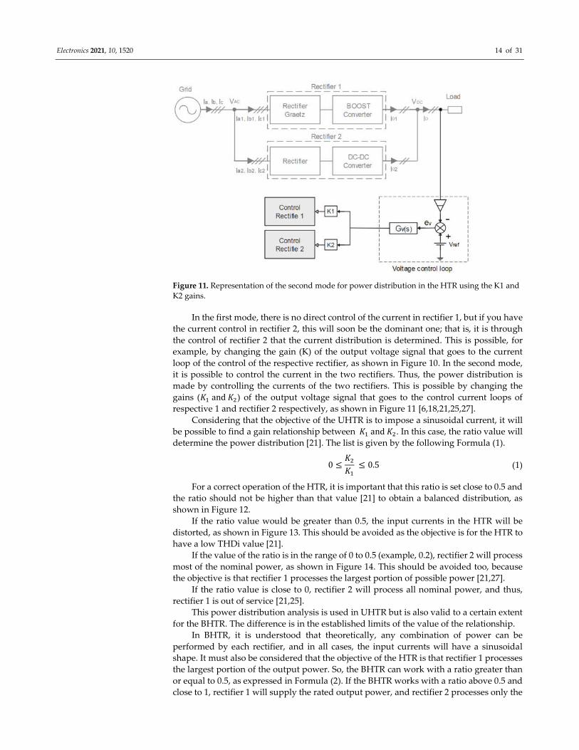
Figure 11. Representation of the second mode for power distribution in the HTR using the K1 and
K2 gains.
In the first mode, there is no direct control of the current in rectifier 1, but if you have
the current control in rectifier 2, this will soon be the dominant one; that is, it is through
the control of rectifier 2 that the current distribution is determined. This is possible, for
example, by changing the gain (K) of the output voltage signal that goes to the current
loop of the control of the respective rectifier, as shown in Figure 10. In the second mode,
it is possible to control the current in the two rectifiers. Thus, the power distribution is
made by controlling the currents of the two rectifiers. This is possible by changing the
gains (�� and ��) of the output voltage signal that goes to the control current loops of
respective 1 and rectifier 2 respectively, as shown in Figure 11 [6,18,21,25,27].
Considering that the objective of the UHTR is to impose a sinusoidal current, it will
be possible to find a gain relationship between �� and ��. In this case, the ratio value will
determine the power distribution [21]. The list is given by the following Formula (1).
0 ≤��
�� ≤ 0.5 (1)
For a correct operation of the HTR, it is important that this ratio is set close to 0.5 and
the ratio should not be higher than that value [21] to obtain a balanced distribution, as
shown in Figure 12.
If the ratio value would be greater than 0.5, the input currents in the HTR will be
distorted, as shown in Figure 13. This should be avoided as the objective is for the HTR to
have a low THDi value [21].
If the value of the ratio is in the range of 0 to 0.5 (example, 0.2), rectifier 2 will process
most of the nominal power, as shown in Figure 14. This should be avoided too, because
the objective is that rectifier 1 processes the largest portion of possible power [21,27].
If the ratio value is close to 0, rectifier 2 will process all nominal power, and thus,
rectifier 1 is out of service [21,25].
This power distribution analysis is used in UHTR but is also valid to a certain extent
for the BHTR. The difference is in the established limits of the value of the relationship.
In BHTR, it is understood that theoretically, any combination of power can be
performed by each rectifier, and in all cases, the input currents will have a sinusoidal
shape. It must also be considered that the objective of the HTR is that rectifier 1 processes
the largest portion of the output power. So, the BHTR can work with a ratio greater than
or equal to 0.5, as expressed in Formula (2). If the BHTR works with a ratio above 0.5 and
close to 1, rectifier 1 will supply the rated output power, and rectifier 2 processes only the

Electronics 2021, 10, 1520 15 of 31
energy necessary to reach a sinusoidal current with high PF and low THD, as shown in
Figure 15 [26]. This is also an interesting operating mode for the correct functioning of the
BHTR.
0.5 ≤��
��
≤ 1 (2)
(a)
+
(b)
=
(c)
Figure 12. Current waveforms in phase a of the HTR. (a) Input current in rectifier 1. (b) Input current in rectifier 2. (c)
Input current (sinusoidal) in the HTR.
(a)
+
(b)
=
(c)
Figure 13. Current waveforms in phase a of the HTR. (a) Input current in rectifier 1. (b) Input current in rectifier 2. (c)
Input current (distorted sinusoidal) in the HTR.
(a)
+
(b)
=
(c)
Figure 14. Current waveforms in phase a of the HTR. (a) Input current in rectifier 1. (b) Input current in rectifier 2. (c)
Input current (sinusoidal) in the HTR.
(a)
+
(b)
=
(c)
Figure 15. Current waveforms in phase a of the HTR. (a) Input current at rectifier 1. (b) Input current at rectifier 2. (c) Input
current (sinusoidal) at BHTR.
3.2.1. Classification of HTR
As mentioned in the operation of the HTR, the type of HTR depends on the type of
converter applied to rectifier 2. Thus, we can have a three-phase hybrid rectifier using a
rectifier 2 BOOST, SEPIC, VIENNA, Delta-switch, Star-switch, and PWM BOOST.
Due to the organization of the rectifiers, it is important to investigate and analyze the
names given to the different types of existing three-phase hybrid rectifiers. Therefore, in
Table 5, the names that were assigned in the HTR found in the literature (paper) are

Electronics 2021, 10, 1520 16 of 31
shown. We can see that in many papers, they practically do not assign a specific name to
the studied HTR, they only describe it as HTR, while other publications (papers) assign a
specific name to the studied rectifier. On the other hand, if we analyze, we will see that
the names are assigned individually (by paper), and therefore, when we compare these
names, we will notice that they do not follow a pattern, which makes the studies of HTR
less organized. To improve the organization of the HTR, we propose in Table 5 the
appropriate name for each rectifier, as mentioned in the papers. The proposed names are
given following a logical form of the constitution of the rectifier so that they can follow a
pattern.
Table 5. HTR classification proposed.
HTR Name in the Paper Reference HTR Name Proposal Acronym
Hybrid three-phase rectifier with
BOOST converter without isolation
transformer
[2]
Unidirectional hybrid three-phase
rectifier with BOOST converter on
rectifier 1 and BOOST converter on
rectifier 2
UHTR-
BR1//BR2
PFC Based Hybrid Multipulse Power
Rectifier (PFC-HMPR) [20,25,36]
Unidirectional three-phase hybrid
rectifier with rectifier 1 and BOOST
converter on rectifier 2 with
transformer
UHTR-R1//BR2
- [16,29]
Unidirectional hybrid three-phase
rectifier with BOOST converters on
rectifier 1 and SEPIC converter on
rectifier 2
UHTR-
BR1//SR2
Power factor correction non-isolated
hybrid power rectifier (PFC-HPR)
[12,14,19,22–
24,28,30,38,39]
Unidirectional hybrid three-phase
rectifier with rectifier 1 and SEPIC
converter on rectifier 2
UHTR-R1//SR2
Unidirectional hybrid three-phase
voltage source rectifier (UHTPVSR) [6,13,18,21,27,33]
Unidirectional hybrid three-phase
rectifier with BOOST converters on
rectifier 1 and VIENNA converter on
rectifier 2
UHTR-
BR1//VR2
Hybrid three-phase rectifiers with
single-switch three phase BOOST
rectifier and the DELTA-switch rectifier
[13,32,40]
Unidirectional hybrid three-phase
rectifier with BOOST converters on
rectifier 1 and delta-switch converter
on rectifier 2
UHTR-
BR1//DR2
- [13,17,41]
Unidirectional hybrid three-phase
rectifier with BOOST converter on
rectifier 1 and Star-switch converter on
rectifier 2
UHTR-
BR1//StR2
Unidirectional hybrid three-phase
voltage source rectifier (UHTPVSR) [26,34]
Bidirectional hybrid three-phase
rectifier with BOOST converter on
rectifier 1 and PWM BOOST converter
on rectifier 2
BHTR-
BR1//BR2
- [26,31]
Bidirectional hybrid three-phase
rectifier with rectifier 1 and PWM
BOOST converter on rectifier 2 with
transformer
BHTR-R1//BR2
3.2.2. HTR Design
The HTR using the BOOST converter on rectifier 2 are referred to as UHTR-BR1//BR2
and UHTR-R1//BR2, as proposed in Table 5.

Electronics 2021, 10, 1520 17 of 31
UHTR-BR1//BR2 is represented in Figure 16 and was proposed in 2019 [2]. It consists
of rectifier 1 (GRAETZ bridge rectifier associated with a BOOST converter) associated in
parallel to rectifier 2 (modular three-phase rectifier with BOOST converter). The BOOST
converters have undergone a change to avoid interactions between the three modular
rectifiers that make up rectifier 2. The change is made by exchanging the BOOST converter
inductor for a coupled inductor, and a diode is implemented in the inverse of the current
interaction, thus forcing the current to travel in the normal direction [2].
Figure 16. Configuration of the electrical circuit of the UHTR-BR1//BR2.
The UHTR-R1//BR2 is shown in Figure 17 and proposed for the first time in 2005. It
consists of rectifier 1 (GRAETZ bridge rectifier with inductive filter) associated in parallel
to rectifier 2 (modular three-phase rectifier with BOOST converter). Each rectifier module
2 has an isolation transformer to avoid current interactions between the rectifiers. This
rectifier can impose 12-multilevel input currents [20,36], as shown in Figure 18 and
sinusoidal currents [25].
Figure 17. Configuration of the electrical circuit of the UHTR-R1//BR2.
Electronics 2021, 10, 1520 18 of 31
(a)
+
(b)
=
(c)
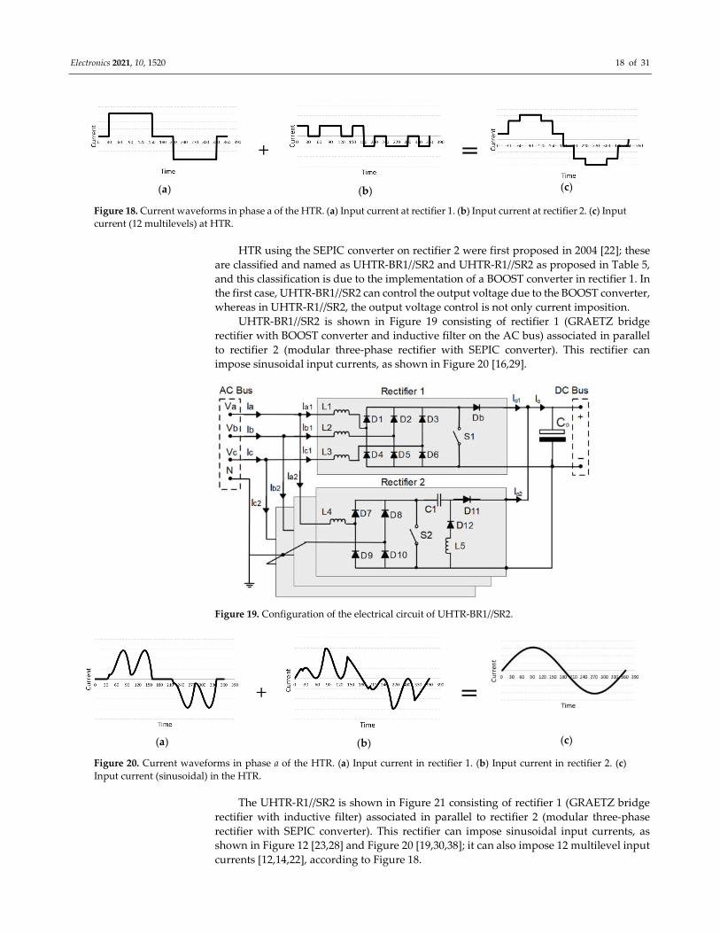
Figure 18. Current waveforms in phase a of the HTR. (a) Input current at rectifier 1. (b) Input current at rectifier 2. (c) Input
current (12 multilevels) at HTR.
HTR using the SEPIC converter on rectifier 2 were first proposed in 2004 [22]; these
are classified and named as UHTR-BR1//SR2 and UHTR-R1//SR2 as proposed in Table 5,
and this classification is due to the implementation of a BOOST converter in rectifier 1. In
the first case, UHTR-BR1//SR2 can control the output voltage due to the BOOST converter,
whereas in UHTR-R1//SR2, the output voltage control is not only current imposition.
UHTR-BR1//SR2 is shown in Figure 19 consisting of rectifier 1 (GRAETZ bridge
rectifier with BOOST converter and inductive filter on the AC bus) associated in parallel
to rectifier 2 (modular three-phase rectifier with SEPIC converter). This rectifier can
impose sinusoidal input currents, as shown in Figure 20 [16,29].
Figure 19. Configuration of the electrical circuit of UHTR-BR1//SR2.
(a)
+
(b)
=
(c)
Figure 20. Current waveforms in phase a of the HTR. (a) Input current in rectifier 1. (b) Input current in rectifier 2. (c)
Input current (sinusoidal) in the HTR.
The UHTR-R1//SR2 is shown in Figure 21 consisting of rectifier 1 (GRAETZ bridge
rectifier with inductive filter) associated in parallel to rectifier 2 (modular three-phase
rectifier with SEPIC converter). This rectifier can impose sinusoidal input currents, as
shown in Figure 12 [23,28] and Figure 20 [19,30,38]; it can also impose 12 multilevel input
currents [12,14,22], according to Figure 18.

Electronics 2021, 10, 1520 19 of 31
Figure 21. Configuration of the electrical circuit of UHTR-R1//SR2.
HTR using the two-level VIENNA rectifier on rectifier 2 were proposed in [21,27] and
developed in [6,18]. The rectifier proposed in Table 5 as UHTR-BR1//VR2 is also made up
of two rectifiers, as shown in Figure 22: rectifier 1 (three-phase GRAETZ bridge rectifier
associated with a BOOST converter, to control the output voltage) in parallel with the two-
level VIENNA rectifier. It can control the output voltage to keep it constant and impose
sinusoidal input currents, combining the different forms of current imposed on rectifier 1
and rectifier 2, as shown in Figure 12.
Figure 22. Configuration of the electrical circuit of UHTR-BR1//VR2.
There are other varieties of VIENNA three-phase rectifiers, but the structure of the
two-level VIENNA rectifier is the most used to compose an HTR. However, other
VIENNA rectifier structures are found in the literature, and they are also used as HTR
rectifier 2. These structures are known as the Delta-switch three-phase rectifier and the
Star-switch three-phase rectifier.
The Delta-switch rectifier has this name because it has six power switches connected
in a delta configuration, together with a three-phase six-diode rectifier. This Delta-switch
rectifier is connected in parallel with a GRAETZ bridge rectifier with a BOOST converter
proposed in [13,32,40] and proposed in Table 5 as UHTR-BR1//DR2, as represented in
Figure 23. The Star-switch rectifier consists of a three-phase bridge with six diodes and

Electronics 2021, 10, 1520 20 of 31
three power switches connecting the input phases to the neutral point of the DC bus. This
Star-switch rectifier was also connected in parallel with a GRAETZ bridge rectifier with
BOOST converter, as proposed in [14,17,41] and proposed in Table 5 as UHTR-BR1//StR2,
as represented in Figure 24.
Both the UHTR-BR1//DR2 and the UHTR-BR1//StR2 can control the output voltage
and impose sinusoidal input currents; this sinusoid is the combination of the rectifier 1
input current waveforms and rectifier 2, as shown in Figure 12.
Figure 23. Configuration of the electrical circuit of UHTR-BR1//DR2.
Figure 24. Configuration of the electrical circuit of the UHTR-BR1//StR2.
In the case of BHTR, only one possible structure was found in the literature [26],
which is composed of two rectifiers, as shown in Figure 25. Rectifier 1 (three-phase
GRAETZ bridge rectifier associated with a single switch BOOST converter) in parallel
with the PWM BOOST-type rectifier composed of six power switches. This rectifier
maintains the output voltage in a controlled manner and can impose sinusoidal input
currents. The imposed sinusoidal current comes from the combination of the different
forms of current imposed on rectifier 1 and rectifier 2, as shown in Figure 12 and Figure
15; it is proposed in Table 5 as BHTR-BR1//BR2.

Electronics 2021, 10, 1520 21 of 31
Figure 25. Configuration of the electrical circuit of BHTR-BR1//BR2.
Another structure named in Table 5 as BHTR-R1//BR2 and represented in Figure 26
comes from BHTR-BR1//BR2; its design was proposed in [26] and later developed in [31].
It differs from BHTR-BR1//BR2, because it does not have the ability to control the output
voltage, so the level of the output voltage is conditioned by the input voltage and the load
submitted. In this case, rectifier 1 consists only of a GRAETZ bridge and an inductive filter,
whereas in rectifier 2, a three-phase step-down autotransformer is implemented to
balance the voltages and allow the parallel connection between rectifiers 1 and rectifiers
2.
Figure 26. Configuration of the BHTR-R1//BR2 electrical circuit.
3.3. Control Strategy Applied
The control strategies analyzed are based on obtaining the signals that are sent to the
current and voltage control loop. Voltage and current control loops consist of integrated
circuits (analog) or digital signal processor circuits (digital). The working principle of
controlling voltage and current loops has already been described in Section 3.2 for the
converters BOOST, SEPIC, VIENNA and PWM BOOST. Therefore, the operation of the
integrated circuits of the analog control and the programming or digital signal processor

Electronics 2021, 10, 1520 22 of 31
of the digital control will not be further investigated since this content is not part of the
scope of this work.
Through the control strategy applied to the HTR, it can produce sinusoidal or
multilevel input currents [2,20,21], as shown in Table 6. In the same Table 6, we can also
notice that it is more common to develop HTR with sinusoidal input current.
Table 6. HTR type of control applied in HTR.
HTR Reference Control Circuit Employed Current
UHTR-BR1//BR2 [2] Analog Blocks Circuit Sinusoid
UHTR-R1//BR2
[20] Digital - Multilevel
[25] Digital Microcontroller Sinusoid
[36] Analog IC, Analog Ports Multilevel
UHTR-BR1//SR2 [16] Digital DSP, TMS320F28335 Sinusoid
[29] Digital DSP TMS320F2812 Sinusoid
UHTR-R1//SR2
[23] Digital FPGA, VHDL Sinusoid
[28] Digital FPGA, VHDL Sinusoid
[38] Digital DSP, TMS320F28335 Sinusoid
[19] Digital DSP, TMS320F28335 Sinusoid
[22] Analog Blocks Circuit Multilevel
[14] Analog - Multilevel
[12] Analog IC, Analog Ports Multilevel
[30] Digital DSP, TMS320F28335 Sinusoid
UHTR-BR1//VR2
[21] Analog Blocks Circuit Sinusoid
[6] Analog UC3854B Sinusoid
[18] Digital - Sinusoid
UHTR-BR1//DR2 [13] Digital DSP Sinusoid
[32] Digital DSP, TMS320F28335 Sinusoid
UHTR-BR1//StR2 [17] Digital DSP, TMS320F2812 Sinusoid
BHTR-BR1//BR2 [26] Analog Blocks Circuit Sinusoid
[34] Digital Mathematics Sinusoid
BHTR-R1//BR2 [31] Analog Blocks Circuit Sinusoid
For the sine wave, it is necessary that each HTR rectifier produces a different
waveform, in such a way that when adding the two waveforms, a sinusoidal current form
is obtained. For these forms of currents to be produced, an adequate control strategy is
necessary. According to the literature search, the most common HTR control strategy to
produce sinusoidal currents is shown in Figure 27. For the control system, current and
voltage input signals are necessary for both rectifier 1 and rectifier 2. Signal distributions
are made in the current loop and the voltage loop of rectifier 1 and rectifier 2 [2,21,26,27].
These are distributed as follows:
For the current loop of rectifier 1, the current signal of the BOOST inductor 1 (���) is
applied.
For the rectifier current loop 2, the input current signals, ��, ��, �� and the reference
voltage signals ��, ��, �� are applied.
The voltage loop is only one, and the error (��) produced by the loop serves for the
current loop of the two rectifiers.
The big secret of this strategy is to make the current control of rectifier 2 follow the
same waveform as the input voltage (sinusoidal) through the signals ��, ��, �� and the
reference voltage signals ��, ��, �� . Therefore, the current from rectifier 2 will be a
sinusoidal waveform minus the waveform from rectifier 1. This subtraction occurs
because the current signal sensor of rectifier 2 is placed at the input of the HTR. So, for

Electronics 2021, 10, 1520 23 of 31
rectifier 2, the sinusoidal current is following, but the value of the current is low in the
periods when rectifier 1 is conducting current [2,21,26,27].
This control strategy is mostly used in analog control [2,6,21,26], but it can also be
applied in digital control: just convert the analog signals into digital signals (using an
analog/digital converter) and apply to a digital signal processor (DSP) with a suitable
language, as was done in [13,32] and is also applied in some varieties (with small changes
in the control strategy, but the principle is the same) in [16,19,29,30,38].
Figure 27. Configuration of electrical circuit applied in HTR with sinusoidal current.
For the multilevel waveform, it is necessary that each HTR rectifier produces a
different waveform by adding the multilevel current form. According to the literature
search, the strategy of the most common control system to produce multilevel currents is
shown in Figure 28. The control system is carried out only on rectifier 2, and for that, only
the reference voltage signals (��, ��, ��), the input current signal of the converter (�����.),
and the output current signal of rectifier 1 (���) are required.
First, the sinusoidal reference voltage signals (��, ��, ��) are rectified and converted
into a multilevel signal by the reference signal generator, as can be seen in Figure 28. Next,
this multilevel signal (synchronized with the power grid) is applied to the control of
rectifier 2, so that its input current follows the same shape, and for that, it also uses the
input current signal of the converter (�����.). Note that the output current signal from
rectifier 1 (���) serves to be multiplied by the reference voltage signal to limit the current
from rectifier 2, and thus respect the current distribution limit between rectifier 1 and
rectifier 2 [12,14,20,22,36].
This control strategy is mostly used in analog control (applying an analog/digital
converter and a digital signal processor, DSP) in [12,14,22,36], but it can also be applied in
digital control as in [20].
It is also important to note that this control strategy can also be applied to produce a
sinusoidal current at the entrance to the HTR, as was done by a digital control in [25]. For
this, it is enough to make the generator of the reference voltage signal produce an
adequate signal, as shown in Figure 29.
Note that for digital control of the HTR, a digital signal processor (DSP) equipped
with the Texas instrument TMS320F28335 is more employed, as can be seen in Table 6.

Electronics 2021, 10, 1520 24 of 31
Figure 28. Configuration of electrical circuit applied in HTR with multilevel current.
Figure 29. Configuration of electrical circuit applied in HTR with sinusoidal current, using a
reference signal generator.
3.4. PF and THD in HTR
It is important that HTR be able to meet the standards of the international standards
IEEE 519 and IEC6100-3-4 regarding the quality of electric power. These standards
propose a high PF and a low THDi.
Thus, analyzing Table 7, it is noted that all HTR have a high PF, complying even with
international standards. However, with respect to THDi, it varies according to the type of
HTR, and the validation method employed (simulation or prototype).
In terms of simulation, three types of HTR comply with the rules, with UHTR-
BR1//BR2 studied in [2], UHTR-BR1//VR2 studied in [21], and BHTR-BR1//BR2 studied in
[34].
In the case of the prototype, it can be seen in Table 7 that most of the HTR do not
comply with international standards. However, it is important to note that some of the
prototypes, specifically three types of HTR are interesting, as they present a high PF and
a low THDi value, even complying with international standards, such as the UHTR-
BR1//SR2 studied in [16], the UHTR-R1//SR2 studied in [19,28,38], and the UHTR-
BR1//StR2 studied in [17].
In summary, Table 7 shows that in terms of simulation, most HTRs can comply with
international standards, but in terms of prototype, only the HTR that use the SEPIC
converter and Star-switch in rectifier 2 comply with international standards.

Electronics 2021, 10, 1520 25 of 31
As already described, one of the objectives of an HTR is to make rectifier 1 (R1)
process the largest possible portion of the rated power, since rectifier 1 is simpler, is more
robust, and has few construction elements (indicating low financial cost). Therefore, it is
important to analyze the power distribution among the HTR.
Table 7 shows a difference in the power distribution between the UHTR and the
BHTR. The BHTR can achieve an unbalanced power distribution with 90%�� on rectifier
1 and 10%�� on rectifier 2, which corroborates with Formula (1), described in Section 3.2.
In the same analysis as in Table 7, the UHTR also show a difference in power
distribution, when referring to the type of input current, sinusoidal or multilevel.
Multilevel current rectifiers have an unbalanced power distribution, with
80%�� to 84%�� on rectifier 1 (R1) and 20%�� to 16%�� on rectifier 2 (R2); this is positive,
since rectifier 1 is processing the largest portion of nominal power (about 80%��), but it
is not satisfactory, because it has a high THD value. The UHTR with sinusoidal current
has a more balanced current distribution, reaching about 60%�� �� 52%�� in rectifier 1
and 40%�� �� 48%�� in rectifier 2 (which corroborates Formula (2), as described in
Section 3.2), reaching high PF and low THD.
Table 7. PF and THD in HTR.
HTR Reference Validation ��(kW) ����(%) ����(%) PF (%) THDi
(%) Current
UHTR-
BR1//BR2 [2] Simulation 20 55.2 44.8 99.89 4.54 Sinusoid
UHTR-R1//BR2
[20] Prototype 6 80 20 97.7 13.18 Multilevel
[25] Prototype 2.8 52 48 - - Sinusoid
[36] Prototype 6 82 18 97.73 13.18 Multilevel
UHTR-
BR1//SR2
[16] Prototype 5 60 40 98 3.753 Sinusoid
[29] Simulation 5 60 40 - - Sinusoid
UHTR-R1//SR2
[23] Prototype 1.74 - - 99 6.3 Sinusoid
[28] Prototype 1 - - 98 4.1 Sinusoid
[38] Prototype 5 60 40 - 1.95 Sinusoid
[19] Prototype 5 60 40 - 3.75 Sinusoid
[22] Simulation 3 80 20 - 13.7 Multilevel
[14] Prototype 3 79 21 98.9 14.7 Multilevel
[12] Prototype 6 84 16 98 12.5 Multilevel
[30] Prototype 5 60 40 - 1.95 Sinusoid
UHTR-
BR1//VR2
[21] Simulation 20 55.2 44.8 - 3.22 Sinusoid
[6] Prototype 21 55.2 44.8 98.89 7.9 Sinusoid
[18] Prototype 5 50 50 - 3 Sinusoid
UHTR-
BR1//DR2
[13] Prototype 5 59 41 99 5.1 Sinusoid
[32] Prototype 5 - - - 7 Sinusoid
UHTR-
BR1//StR2 [17] Prototype 18 55 45 - 3.9 Sinusoid
BHTR-
BR1//BR2
[26] Simulation 20 90 10 - Sinusoid
[34] Simulation 10 - - - 2.01 Sinusoid
BHTR-R1//BR2 [31] Simulation 2.4 - - - 5.95 Sinusoid
3.5. Applications
In the research of the studied literature, there were only three specific applications
that used the HTR, since other studies develop the HTR to meet some load requirements,
and others present only some application proposals.

Electronics 2021, 10, 1520 26 of 31
In the specific applications of the HTR, a prototype of a three-phase fast charger for
off-board electric vehicles (EV) of 7.5 kW [39] was developed. The development of this
fast charger was based on UHTR-R1//SR2 followed by an interleaved BUCK converter
(DC/DC stage). In this charger, UHTR-R1//SR2 has the function of converting AC to DC
with active correction of the power factor to obtain a sinusoidal current at the input of the
charger with low THDi value, high PF, as well as good efficiency and a reduced financial
cost, since the implemented HTR is composed of a GRAETZ bridge (simple, robust, and
with low financial cost) in parallel with a modular three-phase rectifier from the SEPIC
converter. The interleaved BUCK converter is controlled by PWM, allowing constant
current [39].
In [25], an HTR is applied to power a microgrid DC system. This system is composed
of a set of energy sources connected to the DC bus, such as photovoltaic (PV) energy, wind
turbine, and the electrical network through the HTR. It can be said that this converter is
based on BHTR-R1//BR2, but logically with some changes so that it can be applied to a
microgrid DC. The converter consists of a three-phase GRAETZ bridge rectifier (with an
inductive filter at the input of each phase) connected in parallel with a three-phase PWM
BOOST rectifier associated in series by an isolation system. The purpose of the rectifier is
to supply energy to the DC bus of the microgrid system and to control (or stabilize) the
voltage of the DC bus by means of the control on rectifier 2. It is also a high-density
rectifier of power that can provide high power factor correction and low current harmonic
distortion. Thus, the implemented HTR maintains sinusoidal currents at the input with
high PF and low THD, providing the DC bus with a constant voltage of 400 V [25].
Another proven application of the HTR is in driving an induction motor using a
system with rectifier and hybrid inverter. The hybrid inverter is given per cell, and the
objective is to implement one cell in each phase, so the hybrid converter is composed of
three cells. Each cell consists of a hybrid rectifier and a balance inverter [10,15].
As already mentioned, in some studies, they develop the HTR to meet some load
requirements, and others present only some application proposals, which will be
described below.
Another interesting application is to develop the HTR to supply a pulsating low-
frequency charge such as a beacon. These loads (headlamp) cause high current pulses with
low frequency, which can cause damage to the power supply. The HTR developed in
[11,35] to feed pulsating loads is based on BHTR-R1//BR2. It consists of the GRAETZ
bridge rectifier 1 and the rectifier 2 consisting of two stages, being a three-phase PWM
rectifier of the BOOST type (first stage), which is associated in series with a converter
BUCK (second stage). In this way, rectifier 1 is used only for stable energy transmission,
while rectifier 2 is used for the pulsation part. Obviously, the input power of rectifier 2
(first stage) is constant, and the second stage is pulsating to satisfy the load’s pulses. Thus,
the constant power output of the AC source is satisfied [11,35].
In other works, an HTR is developed to solve the problem of temporary voltage sags
in automated systems using speed drives (ASDs): UHTR-BR1//SR2 [16,29,30].
The HTR is also proposed to be used as part of an electric motor drive system by
means of an HTR that produces a DC, and then, a frequency converter (inverter) is
connected in order to obtain an AC bus where the electric motors will be connected, thus
allowing an adequate control of the motors [25].
4. Discussion
The hybrid three-phase rectifier (HTR) is a rectifier composed normally of two
rectifiers in parallel, each producing a different form of input current and contributing to
the total output power. The result is an input current of the HTR of sinusoidal or
multilevel waveform. In this case, the HTR consists of rectifier 1 in parallel with rectifier
2. Rectifier 1 is a GRAETZ bridge rectifier that can be combined with a BOOST converter
to control the output voltage. Rectifier 2, on the other hand, is a rectifier with an active

Electronics 2021, 10, 1520 27 of 31
correction of the power factor, and it can be of BOOST, SEPIC, VIENNA, or PWM BOOST-
type topology. The different types of HTR are named and listed in Table 5.
Figure 3 shows the distribution of the articles by the year of its publication. In total,
34 papers were published in the annual survey from 1999 to 2020. There is a notable lack
of published papers on HTR, observing that during some years (6 years), no articles have
been published. Among the published articles, it can be noted (analyzing the Table 1) that
about 29.41% of the articles were published in journals and 70.59% were published in
conferences. It is a reasonable difference. The difference is explained by the fact that to
build an HTR prototype, it is more difficult to build than a classical rectifier, and most of
the journals only accept articles with experimental results and analysis of a prototype. It
is normal to publish more articles in conference proceedings than in journals. This is
especially true for the high-quality (e.g., IEEE) journals. It should also be noted that
apparently, the country that leads with the most conference papers published on this
technology is Brazil. It is a bit strange to state this by analyzing only the number of articles
published per author and his affiliation but considering that five of the 10 papers
published in journals are written also by Brazilian authors, the conclusion is the same.
The analysis of the HTR operation in all different cases shows that the output voltage
can be controlled or not. This depends on the structure of the HTR, and it depends
specifically on the chosen rectifier 1. When the GRAETZ bridge of rectifier 1 is associated
with a BOOST converter, it is possible to control the output voltage. If rectifier 1 has only
the GRAETZ bridge, it will not be possible to control the output voltage [2,21]. At first, it
can be concluded that the structure of the HTR with output voltage control is the most
interesting, since it allows supplying a large variation of the load and a variety of voltage
required by the load. That means that through the control, it is possible to select an output
voltage suitable for the load (without changing the input voltage) while keeping the
output voltage stable, even under load variation or input voltage variation. In the
structure without the control of the output voltage, it is more difficult to adapt the
operation to the load requirement. This is because the output voltage of the HTR is limited
to the peak of the input voltage, and the variation of the load can affect the operation of
the HTR.
Among the types of controls applied to the HTR, we analyzed the situation and
concluded that the best way to carry out the control strategy is the one represented in
Figure 27. This solution is preferred because it is easier to obtain a sinusoidal reference
voltage for rectifier 2 (from a sample of the voltage input). This is more difficult for the
other control strategies based on implementing a circuit that generates the reference
voltage of rectifier 2, since this reference voltage has a different shape from the input
voltage of the HTR. A comparison between the two types of control, digital or analogue,
shows that there is not much difference in the final operation results of the HTR. Anyway,
if the future development of the technology is considered, the digital control allows easily
adding more functionalities, e.g., meeting the requirements of some loads, into the HTR.
It may be concluded that the digital control seems to be the best option for the future. In
the case of analog control, implementations based on the popular IC UC3854 are more
widely seen, whereas Table 6 in the digital control indicates that it is more usual to use
the digital signal processor (DSP) equipped with the Texas Instrument TMS320F28335.
Considering the input current waveform of the UHTR, i.e., whether is it sinusoidal
or multilevel, it is noted that UHTRs with multipulse input currents seem to be more
interesting only at high power levels, since the THDi obtained will be around 13%. This
higher value of THDi is not good, as the international standards IEEE Std 519-2014
indicate a THDi of less than 5% for the lower power levels. In the case of the UHTR with
sinusoidal input currents, they seem interesting at lower power levels, since some of the
proposed structures can comply with the international standards. This is specifically true
for the structure of the UHTR, considering only the prototypes with an SEPIC converter
and Star-switch on rectifier 2 (UHTR-BR1//SR2, UHTR-R1//SR2, UHT, UHTR-BR1//StR2)
[16,17,19,28,38], according to Table 7.

Electronics 2021, 10, 1520 28 of 31
One of the objectives of the HTR is to make rectifier 2 process the largest possible
portion of the nominal power (given the advantages of rectifier 1, being simple, robust,
and reliable) [2,20,21]. It is also noted that in the UHTR, the greater the power processed
by rectifier 1, the greater the THDi. Therefore, to comply with international standards and
allow rectifier 1 to process the largest portion of nominal power, the ideal should be that
the power distribution in the UHTR is around 55%�� in rectifier 1 and 45%�� in rectifier
2. In the case of the bidirectional three-phase hybrid rectifier (BHTR), it can function
correctly (complying with the standards) with the same power distribution (55%�� on
rectifier 1 and 45%�� on rectifier 2), but taking into account the possibility that rectifier 1
basically may process all the power and rectifier 2 processes only the energy portions
necessary to achieve a high power factor and low THDi at the input, it is also very
interesting and possible to make the power distribution 90%�� on rectifier 1 and 10%��
on rectifier 2 [21], thus making it a very interesting structure.
Considering the applications of the HTR, the literature presents few studies, but
some of the interesting applications presented are the use of HTR in a fast charger for
electric vehicles and in a microgrid DC [25,39]. These are interesting application areas
being constantly developing. Many companies are interested in improving the electric
vehicle charging system and the DC microgrids power supply. It must be noted that the
application of the HTR in those areas may have advantages because the HTR uses the
GRAETZ bridge rectifier (rectifier 1), which is a simple, robust, and reliable structure that
can present a low financial cost, in combination with the other structure, rectifier 2, which
allows the HTR to achieve a sinusoidal input current with low THDi and high PF.
Recommendations
The development of HTR with a BOOST converter in rectifier 2 (UHTR-BR1//BR2)
without the use of an isolation transformer was only possible in 2019. This was possible
because the author replaced the inductor of the BOOST converter by a coupled inductor
to mitigate the current interactions [2]. It must be considered an innovation. It was only
proposed by simulation at that time, but the researchers prepared a prototype for the
complete experiment to validate that HTR proposal.
Analyzing the structure of an HTR, it can be built with a GRAETZ bridge on rectifier
1, and on rectifier 2, an autotransformer is applied to lower the voltage (to an appropriate
level) and allow connection in parallel. This is proposed by BHTR-R1//BR2. Following the
same logic, it is possible, and it is recommended in this paper, to develop the following
structures (these are not found in the literature):
First unidirectional three-phase hybrid rectifier with rectifier 1 and VIENNA
converter on rectifier 2 with transformer (UHTR-R1//VR2).
Second unidirectional three-phase hybrid rectifier with rectifier 1 and Delta-Switch
converter on rectifier 2 with transformer (UHTR-R1//DR2).
Third unidirectional three-phase hybrid rectifier with rectifier 1 and Star-switch
converter on rectifier 2 with transformer (UHTR-R1//StR2).
5. Conclusions
The studies reviewed in this paper provided a comprehensive view of the three-
phase hybrid (HTR) rectifiers. These consist of rectifier 1 (made as a GRAETZ bridge, in
some cases associated with a BOOST converter) and rectifier 2 (a rectifier with BOOST
converter, SEPIC, VIENNA rectifier, or even a BOOST type PWM can be used). With this
variation of converters that can be used in rectifier 2, it has been possible to find about
nine types of HTR in the literature. According to the small number of papers found after
a deep search in the literature, there seems to exist little interest on the part of researchers
to publish articles on HTR. Among the structures of the HTR with the prototype
developed and described, which presented good results, referring to high PF and low
THDi, the structures that use the SEPIC and VIENNA converters in rectifier 2 (UHTR-
BR1//SR2, UHTR-R1//SR2, UHTR-BR1//VR2) were showing best results.

Electronics 2021, 10, 1520 29 of 31
It is verified that as the power processed in rectifier 1 of the UHTR increases, the
THDi also increases. Therefore, the best way to distribute power is to assign 55% of the
rated power to rectifier 1. In the case of BHTR, rectifier 1 can process 90% of the rated
power. Analyzing the operation of the HTR, it proves to be a viable solution for many
low-power applications, but the literature presents few studies.
In general, the HTR is very interesting because it allows combining the advantages
of a GRAETZ bridge rectifier with the advantages of a rectifier with an active power factor
correction.
Author Contributions: Protocol development, string creation, paper reading and data extraction,
data interpretation and document writing: J.T.G.; Protocol validation, string creation, data
validation, document writing, supervision: S.V.; String validation, data extraction, document
writing, supervision: R.M. String validation, paper reading and data extraction: A.G. Protocol
validation, string validation, and data validation: F.B. The other parameters were made by the
authors in a mutual way. All authors have read and agreed to the published version of the
manuscript.”
Funding: This research received no external funding.
Acknowledgments: Portuguese Foundation for Science and Technology (FCT) and CTS, project
UIDB/00066/2020.
Conflicts of Interest: The authors declare no conflict of interest.
References
1. Kumar, D.; Zare, F.; Ghosh, A. DC microgrid technology: System architectures, AC grid interfaces, grounding schemes, power
quality, communication networks, applications, and standardizations aspects. IEEE Access 2017, 5, 12230–12256.
2. Gonçalves, J.T.; Valtchev, S.; Melicio, R.; Al-Saadi, M. Three-phase unidirectional transformerless hybrid rectifier with BOOST
converter. In Proceedings of the IEEE 1st Global Power, Energy and Communication Conference (GPECOM), Nevsehir, Turkey,
12–15 June 2019; pp. 158–163.
3. Gonçalves, J.T.; Valtchev, S.; Melicio, R. Current Interactions Mitigation in 3-Phase PFC Modular Rectifier through Differential-
Mode Choke Filter BOOST Converter. Appl. Sci. 2021, 11, 1684.
4. Siebert, A.; Troedson, A.; Ebner, S. AC to DC power conversion now and in the future. IEEE Trans. Ind. Appl. 2002, 38, 934–940.
5. Kolar, J.W.; Ertl, H. Status of the techniques of three-phase rectifier systems with low effects on the mains. In Proceedings of the
21st International Telecommunications Energy Conference (INTELEC'99), Copenhagen, Denmark, 9 June 1999; p. 279.
6. Alves, R.L.; Barbi, I. Analysis and implementation of a hybrid high-power-factor three-phase unidirectional rectifier. IEEE Trans.
Power Electron. 2009, 24, 632–640.
7. Tangtheerajaroonwong, W.; Hatada, T.; Wada, K.; Akagi, H. Design of a transformerless shunt hybrid filter integrated into a
three-phase diode rectifier. In Proceedings of the 37th IEEE Power Electronics Specialists Conference, Jeju, Korea, 18–22 June
2006; pp. 1–7.
8. Kitchenham, B.; Brereton, O.P.; Budgen, D.; Turner, M.; Bailey, J.; Linkman, S. Systematic literature reviews in software
engineering–a systematic literature review. Inf. Softw. Technol. 2009, 51, 7–15.
9. Kitchenham, B. Guidelines for Performing Systematic Literature Reviews in Software Engineering; Version 2.3, EBSE Technical Report;
Keele University: Keele, UK; University of Durham: Durham, UK, 2007.
10. Manjrekar, M.D.; Steimer, P.K.; Lipo, T.A. Hybrid multilevel power conversion system: a competitive solution for high power
applications. Conference Record of the 1999 IEEE Industry Applications Conference. Thirty-Fourth IAS Annual Meeting (Cat.
No.99CH36370), Phoenix, AZ, USA, 3-7 Oct. 1999; pp. 1520–1527.
11. Zhu, J.; Wu, H.; Chen, J.; Li, L.; Hua, M.; Xing, Y. A Hybrid Three-Phase AC/DC Power System for Low-Frequency Pulsed Load
Applications. IEEE Trans. Ind. Electron. 2020, 68, 1871–1882.
12. De Freitas, L.C.G.; Simões, M.G.; Canesin, C.A.; de Freitas, L.C. Performance evaluation of a novel hybrid multipulse rectifier
for utility interface of power electronic converters. IEEE Trans. Ind. Electron. 2007, 54, 3030–3041.
13. Soeiro, T.B.; Kolar, J.W. Analysis of high-efficiency three-phase two-and three-level unidirectional hybrid rectifiers. IEEE Trans.
Ind. Electron. 2012, 60, 3589–3601.
14. De Freitas, L.G.; Simões, M.G.; Canesin, C.A.; de Freitas, L.C. Programmable PFC based hybrid multipulse power rectifier for
ultra clean power application. IEEE Trans. Power Electron. 2006, 21, 959–966.
15. Manjrekar, M.D.; Steimer, P.K.; Lipo, T.A. Hybrid multilevel power conversion system: A competitive solution for high-power
applications. IEEE Trans. Ind. Appl. 2000, 36, 834–841.
16. Costa, A.V.; Rodrigues, D.B.; de Lima, G.B.; de Freitas, L.C.; Coelho, E.A.A.; Farias, V.J.; Freitas, L.C.G. New hybrid high-power
rectifier with reduced THDI and voltage-sag ride-through capability using BOOST converter. IEEE Trans. Ind. Appl. 2013, 49,
2421–2436.

Electronics 2021, 10, 1520 30 of 31
17. Song, W.Z.; Dai, Z.H.; Xie, N.; Wang, Y.Y.; Wheeler, P. Two methods for controlling three-time fundamental frequency neutral-
point voltage oscillation in a hybrid VIENNA rectifier. IET Power Electron. 2019, 12, 932–943.
18. Li, J.; Wang, M.; Zhao, Y.; Wang, J.; Yang, D.; Li, X. Passivity-based control of the hybrid rectifier for medium and high-power
application. IET Power Electron. 2019, 12, 4070–4078.
19. Rodrigues, D.B.; Costa, A.V.; Lima, G.B.; de Freitas, L.C.; Coelho, E.A.; Farias, V.J.; Freitas, L.C. DSP-based implementation of
control strategy for sinusoidal input line current imposition for a hybrid three-phase rectifier. IEEE Trans. Ind. Inform. 2012, 9,
1947–1963.
20. De Freitas, L.G.; Coelho, E.A.A.; Finazzi, A.P.; Simoes, M.G.; Canesin, C.A.; De Freitas, L.C. Programmable PFC based hybrid
multipulse power rectifier for utility interface of power electronic converters. In Proceedings of the IEEE 36th Power Electronics
Specialists Conference, Dresden, Germany, 16 June 2005; pp. 2237–2243.
21. Alves, R.L.; Font, C.I.; Barbi, I. A novel unidirectional hybrid three-phase rectifier system employing BOOST topology. In
Proceedings of the 2005 IEEE 36th Power Electronics Specialists Conference, Dresden, Germany, 16 June 2005; pp. 487–493.
22. De Freitas, L.G.; Simões, M.G.; Canesin, C.A.; De Freitas, L.C. A novel programmable PFC based hybrid rectifier for ultra clean
power application. In Proceedings of the IEEE 35th Annual Power Electronics Specialists Conference, Aachen, Germany, 20–25
June 2004; pp. 2172–2177.
23. Soares, J.D.O.; Canesin, C.A.; de Freitas, L.C. A true programmable HPF hybrid three-phase rectifier. In Proceedings of the IEEE
Power Electronics Specialists Conference, Rhodes, Greece, 15–19 June 2008; pp. 3843–3849.
24. Rodrigues, D.B.; Silva, P.R.; Lima, G.B.; Coelho, E.A.; Freitas, L.C. Grid connected dc distribution network deploying high power
density rectifier for dc voltage stabilization. In Proceedings of the IEEE Applied Power Electronics Conference and Exposition
(APEC), Long Beach, CA, USA, 20–24 March 2016; pp. 3585–3590.
25. De Freitas, L.G.; Vincenzi, F.; Freitas, M.A.A.; Fernandes, E.R.; Mendonça, R.G.; de Freitas, L.C. Programmable PFC based
hybrid multipulse power rectifier with sinusoidal input line current imposed by digital controller. In Proceedings of the APEC
07-Twenty-Second Annual IEEE Applied Power Electronics Conference and Exposition, Anaheim, CA, USA, 25 February–1
March 2007; pp. 1356–1361.
26. Font, C.I.; Barbi, I. A new high power factor bidirectional hybrid three-phase rectifier. In Proceedings of the Twenty-First
Annual IEEE Applied Power Electronics Conference and Exposition (APEC), Dallas, TX, USA, 19–23 March 2006; pp. 1048–
2334.
27. Alves, R.L.; Barbi, I. A new hybrid high power factor three-phase unidirectional rectifier. In Proceedings of the IEEE
International Symposium on Industrial Electronics, Montreal, QC, Canada, 9–13 July 2006; pp. 1046–1051.
28. Soares, J.O.; Canesin, C.A.; De Freitas, L.C. Hybrid three-phase hpf rectifier with programmable input current THD, using
FPGA device and VHDL language. In 7th International Conference on Power Electronics, Daegu, Korea, 22–26 October 2007;
pp. 420–425.
29. Costa, A.V.; Rodrigues, D.B.; de Freitas, L.C.; Vieira, J.B.; Coelho, E.A.A.; Farias, V.J.; Freitas, L.C. Hybrid high-power rectifier
with reduced THDI and voltage sag ride-through capability. In Proceedings of the IEEE Industry Applications Society Annual
Meeting, Orlando, FL, USA, 9–13 October 2011; pp. 1–6.
30. Costa, A.V.; Rodrigues, D.B.; Lima, G.B.; de Freitas, L.C.; Coelho, E.A.; Farias, V.J.; Freitas, L.C. Retrofitting technique to improve
voltage sags ride-through capability of ASD using SEPIC rectifiers. In Proceedings of the Twenty-Seventh Annual IEEE Applied
Power Electronics Conference and Exposition (APEC), Orlando, FL, USA, 5–9 February 2012; pp. 1469–1476.
31. Bai, L.; Wang, D.; Zhou, Y. Study on the current control strategy of hybrid rectifier based on the PR controller. In Proceedings
of the International Conference on Electrical Machines and Systems (ICEMS), Busan, Korea, 26–29 October 2013; pp. 1693–1696.
32. Gedroyc, K.; Jasinski, M. All-SiC 5 kW/50 kHz three-phase hybrid rectifier with reduced input current harmonics. In
Proceedings of the 19th European Conference on Power Electronics and Applications (EPE'17 ECCE Europe), Warsaw, Poland,
11–14 September 2017; p. 1.
33. Yuanpeng, F.; Jiuhe, W.; Jianguo, L.; Xiaobin, M. Research of hybrid rectifier with LCL filter. In Proceedings of the 2018 IEEE
International Conference of Safety Produce Informatization (IICSPI), Chongqing, China, 10–12 December 2018; pp. 575–581.
34. Jiang, Y.; Wang, J.; Li, Q.; Feng, Y.; Mu, X. The passivity-based hybrid control of NPC hybrid three phase voltage source rectifier.
In Proceedings of the IEEE International Power Electronics and Application Conference and Exposition (PEAC), Shenzhen,
China, 4–7 November 2018; pp. 1–6.
35. Chen, J.; Wu, H.; Zhu, J.; Li, L.; Xing, Y. A Three-Phase AC/DC Power System with Paralleled Active and Passive Rectifiers for
Low-Frequency Pulsed Load Applications. In Proceedings of the IEEE 9th International Power Electronics and Motion Control
Conference (IPEMC2020-ECCE Asia, Nanjing, China, 29 November–2 December 2020; pp. 1595–1599.
36. De Freitas, L.G.; Coelho, E.A.; Parreira, E.F.; Oliveira, M.A.; de Freitas, L.C. Multipulse power rectifier without using multiphase
transformers. In Proceedings of the 31st Annual Conference of IEEE Industrial Electronics Society (IECON), Raleigh, NC, USA,
6–10 November 2005; p. 6.
37. Rajan, G.S.; Rajan, C.C.A. Input stage improved power factor of three phase diode rectifier using hybrid unidirectional rectifier.
In Proceedings of the International Conference on Nanoscience, Engineering and Technology (ICONSET 2011), Chennai, India,
28–30 November 2011; pp. 589–592.
38. Costa, A.V.; Rodrigues, D.B.; de Freitas, L.C.; Vieira, J.B.; Coelho, E.A.; Farias, V.J.; Freitas, L.C. Hybrid three-phase rectifier
with high power factor and voltage sags ride-through capability for utility interface of adjustable speed drives. In Proceedings
of the XI Brazilian Power Electronics Conference, Natal, Brazil, 11–15 September 2011; pp. 582–588.

Electronics 2021, 10, 1520 31 of 31
39. Suarez, C.A.; Melo, G.A.; Canesin, C.A. A 7.5 kW Off-board Three-Phase Fast Charger Prototype for Electric Vehicles. In
Proceedings of the 20th European Conference on Power Electronics and Applications (EPE ECCE Europe), Riga, Latvia, 17–21
September 2018; p. 1.
40. Soeiro, T.B.; Friedli, T.; Hartmann, M.; Kolar, J.W. New unidirectional hybrid delta-switch rectifier. In Proceedings of the 37th
Annual Conference of the IEEE Industrial Electronics Society (IECON), Melbourne, VIC, Australia, 7–10 November 2011; pp.
1474–1479.
41. Song, W.Z.; Xie, N.; Wang, Y.Y.; Dai, Z.H.; Pat, W. Two methods to control neutral-point voltage fluctuation for a hybrid
VIENNA rectifier. J. Eng. 2018, 13, 654–660.
Copyright © 2022 FDOKUMEN