
Improved decoupling during symmetry-based C9-TOBSY sequences.
Upload
independentCategory
view
4download
0
78 IEEE TRANSACTIONS ON INDUSTRIAL ELECTRONICS, VOL. 45, NO. 1, FEBRUARY 1998
State Variable Decoupling and Power Flow Controlin PWM Current-Source Rectifiers
Jose R. Espinoza,Member, IEEE,and Geza Jo´os, Senior Member, IEEE
Abstract—Pulsewidth modulated (PWM) current-source rec-tifiers (CSR), among other alternatives, offer marked improve-ments over thyristor line-commutated rectifiers as a source ofvariable dc power. Advantages include reduced line currentharmonic distortion and complete displacement power factorcontrol, including unity displacement power factor operation.However, due to nonlinearities of the PWM-CSR model, theircontrol has usually been carried out using direct line currentcontrol in a three-phase stationary frame (abc). This paperproposes the application of a nonlinear control technique thatintroduces more flexibility in the control of the rectifier andresults in a more straightforward approach to controller design.The proposed technique is based on a nonlinear state variablefeedback approach in the rotating frame (dq). The approachallows the independent control of the two components of the linecurrent (active and reactive) with the same dynamic performance,regardless of the operating point. The control strategy alsoeliminates the need for input damping resistors and rejects theeffect of supply voltage variations. Furthermore, a space vectormodulation (SVM) technique is used to maximize the supplyvoltage utilization. This paper includes a complete formulationof the system equations and a controller design procedure. Ex-perimental results on a 2-kVA digital-signal-processor-controlledprototype confirm the validity of theoretical considerations.
Index Terms— Current-source rectifier, decoupled control,dq rotating frame, input–output linearization, on-line control,pulsewidth modulated, space vector.
I. INTRODUCTION
T HE use of line-commutated thyristor rectifiers as front-end ac/dc converters presents a number of drawbacks, in-
cluding poor power factor and high-input current harmonic dis-tortion. Pulsewidth modulated current-source rectifiers (PWM-CSR’s), among other alternatives, offer a solution to thesedrawbacks. In such rectifiers, a smoothing reactor is placedon the dc side and an filter is inserted on the ac side toreduce the current harmonic injection resulting from the PWMoperation. Direct interfacing with the ac mains often requiresstringent specifications. They include high-input displacementpower factor (DPF: cosine of the angle between the supplyvoltage and the fundamental line current component; ideally,
Manuscript received July 15, 1996; revised April 29, 1997. The work ofJ. R. Espinoza was supported by the School of Graduate Studies of ConcordiaUniversity under a Concordia University International Fee Remission Awardand a Concordia University Graduate Fellowship.
J. R. Espinoza was with the Department of Electrical and ComputerEngineering, Concordia University, Montreal, P.Q., H3G 1M8 Canada.He is now with the Departamento de Ingenier´ıa Electrica, Universidad deConcepcion, Concepcion, Chile (e-mail: [email protected]).
G. Joos is with the Department of Electrical and Computer Engineer-ing, Concordia University, Montreal, P.Q., H3G 1M8 Canada (e-mail:[email protected]).
Publisher Item Identifier S 0278-0046(98)00497-3.
1) and low input current distortion factor (DF: rms currentharmonic content to rms fundamental current component;ideally, 0). If the supply voltages are sinusoidal and bothrequirements are met, unity input power factor is achieved.
In conventional control schemes, the PWM-CSR has beenoperated with off-line patterns [1]–[2], which simplifies thecompliance of the gating signals with the special requirementsof switches in current-source (CS) converters (shorting pulsesand overlaps). On the other hand, the presence of theinput filter results in a load-dependent input DPF and mayproduce transient oscillations [3]. Although oscillations canbe attenuated by adding damping resistors, these reduce theoverall conversion efficiency.
To overcome the above drawbacks, several control strategiesthat operate the rectifier by means of on-line current controlhave been proposed in [4]–[8]. The main goals have beento keep unity DPF, to reduce the value of the dampingresistors, and to regulate either the dc voltage or the dc current.References [4] and [5] propose solutions that meet the mainrequirements by using state variable feedback compensationin the stationary frame, where the gating signals are suc-cessfully generated by using carrier-based analog modulatingtechniques. However, both control schemes allow only unityDPF operation and do not provide a means of controllingindependently the reactive power. On the other hand, the suc-cess of the line current control loop implementation assumesthat the input filter components values and in Fig. 1)are known and time invariant, conditions that do not hold inmost practical implementations. Reference [6] compensates forthe input DPF by using a linear approximation; however, theanalysis and design assume a 100-kHz switching frequency,which limits it to low-power applications. Reference [7] showsthat active damping can be readily implemented by meansof state variable feedback. Finally, [8] presents a simpleand low-cost approach (it uses standard analog and digitalelectronics) to achieve near unity DPF; however, the carrier-based sinusoidal pulsewidth modulation (SPWM) techniquepresents low voltage utilization, the control strategy stillexhibits a load-dependent DPF, and the power factor cannotbe adjusted to an arbitrary value.
Among other recent developments, space vector modulation(SVM) has been shown to have a high voltage gain, reducedswitching frequency, low line current harmonic distortion, anda straightforward implementation on digital systems [9]–[11].Unlike linear controllers in theabc frame, it has also beendemonstrated that the transformation provides an effectivemeans of obtaining zero steady-state error [12].
0278–0046/98$10.00 1998 IEEE

ESPINOZA AND JOOS: STATE VARIABLE DECOUPLING AND POWER FLOW CONTROL IN PWM-CSR’s 79
Fig. 1. PWM-CSR.
This paper proposes a control method based on a non-linear state variable feedback approach that introduces moreflexibility in the control of the PWM-CSR and a more straight-forward approach to controller design [13], [14]. The nonlineartechnique has already been applied and has demonstrated itssuperiority in PWM voltage-source rectifiers [14]. Specifically,it consists of linearizing the state variable model of thesystem, decoupling, and controlling independently the direct(active power) and the quadrature (reactive power) line currentcomponents. Also, the SVM technique is used to generatethe switching pattern. The following improved features areobtained: 1) independent control of the active and reactivepower components; 2) inherent input filter damping (providedby the state variable feedback compensation loop); 3) fasttransient response (limited only by the digital system samplingtime); and 4) high supply voltage utilization and reducedswitching frequency.
This paper includes the complete analysis and the designprocedure of the proposed control strategy based on a non-linear state variable feedback approach. Experimental resultson a 2-kVA digital-signal-processor (DSP)-based laboratoryprototype are also included to confirm the feasibility of theproposed control scheme.
II. POWER TOPOLOGY
The complete power circuit, shown in Fig. 1, is composed ofa three-phase PWM-CSR, a dc-link reactor and a three-phase second-order input filter The main function ofthe PWM-CSR is to regulate the level of the dc-link current
by adjusting the PWM-CSR dc-link bus voltageThe harmonics injected into the ac mains by the PWM-CSRoperation are minimized by the input filter. The dc-linkreactor smoothes the dc-link current and, therefore,
acts as a current source to the PWM-CSR. Fig. 1 also showsthe DSP-based setup used to implement the control strategy.
The magnitude of , and depend upon the permis-sible dc-link current ripple, input capacitor voltage ripple, andthe resonant frequency, respectively. They also depend uponthe sample frequency of the PWM-CSR. Section VI presentscomplete design guidelines for these passive components.
III. PWM-CSR MODELING
A. Equivalent Model in the Stationary abc Frame
An equivalent single-phase circuit for the ac supply, inputfilter, and PWM-CSR and the dc equivalent circuit are shownin Fig. 2. The dc voltage and ac PWM-CSR line currents
are given by
(1)
(2)
where is the ac gain of the PWM techniquefor the SVM) and is the modulatingvector (input variables).
Each phase of the circuit is modeled by using the statevariable approach and, thereby, by using (1) and (2), the modelof the system (Fig. 2) in the frame becomes
(3)
(4)
(5)

80 IEEE TRANSACTIONS ON INDUSTRIAL ELECTRONICS, VOL. 45, NO. 1, FEBRUARY 1998
(a)
(b)
Fig. 2. PWM-CSR model in the abc frame. (a) AC side. (b) DC side.
whereand are the state variables. The supply voltage vector
is the perturbation variable.The transformation is valid under steady-state and dy-
namic conditions [6]. In the frame and under steady-stateconditions, all state variables become dc quantities. Standardintegral (I) and proportional integral (PI) controllers can,therefore, be used to reduce the steady-state error to zero. Thedc-loop feature also simplifies the design of the controllersused to meet transient requirements (i.e., overshoot and settlingtime). In addition, the control in the frame reduces thenumber of controllers from three (in the frame) to two.Finally, the and components are directly associated withreal and reactive power components, thus simplifying thepower flow control.
B. Equivalent Model in the Rotating Frame
In order to simplify the analysis, a balanced ac voltagesupply is assumed, hence, the state variables only haveandcomponents, the zero-sequence component being equal to zero.Thus, the transformation of the model in coordinates(3)–(5) yields
(6)
(7)
(8)
where (supply voltage vector),(supply line current vector),
(capacitor voltage vector), (inputvector), is the supply angular frequency
and
By expanding the model (6)–(8) into its componentsyields
(9)
(10)
(11)
(12)
(13)
The resulting model (9)–(13) represents a multiple-inputmultiple-output (MIMO) type of system. The inputs arethe modulating variables and the outputs are thequadrature ( , reactive power) and the direct activepower) components of the supply current. Note that unityDPF is a special case (when if a rotating framesynchronized with the supply voltages is assumed) and thatthe dc side of the rectifier can be considered as a currentsource with a value equal to
Furthermore, the model of the PWM-CSR, (9)–(13),shows that the system is nonlinear [(11)–(13) contain mul-tiplication of the input variables and the state variables] andcoupled (for instance, (13) shows that the dc current dependsupon both input variables). Thus, to decouple and linearizethe model, an input–output linearization method is proposed[13]–[15]. This method provides a nonlinear transformationthat is straightforward to derive. It is, therefore, preferred overinput-state linearization, an alternative method of linearizationwhich is more involved and requires a larger amount ofmathematical derivations. Moreover, this strategy, unlike asmall signal model approach, allows the decoupled controlof the state variables with the same dynamic performance,regardless of the operating point (dc current level).
IV. PROPOSEDCONTROL STRATEGY DESCRIPTION
A. Input–Output Linearization and Decoupling
The method in [15] differentiates the output variables asmany times as necessary, until one or more input variablesappear explicitly. Then, the input variables are designed tolinearize and decouple the system dynamics. Ifis differen-tiated once, (9) is obtained, which does not contain any input.Therefore, it is differentiated again and, by using (10) and(11), yields
(14)
where is the resonant angular frequency ofthe input filter.

ESPINOZA AND JOOS: STATE VARIABLE DECOUPLING AND POWER FLOW CONTROL IN PWM-CSR’s 81
Since (14) contains the input the differentiation processapplied to stops here. The same procedure is applied to
, which yields
(15)
Equations (14) and (15) can be written in a matrix format as
(16)
whereand
The second step of the input–output linearization method isto force to be of the linear and decoupled form:
(17)
where and are conveniently defined as
Also, is a new set of input variables, and andare arbitrary positive gains used for pole placement.
The existence of the linear and decoupled form (17) is con-ditioned to the existence of theinput transformation asa function of The expression of theinput transformationis obtained by equalizing (16) and (17). Hence,
(18)
The expression for the modulating vector (18) shows onepossible singularity Under this condition, theinputtransformationis not defined and, thereby, the method cannotbe applied. However, although could be achievedduring transient conditions, it is not a normal operation mode.Equation (18) also shows the different terms that contribute to
the linearization, damping, decoupling, and rejection of supplyvoltage variations.
On the other hand, the actual implementation of (18) re-quires the differential of the and component of the supplyvoltages. In practice, since the supply voltage signals havesuperimposed noise, they are filtered by means of analogfilters (cutoff frequency of about 10 kHz), then sampled, andfinally numerically differentiated. Note that in (18) can beimplemented using the sampled state variables (17) and, thus,the differential of the supply line currents are not required.
The last step of the method is to analyze the stability of theinternal dynamics.Since the method requires differentiating
and twice, the total relative degreeof the system isfour [15]. Therefore, there is just oneinternal dynamics(theone associated with to be tested for stability (since thedimension of the system is five). The Appendix shows thatis always bounded in the PWM-CSR operating region (SectionV). Thus, the control law yields a stable closed-loop system.
Thus, the direct and quadrature line currents can be inde-pendently controlled by means of and respectively,and with the same dynamic performance in the PWM-CSRoperating region.
B. Dynamic Response Optimization
Since the resulting system model in (17) is linear, theLaplace transform is used to continue the analysis and design.Thus, the model in (17) can be expanded and written asfollows:
(19)
where and are the Laplace trans-forms of and respectively.
The Laplace transform of the model in (19) shows that zerosteady-state error in both current loops should be expected.This is valid as long as theinput transformation(18) iscomputed accurately, which assumes knowing the exact valueof or and These values are usually available asapproximations, therefore, zero steady-state error is not totallyassured. In order to achieve this, it is proposed to add twoexternal integrators to force the steady-state error to zero, evenfor inaccurate values of and
By adding a feedback loop with an integratorthe direct and quadrature line current closed-loop transferfunctions become (Fig. 3):
(20)
The optimum third-order transfer function based on the itaecriterion [16] is
(21)
where is the design settling time for a 2% band.Thus, if is the desired settling time and the actual total
model of the system (20) is equalized to the optimum third-order transfer function (21), the expressions for and
82 IEEE TRANSACTIONS ON INDUSTRIAL ELECTRONICS, VOL. 45, NO. 1, FEBRUARY 1998
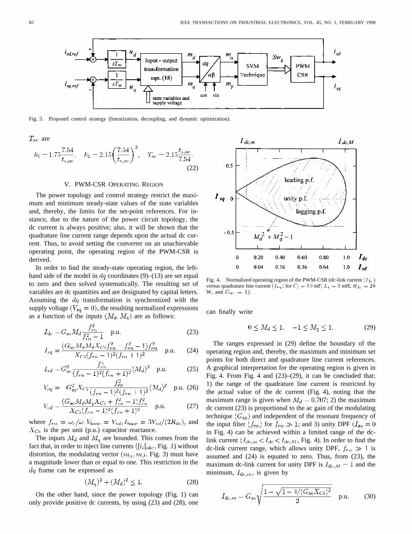
Fig. 3. Proposed control strategy (linearization, decoupling, and dynamic optimization).
are
(22)
V. PWM-CSR OPERATING REGION
The power topology and control strategy restrict the maxi-mum and minimum steady-state values of the state variablesand, thereby, the limits for the set-point references. For in-stance, due to the nature of the power circuit topology, thedc current is always positive; also, it will be shown that thequadrature line current range depends upon the actual dc cur-rent. Thus, to avoid setting the converter on an unachievableoperating point, the operating region of the PWM-CSR isderived.
In order to find the steady-state operating region, the left-hand side of the model in coordinates (9)–(13) are set equalto zero and then solved systematically. The resulting set ofvariables are dc quantities and are designated by capital letters.Assuming the transformation is synchronized with thesupply voltage the resulting normalized expressionsas a function of the inputs are as follows:
p.u. (23)
p.u. (24)
p.u. (25)
p.u. (26)
p.u. (27)
where andis the per unit (p.u.) capacitor reactance.
The inputs and are bounded. This comes from thefact that, in order to inject line currents Fig. 1) withoutdistortion, the modulating vector Fig. 3) must havea magnitude lower than or equal to one. This restriction in the
frame can be expressed as
(28)
On the other hand, since the power topology (Fig. 1) canonly provide positive dc currents, by using (23) and (28), one
Fig. 4. Normalized operating region of the PWM-CSR (dc-link current(Idc)versus quadrature line current(Isq) for Ci = 50 mF,Li = 3 mH,Rdc = 20W, andGac = 1):
can finally write
(29)
The ranges expressed in (29) define the boundary of theoperating region and, thereby, the maximum and minimum setpoints for both direct and quadrature line current references.A graphical interpretation for the operating region is given inFig. 4. From Fig. 4 and (23)–(29), it can be concluded that:1) the range of the quadrature line current is restricted bythe actual value of the dc current (Fig. 4), noting that themaximum range is given when 2) the maximumdc current (23) is proportional to the ac gain of the modulatingtechnique and independent of the resonant frequency ofthe input filter for and 3) unity DPFin Fig. 4) can be achieved within a limited range of the dc-link current Fig. 4). In order to find thedc-link current range, which allows unity DPF, isassumed and (24) is equated to zero. Thus, from (23), themaximum dc-link current for unity DPF is and theminimum, is given by
p.u (30)
ESPINOZA AND JOOS: STATE VARIABLE DECOUPLING AND POWER FLOW CONTROL IN PWM-CSR’s 83
(a)
(b)
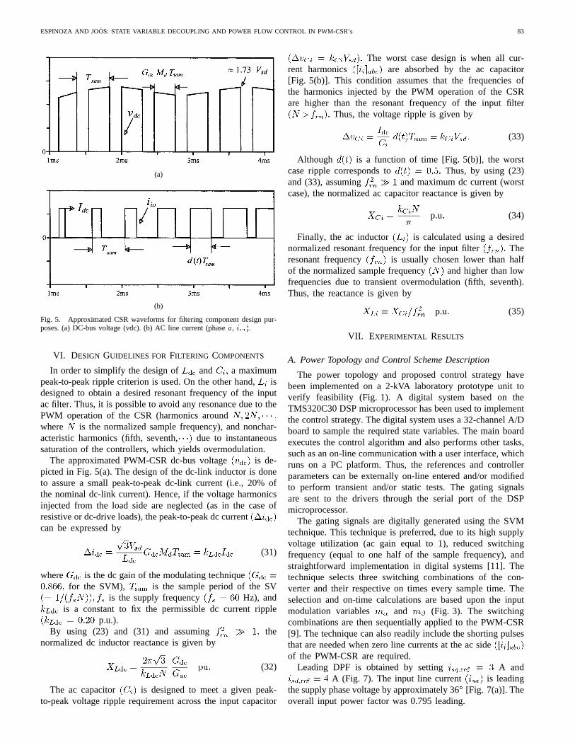
Fig. 5. Approximated CSR waveforms for filtering component design pur-poses. (a) DC-bus voltage (vdc). (b) AC line current (phasea, iia):
VI. DESIGN GUIDELINES FOR FILTERING COMPONENTS
In order to simplify the design of and a maximumpeak-to-peak ripple criterion is used. On the other hand,isdesigned to obtain a desired resonant frequency of the inputac filter. Thus, it is possible to avoid any resonance due to thePWM operation of the CSR (harmonics aroundwhere is the normalized sample frequency), and nonchar-acteristic harmonics (fifth, seventh, due to instantaneoussaturation of the controllers, which yields overmodulation.
The approximated PWM-CSR dc-bus voltage is de-picted in Fig. 5(a). The design of the dc-link inductor is doneto assure a small peak-to-peak dc-link current (i.e., 20% ofthe nominal dc-link current). Hence, if the voltage harmonicsinjected from the load side are neglected (as in the case ofresistive or dc-drive loads), the peak-to-peak dc currentcan be expressed by
(31)
where is the dc gain of the modulating techniquefor the SVM), is the sample period of the SV
is the supply frequency Hz), andis a constant to fix the permissible dc current ripple
p.u.).By using (23) and (31) and assuming the
normalized dc inductor reactance is given by
(32)
The ac capacitor is designed to meet a given peak-to-peak voltage ripple requirement across the input capacitor
The worst case design is when all cur-rent harmonics are absorbed by the ac capacitor[Fig. 5(b)]. This condition assumes that the frequencies ofthe harmonics injected by the PWM operation of the CSRare higher than the resonant frequency of the input filter
Thus, the voltage ripple is given by
(33)
Although is a function of time [Fig. 5(b)], the worstcase ripple corresponds to Thus, by using (23)and (33), assuming and maximum dc current (worstcase), the normalized ac capacitor reactance is given by
p.u (34)
Finally, the ac inductor is calculated using a desirednormalized resonant frequency for the input filter Theresonant frequency is usually chosen lower than halfof the normalized sample frequency and higher than lowfrequencies due to transient overmodulation (fifth, seventh).Thus, the reactance is given by
p.u (35)
VII. EXPERIMENTAL RESULTS
A. Power Topology and Control Scheme Description
The power topology and proposed control strategy havebeen implemented on a 2-kVA laboratory prototype unit toverify feasibility (Fig. 1). A digital system based on theTMS320C30 DSP microprocessor has been used to implementthe control strategy. The digital system uses a 32-channel A/Dboard to sample the required state variables. The main boardexecutes the control algorithm and also performs other tasks,such as an on-line communication with a user interface, whichruns on a PC platform. Thus, the references and controllerparameters can be externally on-line entered and/or modifiedto perform transient and/or static tests. The gating signalsare sent to the drivers through the serial port of the DSPmicroprocessor.
The gating signals are digitally generated using the SVMtechnique. This technique is preferred, due to its high supplyvoltage utilization (ac gain equal to 1), reduced switchingfrequency (equal to one half of the sample frequency), andstraightforward implementation in digital systems [11]. Thetechnique selects three switching combinations of the con-verter and their respective on times every sample time. Theselection and on-time calculations are based upon the inputmodulation variables and (Fig. 3). The switchingcombinations are then sequentially applied to the PWM-CSR[9]. The technique can also readily include the shorting pulsesthat are needed when zero line currents at the ac sideof the PWM-CSR are required.
Leading DPF is obtained by setting A andA (Fig. 7). The input line current is leading
the supply phase voltage by approximately 36[Fig. 7(a)]. Theoverall input power factor was 0.795 leading.

84 IEEE TRANSACTIONS ON INDUSTRIAL ELECTRONICS, VOL. 45, NO. 1, FEBRUARY 1998
(a)
(b)
(c)
(d)
Fig. 6. PWM-CSR unity DPF operating mode(isd;ref = 4 A, isq;ref = 0); experimental waveforms (see Fig. 1). (a) Supply voltage(vsa) and supplycurrent (10 isa): (b) Capacitor voltage(vca) and ac CSR current(10 iia): (c) CSR dc-bus voltage(vdc) and dc-link bus current(10 idc): (d) q andd line current references(isq;ref ; isd;ref ) and q and d actual line currents(isq ; isd):
B. Filter Components and Controller Parameters Design
The minimum sample time in this setup is 185s. There-fore, a sample frequency of 5040 Hz (sample period of 198s)is chosen Both and line current controllersare designed to achieve a 5-ms settling time ms).
Thus, by using (22), M, andm.
The selection of and is done by following the de-sign guidelines provided in Section VI. Thus, assuming
peak-to-peak current ripple under the worst
ESPINOZA AND JOOS: STATE VARIABLE DECOUPLING AND POWER FLOW CONTROL IN PWM-CSR’s 85
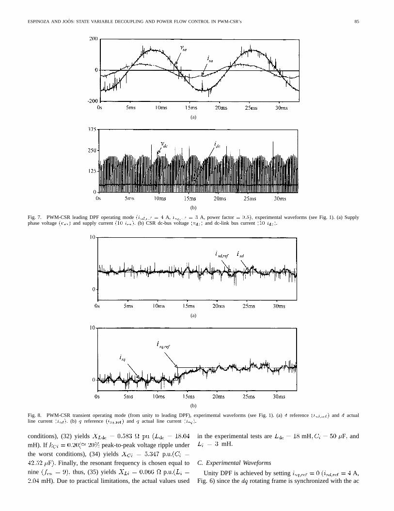
(a)
(b)
Fig. 7. PWM-CSR leading DPF operating mode(isd;ref = 4 A, isq;ref = 3 A, power factor= 0:8); experimental waveforms (see Fig. 1). (a) Supplyphase voltage(vsa) and supply current(10 isa): (b) CSR dc-bus voltage(vdc) and dc-link bus current(10 idc):
(a)
(b)
Fig. 8. PWM-CSR transient operating mode (from unity to leading DPF), experimental waveforms (see Fig. 1). (a)d reference(isd;ref ) and d actualline current (isd): (b) q reference(isq;ref) and q actual line current(isq):
conditions), (32) yieldsmH). If peak-to-peak voltage ripple underthe worst conditions), (34) yields p.u.
F Finally, the resonant frequency is chosen equal tonine thus, (35) yields p.u.
mH). Due to practical limitations, the actual values used
in the experimental tests are mH F andmH
C. Experimental Waveforms
Unity DPF is achieved by setting A,Fig. 6) since the rotating frame is synchronized with the ac

86 IEEE TRANSACTIONS ON INDUSTRIAL ELECTRONICS, VOL. 45, NO. 1, FEBRUARY 1998
(A2)
mains. The supply line current is in phase with the phasevoltage [Fig. 6(a)]. However, a small distortion is observed inthe line current , which results in a overall input powerfactor equal to 0.972. The CSR ac current and dc-busvoltage are of the PWM type [Fig. 6(b) and (c)], due tothe use of the SVM technique. Thus, the distortion introducedon the load and supply system is minimized. Bothandactual current components are equal to the references, hence,unity DPF is achieved [Fig. 6(d)]. It should be noted that thereis a fair amount of noise, both radiated and conducted, in apower converter environment. It may, therefore, be difficultto record clean signals. However, measuring voltages directlyacross capacitors minimizes noise pickup.
Finally, a step increase in at ms (from 0 to 3A), while is set at 4 A, illustrates key dynamic features.Fig. 8 shows the and line current references and actualvalues. It can be seen that thecomponent is not modifiedduring the transient [Fig. 8(a)]. This confirms the decouplingand independent control of the active and reactive power. Thesettling time is found to be approximately 5 ms [Fig. 8(b)],which confirms the validity of the design guidelines of theline current component controllers. The results all indicatethat the damping resistors on the input filter are no longernecessary. The required damping is supplied by the statevariable feedback compensation. Similar tests were done fordifferent operating points and they all showed similar transientresponses, which confirms full linearization obtained throughthe input transformation.
VIII. C ONCLUSIONS
Simple and direct on-line control of a current-source rec-tifier is designed to regulate the ac line currents directly inthe stationary frame. This paper has demonstrated thesuperiority of the proposed control technique, which featuresthe following: 1) control in a rotating frame; 2) a decouplingbetween and components; and 3) the use of a nonlineartransformation to linearize the model. Furthermore, the useof DSP hardware and software greatly simplifies the imple-mentation of the proposed control technique. It also allowsintegration of control functions and PWM pattern generation.Results on a 2-kVA prototype indicate the following: 1) com-plete and accurate displacement power factor control; 2) fast,accurate, and independent control of theand line currentcomponents; and 3) low-input current harmonic distortion.
APPENDIX
INTERNAL DYNAMICS STABILITY ANALYSIS
The internal dynamicscorresponds to the dc-link currentdifferential equation given by
(A1)
On the other hand, the modulating vector given by(18) can be written, using (19), as (A2), at the top of the page.
The internal dynamics(A1) is stable if the dc-link currentis bounded for any arbitrary but bounded modulating
vector However, there is an intrinsic property ofnonlinear systems of considering theinternal dynamicswhenthe control inputs are such that the outputs aremaintained constant (i.e., [15]. Consequently,their time derivatives are also zero. Under these circumstances,the capacitor voltages are also constant (i.e.,Thus, the modulating vector can be written as
(A3)
where and are constants introduced to simplify the restof the analysis. Replacing (A3) into (A1), we obtain
(A4)
By defining replacing it into (A4), and solving theresulting first-order differential equation, it is found that
(A5)
Since the expression for the dc-link currentbecomes
(A6)
The expression for (A6) is bounded, sincealways converge. Therefore, theinternal
dynamicsis said to be locally asymptotically stable [15]. Notethat the load has been modeled by a resistor The analysisto include active loads is beyond the scope of this paper.
REFERENCES
[1] C. Namuduri and P. Sen, “Optimal pulse width modulation for currentsource inverters,”IEEE Trans. Ind. Applicat.,vol. IA-22, pp. 1052–1072,Nov./Dec. 1986.
[2] H. Karshenas, H. Kojori, and S. Dewan, “Generalized techniques ofselective harmonic elimination and current control in current source in-verters/converters,”IEEE Trans. Power Electron.,vol. 10, pp. 566–573,Sept. 1995.
[3] P. Enjeti, P.D. Ziogas, and J. Lindsay, “A current source PWM in-verter with instantaneous current control capability,”IEEE Trans. Ind.Applicat., vol. 27, pp. 893–643, May/June 1991.
[4] Y. Sato and T. Kataoka, “State feedback control of current type PWMac-to-dc converters,”IEEE Trans. Ind. Applicat.,vol. 29, pp. 1090–1097,Nov./Dec. 1993.
ESPINOZA AND JOOS: STATE VARIABLE DECOUPLING AND POWER FLOW CONTROL IN PWM-CSR’s 87
[5] X. Wang and B. Ooi, “Real-time multi-DSP control of three-phasecurrent-source unity power factor PWM rectifier,”IEEE Trans. PowerElectron.,vol. 8, pp. 295–300, July 1993.
[6] S. Hiti, V. Vlatkovic. D. Borojevic, and F. Lee, “A new controlalgorithm for three-phase PWM buck rectifier with input displacementfactor compensation,”IEEE Trans. Power Electron.,vol. 9, pp. 173–180,Mar. 1994.
[7] Y. Sato and T. Kataoka, “A current type PWM rectifier with activedamping function,”IEEE Trans. Ind. Applicat.,vol. 32, pp. 553–541,May/June 1996.
[8] N. Zargari and G. Joos, “An on-line operated near unity power factorPWM rectifier with minimum control requirements,” inConf. Rec. IEEEIECON’94, 1994, pp. 593–598.
[9] J. Holtz, “Pulsewidth modulation—A survey,”IEEE Trans. Ind. Elec-tron., vol. 39, pp. 410–420, Oct. 1992.
[10] V. Vlatkovic and D. Borojevic, “Digital-signal-processor-based controlof three-phase space vector modulated converters,”IEEE Trans. Ind.Electron.,vol. 41, pp. 326–332, June 1994.
[11] J. Espinoza and G. Jo´os, “Current-source converter on-line pattern gen-erator switching frequency minimization,”IEEE Trans. Ind. Electron.,vol. 44, pp. 198–206, Apr. 1997.
[12] M. Kazmierkowski and M. Dzieniakowski, “Review of current regu-lation methods for VS-PWM inverters,” inConf. Rec. IEEE ISIE’93,1993, pp. 448–456.
[13] D. Liebal, P. Vijayraghavan, and N. Sreenath, “Control of dc-dc buck-boost converter using exact linearization techniques,” inConf. Rec. IEEEPESC’93,June 1993, pp. 203–207.
[14] P. Rioual and H. Pouliquen, “Non linear control of PWM rectifier bystate feedback linearization and exact PWM control,” inConf. Rec. IEEEPESC’94,June 1994, pp. 1095–1102.
[15] J. Slotine and W. Li,Applied Nonlinear Control. Englewood Cliffs,NJ: Prentice-Hall, 1991, ch. 6.
[16] R. Dorf,Modern Control Systems,Reading, MA: Addison-Wesley, 1992,ch. 4.
Jose R. Espinoza(S’93–M’98) was born in Con-cepcion, Chile, in 1965. He received the Eng. degree(with first-class honors) in electronic engineeringand the M.Sc. degree in electrical engineering fromthe University of Concepcion, Concepcion, Chile, in1989 and 1992, respectively, and the Ph.D. degreein electrical engineering from Concordia University,Montreal, P.Q., Canada, in 1997.
He is currently an Assistant Professor in theDepartamento de Ingenierıa Electrica, Universidadde Concepci´on, Concepci´on, Chile. His research
interests include the modeling and control of static power converters andsystems.
Geza Joos (M’78–SM’89) received the M.Eng. andPh.D. degrees from McGill University, Montreal,P.Q., Canada, in 1974 and 1987, respectively.
Since 1988, he has been with the Departmentof Electrical and Computer Engineering, ConcordiaUniversity, Montreal, P.Q., Canada, where he isengaged in teaching and research in the areas ofpower converters and electrical drives. From 1975 to1978, he was a Design Engineer with Brown BoveriCanada and, from 1978 to 1988, he was a Professorat the Ecole de Technologie Superieure, Montreal,P.Q., Canada.
Copyright © 2022 FDOKUMEN