Cordex 48-1.2kW Rectifier Shelf Systems
92
Your Power Solutions Partner Cordex 48-1.2kW Rectifier Shelf Systems Installation Manual Part # 010-619-J0 Effective: 11/2016 member of The Group ™
-
Upload
khangminh22 -
Category
Documents
-
view
3 -
download
0
Transcript of Cordex 48-1.2kW Rectifier Shelf Systems
Your Power Solutions Partner
Cordex 48-1.2kW Rectifier Shelf Systems
Installation Manual Part # 010-619-J0
Effective: 11/2016
member of The Group™


Cordex 48-1.2kW Rectifier Shelf Systems ManualNOTE: Photographs contained in this manual are for illustrative purposes only. These photographs may not match your installation.
NOTE: Operator is cautioned to review the drawings and illustrations contained in this manual before proceeding. If there are questions regarding the safe operation of this powering system, contact Alpha Technologies or your nearest Alpha representative.
NOTE: Alpha shall not be held liable for any damage or injury involving its enclosures, power supplies, generators, batteries, or other hardware if used or operated in any manner or subject to any condition inconsistent with its intended purpose, or if installed or operated in an unapproved manner, or improp-erly maintained.
Copyright
Copyright © 2016 Alpha Technologies Ltd. All rights reserved. Alpha is a registered trademark of Alpha Technologies.
No part of this documentation shall be reproduced, stored in a retrieval system, translated, transcribed, or transmitted in any form or by any means manual, electric, electronic, electromechanical, chemical, optical, or other-wise without prior explicit written permission from Alpha Technologies.
This document, the software it describes, and the information and know-how they contain constitute the proprietary, confidential and valuable trade secret information of Alpha Technologies, and may not be used for any unauthorized purpose, or disclosed to others without the prior written permission of Alpha Technologies.
The material contained in this document is for information only and is subject to change without notice. While reasonable efforts have been made in the preparation of this document to assure its accuracy, Alpha Technologies assumes no liability resulting from errors or omissions in this document, or from the use of the information contained herein. Alpha Technologies reserves the right to make changes in the product design without reservation and without notification to its users.


TABLE OF CONTENTS
1 SAFETY . . . . . . . . . . . . . . . . . . . . . . . . . . . . . . . . . . . . . 1Safety Wording/Symbols . . . . . . . . . . . . . . . . . . . . . . . . . . . . 1General Warning and Cautions . . . . . . . . . . . . . . . . . . . . . . . . . 1Electrical Safety . . . . . . . . . . . . . . . . . . . . . . . . . . . . . . . . . 1Battery Safety . . . . . . . . . . . . . . . . . . . . . . . . . . . . . . . . . . 2
2 INTRODUCTION . . . . . . . . . . . . . . . . . . . . . . . . . . . . . . . . . . 3Scope of the Manual . . . . . . . . . . . . . . . . . . . . . . . . . . . . . . 3Product Overview . . . . . . . . . . . . . . . . . . . . . . . . . . . . . . . . 3
3 FEATURES . . . . . . . . . . . . . . . . . . . . . . . . . . . . . . . . . . . . 5Rectifier . . . . . . . . . . . . . . . . . . . . . . . . . . . . . . . . . . . . . 5
Rectifier Front Panel . . . . . . . . . . . . . . . . . . . . . . . . . . . . . 5LEDs . . . . . . . . . . . . . . . . . . . . . . . . . . . . . . . . . . . . . 5Mechanical . . . . . . . . . . . . . . . . . . . . . . . . . . . . . . . . . . 6True Module Fail Alarm . . . . . . . . . . . . . . . . . . . . . . . . . . . 6Heat Dissipation . . . . . . . . . . . . . . . . . . . . . . . . . . . . . . . 6Over Temperature Protection . . . . . . . . . . . . . . . . . . . . . . . . 6Wide AC Range . . . . . . . . . . . . . . . . . . . . . . . . . . . . . . . 6AC Inrush/Transient Suppression . . . . . . . . . . . . . . . . . . . . . . 7Soft Start . . . . . . . . . . . . . . . . . . . . . . . . . . . . . . . . . . . 7Start Delay . . . . . . . . . . . . . . . . . . . . . . . . . . . . . . . . . . 7Current Limit/Short Circuit Protection . . . . . . . . . . . . . . . . . . . . 7Power Limiting . . . . . . . . . . . . . . . . . . . . . . . . . . . . . . . . 7High Voltage Shutdown (HVSD) . . . . . . . . . . . . . . . . . . . . . . . 7Battery Eliminator Operation . . . . . . . . . . . . . . . . . . . . . . . . . 7
Distribution . . . . . . . . . . . . . . . . . . . . . . . . . . . . . . . . . . . 84.8kW System Distribution Module . . . . . . . . . . . . . . . . . . . . . 83.6kW System Distribution Module . . . . . . . . . . . . . . . . . . . . . 8
Overview of the CXCM1 HP . . . . . . . . . . . . . . . . . . . . . . . . . . . 9Display . . . . . . . . . . . . . . . . . . . . . . . . . . . . . . . . . . . . 9In-Shelf Display: Menu . . . . . . . . . . . . . . . . . . . . . . . . . . . . 10In-Shelf Controller Buttons . . . . . . . . . . . . . . . . . . . . . . . . . . 11
Overview of the CXCM1+ . . . . . . . . . . . . . . . . . . . . . . . . . . . . 12CXCM1+ Controller Front Panel . . . . . . . . . . . . . . . . . . . . . . . 12LCD Screen . . . . . . . . . . . . . . . . . . . . . . . . . . . . . . . . . 13LEDs . . . . . . . . . . . . . . . . . . . . . . . . . . . . . . . . . . . . . 13Reset (CXCM1+ only) . . . . . . . . . . . . . . . . . . . . . . . . . . . . 13Ethernet Port . . . . . . . . . . . . . . . . . . . . . . . . . . . . . . . . . 14Analog Input Channels . . . . . . . . . . . . . . . . . . . . . . . . . . . 14Digital Input Channels . . . . . . . . . . . . . . . . . . . . . . . . . . . . 14Alarm and Control Output Relays . . . . . . . . . . . . . . . . . . . . . . 14
i

Network Connection and Remote Communication . . . . . . . . . . . . . 14Controller Connections . . . . . . . . . . . . . . . . . . . . . . . . . . . 15
4 INSPECTION . . . . . . . . . . . . . . . . . . . . . . . . . . . . . . . . . . . 17Check for Damage . . . . . . . . . . . . . . . . . . . . . . . . . . . . . . . 17Packing Materials . . . . . . . . . . . . . . . . . . . . . . . . . . . . . . . . 17Returns for Service . . . . . . . . . . . . . . . . . . . . . . . . . . . . . . . 17
5 INSTALLATION . . . . . . . . . . . . . . . . . . . . . . . . . . . . . . . . . . 19Safety Precautions . . . . . . . . . . . . . . . . . . . . . . . . . . . . . . . 19Shelf Preparation/Mounting . . . . . . . . . . . . . . . . . . . . . . . . . . . 19Module Insertion/Removal . . . . . . . . . . . . . . . . . . . . . . . . . . . 19Removing a CXRF . . . . . . . . . . . . . . . . . . . . . . . . . . . . . . . 20Removing Older Model CXRF or CXCM1+ . . . . . . . . . . . . . . . . . . . 20Removing the CXCM1 HP . . . . . . . . . . . . . . . . . . . . . . . . . . . 21
6 WIRING AND CONNECTIONS . . . . . . . . . . . . . . . . . . . . . . . . . . . . 23Safety Precautions . . . . . . . . . . . . . . . . . . . . . . . . . . . . . . . 23Tools Required . . . . . . . . . . . . . . . . . . . . . . . . . . . . . . . . . 23AC Feeder Protection/Sizing . . . . . . . . . . . . . . . . . . . . . . . . . . 23AC Input . . . . . . . . . . . . . . . . . . . . . . . . . . . . . . . . . . . . . 24
Strain Relief . . . . . . . . . . . . . . . . . . . . . . . . . . . . . . . . . 24Calculating Output Wire Size Requirements . . . . . . . . . . . . . . . . . . 25DC Output . . . . . . . . . . . . . . . . . . . . . . . . . . . . . . . . . . . . 25
DC Output for Model 030-851-20 (maximum 3600W) . . . . . . . . . . . . 25DC Output for Model 030-834-20 (maximum 4800W) . . . . . . . . . . . . 27DC Output for Model 030-835-20/ 030-845-20 (bulk distribution) . . . . . . 30
CAN Ports . . . . . . . . . . . . . . . . . . . . . . . . . . . . . . . . . . . . 30Network Connection and Remote Communications via CXC . . . . . . . . . . 30
Ethernet Port for Network Connection . . . . . . . . . . . . . . . . . . . . 30Ethernet Port for Local Connection . . . . . . . . . . . . . . . . . . . . . 30
Signal Wiring Connections . . . . . . . . . . . . . . . . . . . . . . . . . . . 30Analog Inputs . . . . . . . . . . . . . . . . . . . . . . . . . . . . . . . . 31Digital Inputs . . . . . . . . . . . . . . . . . . . . . . . . . . . . . . . . . 31Alarm (Relay) Outputs . . . . . . . . . . . . . . . . . . . . . . . . . . . . 32LVD Control (Load Disconnect or Battery Disconnect) . . . . . . . . . . . 33LVD Control Alternative . . . . . . . . . . . . . . . . . . . . . . . . . . . 33
7 OPERATION . . . . . . . . . . . . . . . . . . . . . . . . . . . . . . . . . . . 35Main Rectifier States . . . . . . . . . . . . . . . . . . . . . . . . . . . . . . 35
Off . . . . . . . . . . . . . . . . . . . . . . . . . . . . . . . . . . . . . . 35Start Delay . . . . . . . . . . . . . . . . . . . . . . . . . . . . . . . . . . 35Soft Start . . . . . . . . . . . . . . . . . . . . . . . . . . . . . . . . . . . 35Normal Operation . . . . . . . . . . . . . . . . . . . . . . . . . . . . . . 35Turning Off . . . . . . . . . . . . . . . . . . . . . . . . . . . . . . . . . . 36
ii
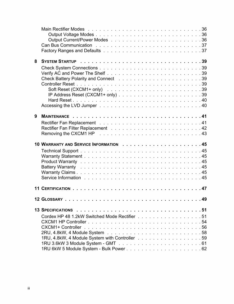
Main Rectifier Modes . . . . . . . . . . . . . . . . . . . . . . . . . . . . . . 36Output Voltage Modes . . . . . . . . . . . . . . . . . . . . . . . . . . . . 36Output Current/Power Modes . . . . . . . . . . . . . . . . . . . . . . . . 36
Can Bus Communication . . . . . . . . . . . . . . . . . . . . . . . . . . . . 37Factory Ranges and Defaults . . . . . . . . . . . . . . . . . . . . . . . . . . 37
8 SYSTEM STARTUP . . . . . . . . . . . . . . . . . . . . . . . . . . . . . . . . 39Check System Connections . . . . . . . . . . . . . . . . . . . . . . . . . . . 39Verify AC and Power The Shelf . . . . . . . . . . . . . . . . . . . . . . . . . 39Check Battery Polarity and Connect . . . . . . . . . . . . . . . . . . . . . . 39Controller Reset . . . . . . . . . . . . . . . . . . . . . . . . . . . . . . . . . 39
Soft Reset (CXCM1+ only) . . . . . . . . . . . . . . . . . . . . . . . . . 39IP Address Reset (CXCM1+ only) . . . . . . . . . . . . . . . . . . . . . . 39Hard Reset . . . . . . . . . . . . . . . . . . . . . . . . . . . . . . . . . . 40
Accessing the LVD Jumper . . . . . . . . . . . . . . . . . . . . . . . . . . . 40
9 MAINTENANCE . . . . . . . . . . . . . . . . . . . . . . . . . . . . . . . . . . 41Rectifier Fan Replacement . . . . . . . . . . . . . . . . . . . . . . . . . . . 41Rectifier Fan Filter Replacement . . . . . . . . . . . . . . . . . . . . . . . . 42Removing the CXCM1 HP . . . . . . . . . . . . . . . . . . . . . . . . . . . 43
10 WARRANTY AND SERVICE INFORMATION . . . . . . . . . . . . . . . . . . . . . 45Technical Support . . . . . . . . . . . . . . . . . . . . . . . . . . . . . . . . 45Warranty Statement . . . . . . . . . . . . . . . . . . . . . . . . . . . . . . . 45Product Warranty . . . . . . . . . . . . . . . . . . . . . . . . . . . . . . . . 45Battery Warranty . . . . . . . . . . . . . . . . . . . . . . . . . . . . . . . . 45Warranty Claims . . . . . . . . . . . . . . . . . . . . . . . . . . . . . . . . . 45Service Information . . . . . . . . . . . . . . . . . . . . . . . . . . . . . . . 45
11 CERTIFICATION . . . . . . . . . . . . . . . . . . . . . . . . . . . . . . . . . . 47
12 GLOSSARY . . . . . . . . . . . . . . . . . . . . . . . . . . . . . . . . . . . . 49
13 SPECIFICATIONS . . . . . . . . . . . . . . . . . . . . . . . . . . . . . . . . . 51Cordex HP 48 1.2kW Switched Mode Rectifier . . . . . . . . . . . . . . . . . 51CXCM1 HP Controller . . . . . . . . . . . . . . . . . . . . . . . . . . . . . . 54CXCM1+ Controller . . . . . . . . . . . . . . . . . . . . . . . . . . . . . . . 562RU, 4.8kW, 4 Module System . . . . . . . . . . . . . . . . . . . . . . . . . 581RU, 4.8kW, 4 Module System with Controller . . . . . . . . . . . . . . . . . 591RU 3.6kW 3 Module System - GMT . . . . . . . . . . . . . . . . . . . . . . 611RU 6kW 5 Module System - Bulk Power . . . . . . . . . . . . . . . . . . . . 62
iii
iv
LIST OF FIGURES
Figure 1: Single Shelf . . . . . . . . . . . . . . . . . . . . . . . . . . . . . . . . . . 4Figure 2: Dual Shelf. . . . . . . . . . . . . . . . . . . . . . . . . . . . . . . . . . . 4Figure 3: 2RU Shelf . . . . . . . . . . . . . . . . . . . . . . . . . . . . . . . . . . . 4Figure 4: Rectifier Front Panel . . . . . . . . . . . . . . . . . . . . . . . . . . . . . 5Figure 5: 4.8kW System Distribution Module . . . . . . . . . . . . . . . . . . . . . . 8Figure 6: 3.6kW System Distribution Module . . . . . . . . . . . . . . . . . . . . . . 8Figure 7: CXCM1 HP Controller . . . . . . . . . . . . . . . . . . . . . . . . . . . . 9Figure 8: In-Shelf Controller Dashboard Screens. . . . . . . . . . . . . . . . . . . .10Figure 9: In-Shelf Controller Menu . . . . . . . . . . . . . . . . . . . . . . . . . . .10Figure 10: In-Shelf Controller Buttons: Vertical Mount . . . . . . . . . . . . . . . . . .11Figure 11: In-Shelf Controller Buttons: Horizontal Mount . . . . . . . . . . . . . . . .11Figure 12: Cordex CXCM1+ model system controller front panel . . . . . . . . . . . .13Figure 13: Packing Materials and Environmental Codes . . . . . . . . . . . . . . . .17Figure 14: Removing a Rectifier from the Shelf . . . . . . . . . . . . . . . . . . . . .20Figure 15: Removing a CXRF or CXCM1 or CXCM1+. . . . . . . . . . . . . . . . . .21Figure 16: Removing the CXCM1 HP . . . . . . . . . . . . . . . . . . . . . . . . . .22Figure 17: (4800W system) AC input, CAN, and signal connections . . . . . . . . . .24Figure 18: AC Cord Strain Relief . . . . . . . . . . . . . . . . . . . . . . . . . . . . .25Figure 19: DC Output Connections . . . . . . . . . . . . . . . . . . . . . . . . . . .26Figure 20: DC Output to Batteries . . . . . . . . . . . . . . . . . . . . . . . . . . . .27Figure 21: DC Output Connections . . . . . . . . . . . . . . . . . . . . . . . . . . .28Figure 22: Breaker Return Connections . . . . . . . . . . . . . . . . . . . . . . . . .29Figure 23: Front View of Distribution Module (Cover Removed) . . . . . . . . . . . . .29Figure 24: Signal Wiring Terminal Blocks . . . . . . . . . . . . . . . . . . . . . . . .31Figure 25: Digital Input Connection Method . . . . . . . . . . . . . . . . . . . . . . .32Figure 26: Relay Connections . . . . . . . . . . . . . . . . . . . . . . . . . . . . . .33Figure 27: Rectifier Fan Replacement . . . . . . . . . . . . . . . . . . . . . . . . . .41Figure 28: Rectifier Fan Filter Replacement . . . . . . . . . . . . . . . . . . . . . . .42Figure 29: Removing the CXCM1 HP . . . . . . . . . . . . . . . . . . . . . . . . . .43

LIST OF TABLES
Table 1: In-Shelf Controller Full Menu . . . . . . . . . . . . . . . . . . . . . . . . .10Table 2: Recommended AC Supply Configuration. . . . . . . . . . . . . . . . . . .24Table 3: Voltage Level Definitions for Digital Inputs . . . . . . . . . . . . . . . . . .32Table 4: Output Voltage Modes . . . . . . . . . . . . . . . . . . . . . . . . . . . .36Table 5: Output Current/Power Modes. . . . . . . . . . . . . . . . . . . . . . . . .36Table 6: Factory Ranges and Defaults. . . . . . . . . . . . . . . . . . . . . . . . .37Table 7: Sample Maintenance Log. . . . . . . . . . . . . . . . . . . . . . . . . . .41Table 8: Specifications: Cordex HP 48 1.2kW, Switched Mode Rectifier . . . . . . .51Table 9: Specifications: CXCM1 HP Controller . . . . . . . . . . . . . . . . . . . .54Table 10: Specifications: CXCM1+ Controller . . . . . . . . . . . . . . . . . . . . . .56Table 11: Specifications: 48-1.2kW 19”, 2RU, 4.8kW, 4 Module System . . . . . . . .58Table 12: Specifications: 48-1.2kW 19”, 1RU, 4.8kW, 4 Module System . . . . . . . .59Table 13: Specifications: 48-1.2kW 19”, 1RU, 3.6kW, 3 Module System . . . . . . . .61Table 14: Specifications: 48-1.2kW 19”, 1RU, 6kW, 5 Module System . . . . . . . . .62
v

vi

1 SafetySAVE THESE INSTRUCTIONS: This manual contains important safety instructions that must be followed during the installation, servicing, and maintenance of the product. Keep it in a safe place. Review the drawings and illustrations contained in this manual before proceeding. If there are any ques-tions regarding the safe installation or operation of this product, contact Alpha Technologies or the nearest Alpha representative.
1.1 Safety Wording/SymbolsTo reduce the risk of injury or death, and to ensure the continued safe operation of this product, the following symbols have been placed throughout this manual. Where these symbols appear, use extra care and attention.
ATTENTION: The use of attention indicates specific regulatory/code requirements that may affect the placement of equipment and /or installation procedures.
NOTE: Notes provide additional information to help complete a specific task or procedure.
CAUTION: Cautions indicate safety information intended to PREVENT DAMAGE to material or equip-ment.
WARNING: Warnings present safety information to PREVENT INJURY OR DEATH to personnel.
NOTE: HOT! The use of Hot presents safety information to PREVENT BURNS to the technician or user.
1.2 General Warning and CautionsWARNING: You must read and understand the following warnings before installing the system and its components. Failure to do so could result in personal injury or death.
• Read and follow all instructions included in this manual.
• Only trained personnel are qualified to install or replace this equipment and its components.
• Use proper lifting techniques whenever handling equipment, parts, or batteries.
• To be installed in a restricted access location that is inaccessible to the general public.
1.3 Electrical SafetyWARNING: Hazardous voltages are present at the input of power systems. The DC output from some rectifiers and batteries can have high voltage and high short-circuit current capacity that may cause severe burns and electrical arcing.
Before working with any live battery or power system, follow these precautions:
• Remove all metallic jewelry, such as watches, rings, metal rimmed glasses, or necklaces.
• Wear safety glasses with side shields at all times during the installation.
• Use OSHA approved insulated hand tools. Do not rest tools on top of batteries.
010-619-J0 Rev A Page 1

WARNING: Lethal voltages are present within the power system. Always assume that an electrical connection or conductor is energized. Check the circuit with a voltmeter with respect to the grounded portion of the enclosure (both AC and DC) before performing any installation or removal procedure.
• Do not work alone under hazardous conditions.
• A licensed electrician is required to install permanently wired equipment. Input voltages can range up to 480VAC Vac. Ensure that the utility power is disconnected and locked out before performing any installation or removal procedure.
• Ensure that no liquids or wet clothes come into contact with internal components.
• Hazardous electrically live parts inside this unit are energized from the batteries even when the AC input power is disconnected.
• The enclosure which contains the DC or AC power system along with customer installed radios must remain locked at all times, except when authorized service personnel are present.
• Always assume electrical connections or conductors are live. Turn off all circuit breakers and double-check with a voltmeter before performing installation or maintenance.
• Place a warning label on the utility panel to warn emergency personnel that a reserve battery source is present which will power the loads in a power outage condition or if the AC disconnect breaker is turned off.
• At high ambient temperature conditions, the internal temperature can be hot so use caution when touching the equipment.
1.4 Battery Safety• Never transport an enclosure with batteries installed. Batteries must ONLY be installed after the
enclosure has been securely set in place at its permanent installation location. Transporting the unit with batteries installed may cause a short circuit, fire, explosion, and/or damage to the battery pack, enclosure and installed equipment.
• Servicing and connection of batteries must be performed by, or under the direct supervision of, personnel knowledgeable of batteries and the required safety precautions.
• Batteries contain or emit chemicals known to cause cancer and birth defects or other reproductive harm. Battery post terminals and related accessories contain lead and lead compounds. Wash your hands after handling batteries.
WARNING: Follow battery manufacturer’s safety recommendations when working around battery systems. Do not smoke or introduce an open flame when batteries (especially vented batteries) are charging. When charging, batteries vent hydrogen gas, which can explode.
• Batteries are hazardous to the environment and should be disposed at a recycling facility. Consult the battery manufacturer for recommended local authorized recyclers.
010-619-J0 Rev A Page 2

2 Introduction
2.1 Scope of the ManualThis manual explains the installation, interconnection, and operation of the Alpha Cordex CXRF-HP 48-1.2 kW 48Vdc power and distribution systems that contain the CXCM1 series of controllers (includes CXCM1+ and CXCM1 HP).
2.2 Product OverviewThese 48Vdc power and distribution systems incorporate the high performance (HP) series of 48V 1.2kW Cordex rectifier modules and are specifically designed for restricted space installation. Cordex rectifier modules use a high frequency, switched mode conversion technique to provide a fully regulated and isolated DC output from the AC mains. The rectifier module input is universal to allow use on 120/208/220/240Vac 50/60Hz electrical service. The front access design, allows for all customer connections in front of the rack channel.
• Rectifier power modules are “hot swappable”—they can be inserted or removed from the shelf without cutting power to or from the system or the load.
• Additional power modules can be added to the system at the time of ordering or after the shelf has been installed.
• The shelves are designed for horizontal mounting in a 19" or 23" center mount (flush mount for 1RU shelves) installation via universal mounting brackets (EIA rack spacing) and utilize dual IEC-type connectors for multiple AC line cord solutions.
• The Alpha CXCM1 HP was designed as a modular, high performance controller for the rectifier series.
• All controllers models allow the user to set up, control and monitor the entire power system and ancillary components from one central, easy-to-use source. Details of controller operation are provided in the current version software manual.
• The equipment is suitable for installation in network telecommunication facilities.
The following figures are examples of:
1. CXRF-HP 48-1.2 kW 1RU 19" shelf system, with 3 rectifier modules up to 3.6kW output power, CXCM1 HP controller and GMT fuse distribution
2. CXRF-HP 48-1.2 kW 1RU 19" shelf system, with (a) 4 rectifier modules up to 4.8W output power and controller (top shelf) and (b) 5 rectifier modules up to 6.0kW output power (lower shelf)
3. CXRF-HP 48-1.2kW 2RU 19" shelf system, with 4 rectifier modules up to 4.8kW output power, controller and breaker/GMT fuse distribution
010-619-J0 Rev A Page 3

Figure 1: Single Shelf
Figure 2: Dual Shelf
Figure 3: 2RU Shelf
010-619-J0 Rev A Page 4

3 Features
3.1 RectifierThe Cordex CXRF-HP series of 48V 1.2kW rectifier modules employ an advanced resonant power conversion technology featuring high power conversion efficiency. All internal semiconductor devices operate under “soft-switching” conditions and exhibit very low power loss. The reduced power loss leads to lower thermal stress on the semiconductors and thus improves reliability.
Sustaining low component temperatures is again the primary factor with meeting the three worst-case field scenarios: (1) 65°C ambient temperatures, (2) full output power, and (3) low AC input (176Vac). While meeting these specifications, Cordex rectifiers also offer roughly twice the reliability at 55°C and up to four times more at 45°C ambient temperature.
3.1.1 Rectifier Front PanelFigure 4: Rectifier Front Panel
3.1.2 LEDsThe front panel LEDs provide rectifier status summary and help to locate a specific module under CXC control.
AC
The top LED (green) is on when AC is within valid range and the rectifier is delivering power to the load. The LED will flash (~2Hz) when AC is outside the nominal range – AC voltage is invalid if the AC Mains Low or AC Mains High alarm is active. The LED turns off when AC has failed (or no AC power is present).
DC
The middle LED (green) is on when the rectifier is delivering power to the load. The LED turns off when the rectifier is off; e.g., when commanded via the CXC.
Alarm
The bottom LED (red) is on continuously in the event of an active Module Fail alarm. The LED flashes (~2Hz) when a minor alarm is detected. The LED remains off in the absence of an alarm. If the unit output is not connected to a battery or parallel rectifier, the LED extinguishes if no AC power is present.
LED Activity During “Locate Module” Command from CXC
010-619-J0 Rev A Page 5

When the “locate module” command has been received from the CXC, the LEDs behave in a distinctly different way so that the rectifier is easier to visually identify among adjacent rectifiers.
This state is entered when commanded via the CXC. The LEDs flash in a distinct pattern repeating every two seconds.
LED Activity During Firmware Upload
When a rectifier firmware upload is in progress, the LEDs behave in the same way as the locate module command described above.
3.1.3 MechanicalA locking clip automatically secures the rectifier into the shelf.
3.1.4 True Module Fail AlarmThe power modules have a “true” fail alarm. This provides a true indication of the power module’s ability to source current. When the module’s output current drops below 2.5% of the rated output a low output current condition is detected and the Module Fail detection circuit is activated. This circuit momentarily ramps up the output voltage to determine if the module will source current. If no increase in current is detected, the Module Fail alarm is activated. The module will test once every 60 seconds for the condi-tion until current is detected. Output voltage ramping will cease upon detection of current1. A minimum 2.5% load is required to avoid the Ramp Test Fail alarm; this can typically be provided with the parallel system battery. Activation of this alarm could indicate a failed module or a failed load.
NOTE: For Cordex rectifier systems without batteries (or with a very light load; below 2.5% of rated output) it is recommended that the ramp test be disabled to avoid nuisance alarms. The Ramp Test feature is enabled/disabled via the controller. Refer to the software manual for detailed information.
3.1.5 Heat DissipationCooling of the module is front-to-rear with the exhaust air exiting at the back. The fan is variable speed; which is determined by heatsink temperature and load.
3.1.6 Over Temperature ProtectionEach rectifier module is protected in the event of an excessive increase in temperature due to compo-nent failure or cooling airflow blockage. During over temperature conditions, the rectifier limits the output power as well as the output current. If temperature continues to increase, a shutdown of the rectifier is initiated. The rectifier shall restart automatically if the temperature has returned to a safe level.
3.1.7 Wide AC RangeA minor alarm is generated when the AC input voltage drops below specification.
• Output power is reduced linearly between 176Vac and 132Vac to 60% of the rated output power.
• Input current is limited to less than 6A for operation from 132Vac to 90Vac. Power is derated linearly between 132Vac (~700W) to 90Vac (~475W).
• At a lower voltage the module will shut down and will not restart until the AC is greater than 90Vac.
1. Under normal conditions, a battery connected to the output of the rectifier will draw current when the voltage ramp occurs. Therefore the rectifier fail alarm will not be generated with a battery connected.
010-619-J0 Rev A Page 6

• For voltages above 277Vac, power factor and total harmonic distortion may be derated. Up to 320Vac, the rectifier may not be operational but shall not suffer any damage.
3.1.8 AC Inrush/Transient SuppressionAn external surge suppressor is not required at the AC input, modules are protected from input lightning and transient surges in accordance with IEEE/ANSI C62.41 Category B3.
3.1.9 Soft StartTo eliminate an instantaneous demand on the AC source, a soft start feature is employed. Soft Start, sometimes referred to as “current walk-in”, works by gradually (up to five seconds) ramping the current limit up from zero to the actual or defined customer setting. The rectifier output voltage is ramped up from the minimum voltage to the float voltage.
3.1.10 Start DelayThe rectifier modules are equipped with a delay timer in order to stagger start a series of modules to prevent excessive loading of generators upon start up. The built-in timer delays the turn on of the module depending on the value selected (up to 120 seconds) via the CXC. A minimum one-second delay is preset to allow charging of the input capacitors.
3.1.11 Current Limit/Short Circuit ProtectionThe current limit function determines the maximum output current limit of the rectifier module, regard-less of output voltage or power. Maximum output current is limited to a constant value down to short circuit condition. Current limiting can be used to mate the rectifier output current ampacity to the needs of the load and parallel battery to minimize excessive battery recharge current.
The rectifier will sustain a short circuit at the output terminals indefinitely. The maximum short circuit current cannot exceed 105% of the rated full load current.
3.1.12 Power LimitingEach rectifier module is designed to limit power output to the module specification. This enables more current to be supplied at lower output voltages, and allows matching of output to the demand of constant power loads, normally seen with telecom equipment.
This feature may also be used for a faster recharge of flooded batteries paralleled with the load.
NOTE: Current limiting overrides the power-limiting feature.
3.1.13 High Voltage Shutdown (HVSD)This feature provides protection to the load from over voltage conditions originating from the rectifiers. It operates by shutting down the offending rectifier module when a high output voltage condition occurs. Indication is through the red Alarm (Module Fail) LED. Modules will restart automatically; however, if more than three over voltage conditions occur in one minute, the module will latch off and remain shut down until it is reset.
3.1.14 Battery Eliminator OperationRectifier modules maintain all specifications (except where indicated) with or without a battery attached in parallel to the output; however, if a battery or another module supplying DC voltage in parallel is not present, there will be no monitoring or control activity if there is an AC power failure or input fuse failure.
010-619-J0 Rev A Page 7

3.2 Distribution
3.2.1 4.8kW System Distribution Module030-834-20 (Cordex CXRF-HP 48-1.2kW center mounting 2RU shelf for systems up to 4.8kW)
The distribution component uses up to four bullet-type breakers that can be factory configured for either 4 load breakers or 2 load/2 battery breakers, and up to ten GMT fuse positions. The distribution module also allows for termination of two battery strings and includes a 125A battery shunt.
This module contains a unique sliding connection point system to allow for the several dual-hole lug terminations in a compact space. See Wiring and Connections chapter of this manual for more details.
Figure 5: 4.8kW System Distribution Module
3.2.2 3.6kW System Distribution Module030-851-20 (Cordex CXRF-HP 48-1.2kW, 19" 1RU shelf, 3 modules, w/ GMT fuses up to 3.6kW)
The shelf incorporates a distribution module for DC fuse output as well as battery connections. The module accommodates up to eight GMT fuse positions (limited to 40A maximum). Two battery-landing positions and an 80A battery shunt are also provided.
The module has low voltage disconnect (LVD) options, which are in series with either the battery or the load.
The GMT fuse output connection points are accessible from the front of the module via plug-in connec-tors. The battery connections are accessible from the rear of the module via 2-hole lug inputs.
Figure 6: 3.6kW System Distribution Module
010-619-J0 Rev A Page 8

3.3 Overview of the CXCM1 HPCXC HP in-shelf controllers have a small organic LED (OLED) display. This display shows 30 charac-ters total (five lines high, six characters wide) and the controller has three navigation buttons and one reset button.
The in-shelf display has three main operating modes: dashboard, menu and screen saver. After 20 minutes with no activity, the in-shelf controller goes into screen saver mode and the display shuts off. From screen saver mode, press any of the three navigation buttons to re-activate the screen and enter dashboard mode.
Figure 7: CXCM1 HP Controller
3.3.1 DisplayIn dashboard mode, the in-shelf display shows the key operating parameters of a system. For example, output voltage and load current. If more than one system is defined, you can cycle between systems using the Forward and Back buttons. With multiple systems, you can specify a default system, which is then displayed first.
Refer to the software manual for set up.
The following figure below shows examples of the screens.
System Status LEDs
LED Screen
Forward and Back Buttons to scroll through Menus and Select button to Execute
Ethernet Port
USB Port
010-619-J0 Rev A Page 9

Figure 8: In-Shelf Controller Dashboard Screens
3.3.2 In-Shelf Display: MenuFrom the OLED dashboard, use the Select button to enter a menu. From the menu, the OLED display lets you execute a set of commands much like the LCD screens on the CXC HP.
When you enter a menu, the top item is highlighted. To go to another menu scroll through using the Forward and Back buttons. To execute a highlighted menu item, press the Select button.
To exit a menu and return to the main OLED dashboard, scroll to the Back command, and then press the Select button. The figure below shows an example of the menu screen. The following table provides a full list of menus available via the in-shelf display.
Figure 9: In-Shelf Controller Menu
A C - 1 2 01 2 0 . 1 V7 8 7 2 V A8 0 2 3 V A7 9 0 2 V A
D C - - 4 85 4 . 0 9 V1 0 3 . 1 AF l o a t
D C - - 2 42 6 . 9 2 V3 7 . 2 3 A
SystemOutput Type
AC or DC
NominalOutputVoltage
Output VoltagePhase 1 Output PowerPhase 2 Output PowerPhase 3 Output Power
Output Voltage
Output VoltageOutput Current
Output Current
Battery Mode
Table 1: In-Shelf Controller Full Menu (Sheet 1 of 2)
Menu Label Description
ALCO Perform the alarm cut-off command
Reset Perform a software reset of the controller
IPv4 Display the IPv4 address, subnet and gateway for this controller
IPv6 Display the IPv6 addresses assigned to this controller
M e n uA L C OR e s e tI P v 4I P v 6
A L C O
010-619-J0 Rev A Page 10

3.3.3 In-Shelf Controller ButtonsThe in-shelf controller can be mounted vertically or horizontally. The contents of the display can be rotated, but the buttons cannot be rotated. The following figures show how the buttons are interpreted for both mounting options.
Figure 10: In-Shelf Controller Buttons: Vertical Mount
Figure 11: In-Shelf Controller Buttons: Horizontal Mount
Backup Backup the controller application and configuration to a file on a USB device
Restore Restore the controller application and configuration from a file on a USB device
Upgra... Upgrade the controller application from a file on a USB device
OS Upg Upgrade the controller’s operating system from a file on a USB device
Info Display controller information including serial number, part number, software and hardware version
Rotate Rotate the in-shelf controller display information by 90 degrees
Back Exit the menu and return to the OLED dashboard
Table 1: In-Shelf Controller Full Menu (Continued) (Sheet 2 of 2)
Menu Label Description
M e n uA L C OR e s e tI P v 4I P v 6
A L C O
Back
ForwardSelect
M e n uA L C OR e s e tI P v 4I P v 6
A L C O
Back Forward
Select
010-619-J0 Rev A Page 11

3.4 Overview of the CXCM1+The Cordex controller is mounted in the rectifier system shelf bringing advanced monitoring technology to the rectifiers. This compact system controller is designed for seamless operation and set up of Alpha power systems, and is equipped with the complete range of software features, including the following:
• Designed to communicate directly with Cordex rectifiers
• Includes battery temperature compensation charging
• Battery performance diagnostics
• Provides local and remote communications
• User definable alarms
• Daily logging of power system events and system statistics
The main controller motherboard, located behind the Cordex controller front panel, contains a micropro-cessor, memory, and other electronic components.
The Cordex controller includes a web server that provides easy set up and monitoring using an Internet connection with the standard web browser.
The data-logging feature allows the user to capture data from multiple inputs, for AC/DC voltages, load/battery current, cell voltages and temperatures (automatically for up to 16 user defined logs). Typical applications of the Cordex controller logging include power system details, thermal performance of outdoor enclosures, battery cell specifics, or mains variations captured by an AC voltage watchdog.
A built-in audio speaker sounds an intermittent tone during active alarms and the input/output (I/O) board houses a series of terminal connections.
NOTE: Customer settings for the CXCM1+ are provided separately in the system documentation package.
3.4.1 CXCM1+ Controller Front PanelThe CXCM1+ has a 4-digit display for monitoring system voltage (V) and current (A). A pushbutton toggle switch allows the user to alternate the display reading.
010-619-J0 Rev A Page 12

Figure 12: Cordex CXCM1+ model system controller front panel
3.4.2 LCD ScreenThe controller front panel uses a 4-digit LCD screen to monitor the system voltage (V) and current (A). A push-button toggle switch allows the user to alternate the display reading.
3.4.3 LEDsThe controller front panel uses a 4-digit LCD screen to monitor the system voltage (V) and current (A). A push-button toggle switch allows the user to alternate the display reading.
Alarm Conditions
The CXC illuminates the LED that corresponds to the alarm status. Only one LED is illuminated at a time during alarm conditions:
• Green: OK, no alarms present
• Yellow: Minor alarm is present (no major alarms)
• Red: Major alarm is present.
Progress and Status Indication
The LEDs are also used in the following situations:
• Base unit validation: All three LEDs on simultaneously
• File transfer: Red LED illuminates when recovering from invalid firmware application
• Lamp Test: All three LEDs flash in sync for two seconds
3.4.4 Reset (CXCM1+ only)A reset button is located on the front panel for restarting the controller. During reset, the controller may occasionally need to run a defragmentation cycle. This can be recognized by the LEDs cycling on the
System Status LEDs
LCD ScreenDisplay pushbutton toggle switch (V/A)
Ethernet Port
Reset-Push once for soft reset Hold 3 seconds to resest IP address
010-619-J0 Rev A Page 13

front panel. A full defragmentation may take up to 20 minutes to perform, do not power down the controller during this time.
NOTE: Refer also to the software manual – always select the Reset menu item before pressing the reset button.
3.4.5 Ethernet PortThe Ethernet port is designed for connection to a user supplied network (TCP/IP secured by user) via a front panel RJ-45 jack and a standard network cable.
Local access (e.g. laptop computer) is also possible from the Ethernet port connection using a standard network cable.
3.4.6 Analog Input ChannelsThe controller is provided with analog input channels for voltage, current, and temperature.
Voltage Inputs
Two voltage input channels, V1 and V2, provide monitoring of discharge and charge voltage. The CXC software is pre-configured to monitor V1 for battery voltage and V2 for load voltage.
V2 is wired internally to the rectifier shelf to provide a reference for rectifier float voltage, low voltage disconnect (LVD), system high voltage alarm, and system low voltage alarm.
Wire V1 to battery to monitor battery voltage or change battery setting from V1 to V2 in Signals > Configure Signals.
Current Inputs
The CXC software is pre-configured to monitor I1 for battery current wired internally to the battery current shunt.
Temperature Inputs
Two temperature input channels, T1 and T2, provide monitoring of battery temperature and temperature compensation (temp comp) or room/ambient temperature. A voltage is supplied to these terminals to power the temperature sensors.
3.4.7 Digital Input ChannelsThe controller can accommodate up to two channels and can monitor digital alarm/control signals from rectifiers, converters and many other types of equipment.
3.4.8 Alarm and Control Output RelaysThe controller contains four Form C digital alarm output relays to extend alarms and control external apparatus. Each internally generated alarm or control signal may be mapped to any one of the relays, or, several signals may be mapped to just one relay or none at all.
3.4.9 Network Connection and Remote CommunicationThe Cordex system can be set up, monitored and tested via an Ethernet connection. The communica-tion protocol supports a web interface. All alarming and control of Cordex rectifiers is accomplished with a CXC via a CAN bus.
010-619-J0 Rev A Page 14

A step-by-step connection wizard – provided to establish remote communications with your CXC – is available via the Alpha website (http://www.alpha.ca/downloads).
3.4.10 Controller ConnectionsNext to the CXCM1+, on the left side of the shelf, are terminal block connections for the system control I/O; such as, digital signals, analog inputs, and alarm relay outputs.
010-619-J0 Rev A Page 15

010-619-J0 Rev A Page 16
4 InspectionThe inventory included with your shipment is dependent upon the options you have ordered. The options are clearly marked on the shipping container labels and on the bill of materials (BOM).
4.1 Check for DamagePrior to unpacking the product, note any damage to the shipping container. Unpack the product and inspect the exterior for damage. If any damage is observed contact the carrier immediately. Continue the inspection for any internal damage. In the unlikely event of internal damage, inform the carrier and contact Alpha Technologies for advice on the impact of any damage.
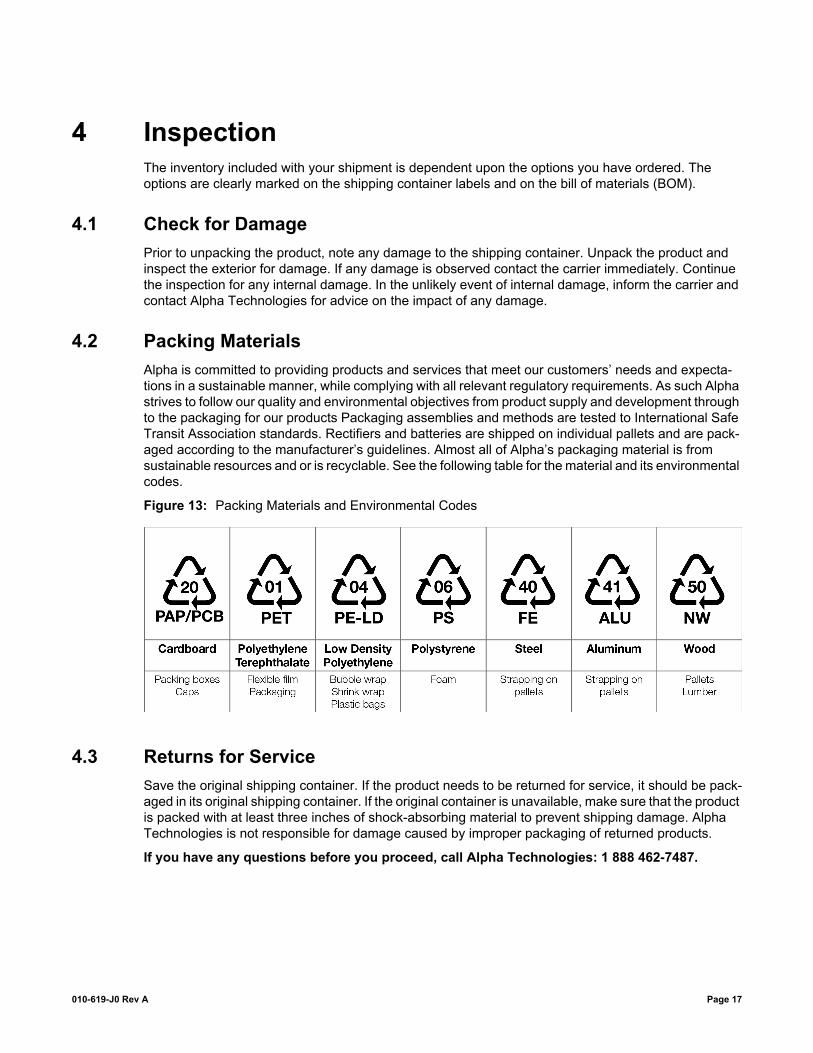
4.2 Packing MaterialsAlpha is committed to providing products and services that meet our customers’ needs and expecta-tions in a sustainable manner, while complying with all relevant regulatory requirements. As such Alpha strives to follow our quality and environmental objectives from product supply and development through to the packaging for our products Packaging assemblies and methods are tested to International Safe Transit Association standards. Rectifiers and batteries are shipped on individual pallets and are pack-aged according to the manufacturer’s guidelines. Almost all of Alpha’s packaging material is from sustainable resources and or is recyclable. See the following table for the material and its environmental codes.
Figure 13: Packing Materials and Environmental Codes
4.3 Returns for ServiceSave the original shipping container. If the product needs to be returned for service, it should be pack-aged in its original shipping container. If the original container is unavailable, make sure that the product is packed with at least three inches of shock-absorbing material to prevent shipping damage. Alpha Technologies is not responsible for damage caused by improper packaging of returned products.
If you have any questions before you proceed, call Alpha Technologies: 1 888 462-7487.
010-619-J0 Rev A Page 17

010-619-J0 Rev A Page 18

5 InstallationNOTE: This power system is suitable for installation in Network Telecommunication Facility locations where the NEC applies, and in OSP applications.
This chapter is provided for qualified personnel to install the product. Mount the unit horizontally in a clean and dry environment.
NOTE: Drawings are located at the rear of the manual.
This system is designed to be installed in a restricted access location that is inaccessible to the general public.
5.1 Safety PrecautionsWARNING: Hazardous voltages are present at the input of power systems. The DC output from the recti-fiers and battery system, though not dangerous in voltage, has a high short circuit current capacity that may cause severe burns and electrical arcing.
Before working with any live battery or power system/distribution center, follow these precautions:
• Remove all metallic jewelry; e.g., watches, rings, metal rimmed glasses, necklaces.
• Wear safety glasses with side shields (and prescription lenses if necessary) at all times during installation.
• Use insulated hand tools.
The installer should follow all applicable local rules and regulations for electrical and battery installa-tions; e.g., CSA, UL, CEC, NEC, OSHA, and local fire codes.
5.2 Shelf Preparation/MountingNOTE: The shelf is designed for horizontal mounting in a clean and dry environment. Allow at least 1.75" of free space in front of the unit for unrestricted cooling airflow.
Each shelf has been designed for center mounting in a 19" or 23" rack (or flush mount for 1RU shelves). See drawings at the end of this manual.
Mounting brackets accommodate either 1" or 1¾" rack spacing. Mount the shelf to the rack using at least two #12 – 24 x ½" screws in each bracket. Use Phillips-type screws and screwdriver to eliminate the possibility of slippage and scratching of the unit’s exterior.
An electrical conducting path must exist between the unit’s chassis and the metalwork of the enclosure in which it is mounted or a grounding conductor. The electrical continuity requirement can be met by the use of thread-forming type unit mounting screws and star washers that remove any paint or non-conductive coatings and establish metal-to-metal contact.
5.3 Module Insertion/RemovalThe rectifier is plug and play. When a rectifier module is added to the system, the controller will detect and update the inventory automatically. Replacing an installed rectifier requires a manual Inventory Update at the controller to clear the removed rectifier from its current list of rectifiers.
010-619-J0 Rev A Page 19
Insert rectifiers by placing the module on the shelf bottom and sliding the module into the rear connector (inside of the shelf). Apply pressure on the front of the module to engage the rear connector in the shelf receptacle. A locking clip is provided to secure the rectifier into the shelf.
NOTE: Do not force a module into position if it does not seat properly. All modules are keyed to ensure that the correct module (polarity/voltage) type is used.
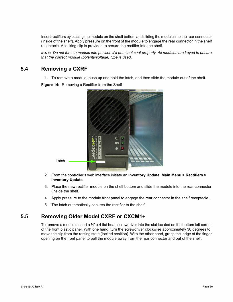
5.4 Removing a CXRF1. To remove a module, push up and hold the latch, and then slide the module out of the shelf.
Figure 14: Removing a Rectifier from the Shelf
2. From the controller’s web interface initiate an Inventory Update: Main Menu > Rectifiers > Inventory Update.
3. Place the new rectifier module on the shelf bottom and slide the module into the rear connector (inside the shelf).
4. Apply pressure to the module front panel to engage the rear connector in the shelf receptacle.
5. The latch automatically secures the rectifier to the shelf.
5.5 Removing Older Model CXRF or CXCM1+To remove a module, insert a ⅛" x 4 flat head screwdriver into the slot located on the bottom left corner of the front plastic panel. With one hand, turn the screwdriver clockwise approximately 30 degrees to move the clip from the resting state (locked position). With the other hand, grasp the ledge of the finger opening on the front panel to pull the module away from the rear connector and out of the shelf.
Latch
010-619-J0 Rev A Page 20

Figure 15: Removing a CXRF or CXCM1 or CXCM1+
5.6 Removing the CXCM1 HPTo remove the CXCM1 HP:
1. Push up and hold the latch while removing the controller.
2. Pull from the location noted in the following image to remove the controller.
CAUTION: When removing the controller in a live system that has an LVD, ensure that the LVD override jumper is set to correct position to avoid possible service disruption. Refer to the wiring and connections section of the manual and the connection drawings
010-619-J0 Rev A Page 21

Figure 16: Removing the CXCM1 HP
1. Push up here and holdto release latch while removingthe controller from the shelf.
2. Pull here to removethe controller from the shelf.
010-619-J0 Rev A Page 22

6 Wiring and ConnectionsThis chapter provides cabling details and notes on cable sizing for DC applications with respect to the shelf.
NOTE: Refer to the drawings located at the rear of the manual.
6.1 Safety PrecautionsWARNING: Hazardous AC voltages may be present. Ensure power at the AC service panel is off before attempting work on the AC connections. Use a voltmeter to verify the absence of voltage. Clearly mark the correct polarity of the battery leads before commencing work on DC connections.
Refer to the chapter on Installation for additional safety precautions.
6.2 Tools RequiredVarious tools are essential for product installation. Insulated tools are recommended. Use this list as a guide:
• Slot head screwdrivers (blade sizes: 1/4", 1/8", 1/16")
• Phillips head screwdriver, #2 (tip size 3/16")
• Digital voltmeter equipped with test leads
• Adjustable 24/48Vdc load (optional)
• Cutters and wire strippers
• Crimping tool (optional for large gauge wire)
• Socket and ratchet set (Imperial measure)
• Anti-static wrist strap
• Computer (laptop) with web browser
• Crossover cable RJ-45 (for access using the Ethernet port)
6.3 AC Feeder Protection/SizingTo maximize system reliability, the AC feed divides the rectifiers into groups to be supplied by separate feeds. See customer connections drawing (modules are numbered left to right).
• 030-834-20: TBA-1 feeds modules 1 and 2. TBA-2 feeds modules 3 and 4.
• 030-835-20: TBA-1 feeds modules 1 and 2. TBA-2 feeds modules 3 and 4.
• 030-845-20: TBA-1 feeds module 1. TBA-2 feeds modules 2 and 3. TBA-3 feeds modules 4 and 5.
• 030-851-20: TBA-1 feeds modules 1 and 2. TBA-2 feeds module 3.
It is recommended, for each feed, to use a dedicated protection feeder breaker located at the AC distri-bution panel. The feeder breaker can also act as the disconnect device for the connected modules.
010-619-J0 Rev A Page 23

An external surge protection device is not required. The rectifiers are protected by internal MOVs.
6.4 AC InputCAUTION: Route the AC input wires in flexible or rigid conduit as far away as possible from the DC power wires to minimize EMI disturbances.
All shelf systems have male IEC-60320-C20 ISA line cord connection points for pluggable line cords with C19R female receptacles.
Refer to customer connection drawings at the rear of this manual.
NOTE: The shelf incorporates IEC plug connections requiring line cords with C19R type receptacles.
Figure 17: (4800W system) AC input, CAN, and signal connections
6.4.1 Strain ReliefCable strain relief for AC cords ship loose in the box with the rectifier shelf.
Push the barbed end of the strain relief into a square hole on the back of the shelf, and then secure the cable with the twist tie.
Table 2: Recommended AC Supply Configuration
AC Input (Vac)Number of Rectifiers on AC
FeedCircuit Breaker, Exact Value
to Use (A)
120/240 1 15
120 2 15
208/220/240 2 20
010-619-J0 Rev A Page 24

Figure 18: AC Cord Strain Relief
6.5 Calculating Output Wire Size RequirementsWire size is calculated by first determining the appropriate maximum voltage drop requirement. Using the formula below calculate the CMA wire size requirement. Determine the size and number of conduc-tors required to satisfy the CMA requirement.
CMA = (A x LF x K) / AVD, where:
• CMA: Cross section of wire in circular MIL area
• A: Ultimate drain in amps
• LF: Conductor loop feet
• K: 11.1 constant factor for commercial (TW type) copper wire
• AVD: Allowable voltage drop
Check again that the ampacity rating of the cable meets the requirement for the installation application. Consult local electrical codes (NEC, CEC, etc.) for guidelines. If required, increase the size of the cable to meet the code.
6.6 DC Output
6.6.1 DC Output for Model 030-851-20 (maximum 3600W)
Chassis and Site Ground ConnectionsWARNING: For safety reasons, ensure the system is properly bonded to the building’s ground grid.
NOTE: This power system is suitable for installation as part of a Common Bonding Network (CBN) and is intended to be used in a DC-C configuration (common DC return). In this configuration, both the shelf chassis ground (via power system chassis ground) and common return shall be connected to the building master ground bus (MGB) or floor ground bus (FGB), in a larger building, to ensure correct operation of the system and to prevent drifting floating analog (especially current) readings.
The chassis is connected to the MGB via mounting brackets.
DC Output to LoadsDC output connections are made at the distribution module at the front of the shelf.
010-619-J0 Rev A Page 25
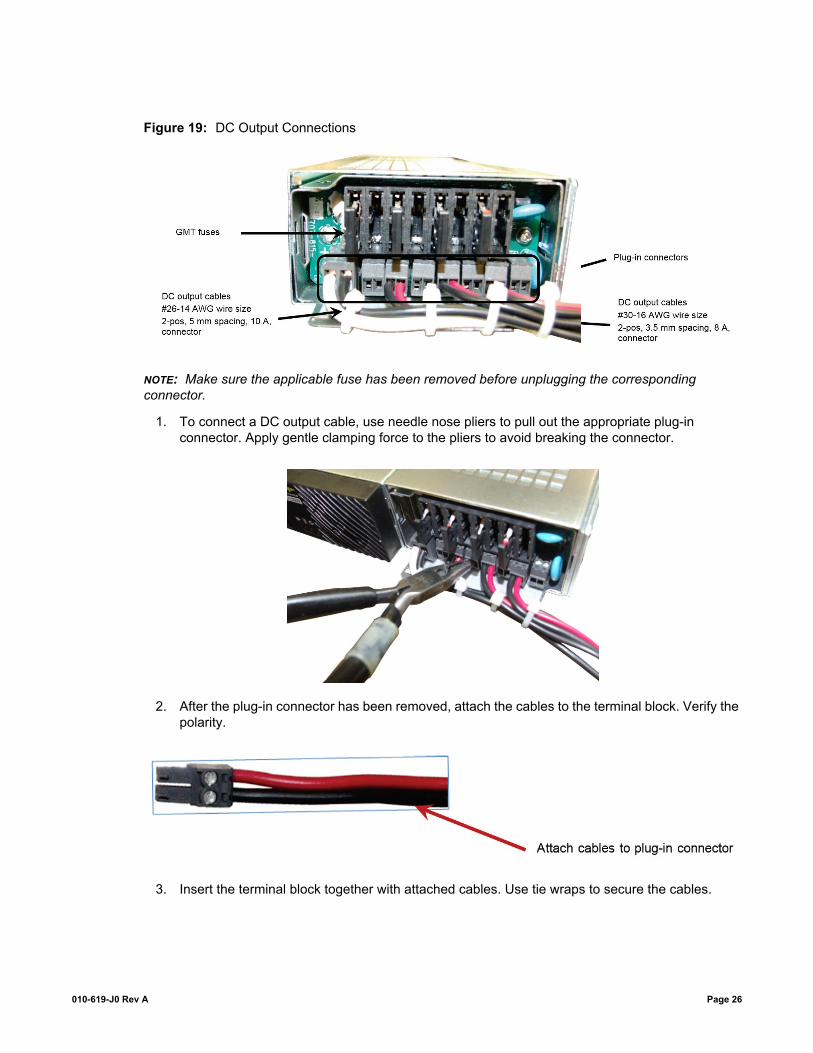
Figure 19: DC Output Connections
NOTE: Make sure the applicable fuse has been removed before unplugging the corresponding connector.
1. To connect a DC output cable, use needle nose pliers to pull out the appropriate plug-in connector. Apply gentle clamping force to the pliers to avoid breaking the connector.
2. After the plug-in connector has been removed, attach the cables to the terminal block. Verify the polarity.
3. Insert the terminal block together with attached cables. Use tie wraps to secure the cables.
010-619-J0 Rev A Page 26
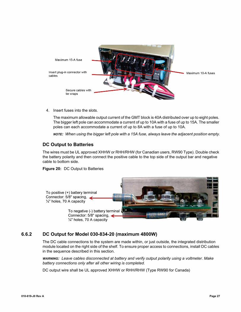
4. Insert fuses into the slots.
The maximum allowable output current of the GMT block is 40A distributed over up to eight poles. The bigger left pole can accommodate a current of up to 10A with a fuse of up to 15A. The smaller poles can each accommodate a current of up to 8A with a fuse of up to 10A.
NOTE: When using the bigger left pole with a 15A fuse, always leave the adjacent position empty.
DC Output to BatteriesThe wires must be UL approved XHHW or RHH/RHW (for Canadian users, RW90 Type). Double check the battery polarity and then connect the positive cable to the top side of the output bar and negative cable to bottom side.
Figure 20: DC Output to Batteries
6.6.2 DC Output for Model 030-834-20 (maximum 4800W)The DC cable connections to the system are made within, or just outside, the integrated distribution module located on the right side of the shelf. To ensure proper access to connections, install DC cables in the sequence described in this section.
WARNING: Leave cables disconnected at battery and verify output polarity using a voltmeter. Make battery connections only after all other wiring is completed.
DC output wire shall be UL approved XHHW or RHH/RHW (Type RW90 for Canada)
010-619-J0 Rev A Page 27

Figure 21: DC Output Connections
NOTE: Cabling must be done with enough slack to allow the distribution assembly to be locked into place.
Chassis and Site Ground ConnectionsWARNING: For safety reasons, ensure the system is properly bonded to the building’s ground grid.
This power system is suitable for installation as part of a Common Bonding Network (CBN), and is intended to be used in a DC-C configuration (common DC return). In this configuration, both the shelf chassis ground (via power system chassis ground) and common return shall be connected to the building master ground bus (MGB) or floor ground bus (FGB), in a larger building, to ensure correct operation of the system and to prevent drifting floating analog (especially current) readings.
The chassis ground connection is located on the center mount rack bracket. Connect to the #10-32 stud using single-hole lug and hardware as provided.
The system MGB connection is located within the distribution module to the left of the chassis ground location. The two studs are oriented at a 45-degree angle, which requires a 1/4" on 5/8" center lug.
Battery ConnectionsThere are connection points for two strings of batteries. Use the thumbscrew lock to disengage part of the distribution assembly and slide it out the right side of the shelf as far as necessary.
Connect the battery (+) cabling to the bottom set of studs and the battery (–) cabling to the upper set. Lugs required are 1/4" on 5/8" centers.
Breaker Return ConnectionsThe load breaker returns (+) for each of the four breakers are also found on the same part of the (sliding) distribution assembly.
Connect to the breaker (ground) returns using 1/4" on 5/8" center lugs.
010-619-J0 Rev A Page 28

Slide the connection point assembly back into the distribution module and secure with the thumbscrew lock. Note the cable(s) and the connection points positioned for proper access.
Figure 22: Breaker Return Connections
Breaker Hot ConnectionsConnect to the four load breaker hot (–) termination pairs using 1/4" on 5/8" center lugs. Connection method is similar for breaker distributions in a 2 load/2 battery CB configuration. Refer to the connection drawing.
Figure 23: Front View of Distribution Module (Cover Removed)
GMT Fuse DistributionTotal current maximum is 30A.
010-619-J0 Rev A Page 29

The ten (10) GMT-style fuses and the associated control terminal blocks are accessible from the front panel of the distribution module (Drawing 030-834-05).
Connect via screw terminations, hot (–) and return (+), for each fuse position.
The maximum allowable output current of the GMT box is 30A distributed over some or all of the ten GMT fuse positions. The largest current that can be accommodated is 10A with a fuse of up to 15A.
If using a 15 A fuse, leave the adjacent fuse position(s) empty.
6.6.3 DC Output for Model 030-835-20/ 030-845-20 (bulk distribution)Models 030-835-20 and 030-845-20 have no integrated distribution. Output connections are made using 1/4" on 5/8" center 2-hole lugs that connect to the main output bars similar to the 030-851-20 battery terminations.
6.7 CAN PortsThe 3 and 4-module shelf, 1RU model with CXCM1+ or CXCM1 HP, has a single CAN port for commu-nications with CAN-enabled equipment (nodes). It is located on the side of the shelf. The 5-module shelf has two ports, one on each side. The 2RU shelf has two ports on the side.
Daisy-chain from node to node (CAN OUT of one node to CAN IN of another) as necessary and ensure that only the last node is terminated.
• 4-module shelf – termination IN – default
• 5-module shelf – termination OUT – default
NOTE: This system has a limit of twelve Cordex 1.2kW rectifiers; due to available power from CAN Bus. They do not have self-powered CAN Bus nodes.
6.8 Network Connection and Remote Communications via CXCAlpha’s Cordex rectifer shelf systems can be set up, monitored and tested via modem or Ethernet 10/100 Base-T serial data connection. The communication protocol supports a web interface. Some standard scenarios are described in the following sections.
6.8.1 Ethernet Port for Network ConnectionThe Ethernet port is designed for CXC connection to a user supplied network (TCP/IP secured by user) via a front panel RJ-45 jack.
Connect to the CXC using a standard network cable. Pinouts are shown in the connection drawings.
6.8.2 Ethernet Port for Local ConnectionLocal access (e.g. laptop computer) is also possible from the Ethernet port connection using a standard network cable.
NOTE: Older CXCM1+ models must use a crossover Ethernet cable for direct connection to a computer.
6.9 Signal Wiring ConnectionsFor terminal block connections, the recommended wire sizes are #16 to #26 AWG (1.5 to 0.129mm2). Control and sense wires shall be UL approved Style 1015 (for Canadian users, TEW type).
010-619-J0 Rev A Page 30
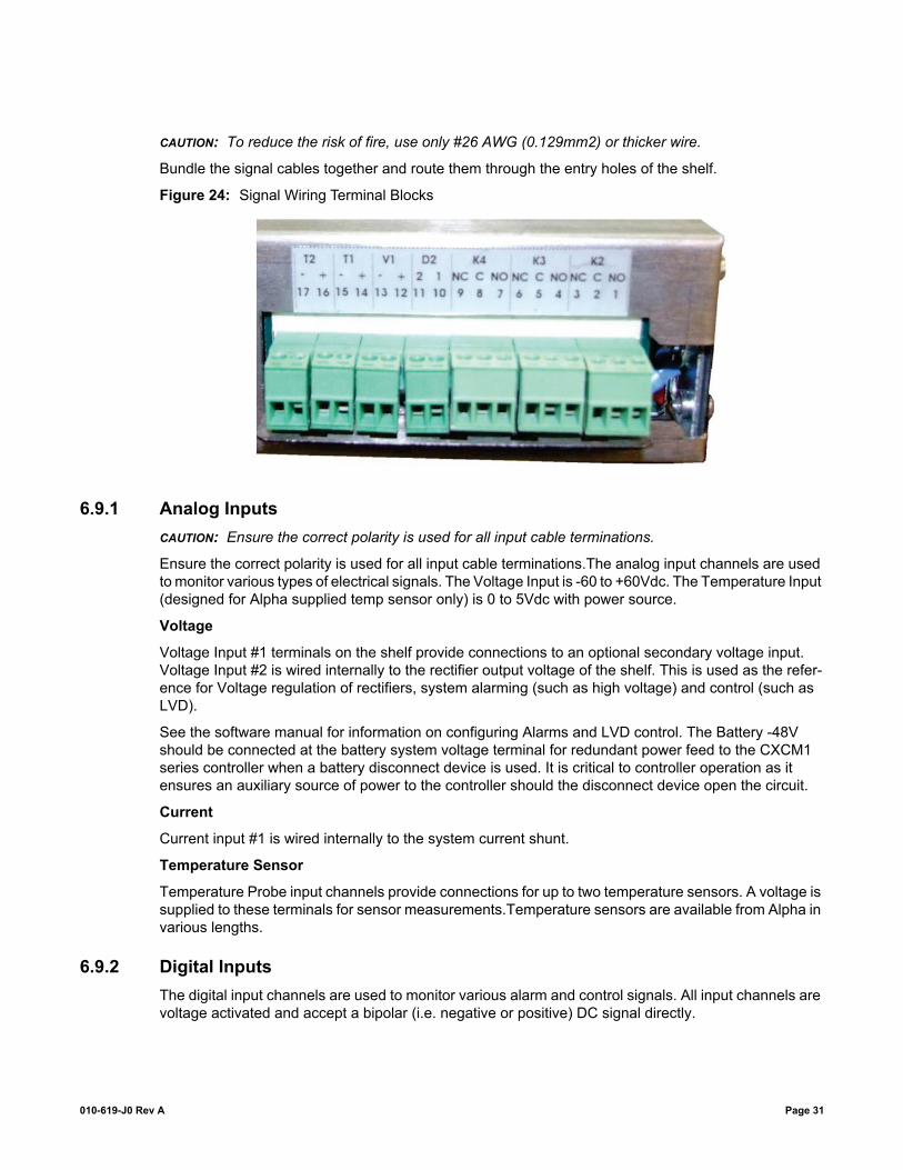
CAUTION: To reduce the risk of fire, use only #26 AWG (0.129mm2) or thicker wire.
Bundle the signal cables together and route them through the entry holes of the shelf.
Figure 24: Signal Wiring Terminal Blocks
6.9.1 Analog InputsCAUTION: Ensure the correct polarity is used for all input cable terminations.
Ensure the correct polarity is used for all input cable terminations.The analog input channels are used to monitor various types of electrical signals. The Voltage Input is -60 to +60Vdc. The Temperature Input (designed for Alpha supplied temp sensor only) is 0 to 5Vdc with power source.
Voltage
Voltage Input #1 terminals on the shelf provide connections to an optional secondary voltage input. Voltage Input #2 is wired internally to the rectifier output voltage of the shelf. This is used as the refer-ence for Voltage regulation of rectifiers, system alarming (such as high voltage) and control (such as LVD).
See the software manual for information on configuring Alarms and LVD control. The Battery -48V should be connected at the battery system voltage terminal for redundant power feed to the CXCM1 series controller when a battery disconnect device is used. It is critical to controller operation as it ensures an auxiliary source of power to the controller should the disconnect device open the circuit.
Current
Current input #1 is wired internally to the system current shunt.
Temperature Sensor
Temperature Probe input channels provide connections for up to two temperature sensors. A voltage is supplied to these terminals for sensor measurements.Temperature sensors are available from Alpha in various lengths.
6.9.2 Digital InputsThe digital input channels are used to monitor various alarm and control signals. All input channels are voltage activated and accept a bipolar (i.e. negative or positive) DC signal directly.
010-619-J0 Rev A Page 31
For shelf modules with integrated distribution, D1 is wired internally for CB/fuse trip. D2 is available for customer connections as required.
Connection Method
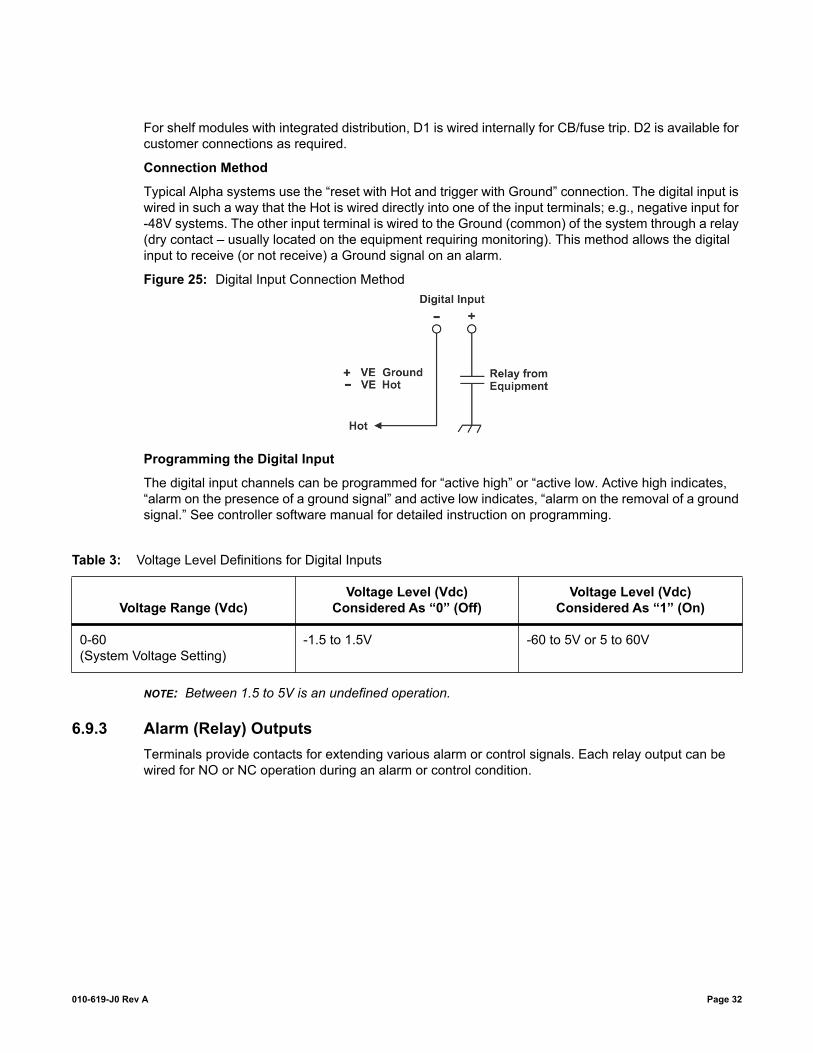
Typical Alpha systems use the “reset with Hot and trigger with Ground” connection. The digital input is wired in such a way that the Hot is wired directly into one of the input terminals; e.g., negative input for -48V systems. The other input terminal is wired to the Ground (common) of the system through a relay (dry contact – usually located on the equipment requiring monitoring). This method allows the digital input to receive (or not receive) a Ground signal on an alarm.
Figure 25: Digital Input Connection Method
Programming the Digital Input
The digital input channels can be programmed for “active high” or “active low. Active high indicates, “alarm on the presence of a ground signal” and active low indicates, “alarm on the removal of a ground signal.” See controller software manual for detailed instruction on programming.
NOTE: Between 1.5 to 5V is an undefined operation.
6.9.3 Alarm (Relay) OutputsTerminals provide contacts for extending various alarm or control signals. Each relay output can be wired for NO or NC operation during an alarm or control condition.
Table 3: Voltage Level Definitions for Digital Inputs
Voltage Range (Vdc)Voltage Level (Vdc)
Considered As “0” (Off)Voltage Level (Vdc)
Considered As “1” (On)
0-60(System Voltage Setting)
-1.5 to 1.5V -60 to 5V or 5 to 60V
010-619-J0 Rev A Page 32

Figure 26: Relay Connections
Relays can be programmed to energize or de-energize during an alarm condition (see CXC Software manual). When the CXCM1+ reset button is pressed or power is lost, all relays de-energize.
These relays could be used for additional external LVD contactor control; however, this would not provide the redundant LVD control as with the assigned output pins described below.
6.9.4 LVD Control (Load Disconnect or Battery Disconnect)The disconnect option is controlled by and connected internally to relay K1.
LVD Inhibit
Should it be necessary to remove a CXCM1 series controller, the customer connection board (on the front of the shelf) provides shorting pins (JP2) to inhibit (or override) the LVD Control function. See the connections drawings.
If the LVD is controlled on NC contacts (factory default for LVD option), then JP2 pins 1 and 2 must be shorted together to maintain LVD operation. If the LVD is controlled on NO contacts, then pins 2 and 3 must be shorted together. For normal operation, the factory-supplied shorting jumper should be left on pins 3 and 4.
6.9.5 LVD Control AlternativeThe LVD Control functions can be hardwired directly from an alarm output relay to an external LVD contactor (or panel). See Controls Menu Defaults in the CXC Software manual.
010-619-J0 Rev A Page 33

010-619-J0 Rev A Page 34

7 Operation
7.1 Main Rectifier StatesRectifier operation has five main states; each state is distinct and necessary for the operation of the rectifier.
• Off
• Start Delay
• Soft Start
• Normal Operation
• Turning Off
7.1.1 OffThe rectifier is in the Off state immediately after power is applied to the rectifier or after a rectifier shut-down (remote or local shutdown, AC shutdown, OVP or thermal shutdown).
In this state the DC-DC converter is turned off and the CXC monitors its inputs for the proper conditions to begin the start up sequence.
When the conditions have been met for the rectifier to start up, it transitions to the Start Delay state.
7.1.2 Start DelayWhen the rectifier is in the Start Delay state, the DC-DC converter is held off and still not sourcing power, waiting for a given amount of time before transitioning to the next state.
The CXC continues to monitor its inputs.
After the Start Delay state the rectifier transitions to the Soft Start state.
NOTE: Soft start, or current walk-in, gradually increases the voltage and current output of the rectifier upon startup. This is done to reduce the instantaneous load on the AC source.
7.1.3 Soft StartWhen the Soft Start state is entered, the rectifier is turned on and the output voltage and output current gradually increased. If a load is present, the rectifier begins to source power.
When the voltage and current limit ramps have finished, the rectifier will transition to the Normal Oper-ation state.
7.1.4 Normal OperationThe Normal Operation state is the state that the rectifier will be in performing all of the rectifier functions and features specified herein.
From this state, the only valid transition is to the Turning Off state. This transition will happen if the recti-fier is required to shut down.
010-619-J0 Rev A Page 35
7.1.5 Turning OffThe Turning Off state is entered because a short delay is required before the rectifier actually turns off to take care of any initialization requirements.
When this short delay has elapsed, a transition to the Off state is made.
7.2 Main Rectifier ModesIn addition to main rectifier states, there is a set of main rectifier modes. These modes are divided into two categories:
7.2.1 Output Voltage ModesVoltage modes, under software control, can directly adjust the output voltage. Situations, such as the rectifier being in current limit, can change the output voltage with no software control.
The following table describes the five output voltage modes.
7.2.2 Output Current/Power ModesThese four output current/power modes directly affect the output current and power:
Table 4: Output Voltage Modes
Output Voltage Modes Active when...
Float Output voltage is set to the float voltage setting.
Equalize Output voltage is set to the equalize voltage setting.
Battery Test Output voltage is set to the battery test voltage setting.
Safe Output voltage is set to the safe mode voltage setting.
Manual Test Output voltage can be manually adjusted outside of the standard adjustment ranges.
Table 5: Output Current/Power Modes (Sheet 1 of 2)
Output Current/Power Mode Output current and power limit have been reduced due to:
Temperature foldback mode
High temperature of the heatsink or internal ambient temperature sensor.
AC foldback mode Low AC input voltage.
NOTE: Reduces the risk of tripping an AC breaker due to increased AC current draw as the AC voltage decreases.
010-619-J0 Rev A Page 36

7.3 Can Bus CommunicationThe CAN bus is used for commands and data transfer between the rectifier and controller to configure the rectifier with system settings and to monitor rectifier status.
7.4 Factory Ranges and DefaultsThe following table lists the rectifier settings/ranges/defaults; changes are made from the CXC:
Short circuit foldback mode
Short circuit at the output.
Internal fault foldback mode
Internal fault.
Table 5: Output Current/Power Modes (Continued) (Sheet 2 of 2)
Output Current/Power Mode Output current and power limit have been reduced due to:
Table 6: Factory Ranges and Defaults (Sheet 1 of 2)
Setting Range (minimum to maximum) Default
Float (FL) Voltage 48 – 58V 54V
Equalize (EQ) Voltage 50 – 58V 55V
Battery Test (BT) Voltage 44 – 52V 46V
OVP See note below – 59V 57V
Current Limit (CL) 23 – 100% 100%
Power Limit (PL) 0 – 100% 100%
Module Start Delay 0 – 250s 1s
System Start Delay 0 – 600s 0s
Low Voltage Alarm (LVA) 42 – 52V 44V
High Voltage Alarm (HVA) 52 – 59V 55.5V
EQ Timeout 1 – 2399h 30h
BT Timeout 1 – 250h 8h
Softstart Ramp-rate Normal/Fast Normal
010-619-J0 Rev A Page 37

NOTE: OVP cannot be set below the present system/FL/EQ/BT voltage setting or the safe mode voltage of 51.4V.
CL/PL Alarm Enable/Disable Enable
Remote Shutdown Enable/Disable Enable
Ramp Test Enable/Disable Enable
Table 6: Factory Ranges and Defaults (Continued) (Sheet 2 of 2)
Setting Range (minimum to maximum) Default
010-619-J0 Rev A Page 38

8 System Startup
8.1 Check System Connections• Ensure AC is off, battery is disconnected, and all power modules are removed from the shelf.
• Triple-check the polarity of all connections.
8.2 Verify AC and Power The Shelf• Install one power module.
• Verify AC input voltage is correct and turn on the corresponding AC input feeder breaker.
• The power module OK LED should illuminate after a preset start delay.
• Using the CXC, test functionality of various module alarms and controls.
8.3 Check Battery Polarity and Connect• Verify correct battery polarity using a voltmeter (ensuring no cells or batteries are reversed).
• Connect battery as required to the output of the system or turn on battery breaker.
• Install remaining power modules.
• On the CXC, set Float and Equalize voltage to the levels specified by the battery manufacturer.
• For some systems, the default setting for low AC voltage alarming is 180Vac. For nominal 120Vac operation, it is recommended to reset this value to 100Vac.
• Using the CXC, test the functionality of various module alarms and controls. In addition, perform a load test with the system using a resistive load box as needed.
8.4 Controller Reset
8.4.1 Soft Reset (CXCM1+ only)The reset button located on the front panel of the CXCM1+ is for restarting the microprocessor. When pressed momentarily, the unit beeps twice then resets. The front-panel LEDs illuminate temporarily, and then extinguish after the system has finished its 15-second self-test.
NOTE: This does not apply to the CXCM1 HP.
8.4.2 IP Address Reset (CXCM1+ only)To reset the IP address, press and hold the front panel reset button for three seconds. The CXCM1+ unit beeps three times, IP address resets to 10.10.10.201 and DHCP is disabled. The settings are saved and the unit then resets.
This reset allows local access; e.g., with a laptop and a standard network crossover cable. See current version software manual for details.
NOTE: This does not apply to the CXCM1 HP.
010-619-J0 Rev A Page 39

8.4.3 Hard ResetA hard reset of the controller can be performed by unplugging the module. This procedure will restart the microprocessor if the front panel (soft) reset button fails to operate.
CAUTION: Move the LVD control jumper to the override position before unplugging the controller. The load and batteries are still connected. Use of hard reset may cause loss of data.
8.5 Accessing the LVD JumperTo change the LVD control jumper position:
1. Remove the GMT fuse cover by gently squeezing the sides of the cover. The cover will unlatch and pop off.
2. Use pliers to gently move the LVD control jumper from the auto position to the override position.
010-619-J0 Rev A Page 40

9 MaintenanceAlthough very little maintenance is required with Alpha systems, routine checks and adjustments are recommended to ensure optimum system performance. Qualified service personnel should do repairs.
The following table lists a few maintenance procedures for this system. These procedures should be performed at least once a year.
In areas where flying insects and other debris may routinely clog the rectifier fan filter, it may be neces-sary to inspect ventilation openings and replace the rectifier fan filter more often.
WARNING: HIGH VOLTAGE AND SHOCK HAZARD.
Use extreme care when working inside the shelf while the system is energized. Do not make contact with live components or parts.
IMPORTANT: Circuit cards can be damaged by static electricity. Always wear a grounded wrist strap when handling or installing circuit cards.
9.1 Rectifier Fan Replacement
Rectifier modules can be removed and re-inserted with the power on.
The fan replacement kit part number is 010-619-G0-000.
Figure 27: Rectifier Fan Replacement
NOTE: This procedure takes about 5 minutes to complete.
Table 7: Sample Maintenance Log
Procedure Date Completed
Clean ventilation openings (replace rectifier fan filter if necessary)
Inspect all system connections (re-torque as necessary)
Verify alarm/control settings
Verify alarm relay operation
010-619-J0 Rev A Page 41

1. Slide the module 10 cm (4") out of the shelf and wait two minutes for module capacitors to discharge.
2. Remove the bottom screw that secures the front panel to the module chassis
3. Slide the front panel out.
4. Disconnect the fan power lead wires from the module.
5. Note the direction of airflow and remove the fan from the front panel.
6. Install the replacement fan following the preceding steps in reverse order.
9.2 Rectifier Fan Filter Replacement
Rectifier modules can be removed and re-inserted with the power on.
The fan filter part number is 747-581-20-060.
Figure 28: Rectifier Fan Filter Replacement
NOTE: This procedure takes about 5 minutes to complete.
1. Slide the module 10 cm (4") out of the shelf and wait two minutes for module capacitors to discharge.
2. Remove the bottom screw that secures the front panel to the module chassis
3. Slide the front panel out.
4. Remove the screen and replace the filter. Replace the screen.
5. Replace the front panel and secure with the screw removed in Step 2.
010-619-J0 Rev A Page 42

9.3 Removing the CXCM1 HPFigure 29: Removing the CXCM1 HP
1. Push up here and holdto release latch while removingthe controller from the shelf.
2. Pull here to removethe controller from the shelf.
010-619-J0 Rev A Page 43

010-619-J0 Rev A Page 44

10 Warranty and Service Information
10.1 Technical SupportIn Canada and the USA, call toll free 1-888-462-7487.
Customers outside Canada and the USA, call +1-604-436-5547.
10.2 Warranty StatementFor full information details review Alpha's online Warranty Statement at www.alpha.ca.
10.3 Product WarrantyAlpha warrants that for a period of two (2) years from the date of shipment its products shall be free from defects under normal authorized use consistent with the product specifications and Alpha’s instructions, the terms of the manual will take precedence.The warranty provides for repairing, replacing or issuing credit (at Alpha’s discretion) for any equipment manufactured by it and returned by the customer to the factory or other authorized location during the warranty period. There are limitations to this warranty coverage. The warranty does not provide to the customer or other parties any remedies other than the above. It does not provide coverage for any loss of profits, loss of use, costs for removal or installation of defective equipment, damages or consequential damages based upon equipment failure during or after the warranty period. No other obligations are expressed or implied. Warranty also does not cover damage or equipment failure due to cause(s) external to the unit including, but not limited to, environ-mental conditions, water damage, power surges or any other external influence.The customer is responsible for all shipping and handling charges. Where products are covered under warranty Alpha will pay the cost of shipping the repaired or replacement unit back to the customer.
10.4 Battery WarrantyNote that battery warranty terms and conditions vary by battery and by intended use. Contact your Alpha sales representative or the Technical Support team at the above number to understand your enti-tlements under Battery Warranty.
10.5 Warranty ClaimsAny claim under this Limited Warranty must be made in writing to Alpha BEFORE sending material back. Alpha will provide Product return instructions upon approval of return request. A Service Repair Order (SRO) and / or Return Authorization (RA) number will be issued ensuring that your service needs are handled promptly and efficiently.Claims must be made online at: www.alpha.ca.
10.6 Service InformationFor a list of international service centers, visit: www.alpha.ca.
010-619-J0 Rev A Page 45

010-619-J0 Rev A Page 46

11 CertificationCSA (Canadian Standards Association also known as CSA International) was established in 1919 as an independent testing laboratory in Canada. CSA received its recognition as an NRTL (Nationally Recognized Testing Laboratory) in 1992 from OSHA (Occupational Safety and Health Administration) in the United States of America (Docket No. NRTL-2-92). This was expanded and renewed in 1997, 1999, and 2001. The specific notifications were posted on OSHA’s official website as follows:
• Federal Register #: 59:40602 - 40609 [08/09/1994]
• Federal Register #: 64:60240 - 60241 [11/04/1999]
• Federal Register #: 66:35271 - 35278 [07/03/2001]
When these marks appear with the indicator “C and US” or “NRTL/C” it means that the product is certi-fied for both the US and Canadian markets, to the applicable US and Canadian standards. (1)
Alpha rectifier and power system products, bearing the aforementioned CSA marks, are certified to CSA C22.2 No. 60950-01 and UL 60950-1. Alpha UPS products, bearing the aforementioned CSA marks, are certified to CSA C22.2 No. 107.3 and UL 1778. As part of the reciprocal, US/Canada agreement regarding testing laboratories, the Standards Council of Canada (Canada’s national accreditation body) granted Underwriters Laboratories (UL) authority to certify products for sale in Canada. (2) Only Under-writers Laboratories may grant a license for the use of this mark, which indicates compliance with both Canadian and US requirements.(3)
NRTL’s Capabilities
NRTLs are third party organizations recognized by OSHA, US Department of Labor, under the NRTL program. The testing and certifications are based on product safety standards developed by US based standards developing organizations and are often issued by the American National Standards Institute (ANSI). (4) The NRTL determines that a product meets the requirements of an appropriate consensus-based product safety standard either by successfully testing the product itself, or by veri-fying that a contract laboratory has done so, and the NRTL certifies that the product meets the require-ments of the product safety standard. (4)
Governance of NRTL
The NRTL Program is both national and international in scope with foreign labs permitted.
(1) www.csagroup.org
(2)www.scc.ca
(3)www.ulc.ca
(4)www.osha.gov
010-619-J0 Rev A Page 47

010-619-J0 Rev A Page 48

12 Glossary
ACAlternating Current
ADIOAnalog-digital input-output
ALCOAlarm cutoff
ATMAsynchronous Transfer Mode; e,g. ATM cell
BCTBattery current termination
BODBattery on discharge
BTBattery test (or test mode)
CANController Area Network
CEMFCounter electro-motive force
CXCordex series; e.g. CXC for Cordex™ System Controller
DCDirect current
DODDepth of discharge
EQEqualize (mode or voltage)
FLFloat (mode or voltage)
GUIGraphical User Interface
HVAHigh voltage alarm
HVSDHigh voltage shutdown
ICMPInternet control message protocol
IPInternet Protocol
LCDLiquid Crystal Display
LEDLight Emitting Diode
010-619-J0 Rev A Page 49

LVALow voltage alarm
LVCLow voltage connect
LVDLow voltage disconnect
MACMedia Access Control; e.g. MAC address
MIBManagement Information Base
MUXMultiplexer
OCPOver Current Protection
OLEDOrganic LED, in-shelf controller display
OVPOver-voltage protection
PDAPersonal Digital Assistant
PPPPoint to Point Protocol
RASRemote access server
SELVSafety Extra Low Voltage
SCISerial Communication Interface
SNMPSimple Network Management Protocol
TCP/IPTransmission Control Protocol / Internet Protocol
TrapEvent notification
010-619-J0 Rev A Page 50

13 Specifications
13.1 Cordex HP 48 1.2kW Switched Mode Rectifier
Table 8: Specifications: Cordex HP 48 1.2kW, Switched Mode Rectifier (Sheet 1 of 3)
Specifications: Cordex HP 48-1.2kW, Switched Mode Rectifier
Power Module Output
Voltage: 42 to 58Vdc within rated limits
Power: 1200W (176 to 300Vac input) 600W minimum (110 to 130Vac input) [Subject to de-rating below 110Vac due to current limited input and when operated above temperature thresholds listed below]
Current: 22.2A @ 54Vdc, 25A maximum @ 48Vdc (176 to 300Vac input) 11.1A @ 54Vdc, 12.5A maximum @ 48Vdc (110 to 130Vac input)
Static Load Regulation:
Better than ±0.5% for any load change within rated limits
Static Line Regulation: Better than ±0.1% for any change in input voltage within rated limits
Dynamic Line Regulation:
Better than ±1% for any change in input voltage within rated limits (output voltage shall recover to static limits within 2ms)
Hold up Time: >10ms
Time Stability: ≤0.2% per year
Temperature Stability: ≤100ppm/°C over the operating range
Heat Dissipation: <308 BTU per hour (per rectifier module)
Electrical Noise: <38dBrnC (voice band) <30mVrms 10kHz to 10MHz (wide band) <150mVp-p 10kHz to 100MHz <2mV (psophometric)
Acoustic Noise: <60dBa @ 1m (3ft.) @ 30°C (86°F)
EMI: The unit meets requirements of EN55022: Class A for Radiated Emissions, and Class B for Conducted Emissions (see Standards for more EMC)
In accordance with FCC requirements, we provide the following statement as specified in the FCC guidelines for conformance to Part 15, Class A:
010-619-J0 Rev A Page 51

NOTE: This equipment has been tested and found to comply with the limits for a Class A digital device, pursuant to part 15 of the FCC Rules. These limits are designed to provide reasonable protection against harmful interference when the equipment is operated in a commercial environment. This equipment generates, uses, and can radiate radio frequency energy and, if not installed and used in accordance with the instruction manual, may cause harmful interference to radio communications. Operation of this equipment in a residential area is likely to cause harmful interference in which case the user will be required to correct the interference at his own expense.
Any changes or modifications to this equipment not expressly described in this manual could void the FCC compliance.
Power Module Input
Voltage: 208/220/240Vac (continuous operation 90-300Vac) High: 277 to 300Vac (de-rated power factor) Low: 90 to 176Vac (de-rated output power)
Frequency: 50/60Hz nominal (45 to 66Hz)
Current: 7.5A maximum (176 to 300Vac) 6A maximum (90 to 176Vac)
Power Factor: >0.99 at nominal conditions and 50-100% load
Protection: 10kA-interrupting capacity fuses in active and neutral lines
Efficiency: >94% peak; 93.5% at nominal conditions and 50-100% load
Inrush current: ≤ full load steady state current of the rectifier within rated limits
Start-up Ready Time: <5 seconds (excluding soft start) to complete inrush limit routine and ac measurement (for OK signal)
Start-up Delay: Programmable up to 120 seconds to enable stagger-start of multiple rectifiers and to minimize the effect on a supply source
Soft Start: User adjustable to at least 5 seconds (not including start-up delay time) and is determined by output current limit ramp-up
T.H.D. (Current): <5% at 100% load for 208 to 220Vac
Input Transient Suppression:
Meets ANSI/IEEE C62.41 Category B3
Input Leakage Current: <3.5mA @ 265Vac 60Hz for up to two rectifiers* >5mA @ 265Vac 60Hz for three or more rectifiers* [*plugged inside 1RU or 2RU shelf] See Warning note at the end of Important Safety Instructions page
Environmental
Table 8: Specifications: Cordex HP 48 1.2kW, Switched Mode Rectifier (Continued) (Sheet 2 of 3)
Specifications: Cordex HP 48-1.2kW, Switched Mode Rectifier
010-619-J0 Rev A Page 52

The above information is valid at the time of publication. Consult factory for up-to-date ordering infor-mation. Specifications are subject to change without notice.
Operating Temperature:
-40 to +65°C (-40 to 149°F) -40 to +80°C (-40 to 176°F) [de-rated output power]
Storage Temperature: -40 to +80°C (-40 to 176°F)
Humidity: 0 to 95% RH non-condensing
Elevation: -500 to +2800m; to 4000m with temperature de-rated to 40°C (-1640 feet to 9186 feet; to 13124 feet with temperature de-rated to 104°F)
Mechanical
MTBF: 222,469 hours ground benign @ 25°C (77°F)
Dimensions: 44mm H x 88mm W x 318mm D [1.73" H x 3.5" W x 12.5" D]
Weight: 1.23 kg (2.72 lb.)
Compliance
EN 55022 (CISPR 22): Information Technology Equipment – Radio Disturbance Characteristics – Limits and Methods of Measurement, Class A and Class B
EN 61000-3-2: Harmonic Current Emissions
EN 61000-3-3: Voltage Fluctuations and Flicker
EN 61000-4-2: ESD Immunity
EN 61000-4-3: Radiated Electromagnetic Immunity
EN 61000-4-4: Electrical Fast Transient/Burst Immunity
EN 61000-4-5: Power Line Surge Immunity
EN 61000-4-6: Conducted Electromagnetic Immunity
EN 61000-4-11 Voltage Dips, Short Interruptions and Variations
GR-63-CORE: Physical Protection
GR-1089-CORE: Electromagnetic Compatibility and Electrical Safety
CE IEC/EN: 60950-1 CB Scheme
Table 8: Specifications: Cordex HP 48 1.2kW, Switched Mode Rectifier (Continued) (Sheet 3 of 3)
Specifications: Cordex HP 48-1.2kW, Switched Mode Rectifier
010-619-J0 Rev A Page 53

13.2 CXCM1 HP Controller
Table 9: Specifications: CXCM1 HP Controller (Sheet 1 of 3)
Specifications: Basic Unit, CXCM1 HP
Input Voltage: 12 to 60Vdc within rated limits
Current: <200mA @ 52Vdc, <400mA @ 26.5Vdc, <800mA @ 13.2Vdc
MTBF: 95,000 hours (10.9 years), with display off OLED 84,000 hours @ 10% usage, 9,800 at100% usage, at 25°C
Safety: CSA 60950-1-03 IEC/EN 60950-1 CE Mark
EMC: The unit meets requirements of: • EN 300 386-2 EMC and EMR, Telecommunications Network Equipment
Emissions: • EN 55022 Class A (CISPR 22)• CFR47 (FCC) Part 15 Class A
Immunity: • EN 61000-4-2 ESD EN 61000-4-3• Radiated EN 61000-4-4 EFT /Burst• EN 61000-4-6 Conducted
Environmental: • ETS 300 019-1-1 Environmental Conditions, Storage• ETS 300 019-1-2 Environmental Conditions, Transportation
NEBS: • GR-63-CORE Physical Protection• GR-1089-CORE Electromagnetic Compatibility and Electrical Safety
In accordance with FCC requirements, we provide the following statement as specified in the FCC guidelines for conformance to Part 15, Class A:
NOTE: This equipment has been tested and found to comply with the limits for a Class A digital device, pursuant to part 15 of the FCC Rules. These limits are designed to provide reasonable protection against harmful interference when the equipment is operated in a commercial environment. This equipment generates, uses, and can radiate radio frequency energy and, if not installed and used in accordance with the instruction manual, may cause harmful interference to radio communications. Operation of this equipment in a residential area is likely to cause harmful interference in which case the user will be required to correct the interference at his own expense.
Any changes or modifications to this equipment not expressly described in this manual could void the FCC compliance.
Environmental
010-619-J0 Rev A Page 54

Temperature: -40 to 75°C (-40 to 167°F) operating -40 to 80°C (-40 to 176°F) storage
Humidity: 5% to 95% RH non-condensing
Elevation: -500 to +4000m (-1640 to 13124 ft)
Hardware: CXCM1 HP
Hardware
CPU: ARM A8
RAM: 128MB
Flash: 256MB
Display: 5-line, LCD matrix
Front Panel Controls:
Menu up and down, home and select buttons
LED’s: System OK (Green) Power System Minor Alarm (Yellow) Power System Major Alarm / Controller Fail (Red)
Audio: Built-in speaker for alarm and popup message tones 70dbl
Dimensions: 44mm H x 88mm W x 318mm D (1.73" H x 3.5" W x 12.5" D)
Weight: 0.62 kg (1.36 lb.)
Mounting: Modular on Cordex CXRF 48-1.2kW series shelves
Relay Outputs: Four (4) Form C, 60Vdc 1A maximum
Digital Inputs: Two (2), ±60Vdc
Analog Inputs: One (1) DC voltage, 0 to 60Vdc, One (1) DC current, compatible with ±25mV to ±200mV shunts, Two (2) temperature, 0 to 5Vdc with power source
Communication Ports:
Ethernet RJ-45, USB 2.0, CAN (see shelf specifications)
Recommended Signal Wire Sizes
Wire Size Range: #16 to #26 AWG (1.5 to 0.14mm2)
Table 9: Specifications: CXCM1 HP Controller (Continued) (Sheet 2 of 3)
Specifications: Basic Unit, CXCM1 HP
010-619-J0 Rev A Page 55

13.3 CXCM1+ Controller
Temperature Rating:
90°C (194°F)
CAUTION: TO REDUCE RISK OF FIRE, USE ONLY #26 AWG (0.14mm2) OR LARGER WIRE.
The above information is valid at the time of publication. Consult factory for up-to-date ordering information. Specifications are subject to change without notice.
Table 9: Specifications: CXCM1 HP Controller (Continued) (Sheet 3 of 3)
Specifications: Basic Unit, CXCM1 HP
Table 10: Specifications: CXCM1+ Controller (Sheet 1 of 3)
Specifications: Basic Unit, CXCM1+
Input Voltage: 17 to 60Vdc within rated limits
Current: <100mA @ 48Vdc <200mA @ 24Vdc
MTBF: 472,000 hours @ 25°C (77°F)
EMC: The unit meets requirements of: Emissions: • EN 55022 Class A (CISPR 22)• CFR47 (FCC) Part 15 Class A
Immunity: • EN 61000-4-2 ESD EN 61000-4-3• Radiated EN 61000-4-4 EFT /Burst• EN 61000-4-6 Conducted
NEBS: • GR-63-CORE Physical Protection• GR-1089-CORE Electromagnetic Compatibility and Electrical Safety
In accordance with FCC requirements, we provide the following statement as specified in the FCC guidelines for conformance to Part 15, Class A:
010-619-J0 Rev A Page 56

NOTE: This equipment has been tested and found to comply with the limits for a Class A digital device, pursuant to part 15 of the FCC Rules. These limits are designed to provide reasonable protection against harmful interference in a residential installation. This equipment generates, uses, and can radiate radio frequency energy and, if not installed and used in accordance with the instructions, may cause harmful interference to radio communications. However, there is no guarantee that interference will not occur in a particular installation. If this equipment does cause harmful interference to radio or television reception, which can be determined by turning the equipment off and on, the user is encour-aged to try to correct the interference by one or more of the following measures:
• Reorient or relocate the receiving antenna.• Increase the separation between the equipment and receiver.• Connect the equipment into an outlet on a circuit different from that to which the receiver is
connected.• Consult the dealer or an experienced radio/TV technician for help.
Any changes or modifications to this equipment not expressly described in this manual could void the FCC compliance.
Environmental
Temperature: -40 to 75°C (-40 to 167°F) operating -40 to 80°C (-40 to 176°F) storage
Humidity: 0 to 95% RH non-condensing
Elevation: -500 to +4000m (-1640 to 13124 ft)
Hardware
CPU: Coldfire
RAM: 8MB
Flash: 4MB standard
Display: 4 digit LCD
Front Panel Controls:
Display pushbutton toggle switch for voltage (V) or current (A) Reset switch (soft reset button; hold for 3 seconds to reset IP)
LED’s: System OK (Green) Power System Minor Alarm (Yellow) Power System Major Alarm / Controller Fail (Red)
Audio: Built-in speaker for alarm and popup message tones
Dimensions: 44mm H x 88mm W x 318mm D (1.73" H x 3.5" W x 12.5" D)
Weight: 0.62 kg (1.36 lb.)
Table 10: Specifications: CXCM1+ Controller (Continued) (Sheet 2 of 3)
Specifications: Basic Unit, CXCM1+
010-619-J0 Rev A Page 57

13.4 2RU, 4.8kW, 4 Module System
Mounting: Modular on Cordex CXRF 48-1.2kW series shelves (options for 1RU horizontal or 2RU vertical orientation depending on shelf)
Relay Outputs: Four (4) Form C, 60Vdc 1A maximum
Digital Inputs: Two (2), 0 to 60Vdc
Analog Inputs: One (1) DC voltage, 0 to 60Vdc One (1) DC current, ±50mV Two (2) temperature, 0 to 20Vdc with power source
Communication Ports:
Ethernet RJ-45, Alpha Modem DB-9, CAN (see shelf specifications)
Recommended Signal Wire Sizes
Wire Size Range: #16 to #26 AWG (1.5 to 0.14mm2)
Temperature Rating:
90°C (194°F)
CAUTION: TO REDUCE RISK OF FIRE, USE ONLY #26 AWG (0.14mm2) OR LARGER WIRE.
The above information is valid at the time of publication. Consult factory for up-to-date ordering information.Specifications are subject to change without notice.
Table 10: Specifications: CXCM1+ Controller (Continued) (Sheet 3 of 3)
Specifications: Basic Unit, CXCM1+
Table 11: Specifications: 48-1.2kW 19”, 2RU, 4.8kW, 4 Module System
Specifications: 48-1.2kW 19”, 2RU, 4.8kW, 4 Module System
Basic Unit: Shelf
Maximum Output: 4.8kW
Recommended Feed Breaker, Single Phase:
120V: 15A, #14 AWG (two modules per feed) 220/240V: 20A, #12 AWG (two modules per feed)
Mechanical
Dimensions: 88mm H x 439.5mm W x 305mm D, rectifier front panel 12.5mm D (3.5" H x 17.3" W x 12" D, rectifier front panel 0.49" D)
Mounting: 19" or 23" rack, 6" offset (center), EIA rack spacing
010-619-J0 Rev A Page 58

13.5 1RU, 4.8kW, 4 Module System with Controller
Weight: 4.55 kg (10.03 lb)
Connections
AC Input (dual): Dual IEC-60320-C20 MAIC connectors (for use with IEC-60320-C19 female line cords)
Chassis ground: #10-32 stud
Communications: CAN (bus, dual in/out) RJ-12 offset (female)
Site ground: 1/4" on 5/8" centers
Battery Output: 1/4" on 5/8" centers, two (2) sets per polarity
Load Output: AM breakers: 1/4" on 5/8" centers GMT fuses: screw terminal #16 to #26 AWG (1.5 to 0.129mm2)
Signal wiring: Terminal blocks #16 to #26 AWG (1.5 to 0.129mm2)
Agency Compliance
UL: 60950-1
CSA: 60950-1
CE IEC/EN: 60950-1, CB Scheme
Telcordia: NEBS certified Level 3 compliant
NOTE: This equipment is suitable for use in “Common Bonding Network” configuration.
* See drawings at the rear of this manual. The above information is valid at the time of publication. Consult factory for up-to-date ordering information. Specifications are subject to change without notice.
Table 11: Specifications: 48-1.2kW 19”, 2RU, 4.8kW, 4 Module System
Specifications: 48-1.2kW 19”, 2RU, 4.8kW, 4 Module System
Table 12: Specifications: 48-1.2kW 19”, 1RU, 4.8kW, 4 Module System
Specifications: 48-1.2kW 19”, 1RU, 4.8kW, 4 Module System
Basic Unit: Shelf
Maximum Output: 4.8kW
010-619-J0 Rev A Page 59

Recommended Feed Breaker, Single Phase:
120V: 15A, #14 AWG (two modules per feed) 220/240V: 20A, #12 AWG (two modules per feed)
Mechanical
Dimensions: 44mm H x 439.5mm W x 305mm D (rectifier front panel 12.5mm D) [1.75" H x 17.3" W x 12" D (rectifier front panel 0.49" D)]
Mounting: 19" or 23" rack, center (5" or 6") or flush, EIA rack spacing
Weight: 3.0 kg (6.6 lb.)
Connections
AC Input (dual): Dual IEC-60320-C20 MAIC connectors (for use with IEC-60320-C19 female line cords)
Chassis ground: Via rack through mounting brackets and AC cords
Communications: CAN (bus, single in/out) RJ-12 offset (female)
DC Output (bus bars): 7/16" on 1" centers, may accommodate up to two (2) 3/8"-1"C lugs in a back-to-back orientation
Signal Wiring (CXCM1+/CXCM1 HP): 25-pin D-sub connector (refer to customer connections drawing)
Agency Compliance
EN 60950-1 Rectifier output shall be rated SELV suitable for connection to TNV-1 circuits
UL: 60950-1
CSA: 60950-1
CE IEC/EN: 60950-1, CB Scheme
Telcordia: NEBS certified Level 3 compliant
* See drawings at the rear of this manual.The above information is valid at the time of publication. Consult factory for up-to-date ordering information. Specifications are subject to change without notice.
Table 12: Specifications: 48-1.2kW 19”, 1RU, 4.8kW, 4 Module System
Specifications: 48-1.2kW 19”, 1RU, 4.8kW, 4 Module System
010-619-J0 Rev A Page 60
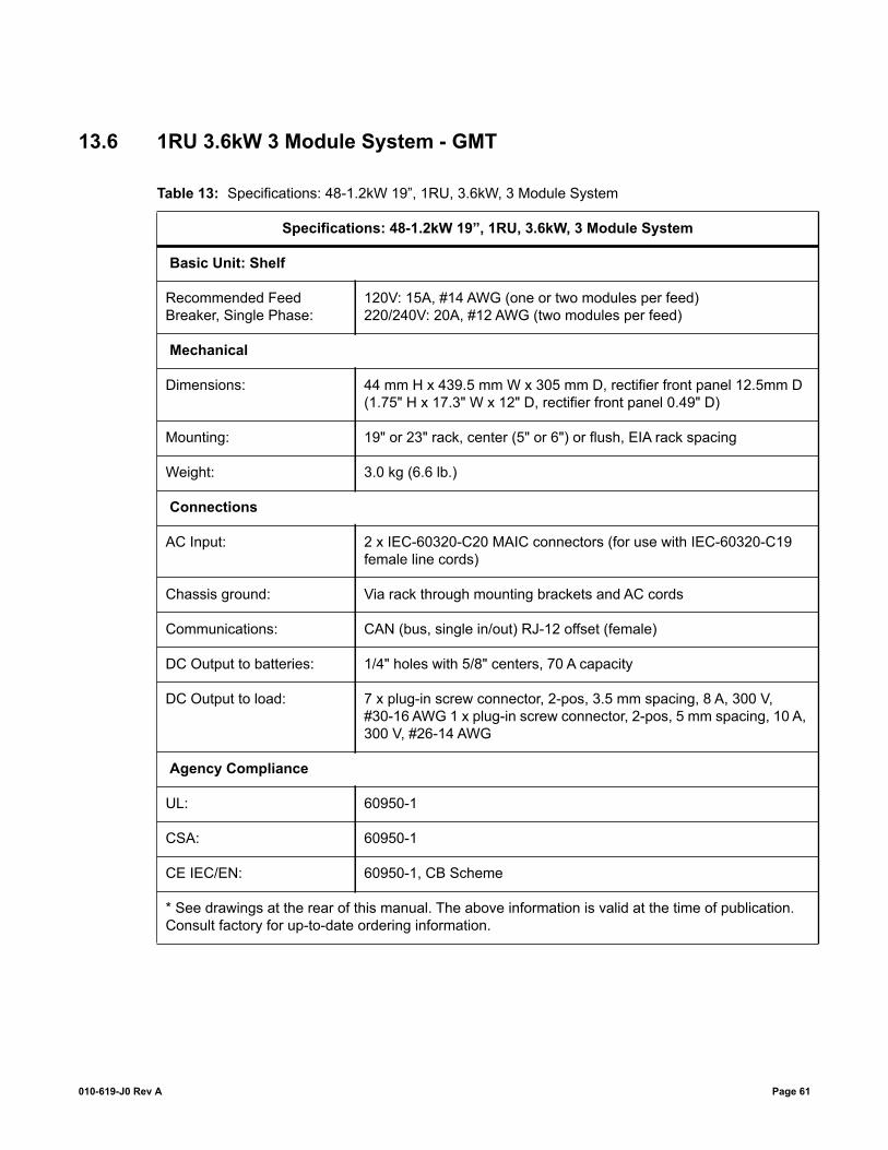
13.6 1RU 3.6kW 3 Module System - GMT
Table 13: Specifications: 48-1.2kW 19”, 1RU, 3.6kW, 3 Module System
Specifications: 48-1.2kW 19”, 1RU, 3.6kW, 3 Module System
Basic Unit: Shelf
Recommended Feed Breaker, Single Phase:
120V: 15A, #14 AWG (one or two modules per feed) 220/240V: 20A, #12 AWG (two modules per feed)
Mechanical
Dimensions: 44 mm H x 439.5 mm W x 305 mm D, rectifier front panel 12.5mm D (1.75" H x 17.3" W x 12" D, rectifier front panel 0.49" D)
Mounting: 19" or 23" rack, center (5" or 6") or flush, EIA rack spacing
Weight: 3.0 kg (6.6 lb.)
Connections
AC Input: 2 x IEC-60320-C20 MAIC connectors (for use with IEC-60320-C19 female line cords)
Chassis ground: Via rack through mounting brackets and AC cords
Communications: CAN (bus, single in/out) RJ-12 offset (female)
DC Output to batteries: 1/4" holes with 5/8" centers, 70 A capacity
DC Output to load: 7 x plug-in screw connector, 2-pos, 3.5 mm spacing, 8 A, 300 V, #30-16 AWG 1 x plug-in screw connector, 2-pos, 5 mm spacing, 10 A, 300 V, #26-14 AWG
Agency Compliance
UL: 60950-1
CSA: 60950-1
CE IEC/EN: 60950-1, CB Scheme
* See drawings at the rear of this manual. The above information is valid at the time of publication. Consult factory for up-to-date ordering information.
010-619-J0 Rev A Page 61
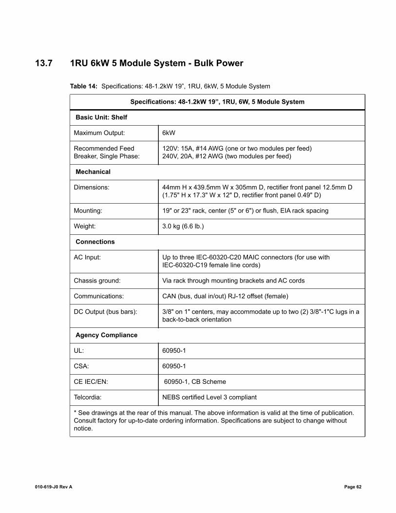
13.7 1RU 6kW 5 Module System - Bulk Power
Table 14: Specifications: 48-1.2kW 19”, 1RU, 6kW, 5 Module System
Specifications: 48-1.2kW 19”, 1RU, 6W, 5 Module System
Basic Unit: Shelf
Maximum Output: 6kW
Recommended Feed Breaker, Single Phase:
120V: 15A, #14 AWG (one or two modules per feed) 240V, 20A, #12 AWG (two modules per feed)
Mechanical
Dimensions: 44mm H x 439.5mm W x 305mm D, rectifier front panel 12.5mm D (1.75" H x 17.3" W x 12" D, rectifier front panel 0.49" D)
Mounting: 19" or 23" rack, center (5" or 6") or flush, EIA rack spacing
Weight: 3.0 kg (6.6 lb.)
Connections
AC Input: Up to three IEC-60320-C20 MAIC connectors (for use with IEC-60320-C19 female line cords)
Chassis ground: Via rack through mounting brackets and AC cords
Communications: CAN (bus, dual in/out) RJ-12 offset (female)
DC Output (bus bars): 3/8" on 1" centers, may accommodate up to two (2) 3/8"-1"C lugs in a back-to-back orientation
Agency Compliance
UL: 60950-1
CSA: 60950-1
CE IEC/EN: 60950-1, CB Scheme
Telcordia: NEBS certified Level 3 compliant
* See drawings at the rear of this manual. The above information is valid at the time of publication. Consult factory for up-to-date ordering information. Specifications are subject to change without notice.
010-619-J0 Rev A Page 62


03083405C__.sch-1 - Fri Oct 16 13:27:51 2015
CHKDRW APPDATEDESCRIPTIONLTR
REVISION
2009/022009/02
2009/022009/02MC
B
W.HW.H
TB
SCHEMATIC, SHELF,19", FR ACS, 4 MDL,CXCI, DISTRN, 1.2kW
030-834-05 C
1 2
APPROVED
CHECKED
DRAWN
DESIGN
ISSUEDATE
TITLE
DWG NO. REVSIZE
ofSHEET
S3
C ALPHA TECHNOLOGIES
THESE DESIGNS AND SPECIFICATIONS ARE CONFIDETIAL,REMAIN THE PROPERTY OF ALPHA TECHNOLOGIES AND SHALL NOT BE COPIED OR USED WITHOUT ITS WRITTEN CONSENT.
TMTECHNOLOGIES
OUTPUTS (-)FUSE HOT
CXCI I/O
LIST 80: 4LOAD CB
AC #
2
AC #
1
GN
D
L2/NL1
(+)
(-)
PCB ASSY, 19" BACKPLANE CXRC 1.2kWPART NUMBER: 707-660-10SCHEMATIC: 707-660-05
MD
LS 1
& 2
MD
LS 3
& 4
AC F
EED
AC F
EED
48V/100A
E3
E4
P2
JUMPERCAN TERMINATION
BL
+-
ALARM STRIP707-588-20
SHUNT150A/50mV
CB1
CB2
CB3
CB4
(-)
NOCNC
JUMPERLVD AUTO OVERRIDE
4 MDL 1.2kW
13
3
2
PCB ASSY, I/O INTERFACE, CXCI, 19" SHELF,
PART NUMBER: 707-672-20SCHEMATIC: 707-672-05
P4
TB11
NCCNO
NC
C
NO
NC
C
NO
K1
K2
K3
+
+
+
D1
T1
T2
V1
BATT
ERY
HO
T
22 21 20
11
10
9
19
18
17
8
7
6
5
4
15
16
K4
NO
C
NC
D2
1412
+- I1
-
-
-
JP2
BATTERY
BLA
CK
RED
RECTIFIER #1
AC
DC
CAN_COM
CAN_L
CAN_+5VCAN_H
RECTIFIER #2
(-)
(+)
RECTIFIER #3 RECTIFIER #4
CAN OUT
(+)FUSE RETURNS
TB12
TB1
TB1
E5
E6
E9
LOAD CB HOTOUTPUTS (-)
OUTPUTS (-)BATTERY HOT
BATTERYRETURNS (+)
RETURNS (+)LOAD
SCHEMATIC: 707-673-05P/N: 707-673-20PCB ASSY, 10 GMT
1
2
3
4
5
6
7
8
9
10
AC I
NPU
T
P3
LVD
SITEGROUND (+)
12
P5
P1P2P2
P1
AC
DC
CAN_COM
CAN_L
CAN_+5VCAN_H
(-)
(+)
P1
AC
DC
CAN_COM
CAN_L
CAN_+5VCAN_H
(-)
(+)
P1
AC
DC
CAN_COM
CAN_L
CAN_+5VCAN_H
(-)
(+)
P1
GN
D
L2/NL1
BATT
ERY
HO
T
D1
(CB/F
USE
TRIP
)21
K4
(AC F
AIL
)
K3
(SYS
TEM
MAJO
R)
K2
(SYT
EM M
INO
R)
K1
(LVD
1)
NC
NO
CO
M
+V1
D2
I1 (
LOAD
CU
RREN
T)
NCNO CO
M
NCNO CO
M
NCNO CO
M
21 -
T1+ - + -
T2
+ -
+5V
CAN
CAN
CO
M
CAN
LCAN
H
V2
-
V2
+
POW
ER -
POW
ER +
BATTERY HOT
D1 (CB/FUSE TRIP)2
1
K4 (AC FAIL)
K3 (SYSTEM MAJOR)
K2 (SYTEM MINOR)
K1 (LVD1)
NC
NO
COM
+V1
D2
I1 (LOAD CURRENT)
NC
NO
COM
NC
NO
COM
NC
NO
COM
2
1
-
T1+
-
+
-T2
+
-
NO
T U
SED
PCB ASSY, CX, MOTHERBOARD
J1J2J2
SCHEMATIC: 707-683-05
P4
BATT
ERY
HO
TD1
21
K4
K3
K2
K1
(LVD
1)
NCNO
CO
M
+V1
D2
I1
NCNO CO
M
NCNO
CO
M
NCNO CO
M
21 -
T1+ - + -
T2
+ -
J6
(SYT
EMM
INO
R)
(SYT
EMM
AJO
R)
(AC F
AIL
)
(CB/F
USE
TRIP
)
(LO
AD
CU
RREN
T)
CAN
CAN
_CO
M
CAN
_L
CAN
_+5V
CAN
_H
4 MDL 1.2kWPCB ASSY,CAN INTERFACE
PART NUMBER: 707-669-20SCHEMATIC: 707-669-05
J3
CAN IN
J2
P2
P5
P4
P1
P6
P/N: 747-552-04
E3
E4
E3
E4
E3
E4
E3
E4
P/N: 747-551-04
E3E2E1
A1
A2
LIST 80
F1
F2
F3
F4
F5
F6
F7
F8
F9
F10
K1
25
1
2
6
3
5
4
9
8
7
10
11
12
13
14
15
16
17
18
19
20
21
22
23
24
321
321
3456
12
26
21
21
1 2 3 4
P14-
1
P14-
2
P14-
3
P14-
4
P14-
5
P14-
6
P14-
7
P14-
8
P14-
9
P14-
10
P14-
11
P14-
12
P14-
13
P14-
14
P14-
15
P14-
16
P14-
17
P14-
18
P14-
19
P14-
20
P14-
21
P14-
22
P14-
23
P14-
24
P15-
1
P15-
2
P15-
3
P15-
4
P15-
6
P15-
5
P15-
7
P15-
8
P15-
10
P15-
9
P15-
11
P15-
12
P15-
13
P15-
14
12
34
E63
E64
E65
E66
12
34
12
34
12
34
321
321
2322212019181716151413121110789453 621 24 25 26
E82
E83
21 3 4
3456
12
2P2
1-B
1P2
1-A
3P2
1-C
4P2
1-D
2
1
1N40
05
1
2
1
2
1
2
1
2
1
2
1
2
1
2
1
3
4
2
1
2
1
2
PB 2009/06 MCCOPY OF 707-486-05 REV A TBJLMA 2011/01 JKECO 10704, LIST 80 ADDED TBWHB 2012-06 JKBATT O/P Changed, BP03130 TBWHC 2015/10 JKOption 400 Added LSWH
ALM
HOT
COMMON
AC_1 AC_1
AC1_L1
AC1_L2
AC1_L1
AC1_L2
AC_2
AC2_L1
AC2_L2
AC_2
AC2_L1
AC2_L2
CXCI_INTERFACE
K1_
C
K1_
NO
K1_
NC
K2_
C
K2_
NO
K2_
NC
K3_
C
K3_
NO
K3_
NC
K4_
C
K4_
NO
K4_
NC
D1_
1
D1_
2
D2_
1
D2_
2
V1_
+
V1_
-
T1_+
T1_-
T2_+
T2_-
I1_+
I1_-
BATT
_HO
T
K1_C
K1_NO
K1_NC
K2_C
K2_NO
K2_NC
K3_C
K3_NO
K3_NC
K4_C
K4_NO
K4_NC
D1_1
D1_2
D2_1
D2_2
V1_+
V1_-
T1_+
T1_-
T2_+
T2_-
I1_+
I1_-
BATT_HOT
CAN CAN CAN
CAN_LCAN_H
CAN_+5VCAN_COM
CAN_LCAN_H
CAN_+5VCAN_COM
CAN_LCAN_H
CAN_+5VCAN_COM
CAN_LCAN_H
CAN_+5VCAN_COM
CAN CAN
_LCAN
_HCAN
_+5V
CAN
_CO
M
CAN
_LCAN
_HCAN
_+5V
CAN
_CO
M
+/-POWER_BUSBAR
+POWER
-POWER
+POWER
-POWER
+POWER
-POWER
+POWER
-POWER
+POWER
-POWER
-POWER
+POWER
AC2_
L1
AC2_
L2
AC1_
L2
AC1_
L1
+PO
WER
-PO
WER

03083405C__.sch-2 - Fri Oct 16 13:27:51 2015
OUTPUTS (-)FUSE HOT
CXCI I/O
CXCI, DISTRN, 1.2kW19", FR ACS, 4 MDL,SCHEMATIC, SHELF,
C
CHKDRW APPDATEDESCRIPTIONLTR
REVISION
2009/02
2009/02
2009/02
2009/02MC
B
W.H
W.H
TB
030-834-052 2
APPROVED
CHECKED
DRAWN
DESIGN
ISSUEDATE
TITLE
DWG NO. REVSIZE
ofSHEET
S3
C ALPHA TECHNOLOGIES
THESE DESIGNS AND SPECIFICATIONS ARE CONFIDETIAL,REMAIN THE PROPERTY OF ALPHA TECHNOLOGIES AND SHALL NOT BE COPIED OR USED WITHOUT ITS WRITTEN CONSENT.
TMTECHNOLOGIES
AC #
2
AC #
1
GN
D
L2/NL1
(+)
(-)
PCB ASSY, 19" BACKPLANE CXRC 1.2kWPART NUMBER: 707-660-10SCHEMATIC: 707-660-05
MD
LS 1
& 2
MD
LS 3
& 4
AC F
EED
AC F
EED
48V/100A
E3
E4
P2
JUMPERCAN TERMINATION
BL
+-
ALARM STRIP707-588-20
SHUNT150A/50mV
CB1
CB2
CB3
CB4
(-)
NOCNC
JUMPERLVD AUTO OVERRIDE
4 MDL 1.2kW
13
3
2
PCB ASSY, I/O INTERFACE, CXCI, 19" SHELF,
PART NUMBER: 707-672-20SCHEMATIC: 707-672-05
P4
NCCNO
NC
C
NO
NC
C
NO
K1
K2
K3
+
+
+
D1
T1
T2
V1
BATT
ERY
HO
T
22 21 20
11
10
9
19
18
17
8
7
6
5
4
15
16
K4
NO
C
NC
D2
1412
+- I1
-
-
-
JP2
BATTERY
BLA
CK
RED
RECTIFIER #1
AC
DC
CAN_COM
CAN_L
CAN_+5VCAN_H
RECTIFIER #2
(-)
(+)
RECTIFIER #3 RECTIFIER #4
CAN OUT
(+)FUSE RETURNS
TB12
TB1
TB1
E5
E6
E9
LOAD CB HOTOUTPUTS (-)
OUTPUTS (-)BATTERY HOT
BATTERYRETURNS (+)
RETURNS (+)LOAD
SCHEMATIC: 707-673-05P/N: 707-673-20PCB ASSY, 10 GMT
1
2
3
4
5
6
7
8
9
10
AC I
NPU
T
P3
LVD
SITEGROUND (+)
12
P5
P1P2P2
P1
AC
DC
CAN_COM
CAN_L
CAN_+5VCAN_H
(-)
(+)
P1
AC
DC
CAN_COM
CAN_L
CAN_+5VCAN_H
(-)
(+)
P1
AC
DC
CAN_COM
CAN_L
CAN_+5VCAN_H
(-)
(+)
P1
GN
D
L2/NL1
BATT
ERY
HO
T
D1
(CB/F
USE
TRIP
)21
K4
(AC F
AIL
)
K3
(SYS
TEM
MAJO
R)
K2
(SYT
EM M
INO
R)
K1
(LVD
1)
NC
NO
CO
M
+V1
D2
I1 (
LOAD
CU
RREN
T)
NCNO CO
M
NCNO CO
M
NCNO CO
M
21 -
T1+ - + -
T2
+ -
+5V
CAN
CAN
CO
M
CAN
LCAN
H
V2
-
V2
+
POW
ER -
POW
ER +
BATTERY HOT
D1 (CB/FUSE TRIP)2
1
K4 (AC FAIL)
K3 (SYSTEM MAJOR)
K2 (SYTEM MINOR)
K1 (LVD1)
NC
NO
COM
+V1
D2
I1 (LOAD CURRENT)
NC
NO
COM
NC
NO
COM
NC
NO
COM
2
1
-
T1+
-
+
-T2
+
-
NO
T U
SED
PCB ASSY, CXCI, MOTHERBOARDPART NUMBER: 707-492-20
SCHEMATIC: 707-420-05
LIST 91
J1J2J2
SCHEMATIC: 707-683-05
P4
BATT
ERY
HO
TD1
21
K4
K3
K2
K1
(LVD
1)
NCNO
CO
M
+V1
D2
I1
NCNO CO
M
NCNO
CO
M
NCNO CO
M
21 -
T1+ - + -
T2
+ -
J6
(SYT
EMM
INO
R)
(SYT
EMM
AJO
R)
(AC F
AIL
)
(CB/F
USE
TRIP
)
(LO
AD
CU
RREN
T)
CAN
CAN
_CO
M
CAN
_L
CAN
_+5V
CAN
_H
4 MDL 1.2kWPCB ASSY,CAN INTERFACE
PART NUMBER: 707-669-20SCHEMATIC: 707-669-05
J3
CAN IN
J2
P2
P5
P4
P1
P6
P/N: 747-552-04
E3
E4
E3
E4
E3
E4
E3
E4
P/N: 747-551-04
E3E2E1
A1
A2
BL
LIST 85, 92
LIST 81: 2 LOAD CB, 2 BATTERY CB
25
1
2
6
3
5
4
9
8
7
10
11
12
13
14
15
16
17
18
19
20
21
22
23
24
321
321
3456
12
F7
F4
F8
F5
F3
F2
F1
F6
F9
F10
26
21
21
1 2 3 4
P1-1
P1-2
P1-3
P1-4
P1-5
P1-6
P1-7
P1-8
P1-9
P1-1
0
P1-1
1
P1-1
2
P1-1
3
P1-1
4
P1-1
5
P1-1
6
P1-1
7
P1-1
8
P1-1
9
P1-2
0
P1-2
1
P1-2
2
P1-2
3
P1-2
4
P2-1
P2-2
P2-3
P2-4
P2-6
P2-5
P2-7
P2-8
P2-1
0
P2-9
P2-1
1
P2-1
2
P2-1
3
P2-1
4
1234
E4
E3
E6
E5
1234
1234
1234
321
321
2322212019181716151413121110789453 621 24 25 26
E1 E2
21 3 4
3456
12
2P8
-B
1P8
-A
3P8
-C4
P8-D
2
1
1N40
05
1
2
1
2
1
2
1
2
1
2
1
2
1
2
1
3
4
2
K1
1
2
1
2
ALM
HOT
COMMON
AC_1 AC_1
AC1_L1
AC1_L2
AC1_L1
AC1_L2
AC_2
AC2_L1
AC2_L2
AC_2
AC2_L1
AC2_L2
CXCI_INTERFACE
K1_
C
K1_
NO
K1_
NC
K2_
C
K2_
NO
K2_
NC
K3_
C
K3_
NO
K3_
NC
K4_
C
K4_
NO
K4_
NC
D1_
1
D1_
2
D2_
1
D2_
2
V1_
+
V1_
-
T1_+
T1_-
T2_+
T2_-
I1_+
I1_-
BATT
_HO
T
K1_C
K1_NO
K1_NC
K2_C
K2_NO
K2_NC
K3_C
K3_NO
K3_NC
K4_C
K4_NO
K4_NC
D1_1
D1_2
D2_1
D2_2
V1_+
V1_-
T1_+
T1_-
T2_+
T2_-
I1_+
I1_-
BATT_HOT
CAN CAN CAN
CAN_LCAN_H
CAN_+5VCAN_COM
CAN_LCAN_H
CAN_+5VCAN_COM
CAN_LCAN_H
CAN_+5VCAN_COM
CAN_LCAN_H
CAN_+5VCAN_COM
CAN CAN
_LCAN
_HCAN
_+5V
CAN
_CO
M
CAN
_LCAN
_HCAN
_+5V
CAN
_CO
M
+/-POWER_BUSBAR
+POWER
-POWER
+POWER
-POWER
+POWER
-POWER
+POWER
-POWER
+POWER
-POWER
-POWER
+POWER
AC2_
L1
AC2_
L2
AC1_
L2
AC1_
L1
+PO
WER
-PO
WER

SCALE:
REV
SHEET
SIZE DWG NO.
TITLE:
OF
CNTS
B1 2
030-834-06
OUTL DWG, ASSY,SHELF,19",FR ACS, 4 MDL,CXRF48-1.2kW
THESE DESIGNS AND SPECIFICATIONS ARECONFIDENTIAL, REMAIN THE PROPERTY OF
ALPHA TECHNOLOGIES LTD., AND SHALL NOT BECOPIED OR USED WITHOUT ITS WRITTEN CONSENT
© ALPHA TECHNOLOGIES LTD
CHECKED
DRAWN
DATEAPPROVALS
GIA
2009/05
2009-06
SY
LIST 80 or 81DISTRIBUTION
010-619-20POWER MODULE
OPTION 99CXCI-1CONTROLLER
LIST 90MODULE BLANK
OPTION 400CXCM1 HP CONTROLLER
REVISIONS
LTR DESCRIPTION DWN DATE CHKA EO10704 WH 2011/03 JKB REBUILT MODEL AND DRAWING. NO CHANGE TO ASSEMBLY WJD 13-JUN-14 JKC OPTION 400 ADDED WH 21-OCT-21 ZL
A
B
C
D
E
12345
D
A
C
E
B
135 4 2DO NOT SCALE DRAWING

SCALE:
REV
SHEET
SIZE DWG NO.
TITLE:
OF
CNTS
B2 2
030-834-06
OUTL DWG, ASSY,SHELF,19",FR ACS, 4 MDL,CXRF48-1.2kW
439.5 17.30
442.5 17.42
0
16.8 0.66
152.4 6.00
302.9 11.93
LIST 80
583.6 22.98
0 0.00
37.3 1.47
5.6 0.22
50.0 1.97
81.8 3.2287.3 3.44
LIST 2323" RACK, MID MOUNTING
482.6 19.00
465.0 18.31
566.0 22.28
LIST 1919" RACK, MID MOUNTING
LIST 81
DO NOT SCALE DRAWING
245 3 1
B
E
C
A
D
5 4 3 2 1
E
D
C
B
A

SCALE:
REV
SHEET
SIZE DWG NO.
TITLE:
OF
CNTS
B1 3
030-834-08
CUST. CONN. 19", FR ACS 4 MDL, CXRF48-1.2kW
THESE DESIGNS AND SPECIFICATIONS ARECONFIDENTIAL, REMAIN THE PROPERTY OF
ALPHA TECHNOLOGIES LTD., AND SHALL NOT BECOPIED OR USED WITHOUT ITS WRITTEN CONSENT
© ALPHA TECHNOLOGIES LTD
CHECKED
DRAWN
DATEAPPROVALS
MP
2009/07
2009/07
WH
CHASSIS GROUND#10-32 STUD & HARDWARE
AC IN MODULE 1 & 2
AC IN MODULE 3 & 4
CHASSIS GROUND#10-32 STUD & HARDWARE
JP2
1 2 3 4
BAT HOTBAT HOT
T2+T1+
D2
T1-T2-
V1+
V1-D2
K4-NC
K4-C
K4-NO
K2-NC
K2-C
K2-NOK1-NO
K1-C
K1-NC
K3-NO
K3-C
K3-NC
CAN IN/OUT RJ12 OFFSETPIN
123456
CAN L
CAN COM
NOT CONNECTED
NOT CONNECTED
CAN H
FUNCTION
CAN +5V
OPE
N
CA
NTE
RM
INA
TIO
N TER
MIN
ATE
D(D
EFA
ULT
)
DETAIL D
DB9 (FOR ARGUS DCMODEM USE ONLY)PIN
123456789
DTR
DCD
TX
RI
COM
CTS
RX
FUNCTION
DSRRTS
ETHERNET RJ45PIN
12345678
NOT CONNECTED
TX+
RX+
NOT CONNECTED
NOT CONNECTED
TX-
FUNCTION
RX-NOT CONNECTED
1
1
8
LCD SCREEN(V/A)
CXCI RESET SWITCHSOFT RESET-PUSH ONCEI/P RESET-HOLD FOR 3 SEC.
SYSTEM STATUS LEDS
DISPLAY PUSHBUTTONTOGGLE SWITCH(V/A)
P
B
MODEM
RST
A/V
!
9
OPTION 99
43LVD21
AUTO (DEFAULT)IN
(-) (+)
109
7654321
8F8
F1F2F3F4F5F6F7
F9F10
F8
F1F2F3F4F5F6F7
F9F10
GMT DISTRIBUTION PANEL(30A MAX)
OPTION 400
DETAIL A
1
8
ETHERNET10/100
DETAIL B
USB 2.0PORT
DETAIL D
RESET
STATUS DISPLAY
DETAIL C
MENU SELECT /BUTTON C
MENUCONTROL ALARM
STATUS
REVISIONS
LTR DESCRIPTION DWN DATE CHKA Eo 10704, LIST 81 ADDED WH 2011/03 JKB "LOAD CB RETURNS" ON SHT 2 WAS "LOAD CB OUTPUTS" WJD 12-JUN-14 JKC OPTION 400 ADDED WH 22-OCT-15 LS
A
B
C
D
E
12345
D
A
C
E
B
135 4 2DO NOT SCALE DRAWING

SCALE:
REV
SHEET
SIZE DWG NO.
TITLE:
OF
CNTS
B2 3
030-834-08
CUST. CONN. 19", FR ACS 4 MDL, CXRF48-1.2kW
LIST 80
DISTRIBUTION FRONT VIEWFRONT PANEL HIDDEN AND GMT FUSE HIDDEN
LOAD CB OUTPUTS ( - )4 x 1/4" - 20 HARDWARE
ON 5/8" CENTRES
LOAD CB RETURNS ( + )4 x 1/4" - 20 HARDWARE
ON 5/8" CENTRES(REF)
LOOSEN THUMBSCREW ANDSLIDE OVER TO ACCESSLOAD CB RETURNS.
SITE GROUND ( + )1 x 1/4" - 20 HARDWAREON 5/8" CENTRES(REF)
DISTRIBUTION SIDE VIEWBATTERY RETURNS ( + )2 x 1/4" - 20 HARDWARE
ON 5/8" CENTRES
BATTERY OUTPUTS ( - )2 x 1/4" - 20 HARDWAREON 5/8" CENTRES
B
DO NOT SCALE DRAWING
245 3 1
B
E
C
A
D
5 4 3 2 1
E
D
C
B
A

SCALE:
REV
SHEET
SIZE DWG NO.
TITLE:
OF
CNTS
B3 3
030-834-08
CUST. CONN. 19", FR ACS 4 MDL, CXRF48-1.2kW
CB1 BATT 1
CB2 BATT 2
CB1 LOAD 1
CB2 LOAD 2
DISTRIBUTION FRONT VIEWFRONT PANEL HIDDEN AND GMT FUSE HIDDEN
BATTERY & LOAD RETURNS ( + )6 x 1/4" - 20 HARDWAREON 5/8" CENTRES
DISTRIBUTION SIDE VIEW
SITE GROUND ( + )1 x 1/4" - 20 HARDWAREON 5/8" CENTRES(REF)
LOOSEN THUMBSCREW ANDSLIDE OVER TO ACCESSLOAD CB RETURNS.
BATTERY OUTPUTS ( - )2 x 1/4" - 20 HARDWAREON 5/8" CENTRES
LOAD CB OUTPUTS ( - )4 x 1/4" - 20 HARDWAREON 5/8" CENTRES
DO NOT SCALE DRAWING
245 3 1
B
E
C
A
D
5 4 3 2 1
E
D
C
B
A

D.D
WHSCHEMATIC, Shelf
030-835-04 B
TITLE
SIZE DWG NO. REVB
DATE
DRAWN
CHECKED
APPROVALS
19", 1RU, 4 MdlCXRF48-1.2kW
2009-04-10
2009-04-10
REVISIONSLTR DESCRIPTION DATEDRW CHK
THESE DESIGNS AND SPECIFICATIONS ARECONFIDENTIAL, REMAIN THE PROPERTY OFALPHA TECHNOLOGIES LTD., AND SHALL NOT BECOPIED OR USED WITHOUT ITS WRITTEN CONSENT
1 1SHEET ofSCALE NTS© ALPHA TECHNOLOGIES LTD
(+)
(-)
P2JUMPER
CAN TERMINATION
RECTIFIER #1
AC
DC
CAN_COM
CAN_L
CAN_+5VCAN_H
(-)
(+)
BA
TTE
RY
HO
T
D1
(CB
/FU
SE
TR
IP)
D1-
2
D1-
1K
4 (A
C F
AIL
)
K3
(SY
STE
M M
AJO
R)
K2
(SY
TEM
MIN
OR
)
K1
NC
K1
NO
K1
CO
M
I1 (L
OA
D C
UR
RE
NT)
K2
NC
K2
NO
K2
CO
M
K3
NC
K3
NO
K3
CO
M
K4
NC
K4
NO
K4
CO
M
+5V
CA
NC
AN
CO
M
CA
NL
CA
NH
V2
-
V2
+
PO
WE
R -
PO
WE
R +
NO
T U
SE
D
PCB ASSY, CX, MOTHERBOARD
SCHEMATIC: 707-684-05
BA
TTE
RY
HO
T
D1
1
K4
K3
K2
K1
(LV
D1)
NO
NC
CO
M
+V
1
D2
I1
NC
NO
CO
M
NC
NO
CO
M
NC
NO
CO
M
-
T1 T2(SY
TEM
MIN
OR
)
(SY
TEM
MA
JOR
)
(AC
FA
IL)
(CB
/FU
SE
TR
IP)
(LO
AD
CU
RR
EN
T)
CAN
CA
N_C
OM
CA
N_L
CA
N_+
5VC
AN
_H
CAN IN
J2
SYSTEMOUTPUT
DB 25 CXC I/O INTERFACE
E4
E3
E6
E5
E1 E2
3
4
5
6
1
2
K1_
NO
AC1_L1
AC1_L2
+PO
WER
+POWER
+POWER
-PO
WER
-POWER
-POWER
K1_
C
K1_
NC
K2_
CK
2_N
O
K2_
NC
K3_
CK
3_N
O
K3_
NC
K4_
CK
4_N
O
K4_
NC
D1_
1D
1_2
D2_
1D
2_2
V1_
+V
1_-
T1_+
T1_-
T2_+
T2_-
I1_+
I1_-
BA
TT_H
OT
CAN_L
CA
N_L
CAN_H
CA
N_H
CAN_+5V
CA
N_+
5V
CAN_COM
CA
N_C
OM
CXCI_INTERFACE
CHGND
1234789101314 561112
P2
NO
T U
SE
D
NO
T U
SE
D
K1
(LV
D1)
1234789101314171819202324 56111215162122
P1
D2-
1
D2-
2D
2V
1+
V1-
V1
T1+
T1-
T1T2
+
T2-
T1I1
+
I1-
1234789101314171819202324 56111215162122
J1
1234789101314 561112
J2
1 202 213 224 235 246 257 8 9 10 11 12 1314 15 16 17 18 19
2627
J3
12 2 + - + - + -
1 2 3 4
J6
1234
AC #2
AC #1
L2/NL1
MDLS 1 & 2 MDLS 3 & 4AC FEEDAC FEED
AC INPUT
321A
C1_
L1
AC
1_L2
AC
2_L1
AC
2_L2CHGND
321
L2/NL1
321
CHGND
321
CHGND CHGND
+/-POWER_BUSBAR
CAN
RECTIFIER #2 RECTIFIER #3 RECTIFIER #4
AC
DC
CAN_COM
CAN_L
CAN_+5VCAN_H
(-)
(+)
AC1_L1
AC1_L2
+POWER
-POWER
CAN_LCAN_HCAN_+5VCAN_COM
1234
AC
DC
CAN_COM
CAN_L
CAN_+5VCAN_H
(-)
(+)
AC1_L1
AC1_L2
+POWER
-POWER
CAN_LCAN_HCAN_+5VCAN_COM
1234
AC
DC
CAN_COM
CAN_L
CAN_+5VCAN_H
(-)
(+)
AC1_L1
AC1_L2
+POWER
-POWER
CAN_LCAN_HCAN_+5VCAN_COM
1234
CHGND CHGND CHGND
WHA 2015-01-10 MPBP12708, Connection on DB25 (P4) CorrectedWHB 2015-09-10 MPREV A was PADS Schematic
PIAC10101COAC101A
PIAC10202COAC102B
PIAC10303COAC103C
PIAC?03COAC?C
PIAC?02COAC?B
PIAC?01COAC?A
PIE101
COE1
PIE201
COE2
PIE301COE3
PIE401COE4
PIE501COE5 PIE5a01COE5a
PIE601COE6 PIE6a01COE6a
PIE701
PIE702
COE7
PIE801
PIE802
COE8
PIE901
COE9PIE?01COE?
PIE?01
PIE?01
PIE?01
PIE?01
PIE?01
PIE?01
PIE?01
PIE?01
PIE?01
PIE?01
PIE?01
PIGND201
COGND2
PIJ101PIJ102PIJ103PIJ104PIJ105PIJ106PIJ107PIJ108PIJ109PIJ1010PIJ1011PIJ1012PIJ1013PIJ1014PIJ1015PIJ1016PIJ1017PIJ1018PIJ1019PIJ1020PIJ1021PIJ1022PIJ1023PIJ1024
COJ1
PIJ201PIJ202PIJ203PIJ204PIJ205PIJ206PIJ207PIJ208PIJ209PIJ2010PIJ2011PIJ2012PIJ2013PIJ2014COJ2
PIJ301 PIJ302 PIJ303 PIJ304 PIJ305 PIJ306 PIJ307 PIJ308 PIJ309 PIJ3010 PIJ3011 PIJ3012 PIJ3013PIJ3014 PIJ3015 PIJ3016 PIJ3017 PIJ3018 PIJ3019 PIJ3020 PIJ3021 PIJ3022 PIJ3023 PIJ3024 PIJ3025
PIJ3026
PIJ3027
COJ3
PIJ401
PIJ402
PIJ403
PIJ404
PIJ405
PIJ406
COJ4
PIJ601 PIJ602 PIJ603 PIJ604
COJ6
PIJP401 PIJP402
COJP4
PIP101PIP102PIP103PIP104PIP105PIP106PIP107PIP108PIP109PIP1010PIP1011PIP1012PIP1013PIP1014PIP1015PIP1016PIP1017PIP1018PIP1019PIP1020PIP1021PIP1022PIP1023PIP1024COP1
PIP201PIP202PIP203PIP204PIP205PIP206PIP207PIP208PIP209PIP2010PIP2011PIP2012PIP2013PIP2014COP2
PIP301
PIP302
PIP303
PIP304
COP3PIP401
PIP402
PIP403
PIP404
COP4PIP501
PIP502
PIP503
PIP504
COP5PIP601
PIP602
PIP603
PIP604
COP6
PIR401 PIR402
COR4
PITB?03COTB?C
PITB?03 PITB?02COTB?B
PITB?02 PITB?01COTB?A
PITB?01
NL000POWER0BUSBAR
PIE101
PIE401
PIE801
PIE802
PIE?01
NL0POWER
PIE201
PIE301
PIE701
PIE702
PIE?01
NL0POWER
PIAC10101
PIE601 PIE6a01 PIE?01NLAC10L1
PIAC10303
PIE501 PIE5a01 PIE?01NLAC10L2
PIAC?01
NLAC20L1PIAC?03
NLAC20L2
PIJ3013NLBATT0HOT
NLCAN
PIJ603
PIP303 PIP403 PIP503 PIP603NLCAN005V
PIJ604
PIP304 PIP404 PIP504 PIP604NLCAN0COM
PIJ602
PIP302 PIP402 PIP502 PIP602NLCAN0H
PIJ601
PIP301 PIP401 PIP501 PIP601NLCAN0L
PIAC10202 PIAC?02
PIE901 PIE?01PIGND201
PITB?02
NLCXCI0INTERFACE
PIJ307NLD101
PIJ3020NLD102
PIJ308NLD201
PIJ3021NLD202
PIJ3012NLI100
PIJ3025NLI100
PIJ301NLK10C
PIJ302NLK10NC
PIJ3014NLK10NO
PIJ303NLK20C
PIJ3015NLK20NC
PIJ3016NLK20NO
PIJ3017NLK30C
PIJ304NLK30NC
PIJ305NLK30NO
PIJ306NLK40C
PIJ3019NLK40NC
PIJ3018NLK40NO
PIJ101PIJ102PIJ103PIJ104PIJ105PIJ106PIJ107PIJ108PIJ109PIJ1010PIJ1011PIJ1012PIJ1013PIJ1014PIJ1015PIJ1016PIJ1017PIJ1018PIJ1019PIJ1020PIJ1021PIJ1022PIJ1023PIJ1024PIJ201PIJ202PIJ203PIJ204PIJ205PIJ206PIJ207PIJ208PIJ209PIJ2010PIJ2011PIJ2012PIJ2013PIJ2014
PIJ3026
PIJ3027
PIJ401
PIJ402
PIJ403
PIJ404
PIJ405
PIJ406
PIJP401
PIR401
PIJP402
PIR402
PIP101PIP102PIP103PIP104PIP105PIP106PIP107PIP108PIP109PIP1010PIP1011PIP1012PIP1013PIP1014PIP1015PIP1016PIP1017PIP1018PIP1019PIP1020PIP1021PIP1022PIP1023PIP1024PIP201PIP202PIP203PIP204PIP205PIP206PIP207PIP208PIP209PIP2010PIP2011PIP2012PIP2013PIP2014
PITB?01PITB?01 PITB?03PITB?03
PIJ3010NLT100
PIJ3023NLT100
PIJ3011NLT200
PIJ3024NLT200
PIJ309NLV100
PIJ3022NLV100

SCALE:
REV
SHEET
SIZE DWG NO.
TITLE:
OF
BNTS
B1 1
030-835-06
OUTL, DWG, SHELF,19",1RU HOR, 4MDL,CXRF48-1.2kW
THESE DESIGNS AND SPECIFICATIONS ARECONFIDENTIAL, REMAIN THE PROPERTY OF
ALPHA TECHNOLOGIES LTD., AND SHALL NOT BECOPIED OR USED WITHOUT ITS WRITTEN CONSENT
© ALPHA TECHNOLOGIES LTD
CHECKED
DRAWN
DATEAPPROVALS
JM
9/3/2015
9/3/2015
WH
THIRD ANGLE PROJECTION
UNLESS OTHERWISE SPECIFIEDDIM ARE IN MM
INTERPRET DIM AND TOL PERASME Y14.5M-1994
XX.XX.XXANGULAR:
1
1
0.50.25
PRODUCT TO BE FABRICATED ACCORDING TO ATL PRODUCTION STANDARD 07000011.
NOTES UNLESS OTHERWISE SPECIFIED:
010-619-20 MODULE (4x)
0180054-001 or018-598-20
0 12.0 17.0
152.4
308.1
325.0
365.2
0
319.9
358.0
0
105
.5
130
.9
308
.7
334
.1
439
.5
LIST 19:6" OFFSET
FOR 19" RACK
18.0
439.5
482.6
583.6
465.0
566.0
LIST 24: 6" OFFSET FOR 23" RACK
LIST 24: 6" OFFSET FOR 23" RACK
443.5
0
376.9
319.9
KYDEX COVER
REVISIONS
LTR DESCRIPTION DWN DATE CHK
PC REDESIGNED, PA, PB NOT RELEASED WH 2009/05A REDESIGNED ZL 2014/01B REVERSED TO OLD DESIGN WH 2015/09
A
B
C
D
E
12345
D
A
C
E
B
135 4 2DO NOT SCALE DRAWING

SCALE:
REV
SHEET
SIZE DWG NO.
TITLE:
OF
BNTS
B1 1
030-835-08
CUSTOMER CONN. SHELF 19", 1RU HOR 4MDL
THESE DESIGNS AND SPECIFICATIONS ARECONFIDENTIAL, REMAIN THE PROPERTY OF
ALPHA TECHNOLOGIES LTD., AND SHALL NOT BECOPIED OR USED WITHOUT ITS WRITTEN CONSENT
© ALPHA TECHNOLOGIES LTD
CHECKED
DRAWN
DATEAPPROVALS
MC
5/15/2009
5/15/2009
WH
+ -
CAN IN RJ12 OFFSETPIN
123456
CAN L
CAN COM
NOT CONNECTED
NOT CONNECTED
CAN H
FUNCTION
CAN +5V
OPEN
CANTERMINATION
TERMINATED(DEFAULT)
DETAIL A
OPTION 99
DETAIL B
1 8
ETHERNET10/100
DB9 (FOR ARGUS DCMODEM USE ONLY)PIN
123456789
DTR
DCD
TX
RI
COM
CTS
RX
FUNCTION
DSRRTS
DETAIL C
5
9 6
1
K3-NC
12
1011
I1+T2+T1+
D1-1K4-COM
FUNCTION
K1-NC
D2-1
K3-NO
V1+
K2-COM
K1-COM
987654321
PIN
CXCI DB-25(ALARM)
23
D1-2
K3-COM
I1-
15
D2-2
K2-NC
2513
22
18 K4-NO
14
T1-
K2-NO
21
K4-NC
17
V1-
20
24
16
K1-NO
19
T2-
BATT HOT
DETAIL D
14
1
25
13
DETAIL G
STATUS DISPLAY
RESETDETAIL F
MENUCONTROL
MENUSELECT /BUTTON C
ALARMSTATUSDETAIL E
USB 2.0 PORT
BACKUPBATTERY
BATTERYHOLDER
OPTION 400
REVISIONS
LTR DESCRIPTION DWN DATE CHK
P/A First Release WH 05/01/2009 MCA New Design ZL 01/09/2014 KLB Reversed to old Design, Option 400 Added WH 09/09/2015 LS
A
B
C
D
E
12345
D
A
C
E
B
135 4 2DO NOT SCALE DRAWING
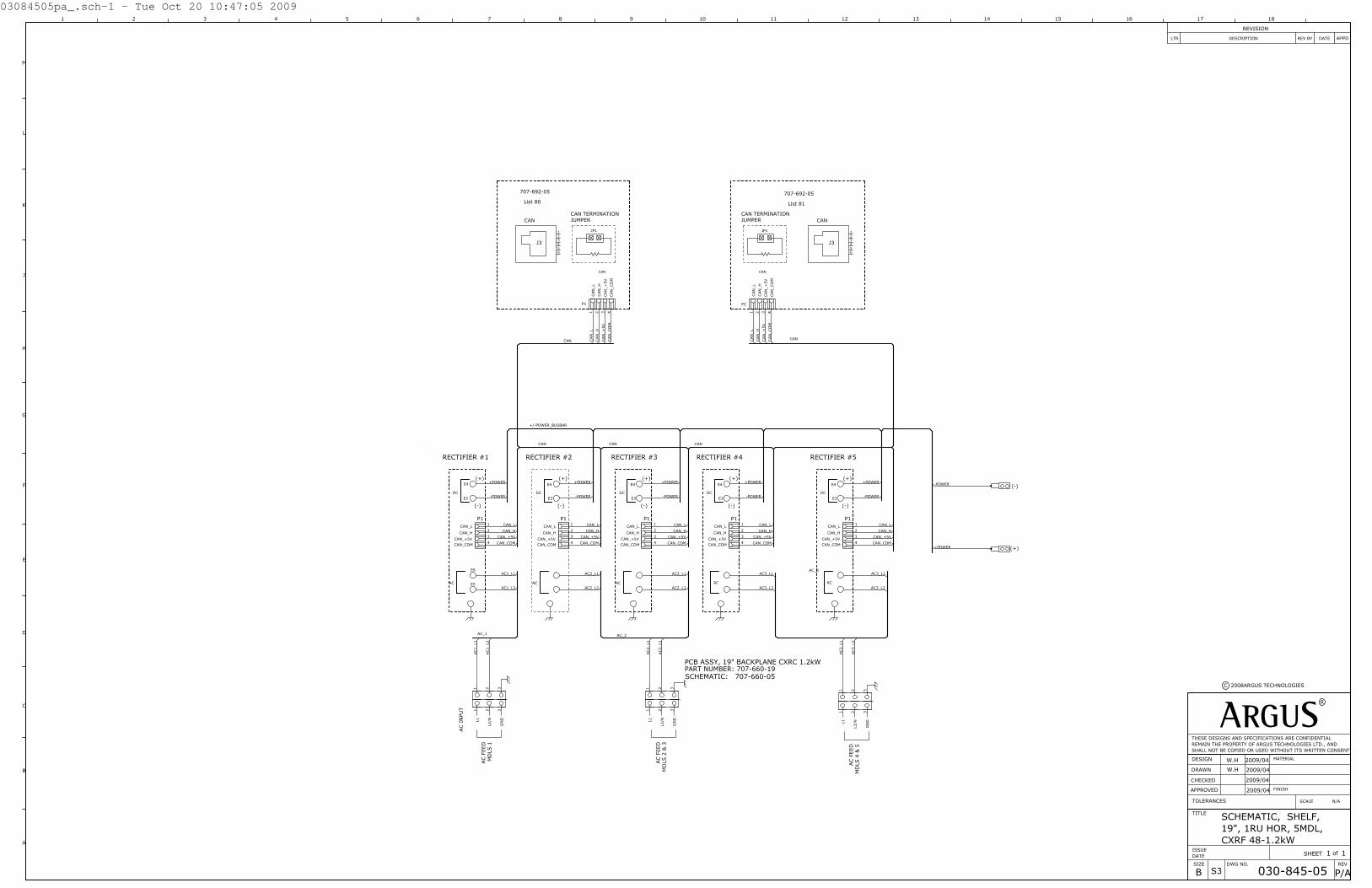
03084505pa_.sch-1 - Tue Oct 20 10:47:05 2009
CXRF 48-1.2kW19", 1RU HOR, 5MDL,
ARGUS2009/04
2009/04
2009/04
2009/04
B
W.H
W.H
SCHEMATIC, SHELF,
030-845-05 P/A
1 1
MATERIAL
FINISH
SCALE N/A
THESE DESIGNS AND SPECIFICATIONS ARE CONFIDENTIALREMAIN THE PROPERTY OF ARGUS TECHNOLOGIES LTD., ANDSHALL NOT BE COPIED OR USED WITHOUT ITS WRITTEN CONSENT
R
APPROVED
CHECKED
DRAWN
DESIGN
TOLERANCES
ISSUEDATE
TITLE
DWG NO. REVSIZE
ofSHEET
C 2008ARGUS TECHNOLOGIES
S3
REV BY
REVISION
LTR DESCRIPTION DATE APPD
1615 181713 149 10 11 125 6 7 831
F
G
H
J
L
42
M
K
E
D
C
B
A
GN
D
L2/NL1
(+)
(-)
PCB ASSY, 19" BACKPLANE CXRC 1.2kWPART NUMBER: 707-660-19SCHEMATIC: 707-660-05
MD
LS 1
MD
LS 2
& 3
AC F
EED
AC F
EED
JP1
JUMPERCAN TERMINATION
RECTIFIER #1
AC
DC
CAN_COM
CAN_L
CAN_+5V
CAN_H
RECTIFIER #2
(-)
(+)
RECTIFIER #3 RECTIFIER #4AC I
NPU
T
P1
AC
DC
CAN_COM
CAN_L
CAN_+5V
CAN_H
(-)
(+)
P1
AC
DC
CAN_COM
CAN_L
CAN_+5V
CAN_H
(-)
(+)
P1
AC
DC
CAN_COM
CAN_L
CAN_+5V
CAN_H
(-)
(+)
P1
GN
D
L2/NL1
P1
CAN
CAN
_CO
M
CAN
_L
CAN
_+
5V
CAN
_H
CAN
J3
E3
E4
E3
E4
E3
E4
RECTIFIER #5
AC
DC
CAN_COM
CAN_L
CAN_+5V
CAN_H
(-)
(+)
P1
E3
E4
MD
LS 4
& 5
AC F
EED
GN
D
L2/NL1
JP1
JUMPERCAN TERMINATION
P2
CAN
CAN
_CO
M
CAN
_L
CAN
_+
5V
CAN
_H
CAN
J3
707-692-05
List 80
707-692-05
List 81
321
321
1
2
3
4
E4
E3
E6
E5
1
2
3
4
1
2
3
4
1
2
3
4
321
321
21 3 4
3456
12
1
2
3
4
321
321
21 3 4
3456
12
AC_1
AC1_L1
AC1_L2
AC_2
AC2_L1
AC2_L2
CAN CAN CAN
CAN_L
CAN_H
CAN_+5V
CAN_COM
CAN_L
CAN_H
CAN_+5V
CAN_COM
CAN_L
CAN_H
CAN_+5V
CAN_COM
CAN_L
CAN_H
CAN_+5V
CAN_COM
CAN CAN
_L
CAN
_H
CAN
_+
5V
CAN
_CO
M
+/-POWER_BUSBAR
+POWER
-POWER
+POWER
-POWER
+POWER
-POWER
+POWER
-POWER
AC1_L2
AC1_L1
-POWER
+POWER
+POWER
-POWER
CAN_L
CAN_H
CAN_+5V
CAN_COM
AC_3
AC3_L1
AC3_L2
AC3_L1
AC3_L2
AC2_L2
AC2_L1
CANCAN
_CO
M
CAN
_+
5V
CAN
_H
CAN
_L
AC2_L1
AC2_L2
AC3_L1
AC3_L2

©
NAME DATE
APPROVED
CHECKED
DRAWN
DESIGN 2009/05
2009/05
2009/10
2009/10
SY
WH
SY
MC
SCALE:
THESE DESIGNS AND SPECIFICATIONS ARE CONFIDENTIAL, REMAINTHE PROPERTY OF ARGUS TECHNOLOGIES LTD., AND SHALL NOT
BE COPIED OR USED WITHOUT ITS WRITTEN CONSENT.
TYPE
0.5
D2
10.50.05 0.002]
[ 0.040] [ 0.020] [
UNITS: mm [in] X [X.X] X.X [X.XX] X.XX [X.XXX] ANGULAR:
OF
7/28/2008 ARGUS TECHNOLOGIES
TITLE:
ISSUEDATESIZEB
DWG NO.
OUTLINE DRAWING, ASSY,SHELF,19",1RU HOR,
5MDL,CXRF48-1.2kW
030-845-06
SHEET
NTS
REV
P/A
1 1
ITEM
QTY
REVISIONSDESCRIPTIONLTR APPDDATEDWN CHKD
0
13.43341.0
302.9 11.93
325.0 12.80
0 105.
54.
15
130.
95.
15
308.
712
.15
334.
113
.15
439.
517
.30
12.0 0.47
13.9 0.55
152.4 6.00
06.1 0.24
37.9 1.4944.0 1.73
465.0 18.31
566.0 22.28
0
372.4 14.66
018.0
0.71
LIST 19:6" OFFSET FOR 19" RACK
010-619-20 MODULE (5x)
482.6 19.00
439.5 17.30
LIST 24: 6" OFFSET FOR 23" RACK
583.6 22.98
443.5 17.46
©

©
NAME DATE
APPROVED
CHECKED
DRAWN
DESIGN 2009/05
2009/05
2009/05
2009/05
WH
WH
SY
MC
SCALE:
THESE DESIGNS AND SPECIFICATIONS ARE CONFIDENTIAL, REMAINTHE PROPERTY OF ARGUS TECHNOLOGIES LTD., AND SHALL NOT
BE COPIED OR USED WITHOUT ITS WRITTEN CONSENT.
TYPE
0.5
D2
10.50.05 0.002]
[ 0.040] [ 0.020] [
UNITS: mm [in] X [X.X] X.X [X.XX] X.XX [X.XXX] ANGULAR:
OF
5/26/2009 ARGUS TECHNOLOGIES
TITLE:
ISSUEDATESIZEB
DWG NO.
CUSTOMER CONN. SHELF 19", 1RU HOR 5MDL
030-845-08
SHEET
NTS
REV
P/A
1 1
ITEM
QTY
(DE
FA
UL
T)
CA
NT
ER
MIN
AT
ION
OP
EN
TE
RM
INA
TE
D
6
CAN L
CAN COM
NOT CONNECTED
NOT CONNECTED
CAN H
FUNCTION
CAN IN RJ12 OFFSET
PIN12345
CAN +5V
PIN123456
CAN L
CAN COM
NOT CONNECTED
NOT CONNECTED
CAN H
FUNCTION
CAN IN RJ12 OFFSET
CAN +5V
REVISIONSDESCRIPTIONLTR APPDDATEDWN CHKD
TE
RM
INA
TIO
N
OP
EN
(DE
FA
UL
T)
CA
N
TE
RM
INA
TE
D
+
DETAIL B
BDETAIL AA
-
©

D
CHKDRW DATEDESCRIPTIONLTR
REVISION
2010/02
2010/02
2010/02
2010/02GIA
B
WH
WH
MC
SCHEMATIC, SHELF, 19"1RU, HOR, 3 MDL,CXRF 1.2kW
030-851-051 1
APPROVED
CHECKED
DRAWN
DESIGN
ISSUEDATE
TITLE
DWG NO. REVSIZE
ofSHEET
S3
C ALPHA TECHNOLOGIES
THESE DESIGNS AND SPECIFICATIONS ARE CONFIDETIAL,REMAIN THE PROPERTY OF ALPHA TECHNOLOGIES AND SHALL NOT BE COPIED OR USED WITHOUT ITS WRITTEN CONSENT.
TMTECHNOLOGIES
AC
#2
AC
#1
GN
D
L2/NL1
PCB ASSY, 19" BACKPLANE CXRC 1.2kWPART NUMBER: 707-660-19SCHEMATIC: 707-660-05
MD
LS 1
& 2
MD
L 3
AC F
EED
AC F
EED
RECTIFIER #1
DC
CAN_COM
CAN_L
CAN_+5V
CAN_H
RECTIFIER #2
(-)
(+)
RECTIFIER #3
AC I
NPU
T
P1P2P2
P1
DC
CAN_COM
CAN_L
CAN_+5VCAN_H
(-)
(+)
P1
AC INPUT
DC
CAN_COM
CAN_L
CAN_+5VCAN_H
(-)
(+)
P1
GN
D
L2/NL1
BATT
ERY
HO
T
D1
(CB/F
USE
TRIP
)21
K4
(AC
FAIL
)
K3
(SYS
TEM
MAJO
R)
K2
(SYT
EM M
INO
R)
K1
(LVD
1)
NC
NO
CO
M
+V1
D2
I1 (
LOAD
CU
RREN
T)
NCNO CO
M
NCNO CO
M
NCNO CO
M
21 -
T1+ - + -
T2
+ -
+5V
CAN
CAN
CO
M
CAN
LC
AN
H
V2
-
V2
+
POW
ER -
POW
ER +
NO
T U
SED
PCB ASSY, CX, MOTHERBOARD
J1
J2J2
SCHEMATIC: 707-818-05
J3
BATT
ERY
HO
TD1
21
K4
K3
K2
K1
(LVD
1)N
CN
O
CO
M
+V1
D2
I1
NCNO CO
M
NCNO
CO
M
NCNO CO
M
21 -
T1+ - + -
T2
+ -
J6
(SYT
EMM
INO
R)
(SYT
EMM
AJO
R)
(AC
FAIL
)
(CB/F
USE
TRIP
)
(LO
AD
CU
RREN
T)
CAN
CAN
_CO
M
CAN
_L
CAN
_+5V
CAN
_H
CAN IN
J2
E3
E4
E3
E4
(+)
(-)
48V/75A
E9
E10+-
SHUNT100A/50mV
D1
+
-I1
(+)FUSE RETURNSTB12
E5
E6
E9
SCHEMATIC: 707-815-05P/N: 707-815-20PCB ASSY, 8 GMT
1
2
3
4
56
7
8
9
10
E3
A1
A2
1112
1314
1516
E4
E5
E6
E7
E8
JP1
JP4JP5
JP6
JP7
JP8
JP3
LOAD LVDLIST 86
LOAD LVDLIST 86
BATTERY LVDLIST 87
BATTERY LVDLIST 87
JP9
NCK1 (LVD1)
E10
SCHEMATIC: 707-817-05
BATTERY HOT
BATTERY RETURN
E7
E8
P/N: 707-817-20
P/N: 707-818-20
P/N: 707-816-20
+-
BLA
CK
REDSH
UN
T
P1
J1
+-
P4J4
D1
+
P3
J3
P2
J2
BATTERY HOT
AC INPUTAC INPUTE5
E6
E5
E6
E4
E6
E3
E3A
E9, 11 E12, 13
OPTION 99 or 400
321
321
P1-1
P1-2
P1-3
P1-4
P1-5
P1-6
P1-7
P1-8
P1-9
P1-1
0
P1-1
1
P1-1
2
P1-1
3
P1-1
4
P1-1
5
P1-1
6
P1-1
7
P1-1
8
P1-1
9
P1-2
0
P1-2
1
P1-2
2
P1-2
3
P1-2
4
P2-1
P2-2
P2-3
P2-4
P2-6
P2-5
P2-7
P2-8
P2-1
0P2
-9
P2-1
1P2
-12
P2-1
3P2
-14
1234
E4
E3
E6
E5
1234
1234
321
321
12241123102292182071961841751532 16141 25 13 26
E1 E2
21 3 4
3456
12
F7
F4
F8
F5
F3
F2
F1
F6
1N40
05
1N4005
1
3
4
2
K1
1N40
05
12
12
12
12
12
12
12
12
12
12
1 2
1 2 12
3
3
12
12
1
3
4
2
K2
1N40
05
1
2
3
E15 E16
12
12
1
22
1
1 2
1 2
1 2
1 2
B 2010/04REDESIGNED GIAWHC 2015/09OPTION 400 Added LSWHD 2016/06CORRECTED LABEL ON AC FEED JKJLM
AC_1 AC_1
AC_2
CXCI_INTERFACE
K1_
C
K1_
NO
K1_
NC
K2_
C
K2_
NO
K2_
NC
K3_
C
K3_
NO
K3_
NC
K4_
C
K4_
NO
K4_
NC
D1_
1
D1_
2
D2_
1
D2_
2
V1_
+
V1_
-
T1_+
T1_-
T2_+
T2_-
I1_+
I1_-
BATT
_HO
T
CAN CAN
CAN_LCAN_H
CAN_+5VCAN_COM
CAN_LCAN_H
CAN_+5VCAN_COM
CAN_LCAN_H
CAN_+5VCAN_COM
+/-POWER_BUSBAR
+POWER
-POWER
+POWER
-POWER
+POWER
-POWER
AC
2_L1
AC
2_L2
AC
1_L2
AC
1_L1
CAN
_LC
AN
_HC
AN
_+5V
CAN
_CO
M
+PO
WER
-PO
WER
+POWER
-POWER
-POWER
+POWER
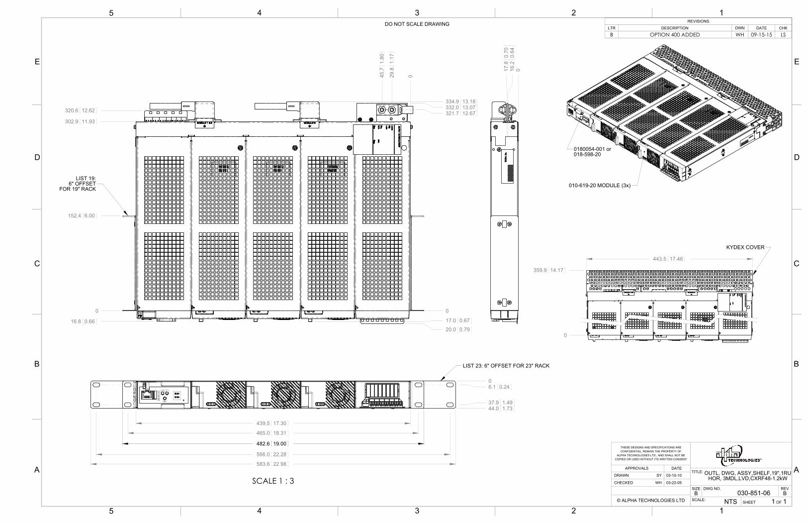
SCALE:
REV
SHEET
SIZE DWG NO.
TITLE:
OF
BNTS
B1 1
030-851-06
OUTL, DWG, ASSY,SHELF,19",1RU HOR, 3MDL,LVD,CXRF48-1.2kW
THESE DESIGNS AND SPECIFICATIONS ARECONFIDENTIAL, REMAIN THE PROPERTY OF
ALPHA TECHNOLOGIES LTD., AND SHALL NOT BECOPIED OR USED WITHOUT ITS WRITTEN CONSENT
© ALPHA TECHNOLOGIES LTD
CHECKED
DRAWN
DATEAPPROVALS
WH
03-10-10
03-22-05
SY
439.5 17.30
583.6 22.98
465.0 18.31
566.0 22.28
482.6 19.00
0
37.9 1.49
6.1 0.24
44.0 1.73
LIST 23: 6" OFFSET FOR 23" RACK
SCALE 1 : 3
LIST 19:6" OFFSET
FOR 19" RACK
0
321.7 12.67332.0 13.07
029.8
1.17
45.7
1.80
0
152.4 6.00
20.0 0.79
302.9 11.93
334.9 13.18
320.6 12.62
16.8 0.66 17.0 0.67
010-619-20 MODULE (3x)
0180054-001 or018-598-20
443.5 17.46
0
359.9 14.17
KYDEX COVER
017.8
0.70
16.2
0.64
REVISIONS
LTR DESCRIPTION DWN DATE CHK
B OPTION 400 ADDED WH 09-15-15 LS
A
B
C
D
E
12345
D
A
C
E
B
135 4 2DO NOT SCALE DRAWING

SCALE:
REV
SHEET
SIZE DWG NO.
TITLE:
OF
BNTS
B1 1
030-851-08
CUST,CONN, SHELF 19", 1RU HOR, MDL,LVD,CXRF48-1.2kW
THESE DESIGNS AND SPECIFICATIONS ARECONFIDENTIAL, REMAIN THE PROPERTY OF
ALPHA TECHNOLOGIES LTD., AND SHALL NOT BECOPIED OR USED WITHOUT ITS WRITTEN CONSENT
© ALPHA TECHNOLOGIES LTD
CHECKED
DRAWN
DATEAPPROVALS
WH
3/15/2003
3/15/2003
SY
BATT(+)
H
BATTERY RETURN (+)
BATTERY HOT (-)
AC INPUTS (2 PLACES)(SEE MANUAL FOR INSTALLATIONINSTRUCTIONS)
CAN IN RJ12 OFFSETPIN
123456
CAN L
CAN COM
NOT CONNECTED
NOT CONNECTED
CAN H
FUNCTION
CAN +5V
CANTERMINATION
OPEN
TERMINATED(DEFAULT)
ETHERNET RJ45PIN
12345678
NOT CONNECTED
TX+
RX+
NOT CONNECTED
NOT CONNECTED
TX-
FUNCTION
RX-NOT CONNECTED
DETAIL B
1 8
CAUTION!USE ONLY ALPHA DC MODEM(SEE MANUAL FOR INSTRUCTIONS)PIN
123456789
DTR
DCD
TX
RI
COM
CTS
RX
FUNCTION
DSRRTS
DETAIL C
7NC+
10+
515-
K2T2
12 1
V1
911-
T1
3+
617 13 2NC NO C
48NO
K4D2- 1 NC
16C
K3C
142 NO
CXCM1 INTERFACE(SEE MANUAL FOR INSTRUCTIONS)
7NC+
10+
515-
K2T2
12 1
V1
911-
T1
3+
617 13 2NC NO C
48NO
K4D2- 1 NC
16C
K3C
142 NO
F8F7F6F5F4 CCCCCF3 CCC F2F1
GMT FUSE DISTRIBUTION PANELMAX. 40 ADC(SEE MANUAL FOR INSTRUCTIONS)
BATTERYHOLDER
BACKUP BATTERYDETAIL G
STATUSDISPLAY
RESET
DETAIL F
MENUCONTROL
MENUSELECT/BUTTON C
STATUSDISPLAY
DETAIL E
USB 2.0 PORT
9
5
6
1
OPTION 400
REVISIONS
LTR DESCRIPTION DWN DATE CHK
B OPTION 400 ADDAD
A
B
C
D
E
12345
D
A
C
E
B
135 4 2DO NOT SCALE DRAWING


Visit us at www.alpha.ca
Due to continuing product development, Alpha Technologies reserves the right to change specifications without notice. Copyright © 2016 Alpha Technologies. All Rights Reserved. Alpha® is a registered trademark of Alpha Technologies.
Alpha Technologies Ltd.7700 Riverfront GateBurnaby, BC V5J 5M4 CanadaTel: +1 604 436 5900Fax: +1 604 436 1233Toll Free: +1 800 667 8743www.alpha.ca
Alpha Technologies Inc.3767 Alpha WayBellingham, WA 98226 United StatesTel: +1 360 647 2360Fax: +1 360 671 4936www.alpha.com
Alpha Industrial Power Inc.1075 Satellite Blvd NW.Suite 400Suwanee, GA 30024Tel: +1 678 475 3995 Fax: +1 678 584 9259www.alpha.com
Alpha Energy17825 59th Ave. NE, Suite BArlington, WA 98223United StatesTel: +1 360 435 6030Fax: +1 360 435 6019www.alpha.com
Alpha Technologies GmbH.Hansastrasse 8D-91126Schwabach, GermanyTel: +49 9122 79889 0Fax: +49 9122 79889 21www.alphatechnologies.com
Alpha Technologies Europe Ltd.Twyford House, ThorleyBishop’s StortfordHertfordshire, CM22 7PAUnited KingdomTel: +44 1279 501110Fax: +44 1279 659870www.alphatechnologies.com
Alphatec Ltd.339 St. Andrews St. Suite 101 Andrea ChambersP.O. Box 564683307 Limassol, CyprusTel: +357 25 375 675Fax: +357 25 359 595www.alpha.com
Alpha Technologies Pty Ltd.Suite 2 32-34 Peter Brock DriveEastern Creek NSW 2766AustraliaTel: +61 2 8599 6960www.alpha.com
Alpha Innovations BrasilAddress: Rua Alvares Cabral, Nº 338 – Diadema - SP09981-030BrazilTel: +55 11 2476 0150www.alphainnovations.com.br
Alpha Technologies S.A.1, Avenue Alexander FlemingB-1348 Ottignies, Louvain-la-NeuveBelgiumTel: +32 10 438 510Fax: +32 10 438 213www.alphatechnologies.eu
OutBack Power17825 59th Ave. NE, Suite BArlington, WA 98223United StatesTel: +1 360 435 6030Fax: +1 360 435 6019www.outbackpower.com
Alpha Tec Trading (Shenzhen) Co. Ltd.Suite 1903, Tower 1,China Hong Kong City,33 Canton Road,Kowloon, Hong KongTel: +852 2736 8663Fax: +852 2199 7988www.alpha.com
NavSemi Technologies Pvt. Ltd.Bengaluru, India OfficePlot No: 29 (P1) & 31 (P1),Electronic City Phase 2,Bengaluru - 560 100, India.Tel: +91 80 6539 2666www.navsemi.com
Alpha Mexico Network Power S.A. de C.V.Calle Dakota #204, of 303, Col. Nápoles.México D.F. C.P.03810, MéxicoTel: +55 5543 1114Toll Free: +01 800 0082 886www.alphapower.mx
Alpha Technologies Turkey Enerji Ltd StiAltaycesme MAh.Sarigul Sok No 33 Umut Kent Sistesi A Blok D:5 Maltepe, IstanbulTurkeyTel: +90 216 370 23 28Fax: +90 216 370 23 68www.alpha.com.tr
For technical support, contact Alpha Technologies:Canada and USA: 1-888-462-7487
International: +1-604-436-5547