Comparison of PWM control of pneumatic actuator based on energy efficiency
9
FACTA UNIVERSITATIS Ser: Elec. Energ. Vol. 25, N o 2, August 2012, pp. 93 - 101 DOI: 10.2298/FUEE1202093C COMPARISON OF PWM CONTROL OF PNEUMATIC ACTUATOR BASED ON ENERGY EFFICIENCY Stanimir Čajetinac 1 , Dragan Šešlija 2 , Vlastimir Nikolić 3 , Milica Todorović 4 1 Engineering College, Trstenik, Serbia, 2 University of Novi Sad, Faculty of Technical Sciences, Novi Sad, Serbia, 3 University of Niš, Faculty of Mechanical Engineering, Niš, Serbia, 4 Engineering College, Trstenik, Serbia, Abstract. In this paper different realizations of PWM control of pneumatic actuators are compared. The actuators are controlled by PLC and two 3/2 valves. Quality of tracking and air consumptions for different realizations of control are compared. Key words: Pneumatic actuator, PWM control, compressed air consumption 1. INTRODUCTION Intensive use of pulse wide modulation (PWM) for the control of pneumatic actuator using on/off valve caused the examining of different ways of control realization and ap- plication of various types of regulators [1-2]. There may be two basic configurations, one of which requires two 3/2 electromagnetic valves (Fig. 1) and second one, for which is required four 2/2 electromagnetic valves [3]. These configurations differ in complexity and cost, but also, areas of application are not identical, which will be analyzed in this paper. For each of these control configurations can be applied different types of regulators. In most cases, the previous research has focused on quality control in terms of speed and accuracy, and less on compressed air consumption and cost of the system [4]. How- ever, the compressed air is an expensive form of energy, it is on the choice of control methods to choose an approach that allows its saving [5]. This approach is needed for economic as well as for the environmental reasons and in recent years, much attention is paid to that. A number of methods were identified for increasing the energy efficiency of pneumatic systems [6-7]. This approach is particularly needed in applications where the amount of compressed air and its production is limited as in mobile robotic systems [4]. As a typical system of PWM control can be considered a configuration with two 3/2 valves in which each valve is connected to one cylinder chamber and works in regime of “charging” or “discharging” of that chamber. The mean value of pressure in the chamber Received March 14, 2012 Corresponding author: Stanimir Čajetinac Engineering College, Trstenik, Serbia E-mail: [email protected]
-
Upload
independent -
Category
Documents
-
view
2 -
download
0
Transcript of Comparison of PWM control of pneumatic actuator based on energy efficiency

FACTA UNIVERSITATIS Ser: Elec. Energ. Vol. 25, No 2, August 2012, pp. 93 - 101 DOI: 10.2298/FUEE1202093C
COMPARISON OF PWM CONTROL OF PNEUMATIC ACTUATOR BASED ON ENERGY EFFICIENCY
Stanimir Čajetinac1, Dragan Šešlija2, Vlastimir Nikolić3, Milica Todorović4
1Engineering College, Trstenik, Serbia, 2University of Novi Sad, Faculty of Technical Sciences, Novi Sad, Serbia,
3University of Niš, Faculty of Mechanical Engineering, Niš, Serbia, 4Engineering College, Trstenik, Serbia,
Abstract. In this paper different realizations of PWM control of pneumatic actuators are compared. The actuators are controlled by PLC and two 3/2 valves. Quality of tracking and air consumptions for different realizations of control are compared.
Key words: Pneumatic actuator, PWM control, compressed air consumption
1. INTRODUCTION
Intensive use of pulse wide modulation (PWM) for the control of pneumatic actuator using on/off valve caused the examining of different ways of control realization and ap-plication of various types of regulators [1-2]. There may be two basic configurations, one of which requires two 3/2 electromagnetic valves (Fig. 1) and second one, for which is required four 2/2 electromagnetic valves [3]. These configurations differ in complexity and cost, but also, areas of application are not identical, which will be analyzed in this paper. For each of these control configurations can be applied different types of regulators.
In most cases, the previous research has focused on quality control in terms of speed and accuracy, and less on compressed air consumption and cost of the system [4]. How-ever, the compressed air is an expensive form of energy, it is on the choice of control methods to choose an approach that allows its saving [5]. This approach is needed for economic as well as for the environmental reasons and in recent years, much attention is paid to that. A number of methods were identified for increasing the energy efficiency of pneumatic systems [6-7]. This approach is particularly needed in applications where the amount of compressed air and its production is limited as in mobile robotic systems [4].
As a typical system of PWM control can be considered a configuration with two 3/2 valves in which each valve is connected to one cylinder chamber and works in regime of “charging” or “discharging” of that chamber. The mean value of pressure in the chamber
Received March 14, 2012 Corresponding author: Stanimir Čajetinac Engineering College, Trstenik, Serbia E-mail: [email protected]
94 S. ČAJETINAC, D. ŠEŠLIJA, V. NIKOLIĆ, M. TODOROVIĆ
which is achieved in that way is proportional to the duty cycle which is a function of dif-ference between the given and measured value. This way of control will be marked as “classical PWM control” in this paper.
After achieving the desired position of actuator, impulse duty cycle by which the air flow for both chambers is regulated is 50% in classical PWM control. In that way the pre-viously reached position is sustained. This paper proposes a modification of classical PWM control so that upon reaching the stationary state sets the duty cycle to 100% which means that both chambers are connected to the source of pressure. The purpose of the proposed modification is the absence of air consumption after reaching the steady state. In paper [8] there is tested control configuration with 3/2 valves, with the realization which keeps one valve fully open to the source of pressure, and the other was working in PWM mode. The usual term for this sort of control is meter out. This paper provides character-istics comparison of the three described realizations of the PWM control: classic, meter-out with PWM control, and modified classical method that is proposed here. In all three cases two 3/2 valves were used, and the quality of tracking and air consumption are com-pared. At the same time, as the control algorithm PID controller is used.
2. THE EXPERIMENTAL SETTING
For the realization of PWM control it is necessary to measure error in real time to cal-culate duty cycle on the basis of the applied controller and to establish control signal. In the so far described realizations of these tasks they are usually performed by PCs with modules for data acquisition, or dedicated devices based on microprocessors. Thanks to a reliable, affordable price, good computer and operating skills as well as easy mainte-nance, programmable logic controllers (PLC) today play an important role in the control and process automation. In paper [9], a programmable logic controller has been used for the above described implementation of the PWM control of pneumatic actuator. For this purpose, there is formed an experimental positioning system whose pneumatic scheme and physical layout is given in Figure 1. The system consists of pneumatic cylinder, elec-tro-magnetic valves, linear potentiometer and PLC with data acquisition module.
In a steady state, a normally closed variant of the valve that is used here enables both cylinder chambers to be connected to atmospheric pressure. But if a constant signal is brought to electromagnets, the chambers are connected to the operating pressure. In the case of positional errors, the electromagnets are supplied with the series of pulses in ac-cordance with the mode of PWM control. For the operating frequency of PWM signal 25Hz is defined. A two-way cylinder was used with rod, 37 240, with guides and weights to simulate the load. A pneumatic cylinder of unknown characteristics is deliber-ately used in order to test control capabilities with an arbitrarily selected actuator.
To convert electrical signals into the air flow (electro pneumatic-interface) a solenoid valve Festo MHE2 is used. This valve is characterized by small size, compact and light-weight design and a very short opening time.

Comparison of PWM Control of Pneumatic Actuator Based on Energy Efficiency 95
Fig. 1. Pneumatic schema and experimental setting: 1-solenoid valves Festo MHE2, 2 - pneumatic cylinder, 3 - guides and weights, 4 - linear potentiometer, 5 - Omron PLC CP1L, 6- acquisition module CP1W-MAD11, 7 - 24 V power supply
The switch time is 2 ms for the version with built-in switching electronics or 7 ms without electronics [10]. The version with integrated electronics, which is used here, allows a shorter reaction time and requires less power of electrical signal to activate the valve. Here, PLC Omron CP1L with two built-in PWM outputs is used. Programmable PWM outputs allow the setting frequencies from zero to 6 kHz with a resolution of 0.1 Hz, or from zero to 32 kHz with a resolution of 1 Hz. The pulse duty cycle is also programmable and can be set to a value from zero to 100%, with a resolution of 0.1% in the first case, or 1% in the second. To measure the position, pressure and other quantities in the monitoring process, input/output module Omron CP1W-MAD11 was used, with two analog inputs and one analog output and a resolution of 1/6000 of the input range. As the test example is selected, the case where in one cycle the actuator should move into a position which is 80% of the full moving distance and after 5 s to return to the position defined with 40% of the full moving distance.
3. CLASSICAL SYSTEM OF PWM CONTROL
The classical PWM control system with two 3/2 valve leads cylinder chambers to the “charging” or “discharging” for all periods of control, so that average chambers pressure depends on the duty cycle of control impulses. The air flow exists even though the reference position is reached with the required accuracy. The method of forming a command signal is described by equation:
Tdtza
Tdtzauu k
02,1 (1)
where d is the duty cycle and it is calculated according to the law d = 0,5 ± f(e). If you want to achieve the direction of movement of the actuator piston from chamber 1 to

96 S. ČAJETINAC, D. ŠEŠLIJA, V. NIKOLIĆ, M. TODOROVIĆ
chamber 2, then duty cycle for the valve that regulates air flow for chamber 1 is given as d = 0,5+f(e), and for the valve for regulating the flow for chamber 2 as d = 0,5 - f(e).
The meaning of other variables in equation (1) is: u1,2 – control voltage for the coil 1 and coil 2 of electromagnetic valves uk – activation of the coil voltage is 24V, T – period PWM signal, e = yr – y, error difference from the reference and current position, f(e) – function (control algorithm), which forms control on the basis of the error.
0
10
20
30
40
50
60
70
80
90
0 1 2 3 4 5 6 7 8 9 10
time (s)
po
siti
on
(%
fu
ll s
cale
)
actual
reference
0
20
40
60
80
100
120
0 1 2 3 4 5 6 7 8 9 10time (s)
du
ty c
ycl
e (%
)
duty cycle 2
duty cycle 1
Fig. 2. Position of pistons and duty cycles in classical PWM control
The literature describes sliding, fuzzy, and other types of regulators, and in this paper the PID controller is described. For such a defined way of control it is necessary for the value f(e) to be limited to the interval 0< f(e) <0.5 duty cycle to be between 0 and 100%. Figure 2 shows the duty cycle changes during one cycle of operation of pneumatic actuator. Duty cycle for one or another command is symmetric about 50% and remains around this value when position error becomes zero. With the implementation of control this means that half of the PWM period cylinder chamber is connected to the source of pressure, and the other half to the atmospheric pressure, within each period.
4. MODIFICATION OF CLASSICAL PWM CONTROL
Unlike classic, a modified PWM control system is proposed here which introduces a state of the actuator when the reference position is reached with the required accuracy and then both chambers are connected to the operating pressure. In this way the flow of air stops and the savings were achieved in the consumption. The method of forming a command signal is described by the equation:
eforalwaysu
Tdtza
Tdtzau
u
k
k
02,1 (2)
where d is the duty cycle and is calculated as the relation (1). The meaning of variables in equation (2) is the same as in equation (1). The difference is the introduction of yet

Comparison of PWM Control of Pneumatic Actuator Based on Energy Efficiency 97
another condition which takes into an account the absolute size of the tracking error. If this value is less than the pre-set value ε, on both coils the voltage uk is sent which causes both cylinder chambers to be connected to operating pressure. This method of control leads to smaller fluctuations in the transition process (Figure 3, 5) because the air flow stops immediately after reaching the stationary state. Figure 3 shows that during the displacement of piston, duty cycles are symmetrical around the value of 50% as well as in a classical PWM control, and after reaching the reference value, both signals are set to the value of 100%.
0
10
20
30
40
50
60
70
80
90
0 1 2 3 4 5 6 7 8 9 1
time (s)
po
siti
on
(%
fu
ll s
cale
)
actual
reference
0
20
40
60
80
100
120
0 1 2 3 4 5 6 7 8 9
time (s)
du
ty c
ycle
(%
)
duty cycle 2
duty cycle 1
Fig. 3. Position of pistons and duty cycles in modified PWM control
5. METER-OUT CONTROL PWM
The characteristic of this method of control is that one chamber is connected to the operating pressure and the other is connected to the atmosphere or operating pressure in accordance with the PWM signal. To change the direction of pistons motion the role of chambers should be changed. The method of forming command signals can be described with:
0 ,0 12
eforuuandTdtza
Tdtzauu k
k (3)
0,0 21
eforuuandTdtza
Tdtzauu k
k
Duty cycle d now varies in the interval 0 < d <1. The change of the duty cycle in one work cycle of the actuator is given in Figure 4. It
can be seen that in the stationary state they both have a value of the duty cycle of 100%, meaning that both cylinder chambers are connected to the operating pressure. In order to change the position of actuator, the valve of the chamber, which is in the direction of the movement and which should be emptied, is opened to the atmosphere. The valve is initially completely open to the atmosphere, which means that the duty cycle is 0%, and with the reduction of error it increases to the values of 100% when the valve is fully open to the operating pressure.
Operation of valve in PWM mode means constantly switching of the valve with a given frequency while retaining the valve in either of end positions depending on the duty
98 S. ČAJETINAC, D. ŠEŠLIJA, V. NIKOLIĆ, M. TODOROVIĆ
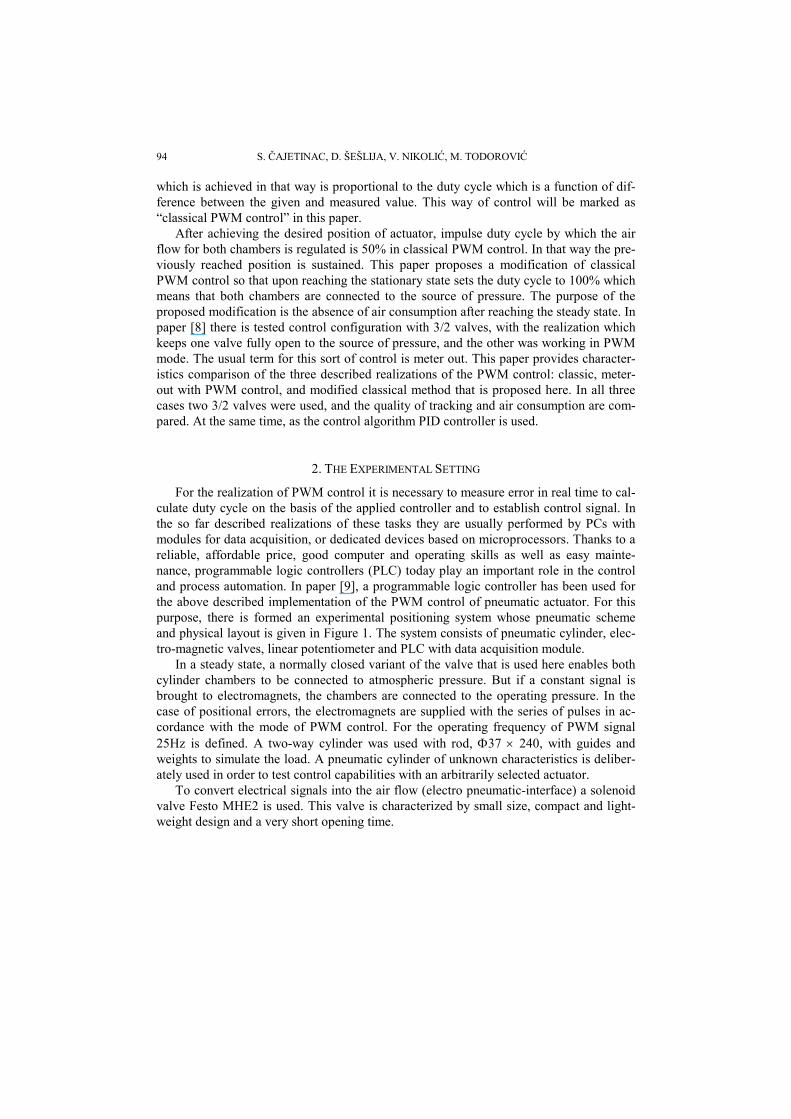
cycle. For meter-out PWM control switching is performed by only one valve, while the other one is completely open for the operating pressure. Also, no switching is done when the actuator is in the requested position. The above mentioned contributes to the system to work more quietly and with less noise. As a result, a longer lifetime of valve is expected because of its performing the fewer number of cycles.
0
10
20
30
40
50
60
70
80
90
0 1 2 3 4 5 6 7 8 9 10time (s)
po
sit
ion
(%
fu
ll s
ca
le)
actual
reference
0
20
40
60
80
100
120
0 1 2 3 4 5 6 7 8 9 10
time (s)
du
ty c
ycl
e (%
)
duty cycle 1
0
20
40
60
80
100
120
0 1 2 3 4 5 6 7 8 9 10
time (s)
du
ty c
yc
le (
%)
duty cycle 2
Fig. 4. Piston position and duty cycles in meter-out PWM control
6. COMPARISONS
The experimental system described in paragraph 2 is carried out by three described ways of control. With the same experimental setting, different control methods have been realized by various programs implemented at the PLC.
Key criteria for the comparison of the selected control are monitoring of the quality and air consumption.
Objective indicator for monitoring of the tracking quality is difference of the areas under the curve of the measured response and reference curve [11], [12], where the smallest area represents the highest quality of tracking. The most commonly used criterion is ITSE (Integral of Time Weighted Square of Error), which is defined by the relation:
dttetITSE )(2 (4)
where e(t) is error, the difference between the reference signal and the actual response of the system.
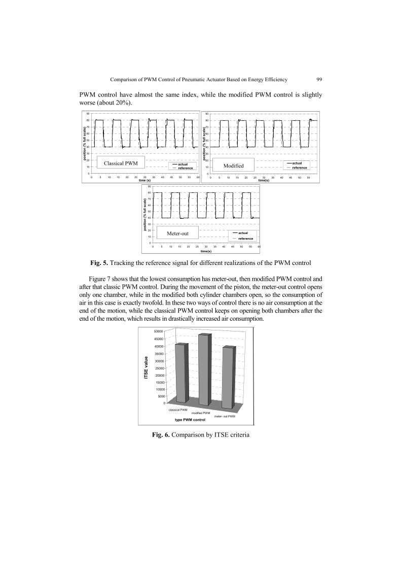
Time interval of 60s was used for comparison of the three PWM control realization. Diagrams showing the tracking of reference signal for different types of realization are given in Fig. 5. Performance index ITSE is shown in Figure 6. For the same experimental conditions and the same type of controller, it can be seen that the classical and meter-out
Comparison of PWM Control of Pneumatic Actuator Based on Energy Efficiency 99
PWM control have almost the same index, while the modified PWM control is slightly worse (about 20%).
Fig. 5. Tracking the reference signal for different realizations of the PWM control
Figure 7 shows that the lowest consumption has meter-out, then modified PWM control and after that classic PWM control. During the movement of the piston, the meter-out control opens only one chamber, while in the modified both cylinder chambers open, so the consumption of air in this case is exactly twofold. In these two ways of control there is no air consumption at the end of the motion, while the classical PWM control keeps on opening both chambers after the end of the motion, which results in drastically increased air consumption.
Fig. 6. Comparison by ITSE criteria
classical PWMmodified PWM
meter- out PWM
0
5000
10000
15000
20000
25000
30000
35000
40000
45000
50000
ITS
E v
alu
e
type PWM control
0
10
20
30
40
50
60
70
80
90
0 5 10 15 20 25 30 35 40 45 50 55time(s)
po
siti
on
(%
fu
ll sc
ale)
actual
referenceModified 0
10
20
30
40
50
60
70
80
90
0 5 10 15 20 25 30 35 40 45 50 55 60time (s)
po
siti
on
(%
fu
ll s
cale
)
actualreference
Classical PWM
0
10
20
30
40
50
60
70
80
90
0 5 10 15 20 25 30 35 40 45 50 55 60
time(s)
po
sit
ion
(%
fu
ll sc
ale
)
actual
reference
Meter-out

100 S. ČAJETINAC, D. ŠEŠLIJA, V. NIKOLIĆ, M. TODOROVIĆ
In the final choice of PWM control type it should still be considered that meter-out and modified PWM control of actuators provide quieter operation, lower noise, longer and more reliable operation of electromagnetic valve because of smaller number of activations. On the other hand, these types of control are only possible with symmetrically loaded actuators because only they can generate equal forces on both sides of the piston. Classical PWM control can be applied in cases where the piston surfaces are not equal on both sides or external force is acting on the piston. This generates different average values of pressure in the chambers, and thus the various forces on the two sides of the piston.
Air consumption of the different PWM control realizations was measured by actuator operation that had been following the reference signal during 120 s. In all three cases the source of pressure – the reservoir, was initially at the same pressure and during the operation it was not filled. The pressure was measured during operation and pressure drop results are presented in Fig. 7. Based on the initial and final pressure and known volume of the reservoir the average air mass flow rates for different types of control were calculated and the results are shown at the same figure.
Fig. 7. Pressure drop and mass flow for different PWM control realization
7. CONCLUSION
The experimental testing and comparison of three different realizations of PWM control of pneumatic actuator, with only two 3/2 valve used, are performed. The results show that classical PWM control can have a wider application, but in the view of energy efficiency it is very unsatisfactory. Therefore, its application could be recommended for small pilot valve or in cases where it is necessary due to asymmetric load of actuator. In this paper there is proposed the modification of the classical PWM control intended for the increased energy efficiency but with slightly reduced quality of trajectories tracking. However, quieter operation, lower noise and less wear of components are additional advantages of a modified classical PWM control. From the point of consumption of compressed air, the best results show meter-out realization (80.4% less consumption then classical and 50% less than modified). This shows the need for further research on the development of energy-efficient PWM control.
classical PWMmodified PWM
0,00E+00
5,00E-05
1,00E-04
1,50E-04
2,00E-04
2,50E-04
3,00E-04
3,50E-04
4,00E-04
4,50E-04
5,00E-04
mas
s fl
ow
(kg
/s)
type PWM controlmeter-out PWM
0
1
2
3
4
5
6
0 10 20 30 40 50 60 70 80 90 100 110
time (s)
pres
sure
(ba
r)
... classical PWM - modified PWM
-- meter-out PWM

Comparison of PWM Control of Pneumatic Actuator Based on Energy Efficiency 101
REFERENCES
[1] A. Messina, N. I. Giannoccaro, A. Gentile, "Experimenting and modeling the dynamics of pneumatic actuators controlled by the pulse width modulation (PWM) technique", Mechatronics 15, 2005, pp. 859–881.
[2] H. I. Ali, S. B. B Mohd Noor, S. M. Bashi, M. H. Marhaban, "A Review of Pneumatic Actuators (Modeling and Control) ", Australian Journal of Basic and Applied Sciences, 3(2): 440-454, 2009, ISSN 1991-8178.
[3] E. E. Topcu, I. Yüksel, Z. Kamıs, "Development of electro-pneumatic fast switching valve and investigation of its characteristics", Mechatronics 16, 2006, pp. 365–378
[4] G. Granosik, J. Borenstein, "Minimizing Air Consumption of Pneumatic Actuators in Mobile Robots", IEEE International Conference on Robotics and Automation, New Orleans, LA., April 26-May 1, 2004, pp. 3634-3639.
[5] D. Šešlija, I. Ignjatović, S. Dudić, B. Lagod, "Potential energy savings in compressed air systems in Serbia", African Journal of Business Control Vol. 5(14), pp. 5637-5645, 18 July, 2011, ISSN 1993-8233
[6] V. Blagojević, D. Šešlija, M. Stojiljković, "Cost effectiveness of restoring energy in execution part of pneumatic system", Journal of Scientific & Industrial Research, 2011, vol. 70 br. 2, p. 170-176
[7] R. Saidur, N.A. Rahim, M. Hasanuzzaman, "A review on compressed-air energy use and energy savings", Renewable and Sustainable Energy Reviews 14, 2010, 1135–1153
[8] J.-Y. Lai, C.-H. Menq, R. Singh, "Accurate Position Control of a Pneumatic Actuator", Journal of Dynamic Systems, Measurement, and Control, DECEMBER 1990, Vol. 112 / pp. 734-739
[9] S.Cajetinac, D.Seslija, S. Aleksandrov, M .Todorovic,“PWM Control and Identification of Frequency Characteristics of a Pneumatic Actuator using PLC controller“, The journal Electronics and Electrical Engineering, ISSN 1392-1215, September 2012, Vol. 7 (123), pp 21-26.
[10] Festo website: Fast switching valve MHE2, Available on Web site: http://www.festo.com. [11] Application Data, Procidia™ Control Solutions Digital Controller Tuning, AD353-119, Rev 1, October
2005, SIEMENS [12] Ž. Šitum, T. Žilić and M. Essert, "High Speed Solenoid Valves in Pneumatic Servo Applications",
Proceedings of the Mediterranean Conference on Control &Automation, July 27-29, 2007, Athens, Greece.