Design sensitivity analysis of non-linear structural systems part I: Theory
17
INTERNATIONAL JOURNAL FOR NUMERICAL METHODS IN ENGINEERING, VOL. 24, 2039-2055 (1 987) DESIGN SENSITIVITY ANALYSIS OF NON-LINEAR STRUCTURAL SYSTEMS PART I: THEORY* KYUNG K. CHOI AND JOSE L. T. SANTOS Department of Mechanical Engineering and Center for Computer Aided Design, College of Engineering, The University of Iowa, Iowa City, Iowa 52242. U.S.A. SUMMARY A unified approach is presented for design sensitivity analysis of non-linear structural systems that include truss, beam, plane elastic solid and plate components. Both geometric and material non-linearities are treated. Sizing design variables, such as thickness and cross-sectional areas of components of individual members and built-up structures, are considered. A distributed parameter structural design sensitivity analysis approach is used that retains the continuum elasticity formulation throughout the derivation of design sensitivity analysis results. Using this approach and an adjoint variable method, expressions for design sensitivity in terms of design variations are derived in the continuous setting which can be evaluated numerically using analysis results of finite element analysis. Both total Lagrangian and updated Lagrangian formulations in non-linear analysis of solid mechanics are used for design sensitivity analysis. Numerical implementation of design sensitivity analysis results using existing finite element code will be presented in Part I1 of this paper. 1. INTRODUCTION A reasonably complete theory of sizing and shape design sensitivity analysis for linear elastic structural systems has been developed (see References 1-3 and literature cited therein). For linear structural systems, some design sensitivity analysis methods are implemented using existing finite element Requirements on structures under severe loading conditions and increasing use of materials with non-linear properties necessitate development of design sensitivity analysis for the design of non- linear structural systems. However, the theory of design sensitivity analysis for non-linear structural systems has not been fully developed. Szefer and Demkowicz used a total Lagrangian formulation for optimal design of von Karman plates in which a minimum weight design was sought with constraints imposed on the stressg Mroz and co-workers presented a general formulation for design sensitivity analysis of geometric and material non-linear beams and plates, using a total Lagrangian formulation. They applied their theory to optimization of a,clamped- clamped beam under a uniformly distributed load." Ryu and co-workers performed a design sensitivity analysis of trusses for geometric and material non-linear behaviour using ADINA to carry out the analysis.' The subject of optimization of a flexible beam using an optimality criteria, under general boundary conditions, was addressed in a recent paper by Kamat and Mesquita.12 The purpose of this paper is to present a unified structural design sensitivity analysis method for *Research supported by NSF Project No. CEE 83-19871. The second author was partially supported by JNICT- PORTUGAL 0029-598 118711 12039-17$08.50 0 1987 by John Wiley & Sons, Ltd. Received 2 December 1986 Revised 15 June 1987
-
Upload
independent -
Category
Documents
-
view
3 -
download
0
Transcript of Design sensitivity analysis of non-linear structural systems part I: Theory

INTERNATIONAL JOURNAL FOR NUMERICAL METHODS IN ENGINEERING, VOL. 24, 2039-2055 (1 987)
DESIGN SENSITIVITY ANALYSIS OF NON-LINEAR STRUCTURAL SYSTEMS PART I: THEORY*
KYUNG K. CHOI AND JOSE L. T. SANTOS
Department of Mechanical Engineering and Center for Computer Aided Design, College of Engineering, The University of Iowa, Iowa City, Iowa 52242. U.S.A.
SUMMARY
A unified approach is presented for design sensitivity analysis of non-linear structural systems that include truss, beam, plane elastic solid and plate components. Both geometric and material non-linearities are treated. Sizing design variables, such as thickness and cross-sectional areas of components of individual members and built-up structures, are considered. A distributed parameter structural design sensitivity analysis approach is used that retains the continuum elasticity formulation throughout the derivation of design sensitivity analysis results. Using this approach and an adjoint variable method, expressions for design sensitivity in terms of design variations are derived in the continuous setting which can be evaluated numerically using analysis results of finite element analysis. Both total Lagrangian and updated Lagrangian formulations in non-linear analysis of solid mechanics are used for design sensitivity analysis. Numerical implementation of design sensitivity analysis results using existing finite element code will be presented in Part I1 of this paper.
1. INTRODUCTION
A reasonably complete theory of sizing and shape design sensitivity analysis for linear elastic structural systems has been developed (see References 1-3 and literature cited therein). For linear structural systems, some design sensitivity analysis methods are implemented using existing finite element
Requirements on structures under severe loading conditions and increasing use of materials with non-linear properties necessitate development of design sensitivity analysis for the design of non- linear structural systems. However, the theory of design sensitivity analysis for non-linear structural systems has not been fully developed. Szefer and Demkowicz used a total Lagrangian formulation for optimal design of von Karman plates in which a minimum weight design was sought with constraints imposed on the stressg Mroz and co-workers presented a general formulation for design sensitivity analysis of geometric and material non-linear beams and plates, using a total Lagrangian formulation. They applied their theory to optimization of a,clamped- clamped beam under a uniformly distributed load." Ryu and co-workers performed a design sensitivity analysis of trusses for geometric and material non-linear behaviour using ADINA to carry out the analysis.' The subject of optimization of a flexible beam using an optimality criteria, under general boundary conditions, was addressed in a recent paper by Kamat and Mesquita.12
The purpose of this paper is to present a unified structural design sensitivity analysis method for
*Research supported by NSF Project No. CEE 83-19871. The second author was partially supported by JNICT- PORTUGAL
0029-598 118711 12039-17$08.50 0 1987 by John Wiley & Sons, Ltd.
Received 2 December 1986 Revised 15 June 1987

2040 K. K. CHOI AND J. L. T. SANTOS
non-linear structural systems with sizing design variables, such as thickness and cross-sectional areas of structural components. Prototype structural components such as truss, beam, plane elastic solid and plate are used to demonstrate the method.
In non-linear structural analysis, two different approaches have been developed; the total Lagrangian and updated Lagrangian formulation^.^^-^^ In both total and updated Lagrangian formulations, equilibrium equations for the body at the final configuration are obtained in the form of incremental equations, using the principle of virtual work. These equations are then linearized around a previously known equilibrium configuration to devclop incremental formulations for analysis of non-linear problems. As noted in References 14 and 15, these two methods are analytically eq ui valen t.
These linearizations are used in this paper to obtain first variations of the governing non-linear equilibrium equations with respect to design variables, for design sensitivity analysis. Using an adjoint variable method that parallels the method presented in Rercrence 1 for linear structural systems, a linear adjoint equation is obtained for each constraint. Thc adjoint variable method gives explicit design sensitivity expressions that relate variations in structural design to measures of structural performance. Oncc structural responses of the original non-linear and linear adjoint systems are obtained, sensitivity expressions can be evaluated. If finite element analysis is used for numerical evaluation, the stiffness matrix for thc adjoint system is the tangent stiffness matrix of thc non-linear syslcm at the final equilibrium configuration.
A numerical method can be devcloped lu implement the design sensitivity results of this paper, using the versatility and convenience of existing non-linear finite element structural analysis programs, as in Rcferencc 4. As shown in Reference 4 for the linear structural systems, calculations can be carried out existing outside finite clement codes: using postprocessiiig data only.
2. INCREMENTAL EQUA‘TIONS OF NON-LINEAR ANALYSIS
Tn this section, linearizations of incremental non-linear equations, which will be used to obtain first variations of the governing non-linear equations, are introduced.
Two basic approachcs have been dcveloped in incremental non-linear finite element anaiy- sis,l 3 2 1 In the first approach. usually called the Eulerian or updatcd Lagrangian fonnulation, all structural responses are referred to an updated configuration in each load step. In the second approach, known as the total Lagrangian formulation, all structural responses are referred to the initial undeformed configuration. lliese t w o formulations have bcen devcloped and used in Referenccs 13-21.
It i s useful at this point to introduce notations that will be used.I5 A left superscript indicates the configuration lime at which the quantity occurs and a left subscript indicates the time of the reference configuration with respcct to which the quantity is measured. An exception to the notation occurs when the quantity under consideration is in the same configuration relative to which it is also measured. In this case, the left subscript need not be used. An cxampic is Cauchy stresses that arc always referred to thc configuration in which they occur c b r ~ i j = For the derivative of a quantity with rcspect to a variable, the left subscript indicates the configuration in which thc variable is considered. For example, ‘tc’;jzi,j = ?+’I According to this notation, displacements of the body a1 configuration times t and t + dl are ‘zi and i = 1,2,3, respectively. Increments in displacements from time t to tiinc t + Ar are then
zi = ‘ * * l z i - f Z j , i = 3 ( 1 )
Using thc principle of virtual work, the equilibrium equation for a body of volume ‘+*‘L‘ and surface area icnrr in the configuration at time t + At can be expressed as15

DESIGN SENSITIVLTY ANALYSIS 204 1
where fAraiJ is the Cartesian component of the Cauchy stress tensor at time t + At and + is a variation in the component of the infinitesimal strain tensor t+ateij, referred to the configuration at time t + At; i.e.
and Zi represents a variation in the current displacement component * + A f ~ i . On the right side of equation (21, '+"R represents the external virtual work done on the body by the externally applied forces, through a kinematically admissible virtual displacement Z;,
where *+A'f i and f+AfTi are components of externally applied body and surface forces, respectively. In the following development, loadings "":fi and '+*'Ti are assumed to be deformation- independent. That is, it is not rclevant in which configuration they are being evaluated.
Define the following energy from:
and load form l(5) ZE t+*'R
Then the equilibrium equation of equation (2) can be rcwritten as
(7) ~ ( ~ + * ' z , z ) = l ( ~ ) , for all ZEZ
where Z is the space of kinematically admissible virtual displacements. Equation (2) or (7) cannot be solved directly, since the configuration at time t + At is unknown. A
solution can be obtained by referring all variablcs to a known previously calculated equilibrium configuration. In practice, two different formulations are used: the updated Lagrangian formulation and the total Lagrangian formulation.' 3-21
Updated Lagrangian formulation
In the updated Lagrangian formulation, all variables of equations (2) and (4) are referred to the updated configuration of the body at time t. In this formulation, equation (2) (or cquation (7)) is transformed
?+
= JCv "A~,fl,5,tdV + Jtrt+*:TLtil*dI- = l(rF), for all t i ~ , Z (8)
where ,Z and '+*:S,, are the space of kinematically admissible virtual displacements and the Cartesian component of the 2nd Piola-Kirchhoff stress tensor at the configuration at time t + At, measured with respect to the configuration at time 1, respectively, and is a variation of the
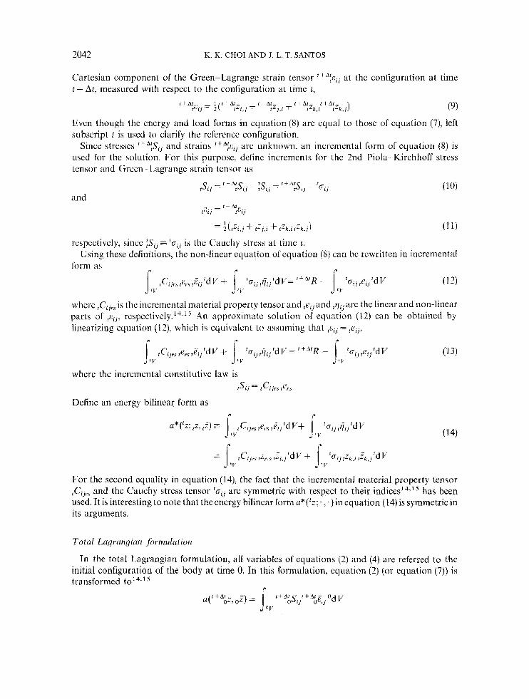
2042 K. K. CHOI AND J. L. T. SANTOS
Cartesian component of the Green-Lagrange strain tensor ' + * : E , ~ a t the configuration at time l + At, measured with respcct to the configuration at timc t ,
*+h:ZJ.l + t + A f Z k , l t + * ; Z L < j ) (9) ?EIJ = +('+*:Z1 + z+Af
Even though the energy a i d load forms in equation (8) are equal to those of equation (7), Mt subscript t is used to clarify the reference configuration.
Since stresses ItA;SIJ and strains t + A : ~ l J are unknown. an incremental form of equation (8) is used for the solution. For this purpose. define increments for the 2nd Piola Kirchhoff stress tensor and Green Lagrange strain tensor as
and
(1 1) -1 - Z ( z 7 i . j + tzj,i + t Z k , i * = , c . j !
respectively, since :Si j = 'ui,; is the Cauchy stress at time t.
form as Using these definitions, the non-linear equ.ation of equation (8) can bc rcwrittcn in incremental
rCiJrs r ~ , , s & 'd V + 'cr.. t j . . 'dV= ""R - 'G.. l l f 2. 1.1 .'d V (12) Irv 1 1 t v I t v
where rCijrs is the incremental material property tensor and ,eij and *qij are the linear and non-linear parts of J ~ , , , re~pectivcly. '~. '~ .An approximate solution of equation (12) can be obtained by linearizing equation (12); which is equivaicnt to assuming that = tqj2
lIV (1 3 )
where the incremental constitutive law is tSi,j = rCi j r s rers
Define an energy bilinear form as c
r r
For the second equality in equation (141, the fact that lhc incremental material property tensor tCIJrs and the Cauchy stress tensor 'oy arc symmetric with respect to their indices14.15 has been used. It is interesting to note that the energy bilinear form u*( ' z ; . , . ) in cquation (14) is symmetric in its arguments.
Totul Lugrcirzyiun jhmulution
In the total Lagrangian formulation, all variables of equations (2) and (4) are referred to the initial configuration of the body at time 0. In this formulation, cquation (2) (or cquation (7)) is transformed to'4.' '
$) = jov t+AhS,J'+A&Cl, OdV

DESIGN SENSITIVITY ANALYSIS 2043
r P
where O Z and f+ALSij arc the space for kinematically admissible virtual displacements and the Cartesian component of the 2nd Piola-Kirchhoff stress tensor at the configuration at lime t + At, measured with respect to thc configuration at time 0, respeclively, and is a variation of the Cartcsian cornponcnt of the Green-Lagrange strain tensor t fA&ij at the configuration at time t t- At, measured with respect to the configuration at time 0,
(16)
As in the updated Lagrangian formulation. even though the energy and load forms in equation ( 1 5 ) are equal to those equations (7) and (8), left subscript 0 is used to clarify the reference configuration. ' are unknown, an incremental form of equation (15) is used for the solution. As in thc updated Lagrangian formulation case, define increments for the 2nd Piola-Kirchhoff stress tensor and Green-Lagrange strain tensor as
i t A t E , , = l . ( t + A f Z . , + L t A r t -t A1 0 z,; 2 0 1.1 ()ZJ.i + f+A;zk.i oZ,,i)
Since stresses L+A&'jj,i and strains
"Si j = t + A f l J L I I 7.. - 0 ' S i j (1 7 ) and
respectively. A variation of thc Green Lagrangc strain tensor is
since '2, = 0 gives
form as
= 0 Using thesc definitions, thc non-linear equdtion of equation ( 15) can be rewritten in incremental
(,CIJ',,,~,,O~~!'llcrdl' + (;'it, ( , G l j " d V = tA"'R -- ;St,,,e,,'db' (20) v r ' 1 "L . r
where OCIJrT i b t he incremental material property tensor and o~~~~ and oql , arc the line'ir and non- linear parts of "L,,. respectively '' ' ' An approximate solution of equation (20, can be obtained by Linearimg equation 120). which 19 equivalent to ummp that "tZl = oe,,,
r r r
where thc incremental constitutibe la& is
As in the updated 1,agrangian formulation, iicfine mothcr energy bilinear form as

2044 K. X. CHOI AND J . L. T. SANTOS
The fact that the incremental material property tensor &,, and the 2nd Piola-Kirchhoff stress tensor &S,, are symmetric with respect to their indicesl4,I5 has been used for the second equality in equation (22). Thus, the energy bilinear form a*(&;,.) in equation (22) is symmetric in its arguments.
Both the updated and total Lagrangian formulations include large displacements, large rotations, large strains and material non-linearities, when appropriate kinematic and constitutive descriptions are
3. ADJOINT VARIABLE METHOD OF DESIGN SENSITIVITY ANALYSIS
An adjoint variable method for design sensitivity analysis that is similar to the method presented in Reference 1 for linear structural systems is developed in this section to obtain design sensitivity expressions of general functionals in terms of perturbations of design. An expected and yet interesting fact is that the adjoint equation is linear.
3.1. Dgerentiability of energy and load ,forms and static response
The theory of design differentiability of non-linear structural response has not been developed in the literature, whereas a reasonably complete theory on differentiability of linear structural response is given in Reference 1. Since the theory of non-linear structural design sensitivity analysis is not as well developed as that for linear structural systems, a more formal treatment is presented in this section.
Consider a structural system in its final equilibrium configuration. at time t (instead of t + At of Section 21, corresponding to a given design u. The equilibrium equation for the structural system can be written, using equation (7),
a,,('z, 2) = l r L ( F ) , for all FEZ (23) where the subscript u is uscd to indicatc that the equihbrium cquation corresponds to the design u. Suppose that the design is perturbed by z du. As a consequence, there is a change in response of the sybtem and a new equilibrium configuration occurs at time i +At. The new equation of equilibrium is
a,, + r d u ( f + 4f 2, 5) = I,, + c8,,(f), for all Z E % (24) Note that At -+ 0 a s z -+ 0.
For design sensitivity analysis, the variations in measures of structural performancc due to the variations in design havc to be found. This information can be obtained by taking the first variation of equation (24) with respect to design 11. For this purpobe, it is convenieni to use cquations (8) and (1 5 ) for the updatcd and total Lagrangian formulations. respectively.
Upduted Luyrnnqiutz #ormulation. Using equation (81, the equilibrium equation of the structural system at its final configuration time t + At, corresponding to the perturbed designu 1- z 6u, with reference configuration at time t , can be written as

DESIGN SENSITIVITY ANALYSIS 2045
Define the first variation of the non-linear energy form of equation (25), with respect to its explicit dependence on the design variable u, as
where 'Zdenotes the state '2, with dependence on z suppressed, and ,?is independent of z. The prime notation in equation (26) represents the first variation of a, with respect to the explicit dependence on design u. The first variation of the load form of equation (25) is defined as
Now define the first variation of the solution of equation (25) with respect to the design as
Using the above definition, it can be noted that the order of taking the first variation and the partial derivative of the state can be interchanged; i.e.
( t Z , j ) ' z= ( t 4 ) , j (29) where the partial derivative should be taken with respect to variables in the configuration at time t .
Using the chain rule of differentiation and equations (26) and (28),
t t A t d $,+rdu( *z(u + r 6 4 , tall,=*
= II;,(rZ, ,Z) + a?('z; rZ', *?) (30) For the second term on the right of equation (30), the linearization process from equation (8) to equation (14) has been used. By taking the first variation of both sides of equation (25), using equations (27) and ( 2 8 )
and, from equation ( 1 4), a:('z; (z', tZ ) = - ~: , ( f z , J) , for all t Z ~ , Z (31)
Presuming that the state ' z is known as the solution of equation (23), using the updated Lagrangian formulation, equation (31) is a variational equation for the first variation p'. Thus, if a direction 6u of design change has been selected, equation (31) may be solved to obtain $. Construction of such a solution depends on 6u, however, since Su appears on the right of equation (31).
Total Lagrangian ,formulation. Using equation (15), the equation of cquilibriurn of the structural system at its final configuration time t + At, corresponding to the perturbed design u + T ~ U , with reference configuration at time 0, can be written as
U ~ + ~ ~ , , ( ' + ~ ~ Z , = l u + r 6 i r ( 0 ~ ) for all ,ZE,Z (33)

2046 K . K. CIIOI AND J. L. T. SANTOS
Define the first variation of the non-linear energy form of equation (33). with respect to its explicit dependence on the design variable u. as
(34) r - - d d t oT) = -- 4 t r6u(0Z, o=)lr=o
where 0'2 denotes the state :z, with dependence on z suppressed, and t. The first variation of the load form of equation (33) uith respect to design u is defined as
is independent of
Define the variation of the solution of equation (33) with respect to design ii as
t + o t
As in the updated Lagrangjan formulation, the order of taking the first variation and the partial derivative of the state can be interchanged; i.e.
(0Zi.j)' = ( & ) . , j (37)
where the partial derivative should be takcn with respect to variables in the undeformed configuration at time 0.
The chain rule of differentiation and equations (34) and (36) yield
= Ll;u(;z, ,)Z) + a:((;:; ()3', " 2 ) (38)
For the second term on the right of equation (38), the lineariaation process from equation (1 5) to equation (22) has been used. By taking the first variation of both sides of equation (33) and using equations ( 3 s ) and (36),
~r,T(dz: ,$, ,,:) = /:),(,,z) asu(& 0) for all O f ~ , , % (39)
and, from equation (22), r
As in the updated Lagrangian formulation, presuming that the state is known as the solution of equation (23) using the total Lagrangian formulation, equation (39) is a variational equation for the first variation ,,z'. The solution r l ~ ' of equation (39) depends on du, since the right side of equation (401 depends on du.
As mentioned in Section 2: since both the updated and total Lagrangian formulations include large displacements, large rotations, large strains and matcrial non-linearities when appropriate kinematic and constitutive descriptions are used, results of this section are valid for those cases.

DESIGN SENSITIVITY ANALYSIS 2047
3.2. iidjoint variable design sensitiuity anulysis
formulations. In this section, only infinitesimal strains arc considcrcd. Design sensitivity analyses are carried out for both the updated and total Lagrangiaii
Updatcd Lagvangian formulariorz. Consider a measure of structural performance that can be written in integral form at the final equilibrium configuration time 1 + At- corresponding to the perturbed design t t + z du, a5
I - \ I p ~ ~ ( t + " ~ . t + ~ f V ' + A i ~ , ~ ~ + ~ ~ ~ ) ~ + A . f d V (41) where
0' + s 1 4 V t t A t - = [ v h A f _ v i + A t z
i + A t - ' - 1 1 - l , f + A l Z i t + A r
The functional of equation (41) depends on the design in tuo u d y i hirit the intcgrand q(,+"z, , + f f V f + A f z . u + s 6 u ) depend7 on the de\ign. 4 1 ~ . thc domain of integration depends on the design Thus, t o obtain sensitibity information, a concept similar to material derivative' must be used. Hohever, h c e only infinitesimal strains arc considcrcd. the determinant of the deformation gradient r + ' ~ J = ( r V f + A t ~ r ) l can be assumed to be equal to one. Thus, dependence of the functional on design occurs through the integrand y only.
Taking the variation of the functional of equation (41) with respect to design vanables,
Eeibnitz's rule may be rule of dilkrcntiation.
used to take the derivative of thc intcgrand of cquation (42) and thc chain together with equations (28) and (29)- yields
,-
(43)
where
An explicit expression for ' 1 ) ' is desired in tcrins of bu. which requires rewritting the first two terms of the integrand olequation (43) explicitly in terms of 6u. Introduce an adjoint equation, in thc same manner as in Reference I , h y replacing r ~ ' in equation (43) by a virtual displaceineiit ,. and equating tcrms involving in equation (43) to the energy bilinear form a,* ( ' q t L t J ) defined in equation (141. yielding the adjoint equation for the adjoint variable tJL as
~-
a : ( f z ; f i , l j . ) = ( g , = , x + q,t . , ,V~)fdV, for a11 ,&,Z (44) JLII ...
where a solution J is desired. Evaluate equation (44) a t = since $E,Z, to obtain
u: (fz: 1, l, (gtz ' + (/'vtz (VZ') 'd I.' (45)
which are just terms of equation (43): to be written explicitly in terins of bzr. Similarly, evaluate equation (31) at = J,, since both are in J, to obtain
a:(':; [ z ' ~ $") = />,d(J) ~- a&(':. ,i) (46) Recalling that thc ciicrgy bilinear form U ; ( ~ Z , . ~. ) is symmetric in its arguments, the left sides

2048 K. K. CHOI A N D J. L. T. SANTOS
of equations (45) and (46) are equal, thus yielding the desired results
where the right side is linear in 6u and can be evaluated once thc state ‘ z and the adjoint variable J are determined as the solutions of equation (23), with the updated Lagrangian formulation and equation (43), respectively. Substituting this result into equation (43), the explicit design sensitivity expression is
where the form of the last two terms on the right depends on the structural component under investigation. Explicit expressions of these two terms are given in Section 4 for some prototype structural components. Equation (48) will serve as the principal tool for design sensitivity analysis of non-linear structural systems with large displacements, large rotations, small strains and non-linear elastic material properties.
An expected and yet interesting fact is that, even though the original governing equation is non-linear, equation (44) is linear. ‘Phis means that effort in computation of sensitivity will be the same for both linear and non-linear structural systems.’,4 If finite element analysis is used for numerical analysis, the stiffness matrix of equation (44) is thc tangent stiffness matrix at the final equilibrium configuration.
Total Lagranyian jwmulution. Consider a measure of structural performance that can be written in integral form, at the final equilibrium configuration time 1 + At with reference configuration at time 0,
r
where ~V‘+*‘Z = [OVfiAtZ1, g V f + A ‘ ~ 2 , g V f + 4 i l t ~ 3 1
Taking the variation of the functional of equation (49) with respect to design,
By the same method as in the updated Lagrangian formulation, introduce an adjoint equation by replacing 02‘ in equation (50) by a virtual displacement ,I and equating terms involving O X in equation (50) to the energy bilinear form u , * ( ; ~ ; ~ i , ~ ~ ) defined in equation (22), yielding the adjoint equation for the adjoint variable $”,
- a,*(&; O)v,OZ) = loV (gd2 O R + govtz oVT) ‘dV, for all JE~Z (51)

DESIGN SENSITIVITY ANALYSIS 2049
where a solution oA is desired. Since O ~ ' ~ o Z , evaluate equation (51) at ,x= o ~ ' to obtain
a,*(& O i , o f ) = jov (s;, o f + Y0vtz OVZ') OdV
Since and olv are in ,Z, evaluate equation (39) at oZ = oi to obtain
a,*(dz; 02'2 0 4 = L ( o 4 - a;&, 0)") (53)
Using symmetry of the energy bilinear form a,T(:z;*;) in its arguments,
j0" (g;- OZ! + sovtz OVZ') OdV = M o 4 - a&,(& 0 4 (54)
where the right side is linear in 6u and can be evaluated once the state dz and the adjoint variable ,,i, are determined as solutions of equation (23) with total Lagrangian formulation and equation (51), respectively. Substituting this result in equation (50),
it,!/' = gu 6~ OdV + I;,(oA) - a&(iz, oi) (55 ) lo" which expresses the dcpendence of design sensitivity on the design variation and the form of the last two terms on the right depends on the problem under investigation. Exactly the same remarks given to the sensitivity result of equation (48), obtained using updated Lagrangian formulation, are applicable to the result of equation (55).
4. ANALYTICAL EXAMPLES OF STATIC DESIGN SENSITIVITY
The general results presented in Section 3 are applied to truss, beam, plane elastic solid and plate components to calculate design sensitivity formulae. In this section, the updatcd Lagrangian formulation is used. since it yields physically meaningful Cauchy stress tensors, instead of 2nd Piola-Kirchhoff stress tensors, which are used in the total Lagrangian formulation. Once this is done. extension to the total Lagrangian formulation can be done easily. For simplicity. in this section, examples are given for linear clastic material with large displacements, large rotations and small strains. In the formulation, truss and beam components are incorporated into a single component. Similarly, plate and plane elastic solid components are combincd as a single component.
Bemn/tru.ss
Consider the beam:'truss component of Figurc 1, with design variable u = A ( x , ) as the cross-sectional area of the beamhruss. The energy form of the component isz2

2050 K. K CHOI AND J 1. T‘. SANTOS
where ‘z1, ‘zZ, and tz3 are axial displacement and two orthogonal lateral displacements, respectively, and ‘z = [‘zl. ‘z2, In equation (56), E. I’ and I 3 are Young’s modulus and two moments of inertia, respectively, and ‘1 is the arc length of the centroidal axis of beam/truss component at the cquilibrium configuration corresponding to the design u. The load form for the component is
/,,(?) = ‘flZ, ‘dxl (57) $1 where ‘fl, ‘ j 2 and y3 are axial load and two orthogonal lateral loads, respectively, as shown in Figure 7. If there are point loads, a Dirac measure can be used in equation (57).’
Calculating variations of the energy and load forms from equations (261 and (27).
and
where yt is assumed to be a function of A te.g. self-weight).
first a functional that defines the value of displacenicnt ,zt an isolated point Sevcral alternative forms may now be considered for structural response functionals. Consider
i s .
- ‘ ? l ) 5 ( l X l ) ‘ d x l
where &,) I S the Dirac measure at the origin. The variation of thc functional 15
- r , ? l ) t ~ (Ix1)ldyl
The adjoint equation of cquation (44), in this case. IS
-
- f ? l ) l / T ‘ d ~ l , for dll ,r*.t,L (62) J
Interpreting the Dirac measure as a unit load applied at point ph)cical interpretation of

DESIGN SENSITIVITY ANALYSTS 205 1
is obtained as the displacement of thc beam/truss from the final equilibrium configuration at time t due to a unit load at lR1 in the direction of 'z('.tl). This interpretation agrees with the fact that the stiffness matrix of the adjoint equation is the tangent stiffness matrix at the final equilibrium configuration.
Using equation (48), the design sensitivity expression is
V' 1 - - 1' d u L 4 - aBU"Z, tjL) (63)
where equations (58) and (59) can be used for the explicit expressions on thc right of equation (63) with J the solution of equation (62).
Another important functional that arises in design of beam/truss component is stress,
where x A ' ! ~ and PA1'' are half-depth of the beam in the 'x2- and 'x3-directions, respectively, and mp(fx1 ) is a characteristic function that is non-zcro only on a small subinterval and whose integral is 1. The expression in cquation (64) gives the average value of stress over the subinterval.' Variation of the functional of equation (64) yields
'tj/L = E(?z;. , - ' z ~ , ~ t ~ i , l + CZA~!~,Z;,,~ + ~ ~ 4 i ' 2 t ~ j , , 1 ) ~ ~ , ' d ~ , SE The adjoint equation or cquation (44) is, in this case,
- u:(5;f j+, , jb) = E ( t i l . , - t ~ L , , r/.r ,
- 5:: -
IJsing equation (481, the design sensitivity expression is
nhere, as in the displacement functional case. equations ( 5 8 ) and (59) can bc u d for explicit expressions ofthe last t no term5 on the right ofequation (67) nith &. the colution ofequation (66).
Piute/pinne eluvtic 5 0 1 1 r l
is the thickness of the platc'planc clasiic solid T h e energy form for thic component Connder the plate plane e1:istic solid component of Figurc 3. The design variable u = h ( i , . x 2 )
+2(1 - - \ ~ ~ f - 7 3 , 1 2 r ~ j ,,]'dSt (68)
' z L and L ~ I arc ciisplaccnicnts oftbc middle surface and latcral displaccmcnt> respeciively, where
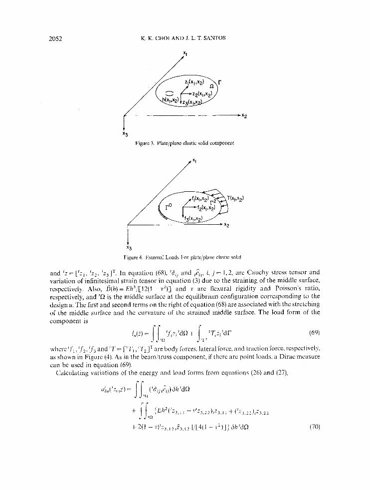
2052 K. K. CHOI AND J. L. T. SANTOS
Figure 3. Plate/planc elastic solid component
x3
Figure 4. External Loads For plate/plane elastic solid
and ‘z = [ ‘ z , , ‘ z2 , ‘ ~ ~ 1 ’ . In equation (6x1, ‘Aii and :Zij, i. , j = 1,2, arc Cauchy stress tensor and variation of infinitesimal strain tensor in equation ( 3 ) due to the straining of the middle surface, respectively. Also, 8(h) = Eh”[ l2(1 ~- v’)] and v are flexural rigidity and Poisson’s ratio, respectively, and ‘Q is the middle surface at the equilibrium configuration corrcsponding to the design u. The first and second terms on the right of equation (68) are associated with the stretching of the middle surface and the curvature of the strained middle surface. The load form of the component is
[ J F ) = [j ! f i .F j ‘dO + ‘Ti3,‘dT (691
whcre Ifi, if,. f f3 and ‘T = L r I’, *TJ I are body forces, lateral force. and traction force, respectively, as shown in Figure (4). As in the beanytruss component, if there are point loads, a Dirac measure can be used in equation (69).
‘I! jcl.2
Calculating variations of the energy and load forms froin cquations (26) and (27),

DESIGN SENSITIVITY ANALYSIS 2053
and
where 'fj is assumed to be a function of h (e.g. self-weight). Consider first a functional that defines the values of the displacement at a point '2 = (Y,, '&),
r r
where $(('x) is the Dirac measure at the origin. The variation of the functional is r r
= J J 8('x - 'R),z'(tx)'dQ 'R
As in the beam/truss component, the adjoint equation of equation (44) is r r
(73)
The adjoint load form on the right of equation(74) is due to a unit load applied at '2 in the direction of ' z ( ' i ) . Using equation (48) the design sensitivity expression is
= MI4 - aB,('z, I 4 (75)
where equations (70) and(71) can be used for explicit expressions on the right of equation (75) with & the solution of equation (74).
Next, consider a stress functional that is associatcd with the strength ofthe plate/plane elastic solid component,
I r r
where rnP('x) is a characteristic function that is non-zero only on a small subdomain and whose integral is 1 . ' The first and second terms on the right of equation (76) are the average normal stresses in the x,-direction due to straining of the middle surface and curvature of the strained middle surface, respectively. Variation of the functional of equation (76) yields
1 t r $4=FvzjJJ tQE[( tZi .1 - 'z~,1tz: ,1)+V(tz; ,2 - * Z ~ , 2 ~ . ~ ) 1 r n p t d ~
The adjoint equation of equation (44) is, in this case,

2054 K. K. CHOl AND J. L. T. SANTOS
Using equation (48) the design sensitivity expression is
+ l&L) - Uk,(:i,tL) (79)
where, as in the displacement functional case, equations (70) and (71) can be used for explicit expressions of the last two terms on the right of equation (79) with tiw the solution of equation (78).
5. BUILT-UP STRUCTURES
In this section. design sensitivity analysis of non-linear built-up structures is presented, using the updated Lagrangiaa formulation and a design component method that parallels the method presented in Reference 23 for linear built-up structures.
Consider a built-up structurc that is made up of m > 1 structural components that are interconnected by kinematic constraints at their interfaces. Using the principle of virtual work for built-up structures, thc variational formulation of the governing equations is
Li,('z, F) = l z , ( i ) , for all ~ E Z (80) where
and Z is the space or kinematically admissible virtual displacements, which is defined as the set of dispiacement fields that satisfy homogenous boundary conditions and kinematic interface conditions between components. In equations (81) and (82), u,,~(*z, F) and l , L j ( F ) are the energy and load forms for components i . Note from equations (81) and (82) that the energy and load forms of equation (80) arc simply summations of corrcsponding terms from each component. Thus; as will bc seen later, design sensitivity analysis of the built-up structure is a simple additive process. The first variation of equation (80) is
(83) where =
In this section, design sensitivity information for a displacement functional is derived for general built-up structurcs. Once this is done, extension to locally averaged stress functionals can be carried out easily. Consider a displaccmeut functional that defines displacement at an isolated point YE~W,
u,T('-; $, rZ) = lb,('z, r: ), for all , ~ E , Z
, p i , tz'JT for both beamltruss and platejplane elastic solid components.
'4) = 'z(',?) = {jLQ, 6( 'u 'Q)'z('x)'dR
where '!2 is the rth structural component. Taking the first variation of equation (84).

DESIGN SENSITIVITY ANALYSIS 2055
The adjoint equation is -
U ~ ( ~ Z ; , ~ ~ , ~ ~ . ) = {{tQ,8(‘x - ‘?),X‘ddR. for all , ~ E ~ Z
As before, denote the solution of equation (86) as ti.. Using the adjoint variable method,
Notc that equation (87) is valid for general built-up structures that are composed of W I 3 1 structural components. For explicit expressions of ternis on the right of equation (87), results of equations (58),(59),(70) and (71) can bc used for each structmal componenl.
REFERENCES
1. E. J. Haug, K. K. Choi and \I. Komkov, Design S m s rg Andysis qf Strucmrnl Systenzs, Academic Press, New York. 1986.
2. H, M. Adelman and R. T. Haftka, ’Sensitivity analysis for discrete structural systems ~~ a survey, N A S A T,2.1-86333, December 1984.
3. R. 2. Haftka and R . V. Grandhi, ‘Structural shape optimimtion-a survey’. Comp. i l e t i ~ o d s Appl. Mech. En<{., 57. 91--106 (19x6).
4. K. K. Choi, J . L, T. Saiitos and M. C. Frederick, ‘Implemcntation of desipn sensitivity analysis with existing finite element codes’. A S V K J . Meleck., Tran.\n~is.sions, Automcrlion in Desjgn, to appear I 1987).
5. ‘B. Prasaci and J. F. Emerson, ’General capability of design sensitivity lor finite clcnicnt system’. .~IAA:ASIZIIE~AHS 23rd Sjruclures, Structural Dynninica. and Materials Co,$erence. Part 2. A I A A 90. SZ-06KO pp. 175 -186.
6. G. L. Giles. and J. L. Kogers, JT., ‘Implemcntation of structural rcsponse sensitivity calculations in a large-scale finite element analysis system’, A IA.4:’ASME:’ASCL:iAHS Z3rd Struclures. S t ~ w r r r m l Dyr/u!nic.$ imd Materials Conference. Purl 2, A I A A No. 82-0714, 1982, pp. 34-35’),
7. D. V. Wallcrstein. ‘Design enhancement tools in MSC;NASTRAN’. Krtent Expwic!tces i n Alultidistipiinnr~ Analysis and Oprimizution. N A S A CP -7337. 1984, pp. 505-526.
8. B. Dopker and K. K. Choi. ’Si7ing and shape design sensitivity analysis using a hybrid linite element code’. Finile Elenterits A d I k l z i g r i , to appear (19871.
9. ti. Szefer and L. Ihiibowicz, ‘Optimal design of Von Karman plates’. J . SzrucI. Mech., 12, 11 1 - ~ 149 (1984). 10. 2. Mroz, hl. P. Kamat and R. H. Plaut, ‘Sensitivity analysis and optimal deslgn of nonlinear beams and plates’. J .
11 . Y. S. Ryu. M. Haririan, C. C. Wu and J. S. ,4rora, ‘Structural design sensitivity analysis of nonlinear responyc’, Chnp.
12. M. P. Kamat and L. Mesqtiita, ‘Optimization of highly flexible beams‘, Eny. O p t i v ~ i i ~ ~ l i ~ ~ 9, 61-72 (1985). 13. K. D. Cook, Concept und Appliccirion o f ’ t h e kin i i r EI~nierzl Annly, is, Wiley, Nefi York. 19x1. 14. K. J. Bathe. Fivite E/MZCJU Procedu,cs in Enqinrering Aricdysis, Prentice-Hall. Englewood Cliff?. N.J.. ! 982. 15. K. J . Bathe, E. Rarnm and E. L. Wilson. ‘Finite clement formulations for large dekxination dynamic analysis’. Int. j .
I I I I I ~ Z ~ Y . nwrhno‘s ~ n g . , 9, 353 386 (1975). 16. S. Yagmai. ’Incremental analysis of large deformations in mechanics of solids with apphcations to axissymctric shells ol’
rcvulution’. 1’11.1). Disser~til i~ii i , Department of C:i\il Fngineering, linivc:sity of California. S K S M X e p r l 68-1 7, 196X: also piiblished as M A S A C. ’o~~rruc~cr Report 1350. 1969.
17. J. A. Strictlin. W. A. Von Rieaemann. J. R. Tillerson and W. E. Haislcr, ’Static geometric and material nonlinear analysis‘, /Id~.mcc.s in Compiriulioriol Merhor2,- i n Srruclurul M c ~ h r r m rind L)c.siyn, IJniversity of Alahama Press, 1972, pp. 302 ~ 324.
18. H. D. Hibbitt, P. V. MarcaI and J. K. Ricc. ‘A finite elemciTt forniulaiion for problems of largc strain and large displacement’, 1111. J. Solids
10. G. 4. Dupuis, H. D. Hibbitt arcal. ‘Nonlinear materid and geometric bchaviour of shell slructures’. Cornp. Strixi.. 1
20. 1’. Y amada. ‘Incremental formulations Tor problems with geometric and material nonlinearilics’, Adzcinces in Cornputdovial Melhods iw Struclurd Mcchmtics iu7d Design, University of Alabatna Press, 1972. pp. 325--35S.
21. 5. T. Oden, Finire E I m t w & 0/ X m d j n m C‘unlinua, McGraw-Hill, Ncw Y ork, 1972. 22. V. 1’. Novozhilov. Foundarinns of rhe h‘oniinem Theory of Eloyricirj. Graylock Press. Rochester, Ncv. Yorh. 1953. 23. K. K . Choi and M. C;. Seong, ‘Design componcnt niethod for- sensitivity analysis of built-up structures’., J . Strucr. ,Mrch..
Struci. Mech.. 13, 245-266 (1985).
Strurr., 21, 2455255 (19x5).
14, 379 399 (19x61.