Flexural capacity and stiffness of monolithic biaxial hollow slabs
Upload
khangminh22Category
view
2download
0
Citation: Castelli, F.; Grasso, S.;
Lentini, V.; Sammito, M.S.V. Design
of a Biaxial Laminar Shear Box for 1g
Shaking Table Tests. Geotechnics 2022,
2, 467–487. https://doi.org/
10.3390/geotechnics2020023
Academic Editors: Qi Wang,
Bei Jiang, Xuezhen Wu and
Hongke Gao
Received: 26 April 2022
Accepted: 10 June 2022
Published: 16 June 2022
Publisher’s Note: MDPI stays neutral
with regard to jurisdictional claims in
published maps and institutional affil-
iations.
Copyright: © 2022 by the authors.
Licensee MDPI, Basel, Switzerland.
This article is an open access article
distributed under the terms and
conditions of the Creative Commons
Attribution (CC BY) license (https://
creativecommons.org/licenses/by/
4.0/).
Article
Design of a Biaxial Laminar Shear Box for 1g ShakingTable TestsFrancesco Castelli 1 , Salvatore Grasso 2 , Valentina Lentini 1 and Maria Stella Vanessa Sammito 2,*
1 Faculty of Engineering and Architecture, University “Kore” of Enna, 94100 Enna, Italy;[email protected] (F.C.); [email protected] (V.L.)
2 Department of Civil Engineering and Architecture, University of Catania, 95123 Catania, Italy;[email protected]
* Correspondence: [email protected]
Abstract: In this paper, the design of a new laminar shear box at the Laboratory of EarthquakeEngineering and Dynamic Analysis (L.E.D.A.) of the University of Enna “Kore” (Sicily, Italy), ispresented. The laminar box has been developed to investigate the liquefaction phenomenon andto validate advanced numerical models and/or the numerical approaches assessed to simulate andprevent related effects. The first part of the paper describes in detail the types of soil containers thathave been used in the last three decades around the world. Particular attention is paid to laminarshear box and liquefaction studies. Moreover, the most important factors that affect the performanceof a laminar shear box are reported. The last part of the paper describes components, properties,and design advantages of the new laminar shear box for 1g shaking table tests at L.E.D.A. The newlaminar box has a rectangular cross section and consists of 16 layers. Each layer is composed of twoframes: an inner frame and an outer frame. The inner frame has an internal dimension of 2570 mmby 2310 mm, while the outer frame has an internal dimension of 2700 mm by 2770 mm. Between thelayers, there is a 20 mm gap, making the total height 1600 mm.
Keywords: liquefaction; 1g shaking table test; laminar shear box
1. Introduction
Liquefaction is one of the major reasons for damage during an earthquake [1]. Thephenomenon occurs as a result of build-up of pore pressure and hence a reduction ofsoil strength [2]. A better understanding of this phenomenon is of relevant interest ingeotechnical earthquake engineering.
Liquefaction studies involve several approaches and procedures: laboratory cyclictriaxial tests [3–5], stress-based simplified procedures [6–12], numerical models [1,13–15],dynamic element tests [16,17], reduced-scale model tests [18–20], and full-scale fieldtests [21–23].
Reduced-scale model tests are advantageous for seismic studies thanks to the abilityto provide economic and realistic information about the ground amplification, change inwater pressure, and soil non-linearity [18,24].
This paper presents the design of a biaxial laminar shear box for reduced-scale modeltests. The laminar shear box can be used in liquefaction studies, especially to validatenumerical models and/or the numerical approaches assessed to prevent related effects.
The numerical simulation of soil lab tests is relevant to qualitatively understand thebehavior of the “artificial soil” and should therefore be considered in the validation process.
2. Background
Geotechnical scaled seismic model tests can be divided into two categories: shakingtable test at 1g and centrifuge test at n-g [1,24–27]. Shaking table tests have the advantagesof well controlled large amplitude, and easier experimental measurements than centrifuge
Geotechnics 2022, 2, 467–487. https://doi.org/10.3390/geotechnics2020023 https://www.mdpi.com/journal/geotechnics

Geotechnics 2022, 2 468
tests. However, high gravitational stresses cannot be produced to faithfully simulate fieldconditions [18,20,25,26,28–30].
Most studies of seismic soil behaviours were for one-dimensional shaking [24,26,27,31–35].However, real earthquake excitations are multiaxial [36]. Ng et al. [37] performed biaxialshaking centrifuge tests to investigate the response of saturated embankments. Uenget al. [38] developed a large flexible laminar shear box for the study of the behaviour of sat-urated sand under two-dimensional earthquake shaking. Zeghal et al. [36] investigated thedynamic response and liquefaction of saturated sand deposits subjected to biaxial shaking.
A variety of model container configurations have been used in the last three decades.Six types of soil container can be identified: rigid, rigid with flexible boundaries, 1rigid withhinged end-wall, equivalent shear beam (EBS), laminar, and active boundary container [29].
The simplest method for geotechnical modelling is to use a rigid box. In this design,the shear stiffness of the end wall is much higher that the stiffness of the layers of soilcontained in it [29]. Sadrekarimi & Ghalandarzadeh [2] performed 1g shaking table testsusing a transparent plexiglas container to study liquefaction mitigation methods.
Motamed & Towhata [39] used a rigid container with transparent side walls tostudy the seismic performance of pile groups behind quay walls subjected to liquefac-tion (Figure 1). Özener et al. [40] investigated the liquefaction behaviour of layered sandsusing a cylindrical Plexiglas container (Figure 2).
Geotechnics 2022, 2, FOR PEER REVIEW 2
2. Background Geotechnical scaled seismic model tests can be divided into two categories: shaking
table test at 1g and centrifuge test at n-g [1,24–27]. Shaking table tests have the ad-vantages of well controlled large amplitude, and easier experimental measurements than centrifuge tests. However, high gravitational stresses cannot be produced to faithfully simulate field conditions [18,20,25,26,28–30].
Most studies of seismic soil behaviours were for one-dimensional shaking [24,26,27,31–35]. However, real earthquake excitations are multiaxial [36]. Ng et al. [37] performed biaxial shaking centrifuge tests to investigate the response of saturated em-bankments. Ueng et al. [38] developed a large flexible laminar shear box for the study of the behaviour of saturated sand under two-dimensional earthquake shaking. Zeghal et al. [36] investigated the dynamic response and liquefaction of saturated sand deposits subjected to biaxial shaking.
A variety of model container configurations have been used in the last three dec-ades. Six types of soil container can be identified: rigid, rigid with flexible boundaries, 1rigid with hinged end-wall, equivalent shear beam (EBS), laminar, and active boundary container [29].
The simplest method for geotechnical modelling is to use a rigid box. In this design, the shear stiffness of the end wall is much higher that the stiffness of the layers of soil contained in it [29]. Sadrekarimi & Ghalandarzadeh [2] performed 1g shaking table tests using a transparent plexiglas container to study liquefaction mitigation methods.
Motamed & Towhata [39] used a rigid container with transparent side walls to study the seismic performance of pile groups behind quay walls subjected to liquefaction (Fig-ure 1). Özener et al. [40] investigated the liquefaction behaviour of layered sands using a cylindrical Plexiglas container (Figure 2).
(a)
(b)
Figure 1. View of the model: (a) before shaking, (b) after shaking (From [39]; modified). Figure 1. View of the model: (a) before shaking, (b) after shaking (From [39]; modified).

Geotechnics 2022, 2 469Geotechnics 2022, 2, FOR PEER REVIEW 3
Figure 2. General view of the experimental test (From [40]; modified).
However, the rigid box is often not suitable because the waves reach the rigid walls and reflect back to the soil. To reduce the reflection of the waves and the lateral stiffness of the walls, boundary conditions can be modified by the use of soft materials, as for example duxseal or sponge [29].
Madabhushi et al. [41] performed centrifuge tests using a rigid box with absorbent boundaries constituted of a 5-inch thick duxseal layer with a thin sand sheet. Saha et al. [42] studied the effect of soil-structure interaction using a rigid box with absorbent boundaries. They were simulated by fixing up 50 mm thickness of sponge at both end walls (Figure 3).
Figure 3. Rigid box with absorbent boundaries (From [42]; modified).
In a rigid container with a hinged end-wall, the walls can rotate about the base due to the hinged connection [29] (Figure 4). Fishman et al. [43] designed a rigid container with a hinged end-wall to replicate the free-field seismic response of a soil layer overly-ing a rigid base.
Figure 2. General view of the experimental test (From [40]; modified).
However, the rigid box is often not suitable because the waves reach the rigid wallsand reflect back to the soil. To reduce the reflection of the waves and the lateral stiffness ofthe walls, boundary conditions can be modified by the use of soft materials, as for exampleduxseal or sponge [29].
Madabhushi et al. [41] performed centrifuge tests using a rigid box with absorbentboundaries constituted of a 5-inch thick duxseal layer with a thin sand sheet. Saha et al. [42]studied the effect of soil-structure interaction using a rigid box with absorbent boundaries.They were simulated by fixing up 50 mm thickness of sponge at both end walls (Figure 3).
Geotechnics 2022, 2, FOR PEER REVIEW 3
Figure 2. General view of the experimental test (From [40]; modified).
However, the rigid box is often not suitable because the waves reach the rigid walls and reflect back to the soil. To reduce the reflection of the waves and the lateral stiffness of the walls, boundary conditions can be modified by the use of soft materials, as for example duxseal or sponge [29].
Madabhushi et al. [41] performed centrifuge tests using a rigid box with absorbent boundaries constituted of a 5-inch thick duxseal layer with a thin sand sheet. Saha et al. [42] studied the effect of soil-structure interaction using a rigid box with absorbent boundaries. They were simulated by fixing up 50 mm thickness of sponge at both end walls (Figure 3).
Figure 3. Rigid box with absorbent boundaries (From [42]; modified).
In a rigid container with a hinged end-wall, the walls can rotate about the base due to the hinged connection [29] (Figure 4). Fishman et al. [43] designed a rigid container with a hinged end-wall to replicate the free-field seismic response of a soil layer overly-ing a rigid base.
Figure 3. Rigid box with absorbent boundaries (From [42]; modified).
In a rigid container with a hinged end-wall, the walls can rotate about the base due tothe hinged connection [29] (Figure 4). Fishman et al. [43] designed a rigid container witha hinged end-wall to replicate the free-field seismic response of a soil layer overlying arigid base.

Geotechnics 2022, 2 470
Geotechnics 2022, 2, FOR PEER REVIEW 4
Figure 4. Schematic diagram of rigid container with hinged end-walls (from [29]; modified).
For increasing the flexibility of the box wall, equivalent shear beam (ESB) containers [44] or laminar box soil containers [45] can be used.
The ESB container consists of an alternating stack of aluminium alloy and rubber rings for flexibility [31,44,46–48].
In this last design, the stiffness of the end walls of the container is designed to match the shear stiffness of the soil contained in it at a particular strain level [29].
Massimino et al. [49] and Biondi et al. [50] carried out shaking table tests at the Earthquake Engineering Research Centre (EERC-University of Bristol) in order to inves-tigate some aspects of the dynamic soil-structure interaction (DSSI). The Bristol Univer-sity ESB (5.0 m × 1.0 m × 1.2 m) was designed by Crewe et al. [51]. It is formed of a series of rectangular aluminium rings, each of which is linked to the upper and lower rings with neoprene blocks (Figure 5). Aldaikh et al. [52] conducted a series of shaking table tests at Earthquake and Large Structures Laboratory (EQUALS—University of Bristol) to examine the effects of soil-structure-soil interaction on the response of a model building when bordered by up to two other model buildings under dynamic excitation. Penna et al. [53] studied the dynamic response of cantilever retaining walls under seismic actions by means of a 1g shaking table at EQUALS.
Figure 5. General view of the shear stack (From [5]; modified).
Figure 4. Schematic diagram of rigid container with hinged end-walls (from [29]; modified).
For increasing the flexibility of the box wall, equivalent shear beam (ESB) contain-ers [44] or laminar box soil containers [45] can be used.
The ESB container consists of an alternating stack of aluminium alloy and rubber ringsfor flexibility [31,44,46–48].
In this last design, the stiffness of the end walls of the container is designed to matchthe shear stiffness of the soil contained in it at a particular strain level [29].
Massimino et al. [49] and Biondi et al. [50] carried out shaking table tests at the Earth-quake Engineering Research Centre (EERC-University of Bristol) in order to investigatesome aspects of the dynamic soil-structure interaction (DSSI). The Bristol University ESB(5.0 m × 1.0 m × 1.2 m) was designed by Crewe et al. [51]. It is formed of a series of rectan-gular aluminium rings, each of which is linked to the upper and lower rings with neopreneblocks (Figure 5). Aldaikh et al. [52] conducted a series of shaking table tests at Earthquakeand Large Structures Laboratory (EQUALS—University of Bristol) to examine the effects ofsoil-structure-soil interaction on the response of a model building when bordered by up totwo other model buildings under dynamic excitation. Penna et al. [53] studied the dynamicresponse of cantilever retaining walls under seismic actions by means of a 1g shaking tableat EQUALS.
Geotechnics 2022, 2, FOR PEER REVIEW 4
Figure 4. Schematic diagram of rigid container with hinged end-walls (from [29]; modified).
For increasing the flexibility of the box wall, equivalent shear beam (ESB) containers [44] or laminar box soil containers [45] can be used.
The ESB container consists of an alternating stack of aluminium alloy and rubber rings for flexibility [31,44,46–48].
In this last design, the stiffness of the end walls of the container is designed to match the shear stiffness of the soil contained in it at a particular strain level [29].
Massimino et al. [49] and Biondi et al. [50] carried out shaking table tests at the Earthquake Engineering Research Centre (EERC-University of Bristol) in order to inves-tigate some aspects of the dynamic soil-structure interaction (DSSI). The Bristol Univer-sity ESB (5.0 m × 1.0 m × 1.2 m) was designed by Crewe et al. [51]. It is formed of a series of rectangular aluminium rings, each of which is linked to the upper and lower rings with neoprene blocks (Figure 5). Aldaikh et al. [52] conducted a series of shaking table tests at Earthquake and Large Structures Laboratory (EQUALS—University of Bristol) to examine the effects of soil-structure-soil interaction on the response of a model building when bordered by up to two other model buildings under dynamic excitation. Penna et al. [53] studied the dynamic response of cantilever retaining walls under seismic actions by means of a 1g shaking table at EQUALS.
Figure 5. General view of the shear stack (From [5]; modified). Figure 5. General view of the shear stack (From [5]; modified).
Geotechnics 2022, 2 471
Chidichimo et al. [54] investigated the effect of soil inhomogeneity and materialnonlinearity on kinematic soil-pile interaction by means of 1g shaking table tests usingan equivalent shear beam container. The ESB consists of eight rectangular aluminiumrings, stacked alternately with rubber sections. Durante et al. [55] illustrated a simplifiedanalytical procedure for determining the shear wave velocity profile (VS) in a single orbi-layer deposit. The proposed method was compared to experimental data. The tests wereperformed using the equivalent shear beam (ESB) container at the Bristol Laboratory foradvanced Dynamics Engineering (BLADE—University of Bristol). Fiorentino et al. [56]investigated the benefits of adding compressible inclusions (CIs) between the abutmentand the backfill, with an emphasis on SSI. A flexible shear stack was employed to minimizethe effects of physical boundaries on the dynamic response of the soil.
The laminar box soil container consists of a stack of stiff rings (or layers) supportedby ball bearings, linear bearings, or rollers. Moreover, during shaking, an internal rubbermembrane is placed inside the container to protect the layers from soil penetration. Thedesign principle of a laminar box is to minimize the lateral stiffness of the container inorder to ensure that soil governs the response of the soil-box system. The active boundariescontainer is very similar to the laminar container, but external actuators are connected toeach lamina (Figure 6) [29].
Geotechnics 2022, 2, FOR PEER REVIEW 5
Chidichimo et al. [54] investigated the effect of soil inhomogeneity and material nonlinearity on kinematic soil-pile interaction by means of 1g shaking table tests using an equivalent shear beam container. The ESB consists of eight rectangular aluminium rings, stacked alternately with rubber sections. Durante et al. [55] illustrated a simplified ana-lytical procedure for determining the shear wave velocity profile (VS) in a single or bi-layer deposit. The proposed method was compared to experimental data. The tests were performed using the equivalent shear beam (ESB) container at the Bristol Labora-tory for advanced Dynamics Engineering (BLADE—University of Bristol). Fiorentino et al. [56] investigated the benefits of adding compressible inclusions (CIs) between the abutment and the backfill, with an emphasis on SSI. A flexible shear stack was employed to minimize the effects of physical boundaries on the dynamic response of the soil.
The laminar box soil container consists of a stack of stiff rings (or layers) supported by ball bearings, linear bearings, or rollers. Moreover, during shaking, an internal rubber membrane is placed inside the container to protect the layers from soil penetration. The design principle of a laminar box is to minimize the lateral stiffness of the container in order to ensure that soil governs the response of the soil-box system. The active bounda-ries container is very similar to the laminar container, but external actuators are con-nected to each lamina (Figure 6) [29].
Figure 6. Active boundaries container (From [29]; modified).
A laminar box soil container is often used to model liquefaction [18–20,25,36,38,57–59].
Alaie & Chenari [28] designed a laminar shear box at University of Guilan in the province of Guilan, Northern Iran. The box consists of fifteen rectangular layers sepa-rated by ball bearings; four roller columns were installed to prevent the frames from moving perpendicular to the shaking direction (Figure 7).
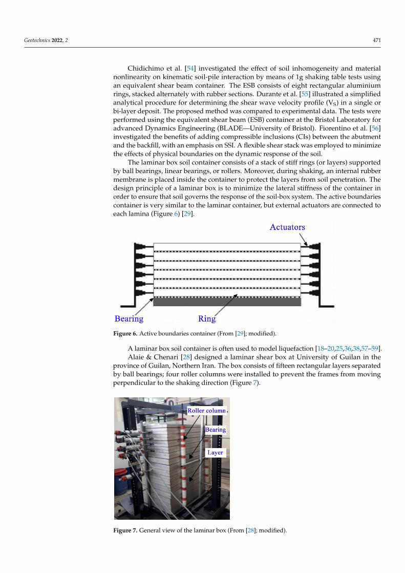
Ecemis [25] carried out 1D shaking table tests in order to simulate the liquefaction of loose to medium dense saturated sands. The laminar box was composed of 24 rings made of aluminium I-beams. In order to reduce the friction between the layer, rings were sep-arated and supported by eight rollers (Figure 8).
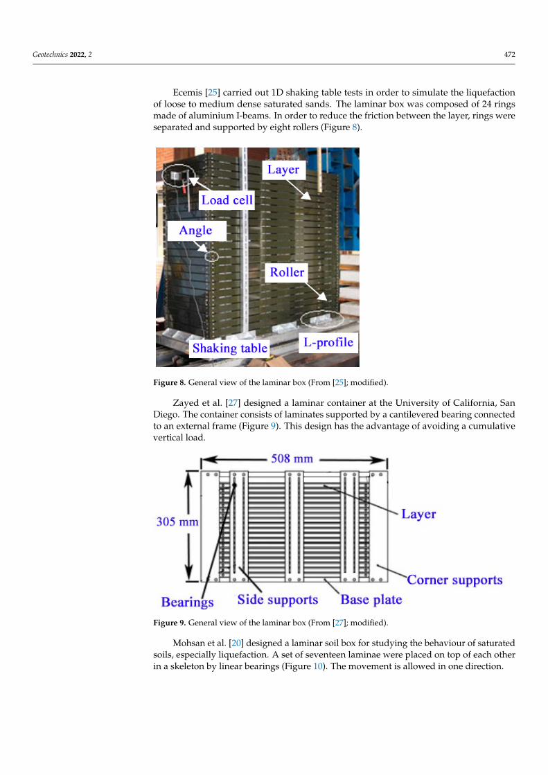
Zayed et al. [27] designed a laminar container at the University of California, San Diego. The container consists of laminates supported by a cantilevered bearing connected to an external frame (Figure 9). This design has the advantage of avoiding a cumulative vertical load.
Mohsan et al. [20] designed a laminar soil box for studying the behaviour of satu-rated soils, especially liquefaction. A set of seventeen laminae were placed on top of each other in a skeleton by linear bearings (Figure 10). The movement is allowed in one direc-tion.
Thevanayagam et al. [57] studied the effects of liquefaction and lateral spreading using a 2D laminar box system. The laminar box consists of 24 octagon-shaped alumin-ium laminates made of I-beams. The rings were separated by high-capacity ball bearings
Figure 6. Active boundaries container (From [29]; modified).
A laminar box soil container is often used to model liquefaction [18–20,25,36,38,57–59].Alaie & Chenari [28] designed a laminar shear box at University of Guilan in the
province of Guilan, Northern Iran. The box consists of fifteen rectangular layers separatedby ball bearings; four roller columns were installed to prevent the frames from movingperpendicular to the shaking direction (Figure 7).
Geotechnics 2022, 2, FOR PEER REVIEW 6
placed between the laminates. Figure 11 shows the laminar box system. Zeghal et al. [36] performed a number of centrifuge model tests using a 2D laminar container. This consists of twelve-sided rings separated from the ones above and below by roller bearings. A view of the laminar container is reported in Figure 12.
Figure 7. General view of the laminar box (From [28]; modified).
Figure 8. General view of the laminar box (From [25]; modified).
Figure 9. General view of the laminar box (From [27]; modified).
Figure 7. General view of the laminar box (From [28]; modified).
Geotechnics 2022, 2 472
Ecemis [25] carried out 1D shaking table tests in order to simulate the liquefactionof loose to medium dense saturated sands. The laminar box was composed of 24 ringsmade of aluminium I-beams. In order to reduce the friction between the layer, rings wereseparated and supported by eight rollers (Figure 8).
Geotechnics 2022, 2, FOR PEER REVIEW 6
placed between the laminates. Figure 11 shows the laminar box system. Zeghal et al. [36] performed a number of centrifuge model tests using a 2D laminar container. This consists of twelve-sided rings separated from the ones above and below by roller bearings. A view of the laminar container is reported in Figure 12.
Figure 7. General view of the laminar box (From [28]; modified).
Figure 8. General view of the laminar box (From [25]; modified).
Figure 9. General view of the laminar box (From [27]; modified).
Figure 8. General view of the laminar box (From [25]; modified).
Zayed et al. [27] designed a laminar container at the University of California, SanDiego. The container consists of laminates supported by a cantilevered bearing connectedto an external frame (Figure 9). This design has the advantage of avoiding a cumulativevertical load.
Geotechnics 2022, 2, FOR PEER REVIEW 6
placed between the laminates. Figure 11 shows the laminar box system. Zeghal et al. [36] performed a number of centrifuge model tests using a 2D laminar container. This consists of twelve-sided rings separated from the ones above and below by roller bearings. A view of the laminar container is reported in Figure 12.
Figure 7. General view of the laminar box (From [28]; modified).
Figure 8. General view of the laminar box (From [25]; modified).
Figure 9. General view of the laminar box (From [27]; modified). Figure 9. General view of the laminar box (From [27]; modified).
Mohsan et al. [20] designed a laminar soil box for studying the behaviour of saturatedsoils, especially liquefaction. A set of seventeen laminae were placed on top of each otherin a skeleton by linear bearings (Figure 10). The movement is allowed in one direction.

Geotechnics 2022, 2 473Geotechnics 2022, 2, FOR PEER REVIEW 7
(a) (b)
Figure 10. (a) Laminae (b) skeleton for laminae (From [20]; modified).
Figure 11. Laminar box system (From Thevanayagam et al. [57]; modified).
Figure 12. General view of the laminar container (From [36]; modified).
Jafarzadeh [30] designed a 2D laminar box for the shaking table of the Earthquake Research Centre of Sharif University of Technology (SUT). The system was composed of 24 layers separated by transfer ball bearings. In the four sides of the box, four steel col-umns were installed to prevent oversize deformations (Figure 13).
Figure 10. (a) Laminae (b) skeleton for laminae (From [20]; modified).
Thevanayagam et al. [57] studied the effects of liquefaction and lateral spreadingusing a 2D laminar box system. The laminar box consists of 24 octagon-shaped aluminiumlaminates made of I-beams. The rings were separated by high-capacity ball bearingsplaced between the laminates. Figure 11 shows the laminar box system. Zeghal et al. [36]performed a number of centrifuge model tests using a 2D laminar container. This consistsof twelve-sided rings separated from the ones above and below by roller bearings. A viewof the laminar container is reported in Figure 12.
Geotechnics 2022, 2, FOR PEER REVIEW 7
(a) (b)
Figure 10. (a) Laminae (b) skeleton for laminae (From [20]; modified).
Figure 11. Laminar box system (From Thevanayagam et al. [57]; modified).
Figure 12. General view of the laminar container (From [36]; modified).
Jafarzadeh [30] designed a 2D laminar box for the shaking table of the Earthquake Research Centre of Sharif University of Technology (SUT). The system was composed of 24 layers separated by transfer ball bearings. In the four sides of the box, four steel col-umns were installed to prevent oversize deformations (Figure 13).
Figure 11. Laminar box system (From Thevanayagam et al. [57]; modified).
Geotechnics 2022, 2, FOR PEER REVIEW 7
(a) (b)
Figure 10. (a) Laminae (b) skeleton for laminae (From [20]; modified).
Figure 11. Laminar box system (From Thevanayagam et al. [57]; modified).
Figure 12. General view of the laminar container (From [36]; modified).
Jafarzadeh [30] designed a 2D laminar box for the shaking table of the Earthquake Research Centre of Sharif University of Technology (SUT). The system was composed of 24 layers separated by transfer ball bearings. In the four sides of the box, four steel col-umns were installed to prevent oversize deformations (Figure 13).
Figure 12. General view of the laminar container (From [36]; modified).

Geotechnics 2022, 2 474
Jafarzadeh [30] designed a 2D laminar box for the shaking table of the EarthquakeResearch Centre of Sharif University of Technology (SUT). The system was composed of24 layers separated by transfer ball bearings. In the four sides of the box, four steel columnswere installed to prevent oversize deformations (Figure 13).
Geotechnics 2022, 2, FOR PEER REVIEW 8
Figure 13. General view of the laminar container (From Jafarzadeh [30]; modified).
A 2D laminar shear box was designed by Ueng et al. [38] at the National Centre for Research on Earthquake Engineering (NCREE) in Taiwan for the study of liquefaction and soil-structure interaction. To allow biaxial motion and to ensure non-torsional mo-tion, a special mechanism design was adopted.
The laminar box is composed of 15 layers supported on the surrounding rigid steel walls. Each layer consists of two nested frames, an inner frame with inside dimensions of 1880 mm by 1880 mm and an outer frame with inside dimensions of 1940 mm by 2340 mm.
Schematic drawings of the biaxial laminar box are reported in Figure 14, while in Table 1 several examples of laminar shear boxes have been summarized.
(a) (b)
Figure 14. Schematic drawings of the biaxial laminar box (From [60]; modified): (a) top view and (b) side view.
Table 1. Examples of laminar shear boxes.
Reference 1g/n-g Direction Design Alaie & Chenari [28] 1g 1D Layers supported by ball bearings
Ecemis [25] 1g 1D Layers supported by rollers Zayed et al. [27] n-g 1D Layers supported by bearings connected to an external frame
Mohsan et al. [20] n-g 1D Layers placed in a skeleton supported by linear bearing Thevanayagam et al. [57] n-g 2D Layers supported by ball bearings
Zeghal et al. [36] n-g 2D Layers supported by roller bearings Jafarzadeh [30] 1g 2D Layers supported by ball bearings Ueng et al. [38] 1g 2D Layers of frames supported on the surrounding rigid steel walls
Figure 13. General view of the laminar container (From Jafarzadeh [30]; modified).
A 2D laminar shear box was designed by Ueng et al. [38] at the National Centre forResearch on Earthquake Engineering (NCREE) in Taiwan for the study of liquefaction andsoil-structure interaction. To allow biaxial motion and to ensure non-torsional motion, aspecial mechanism design was adopted.
The laminar box is composed of 15 layers supported on the surrounding rigid steelwalls. Each layer consists of two nested frames, an inner frame with inside dimensions of1880 mm by 1880 mm and an outer frame with inside dimensions of 1940 mm by 2340 mm.
Schematic drawings of the biaxial laminar box are reported in Figure 14, while inTable 1 several examples of laminar shear boxes have been summarized.
Geotechnics 2022, 2, FOR PEER REVIEW 8
Figure 13. General view of the laminar container (From Jafarzadeh [30]; modified).
A 2D laminar shear box was designed by Ueng et al. [38] at the National Centre for Research on Earthquake Engineering (NCREE) in Taiwan for the study of liquefaction and soil-structure interaction. To allow biaxial motion and to ensure non-torsional mo-tion, a special mechanism design was adopted.
The laminar box is composed of 15 layers supported on the surrounding rigid steel walls. Each layer consists of two nested frames, an inner frame with inside dimensions of 1880 mm by 1880 mm and an outer frame with inside dimensions of 1940 mm by 2340 mm.
Schematic drawings of the biaxial laminar box are reported in Figure 14, while in Table 1 several examples of laminar shear boxes have been summarized.
(a) (b)
Figure 14. Schematic drawings of the biaxial laminar box (From [60]; modified): (a) top view and (b) side view.
Table 1. Examples of laminar shear boxes.
Reference 1g/n-g Direction Design Alaie & Chenari [28] 1g 1D Layers supported by ball bearings
Ecemis [25] 1g 1D Layers supported by rollers Zayed et al. [27] n-g 1D Layers supported by bearings connected to an external frame
Mohsan et al. [20] n-g 1D Layers placed in a skeleton supported by linear bearing Thevanayagam et al. [57] n-g 2D Layers supported by ball bearings
Zeghal et al. [36] n-g 2D Layers supported by roller bearings Jafarzadeh [30] 1g 2D Layers supported by ball bearings Ueng et al. [38] 1g 2D Layers of frames supported on the surrounding rigid steel walls
Figure 14. Schematic drawings of the biaxial laminar box (From [60]; modified): (a) top view and(b) side view.
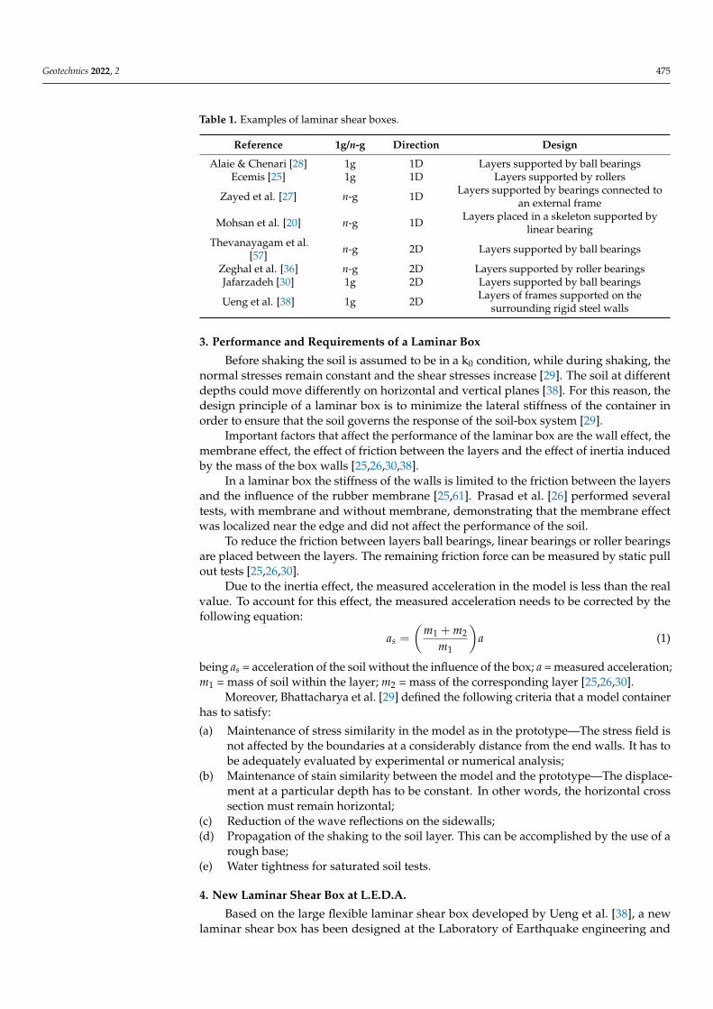
Geotechnics 2022, 2 475
Table 1. Examples of laminar shear boxes.
Reference 1g/n-g Direction Design
Alaie & Chenari [28] 1g 1D Layers supported by ball bearingsEcemis [25] 1g 1D Layers supported by rollers
Zayed et al. [27] n-g 1D Layers supported by bearings connected toan external frame
Mohsan et al. [20] n-g 1D Layers placed in a skeleton supported bylinear bearing
Thevanayagam et al.[57] n-g 2D Layers supported by ball bearings
Zeghal et al. [36] n-g 2D Layers supported by roller bearingsJafarzadeh [30] 1g 2D Layers supported by ball bearings
Ueng et al. [38] 1g 2D Layers of frames supported on thesurrounding rigid steel walls
3. Performance and Requirements of a Laminar Box
Before shaking the soil is assumed to be in a k0 condition, while during shaking, thenormal stresses remain constant and the shear stresses increase [29]. The soil at differentdepths could move differently on horizontal and vertical planes [38]. For this reason, thedesign principle of a laminar box is to minimize the lateral stiffness of the container inorder to ensure that the soil governs the response of the soil-box system [29].
Important factors that affect the performance of the laminar box are the wall effect, themembrane effect, the effect of friction between the layers and the effect of inertia inducedby the mass of the box walls [25,26,30,38].
In a laminar box the stiffness of the walls is limited to the friction between the layersand the influence of the rubber membrane [25,61]. Prasad et al. [26] performed severaltests, with membrane and without membrane, demonstrating that the membrane effectwas localized near the edge and did not affect the performance of the soil.
To reduce the friction between layers ball bearings, linear bearings or roller bearingsare placed between the layers. The remaining friction force can be measured by static pullout tests [25,26,30].
Due to the inertia effect, the measured acceleration in the model is less than the realvalue. To account for this effect, the measured acceleration needs to be corrected by thefollowing equation:
as =
(m1 + m2
m1
)a (1)
being as = acceleration of the soil without the influence of the box; a = measured acceleration;m1 = mass of soil within the layer; m2 = mass of the corresponding layer [25,26,30].
Moreover, Bhattacharya et al. [29] defined the following criteria that a model containerhas to satisfy:
(a) Maintenance of stress similarity in the model as in the prototype—The stress field isnot affected by the boundaries at a considerably distance from the end walls. It has tobe adequately evaluated by experimental or numerical analysis;
(b) Maintenance of stain similarity between the model and the prototype—The displace-ment at a particular depth has to be constant. In other words, the horizontal crosssection must remain horizontal;
(c) Reduction of the wave reflections on the sidewalls;(d) Propagation of the shaking to the soil layer. This can be accomplished by the use of a
rough base;(e) Water tightness for saturated soil tests.
4. New Laminar Shear Box at L.E.D.A.
Based on the large flexible laminar shear box developed by Ueng et al. [38], a newlaminar shear box has been designed at the Laboratory of Earthquake engineering and
Geotechnics 2022, 2 476
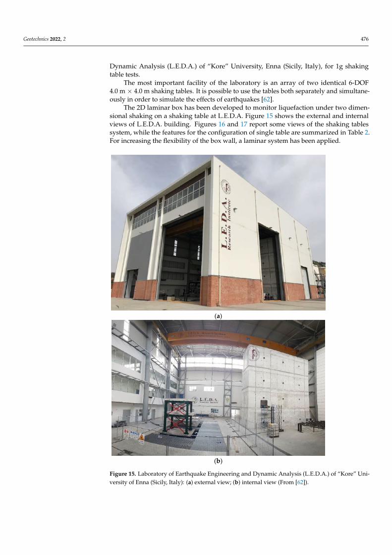
Dynamic Analysis (L.E.D.A.) of “Kore” University, Enna (Sicily, Italy), for 1g shakingtable tests.
The most important facility of the laboratory is an array of two identical 6-DOF4.0 m × 4.0 m shaking tables. It is possible to use the tables both separately and simultane-ously in order to simulate the effects of earthquakes [62].
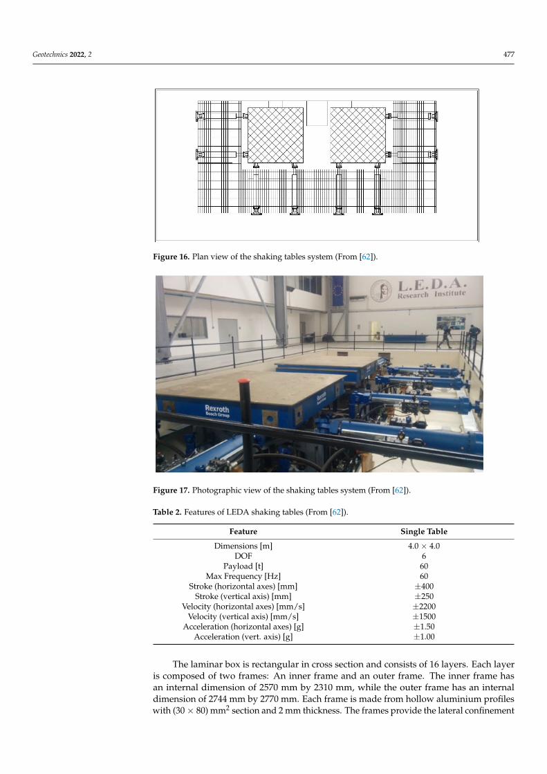
The 2D laminar box has been developed to monitor liquefaction under two dimen-sional shaking on a shaking table at L.E.D.A. Figure 15 shows the external and internalviews of L.E.D.A. building. Figures 16 and 17 report some views of the shaking tablessystem, while the features for the configuration of single table are summarized in Table 2.For increasing the flexibility of the box wall, a laminar system has been applied.
Geotechnics 2022, 2, FOR PEER REVIEW 10
sion of 2744 mm by 2770 mm. Each frame is made from hollow aluminium profiles with (30 × 80) mm2 section and 2 mm thickness. The frames provide the lateral confinement of the soil in order to reproduce the k0 conditions. Indeed, aluminium is chosen for its strength to provide unyielding boundaries and for its light to reduce the inertial effect of the frame on the soil during shaking [63]. The inertia effect induced by the mass of the layers can lead to damping. Due to the inertia effect, the measured acceleration in the model is less than the real value. Considering the box filled of saturated sand, the cor-rection factor (Equation (1)) is equal to 0.998. The isometric view of the inner and outer frames is shown in Figure 18.
(a)
(b)
Figure 15. Laboratory of Earthquake Engineering and Dynamic Analysis (L.E.D.A.) of “Kore” University of Enna (Sicily, Italy): (a) external view; (b) internal view (From [62]). Figure 15. Laboratory of Earthquake Engineering and Dynamic Analysis (L.E.D.A.) of “Kore” Uni-versity of Enna (Sicily, Italy): (a) external view; (b) internal view (From [62]).
Geotechnics 2022, 2 477Geotechnics 2022, 2, FOR PEER REVIEW 11
Figure 16. Plan view of the shaking tables system (From [62]).
Figure 17. Photographic view of the shaking tables system (From [62]).
Table 2. Features of LEDA shaking tables (From [62]).
Feature Single Table Dimensions [m] 4.0 × 4.0
DOF 6 Payload [t] 60
Max Frequency [Hz] 60 Stroke (horizontal axes) [mm] ±400
Stroke (vertical axis) [mm] ±250 Velocity (horizontal axes) [mm/s] ±2200
Velocity (vertical axis) [mm/s] ±1500 Acceleration (horizontal axes) [g] ±1.50
Acceleration (vert. axis) [g] ±1.00
Figure 16. Plan view of the shaking tables system (From [62]).
Geotechnics 2022, 2, FOR PEER REVIEW 11
Figure 16. Plan view of the shaking tables system (From [62]).
Figure 17. Photographic view of the shaking tables system (From [62]).
Table 2. Features of LEDA shaking tables (From [62]).
Feature Single Table Dimensions [m] 4.0 × 4.0
DOF 6 Payload [t] 60
Max Frequency [Hz] 60 Stroke (horizontal axes) [mm] ±400
Stroke (vertical axis) [mm] ±250 Velocity (horizontal axes) [mm/s] ±2200
Velocity (vertical axis) [mm/s] ±1500 Acceleration (horizontal axes) [g] ±1.50
Acceleration (vert. axis) [g] ±1.00
Figure 17. Photographic view of the shaking tables system (From [62]).
Table 2. Features of LEDA shaking tables (From [62]).
Feature Single Table
Dimensions [m] 4.0 × 4.0DOF 6
Payload [t] 60Max Frequency [Hz] 60
Stroke (horizontal axes) [mm] ±400Stroke (vertical axis) [mm] ±250
Velocity (horizontal axes) [mm/s] ±2200Velocity (vertical axis) [mm/s] ±1500
Acceleration (horizontal axes) [g] ±1.50Acceleration (vert. axis) [g] ±1.00
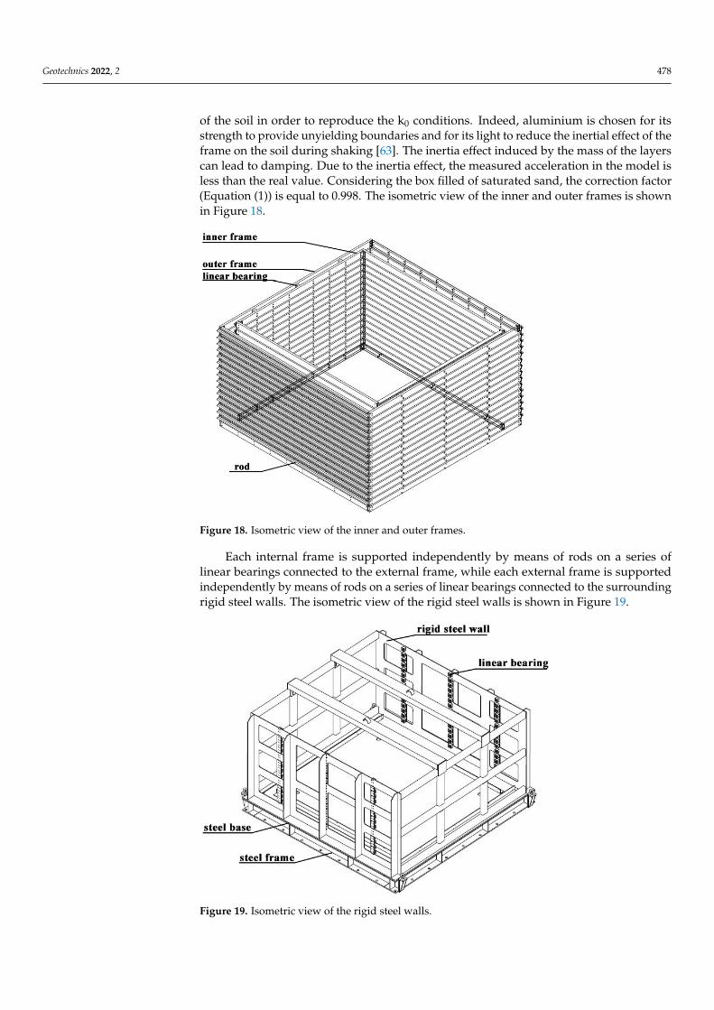
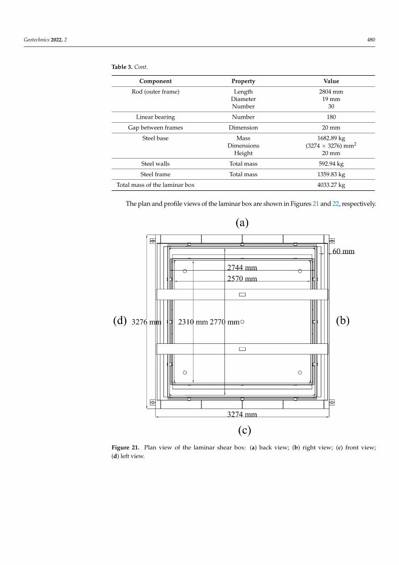
The laminar box is rectangular in cross section and consists of 16 layers. Each layeris composed of two frames: An inner frame and an outer frame. The inner frame hasan internal dimension of 2570 mm by 2310 mm, while the outer frame has an internaldimension of 2744 mm by 2770 mm. Each frame is made from hollow aluminium profileswith (30 × 80) mm2 section and 2 mm thickness. The frames provide the lateral confinement
Geotechnics 2022, 2 478
of the soil in order to reproduce the k0 conditions. Indeed, aluminium is chosen for itsstrength to provide unyielding boundaries and for its light to reduce the inertial effect of theframe on the soil during shaking [63]. The inertia effect induced by the mass of the layerscan lead to damping. Due to the inertia effect, the measured acceleration in the model isless than the real value. Considering the box filled of saturated sand, the correction factor(Equation (1)) is equal to 0.998. The isometric view of the inner and outer frames is shownin Figure 18.
Geotechnics 2022, 2, FOR PEER REVIEW 12
Figure 18. Isometric view of the inner and outer frames.
Each internal frame is supported independently by means of rods on a series of linear bearings connected to the external frame, while each external frame is supported independently by means of rods on a series of linear bearings connected to the sur-rounding rigid steel walls. The isometric view of the rigid steel walls is shown in Figure 19.
Figure 19. Isometric view of the rigid steel walls.
Figure 18. Isometric view of the inner and outer frames.
Each internal frame is supported independently by means of rods on a series oflinear bearings connected to the external frame, while each external frame is supportedindependently by means of rods on a series of linear bearings connected to the surroundingrigid steel walls. The isometric view of the rigid steel walls is shown in Figure 19.
Geotechnics 2022, 2, FOR PEER REVIEW 12
Figure 18. Isometric view of the inner and outer frames.
Each internal frame is supported independently by means of rods on a series of linear bearings connected to the external frame, while each external frame is supported independently by means of rods on a series of linear bearings connected to the sur-rounding rigid steel walls. The isometric view of the rigid steel walls is shown in Figure 19.
Figure 19. Isometric view of the rigid steel walls.
Figure 19. Isometric view of the rigid steel walls.

Geotechnics 2022, 2 479
Linear bearings allow a maximum displacement of ±150 mm in the two horizontaldirections with almost negligible friction. Thanks to this arrangement, the external framescan move in the x direction and, at the same time, the internal frames can move in the ydirection. This design has several advantages: the weight of each frame is transferred to thesurrounding rigid steel walls; the effects of inertia and friction do not accumulate along thedepth; each frame can move independently without torsion; the horizontal cross sectionremains horizontal (strain similarity).
Between the layers, there is a 20 mm gap making the total height 1600 mm. The lowestlayer is fixed on a steel base of dimensions 3274 mm × 3276 mm × 20 mm. To reinforce thebase, a steel frame is installed between the base and the shaking table. A drainage systemis added on a steel base. It consists of water tubes and four valves. The plan view of thesteel frame is shown in Figure 20.
Geotechnics 2022, 2, FOR PEER REVIEW 13
Linear bearings allow a maximum displacement of ±150 mm in the two horizontal directions with almost negligible friction. Thanks to this arrangement, the external frames can move in the x direction and, at the same time, the internal frames can move in the y direction. This design has several advantages: the weight of each frame is trans-ferred to the surrounding rigid steel walls; the effects of inertia and friction do not ac-cumulate along the depth; each frame can move independently without torsion; the horizontal cross section remains horizontal (strain similarity).
Between the layers, there is a 20 mm gap making the total height 1600 mm. The lowest layer is fixed on a steel base of dimensions 3274 mm × 3276 mm × 20 mm. To re-inforce the base, a steel frame is installed between the base and the shaking table. A drainage system is added on a steel base. It consists of water tubes and four valves. The plan view of the steel frame is shown in Figure 20.
Figure 20. Plan view of the steel frame.
During shaking, to improve the shear stress transition from the steel base to the soil, a thin layer of gravels is placed on the base. Moreover, a 2 mm thick rubber membrane with high elasticity is installed inside the box to provide water tightness and protect the external mechanism from soil penetration. The main components of the laminar shear box are reported in Table 3.
Table 3. Components of the laminar shear box.
Component Property Value Inner frame Mass 12.07 kg
Internal Dimensions (2570 × 2310) mm2 Number 16 Height 80 mm
Outer frame Mass 12.53 kg Internal Dimensions (2744 × 2770) mm2 Number 16 Height 80 mm
Rod (inner frame) Length 2370 mm
Figure 20. Plan view of the steel frame.
During shaking, to improve the shear stress transition from the steel base to the soil,a thin layer of gravels is placed on the base. Moreover, a 2 mm thick rubber membranewith high elasticity is installed inside the box to provide water tightness and protect theexternal mechanism from soil penetration. The main components of the laminar shear boxare reported in Table 3.
Table 3. Components of the laminar shear box.
Component Property Value
Inner frame Mass 12.07 kgInternal Dimensions (2570 × 2310) mm2
Number 16Height 80 mm
Outer frame Mass 12.53 kgInternal Dimensions (2744 × 2770) mm2
Number 16Height 80 mm
Rod (inner frame) Length 2370 mmDiameter 19 mmNumber 30
Geotechnics 2022, 2 480
Table 3. Cont.
Component Property Value
Rod (outer frame) Length 2804 mmDiameter 19 mmNumber 30
Linear bearing Number 180
Gap between frames Dimension 20 mm
Steel base Mass 1682.89 kgDimensions (3274 × 3276) mm2
Height 20 mm
Steel walls Total mass 592.94 kg
Steel frame Total mass 1359.83 kg
Total mass of the laminar box 4033.27 kg
The plan and profile views of the laminar box are shown in Figures 21 and 22, respectively.
Geotechnics 2022, 2, FOR PEER REVIEW 14
Diameter 19 mm Number 30
Rod (outer frame) Length 2804 mm Diameter 19 mm Number 30
Linear bearing Number 180 Gap between frames Dimension 20 mm
Steel base Mass 1682.89 kg Dimensions (3274 × 3276) mm2 Height 20 mm
Steel walls Total mass 592.94 kg Steel frame Total mass 1359.83 kg
Total mass of the laminar box 4033.27 kg
The plan and profile views of the laminar box are shown in Figures 21 and 22, re-spectively.
Figure 21. Plan view of the laminar shear box: (a) back view; (b) right view; (c) front view; (d) left view. Figure 21. Plan view of the laminar shear box: (a) back view; (b) right view; (c) front view;(d) left view.

Geotechnics 2022, 2 481Geotechnics 2022, 2, FOR PEER REVIEW 15
(a)
(b)
(c)
Figure 22. Cont.

Geotechnics 2022, 2 482Geotechnics 2022, 2, FOR PEER REVIEW 16
(d)
Figure 22. Profile views of the laminar shear box: (a) back view; (b) right view; (c) front view; (d) left view.
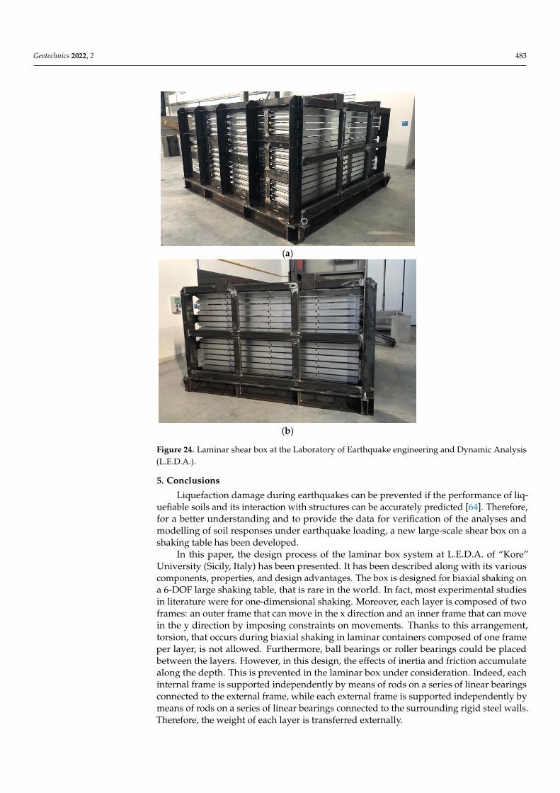
The isometric and 3D views are illustrated in Figure 23. The built laminar shear box is shown in Figure 24.
Figure 22. Profile views of the laminar shear box: (a) back view; (b) right view; (c) front view;(d) left view.
The isometric and 3D views are illustrated in Figure 23. The built laminar shear box isshown in Figure 24.
Geotechnics 2022, 2, FOR PEER REVIEW 17
(a)
(b)
Figure 23. (a) The isometric and (b) 3D views of the laminar shear box. Figure 23. (a) The isometric and (b) 3D views of the laminar shear box.
Geotechnics 2022, 2 483Geotechnics 2022, 2, FOR PEER REVIEW 18
(a)
(b)
Figure 24. Laminar shear box at the Laboratory of Earthquake engineering and Dynamic Analysis (L.E.D.A.).
5. Conclusions Liquefaction damage during earthquakes can be prevented if the performance of
liquefiable soils and its interaction with structures can be accurately predicted [64]. Therefore, for a better understanding and to provide the data for verification of the analyses and modelling of soil responses under earthquake loading, a new large-scale shear box on a shaking table has been developed.
In this paper, the design process of the laminar box system at L.E.D.A. of “Kore” University (Sicily, Italy) has been presented. It has been described along with its various components, properties, and design advantages. The box is designed for biaxial shaking on a 6-DOF large shaking table, that is rare in the world. In fact, most experimental studies in literature were for one-dimensional shaking. Moreover, each layer is composed of two frames: an outer frame that can move in the x direction and an inner frame that can move in the y direction by imposing constraints on movements. Thanks to this ar-rangement, torsion, that occurs during biaxial shaking in laminar containers composed of one frame per layer, is not allowed. Furthermore, ball bearings or roller bearings could be placed between the layers. However, in this design, the effects of inertia and friction ac-cumulate along the depth. This is prevented in the laminar box under consideration. In-deed, each internal frame is supported independently by means of rods on a series of linear bearings connected to the external frame, while each external frame is supported independently by means of rods on a series of linear bearings connected to the sur-rounding rigid steel walls. Therefore, the weight of each layer is transferred externally.
Figure 24. Laminar shear box at the Laboratory of Earthquake engineering and Dynamic Analysis(L.E.D.A.).
5. Conclusions
Liquefaction damage during earthquakes can be prevented if the performance of liq-uefiable soils and its interaction with structures can be accurately predicted [64]. Therefore,for a better understanding and to provide the data for verification of the analyses andmodelling of soil responses under earthquake loading, a new large-scale shear box on ashaking table has been developed.
In this paper, the design process of the laminar box system at L.E.D.A. of “Kore”University (Sicily, Italy) has been presented. It has been described along with its variouscomponents, properties, and design advantages. The box is designed for biaxial shaking ona 6-DOF large shaking table, that is rare in the world. In fact, most experimental studiesin literature were for one-dimensional shaking. Moreover, each layer is composed of twoframes: an outer frame that can move in the x direction and an inner frame that can movein the y direction by imposing constraints on movements. Thanks to this arrangement,torsion, that occurs during biaxial shaking in laminar containers composed of one frameper layer, is not allowed. Furthermore, ball bearings or roller bearings could be placedbetween the layers. However, in this design, the effects of inertia and friction accumulatealong the depth. This is prevented in the laminar box under consideration. Indeed, eachinternal frame is supported independently by means of rods on a series of linear bearingsconnected to the external frame, while each external frame is supported independently bymeans of rods on a series of linear bearings connected to the surrounding rigid steel walls.Therefore, the weight of each layer is transferred externally.

Geotechnics 2022, 2 484
The new laminar shear box will be placed on a 4.0 m × 4.0 m shaking table in order tostudy the dynamic soil-structure interaction (DSSI) on liquefiable soils. Seismic-inducedsoil liquefaction is a major cause of damage and loss of human lives during earthquakes.Thus, the evaluation of the susceptibility of a site to liquefaction and the assessment ofits effect on structures are important topics in seismic geotechnical engineering. Severalstudies have been carried out in the last decades to assess soil liquefaction. However, it isstill a challenging task. The main issues are the uncertainties associated to soil behaviourand the large number of variables related to the interaction between soil and water.
The numerical simulations and the use of constitutive models are a valuable help inthese complex problems. However, liquefaction is difficult to achieve in the constitutivemodels and requires a large number of input parameters. Instead, shaking table tests arefavourable thanks to the ability to provide realistic and economic results in terms of excesspore-pressure generation.
The new laminar box has been designed and assembled at L.E.D.A. The next researchsteps consist in conducting experimental studies by the laminar shear box and to analysethe gap areas of the numerical modelling to be incorporated in the future simulations toexactly capture the liquefaction phenomenon. Shaking table tests will be carried out onsaturated sandy soil in the new laminar box. Then, the measured data inside the soil willbe compared with those obtained by means of numerical analysis in order to validateadvanced numerical models.
Author Contributions: Data curation, F.C.; Funding acquisition, F.C.; Investigation, V.L.; Method-ology, S.G. and M.S.V.S.; Supervision, V.L.; Writing—original draft, S.G. and M.S.V.S.; Writing—review & editing, S.G. and M.S.V.S. All authors have read and agreed to the published version ofthe manuscript.
Funding: This research work was funded by the MIUR (Ministry of Education, Universities andResearch [Italy]) through the project entitled “eWAS: an early WArning System for cultural-heritage”(Project code: ARS01_00926/CUP J66C18000390005).
Acknowledgments: The authors acknowledge the financial support received from the MIUR (Min-istry of Education, Universities and Research [Italy]) through the project entitled “eWAS: an earlyWArning System for cultural-heritage” (Project code: ARS01_00926/CUP J66C18000390005), financedwith the PNR 2015-2020 (National Research Program). The authors authorize the MIUR to reproduceand distribute reprints for Governmental purposes, notwithstanding any copyright notations thereon.Any opinions, findings, and conclusions or recommendations expressed in this material are those ofthe authors and do not necessarily reflect the views of the MIUR.
Conflicts of Interest: The authors declare no conflict of interest.
References1. Galavi, V.; Petalas, A.; Brinkgreve, R.B.J. Finite element modelling of seismic liquefaction in soils. Geotech. Eng. J. SEAGS AGSSEA
2013, 44, 55–64.2. Sadrekarimi, A.; Ghalandarzadeh, A. Evaluation of gravel drains and compacted sand piles in mitigating liquefaction. Proc. Inst.
Civ. Eng.-Ground Improv. 2005, 9, 91–104. [CrossRef]3. Lentini, V.; Castelli, F. Liquefaction resistance of sandy soils from undrained cyclic triaxial tests. Geotech. Geol. Eng. 2018, 37,
201–216. [CrossRef]4. Castelli, F.; Cavallaro, A.; Grasso, S.; Lentini, V. Undrained Cyclic Laboratory Behavior of Sandy Soils. Geosciences 2019, 9, 512.
[CrossRef]5. Ciancimino, A.; Lanzo, G.; Alleanza, G.A.; Amoroso, S.; Bardotti, R.; Biondi, G.; Cascone, E.; Castelli, F.; Di Giulio, A.; D’onofrio,
A.; et al. Dynamic characterization of fine-grained soils in Central Italy by laboratory testing. Bull. Earthq. Eng. 2020, 18,5503–5531. [CrossRef]
6. Boulanger, R.W.; Idriss, I.M. CPT and SPT Based Liquefaction Triggering Procedures; Report, No. UCD/CGM-14/01; Center forGeotechnical Modeling, Department of Civil and Environmental Engineering, College of Engineering, University of California:Davis, CA, USA, 2014.
7. Boulanger, R.W.; Idriss, I.M. CPT-based liquefaction triggering procedure. J. Geotech. Geoenvir. Eng. 2015, 142, 2. [CrossRef]8. Castelli, F.; Cavallaro, A.; Grasso, S. SDMT soil testing for the local site response analysis. In Proceedings of the 1st IMEKO TC4
International Workshop on Metrology for Geotechnics, Benevento, Italy, 17–18 March 2016; pp. 143–148, ISBN 978-92-990075-0-1.

Geotechnics 2022, 2 485
9. Castelli, F.; Lentini, V.; Trifarò, C.A. 1D seismic analysis of earth dams: The example of the Lentini site. Procedia Eng. 2016, 158,356–361. [CrossRef]
10. Grasso, S.; Maugeri, M. The Seismic Dilatometer Marchetti Test (SDMT) for Evaluating Liquefaction Potential under CyclicLoading. In Proceedings of the IV Geotechnical Earthquake Engineering and Soil Dynamic, Sacramento, CA, USA, 18–22 May2008; ISBN 978-0-7844-0975-6. [CrossRef]
11. Grasso, S.; Massimino, M.; Sammito, M. New Stress Reduction Factor for Evaluating Soil Liquefaction in the Coastal Area ofCatania (Italy). Geosciences 2020, 11, 12. [CrossRef]
12. Maugeri, M.; Grasso, S. Liquefaction potential evaluation at Catania Harbour (Italy). WIT Trans. Built Environ. 2013, 132, 69–81.[CrossRef]
13. Bhatnagar, S.; Kumari, S.; Sawant, V.A. Numerical Analysis of Earth Embankment Resting on Liquefiable Soil and RemedialMeasures. Int. J. Géoméch. 2016, 16, 04015029. [CrossRef]
14. Castelli, F.; Grasso, S.; Lentini, V.; Sammito, M. Effects of Soil-Foundation-Interaction on the Seismic Response of a Cooling Towerby 3D-FEM Analysis. Geosciences 2021, 11, 200. [CrossRef]
15. Makra, A. Evaluation of the UBC3D-PLM Constitutive Model for Prediction of Earthquake Induced Liquefaction on EmbankmentDams. Master’s Thesis, Delft University of Technology, Delft, The Netherlands, 2013.
16. Ishihara, K.; Yamazaki, F. Cyclic Simple Shear Tests on Saturated Sand in Multi-Directional Loading. Soils Found. 1980, 20, 45–59.[CrossRef]
17. Cavallaro, A.; Capilleri, P.P.; Grasso, S. Site characterization by dynamic in situ and laboratory tests for liquefaction potentialevaluation during emilia romagna earthquake. Geosciences 2018, 8, 242. [CrossRef]
18. Bojadjieva, J.; Sesov, V.; Edip, K.; Gjorgiev, I. Some important aspects in experimental setup for liquefaction studies on shak-ing table tests. In Proceedings of the 2nd European Conference Earthquake Engineering and Seismology, Istanbul, Turkey,25–29 August 2014.
19. Chen, C.H.; Ueng, T.S. Dynamic responses of model pile in saturated sand in shaking table tests. In Proceedings of the 5thInternational Conference on Earthquake Geotechnical Engineering, Santiago, Chile, 9–14 January 2011.
20. Mohsan, M.; Kiyota, T.; Munoz, H.; Nihaaj, M.; Katagiri, T. Fabrication and performance of laminar soil box with rigid soil box forliquefaction study. In Bulletin of Earthquake Resistant Structure Research Center 2018; Institute of Industrial Science (IIS), Universityof Tokyo: Tokyo, Japan, 2018; Volume 51.
21. Ashford, S.; Rollins, K.; Lane, J. Blast-induced liquefaction for full-scale foundation testing. J. Geotech. Geoen-Vironmental Eng.2004, 130, 798–806. [CrossRef]
22. Castelli, F.; Grasso, S.; Lentini, V.; Massimino, M.R. In situ measurements for evaluating liquefaction potential under cyclicloading. In Proceedings of the 1st IMEKO TC-4 Int. Workshop on Metrology for Geotechnics, Benevento, Italy, 17–18 March 2016;pp. 79–84, ISBN 978-92-990075-0-1.
23. Castelli, F.; Cavallaro, A.; Ferraro, A.; Grasso, S.; Lentini, V.; Massimino, M.R. Static and dynamic properties of soils in catania(Italy). Ann. Geophys. 2018, 61, 221. [CrossRef]
24. Turan, A.; Hinchberger, S.D.; El Naggar, M.H. Seismic soil–structure interaction in buildings on stiff clay with embedded basementstories. Can. Geotech. J. 2013, 50, 858–873. [CrossRef]
25. Ecemis, N. Simulation of seismic liquefaction: 1-g model testing system and shaking table tests. Eur. J. Environ. Civ. Eng. 2013, 17,899–919. [CrossRef]
26. Prasad, S.K.; Towhata, I.; Chandradhara, G.P.; Nanjunaswamy, P. Shaking table tests in earthquake geotechnical engineering.Curr. Sci. 2004, 87, 1398–1404.
27. Zayed, M.; Luo, L.; Kim, K.; McCarteney, J.S.; Elgamal, A. Development and performance of a laminar container for seismic cen-trifuge modeling. In Proceedings of the 3rd International Conference on Performance-Based Design in Earthquake GeotechnicalEngineering, Vancouver, BC, Canada, 16–19 July 2017.
28. Alaie, R.; Chenari, R.J. Design and Performance of a Single Axis Shake Table and a Laminar Soil Container. Civ. Eng. J. 2018,4, 1326. [CrossRef]
29. Bhattacharya, S.; Lombardi, D.; Dihoru, L.; Dietz, M.S.; Crewe, A.J.; Taylor, C.A. Model container design for soil-structureinteraction studies. In Role of Seismic Testing Facilities in Performance-Based Earthquake Engineering: SERIES Workshop, Geotech,Geological and Earthquake Engineering; Fardis, M.N., Rakicevic, Z.T., Eds.; Springer Science + Business Media: Berlin/Heidelberg,Germany, 2012; Volume 22.
30. Jafarzadeh, F. Design and evaluation concepts of laminar shear box for 1g shaking table tests. In Proceedings of the 13th WorldConference on Earthquake Engineering, Vancouver, BC, Canada, 1–6 August 2004.
31. Carvalho, A.T.; Bile Serra, J.; Oliveira, F.; Morais, P.; Ribeiro, A.R.; Santos Pereira, C. Design of experimental setup for 1 g seismicload tests on anchored retaining walls. In Physical Modelling in Geotechnics; Springman, S., Laue, J., Seward, L., Eds.; Taylor andFrancis Group: London, UK, 2010.
32. Gibson, A. Physical Scale Modeling of Geotechnical Structures at One-G. Ph.D. Thesis, California Institute of Technology,Pasadena, CA, USA, 1996.
33. Pamuk, A.; Gallagher, P.M.; Zimmie, T.F. Remediation of piled foundations against lateral spreading by passive site stabilizationtechnique. Soil Dyn. Earthq. Eng. 2007, 27, 864–874. [CrossRef]

Geotechnics 2022, 2 486
34. Sarlak, A.; Saeedmonir, H.; Gheyretmand, C. Numerical and experimental study of soil-structure interaction in structures restingon loose soil using laminar shear box. Int. J. Eng. 2017, 30, 1654–1663.
35. Takahashi, A.; Takemura, J.; Suzuki, A.; Kusakabe, O. Development and performance of an active type shear box in a cen-trifuge.Int. J. Phys. Model. Geotech. 2001, 1, 1–17.
36. Zeghal, M.; El Shafee, O.; Abdoun, T. Analysis of soil liquefaction using centrifuge tests of a site subjected to biaxial shaking. SoilDynam. Earthq. Eng. 2018, 114, 229–241. [CrossRef]
37. Ng, C.W.; Li, X.; Van Laak, P.A.; Hou, D.Y. Centrifuge modeling of loose fill embankment subjected to uni-axial and bi-axialearthquakes. Soil Dyn. Earthq. Eng. 2004, 24, 305–318. [CrossRef]
38. Suits, L.D.; Sheahan, T.; Ueng, T.-S.; Wang, M.-H.; Chen, M.-H.; Chen, C.-H.; Peng, L.-H. A Large Biaxial Shear Box for ShakingTable Test on Saturated Sand. Geotech. Test. J. 2006, 29. [CrossRef]
39. Motamed, R.; Towhata, I. Mitigation measures for pile groups behind quay walls subjected to lateral flow of liquefied soil: Shaketable model tests. Soil Dyn. Earthq. Eng. 2010, 30, 1043–1060. [CrossRef]
40. Özener, P.T.; Özaydin, K.; Berilgen, M. Numerical and physical modeling of liquefaction mechanisms in layered sands. InProceedings of the Geotechnical Earthquake Engineering and Soil Dynamics IV, Sacramento, CA, USA, 18–22 May 2008.
41. Madabhushi, S.; Schofield, A.; Zeng, X. Complementary Shear Stresses in Dynamic Centrifuge Modelling. ASTM Spec. Tech. Publ.2009, 1213, 346. [CrossRef]
42. Saha, R.; Haldar, S.; Dutta, S.C. Influence of dynamic soil-pile raft-structure interaction: An experimental approach. Earthq. Eng.Eng. Vib. 2015, 14, 625–645. [CrossRef]
43. Fishman, K.L.; Mander, J.B.; Richards, R., Jr. Laboratory study of seismic free-field response of sand. Soil Dyn. Earthq. Eng. 1995,14, 33–43. [CrossRef]
44. Zeng, X.; Schofield, A.N. Design and performance of an equivalent-shear-beam container for earthquake centrifuge testing.Geotechnique 1996, 46, 83–102. [CrossRef]
45. Hushmand, B.; Scott, R.F.; Crouse, C.B. Centrifuge liquefaction tests in a laminar box. Geotechnique 1988, 38, 253–262. [CrossRef]46. Dar, A.R. Development of Flexible Shear-Stack for Shaking Table of Geotechnical Problems. Ph.D. thesis, University of Bristol,
Bristol, UK, 1993.47. Madabhushi, S.P.G.; Butler, G.; Schofield, A.N. Design of an Equivalent Shear Beam (ESB) container for use on the US Army. In
Proceedings of the International Conference Centrifuge 98, Tokyo, Japan, 23–25 September 1998.48. Teymur, B.; Madabhushi, S.P.G. Experimental study of boundary effects in dynamic centrifuge modelling. Géotechnique 2003, 53,
463–655. [CrossRef]49. Massimino, M.R.; Abate, G.; Grasso, S. Some aspects of DSSI in the dynamic response of fully-coupled soil-structure systems. Riv.
Ital. Geotec. 2019, 1, 44–70. [CrossRef]50. Biondi, G.; Massimino, M.R.; Maugeri, M. Experimental study in the shaking table of the input motion characteristics in the
dynamic SSI of a SDOF model. Bull. Earthq. Eng. 2014, 13, 1835–1869. [CrossRef]51. Crewe, A.W.; Lings, M.L.; Taylor, C.A.; Yeung, A.K.; Andrighetto, R. Development of a large shear-stack for resting dry sand and
simple direct foundations on a shaking table. In Proceedings of the 5th SECED Conference on European Seismic Design Practice,Chester, UK, 26–27 October 1995.
52. Aldaikh, H.; Alexander, N.; Ibraim, E.; Knappett, J. Shake table testing of the dynamic interaction between two and three adjacentbuildings (SSSI). Soil Dyn. Earthq. Eng. 2016, 89, 219–232. [CrossRef]
53. Penna, A.; Sorrentino, G.; d’Onofrio, A.; Silvestri, F.; Simonelli, A.L. Dynamic behaviour of the Leighton Buzzard Sand-B undervery low confining stresses. In Proceedings of the 1st IMEKO TC4 International Workshop on Metrology for Geotechnics(MetroGeotechnics 2016), Benevento, Italy, , 17–18 March 2016; pp. 79–84, ISBN 978-92-990075-0-1.
54. Chidichimo, A.; Cairo, R.; Dente, G.; Taylor, C.A.; Mylonakis, G. 1-g Experimental investigation of bi-layer soil response andkinematic pile bending. Soil Dyn. Earthq. Eng. 2014, 67, 219–232. [CrossRef]
55. Durante, M.G.; Karamitros, D.; Di Sarno, L.; Sica, S.; Taylor, C.A.; Mylonakis, G.; Simonelli, A.L. Characterisation of shear wavevelocity profiles of non-uniform bi-layer soil deposits: Analytical evaluation and experimental validation. Soil Dyn. Earthq. Eng.2015, 75, 44–54. [CrossRef]
56. Fiorentino, G.; Cengiz, C.; De Luca, F.; Mylonakis, G.; Kramitros, D.; Dietz, M.; Dihoru, L.; Lavorato, D.; Briseghella, B.; Isa-kovic,T.; et al. Integral abutment bridges: Investigation of seismic soil-structure in-teraction effects by shaking table testing. Earthq. Eng.Struct. Dyn. 2021, 50, 1517–1538. [CrossRef]
57. Suits, L.D.; Sheahan, T.C.; Thevanayagam, S.; Kanagalingam, T.; Reinhorn, A.; Tharmendhira, R.; Dobry, R.; Pitman, M.; Abdoun,T.; Elgamal, A.; et al. Laminar Box System for 1-g Physical Modeling of Liquefaction and Lateral Spreading. Geotech. Test. J. 2009,32, 438–449. [CrossRef]
58. Ueng, T.; Wu, C.; Cheng, H.; Chen, C. Settlements of saturated clean sand deposits in shaking table tests. Soil Dyn. Earthq. Eng.2010, 30, 50–60. [CrossRef]
59. Yao, S.; Kobayaski, K.; Yoshida, N.; Hiroshi, M. Interactive behaviour of soil-pile-superstructure system in transient state toliquefaction by means of large shake table tests. Soil Dyn. Earthq. Eng. 2004, 24, 397–409. [CrossRef]
60. Ueng, T.S.; Chen, C.H.; Tsou, C.F. Preparation of a large mailiao silty sand specimen for shaking table test. In Proceedings of the4th International Conference on Earthquake Geotechnical Engineering, Thessaloniki, Greece, 25–28 June 2007.

Geotechnics 2022, 2 487
61. Fiegel, G.L.; Hudson, M.; Idriss, I.M.; Kutter, B.L.; Zeng, X. Effect of model container on dynamic soil response. In Proceedingsof the International Conference Centrifuge 94, Singapore, 31 August–2 September 1994; Leung, C.F., Lee, F.-H., Tan, T.S., Eds.;Balkema: Singapore, 1994; pp. 145–150.
62. Navarra, G.; Lo Iacono, F.; Oliva, M.; Tesoriere, G. A new research facility: The Laboratory of Earthquake engineering and DynamicAnalysis (L.E.D.A.). In Proceedings of the XXII Congresso-Associazione Italiana di Meccanica Teorica e Applicata-AIMETA 2015,Genoa, Italy, 14–17 September 2015; pp. 297–306, ISBN 978-88-97752-55-4.
63. Bandini, V.; Cascone, E.; Biondi, G.; Di Filippo, G.; Ingegneri, S.; Casablanca, O.; Aliberti, D.; Genovese, F. The shaking table withlaminar box of the University of Messina. In Earthquake Geotechnical Engineering for Protection and Development of Environment andConstructions; Silvestri, F., Moraci, N., Eds.; CRC Press: Boca Raton, FL, USA, 2019; ISBN 978-0-367-14328-2.
64. Castelli, F.; Lentini, V.; Grasso, S. Recent developments for the seismic risk assessment. Bull. Earthq. Eng. 2017, 15, 5093–5117.[CrossRef]
Copyright © 2022 FDOKUMEN