Deliberation on Design Strategies of Automatic Harvesting ...

)1) Prof. Emrit., Ag. Eng., Ain-Shams U.
(2) Lec., Structural Eng. Dept., Fac. Eng., Cario U.
(3) Lec., Ag. Eng., Ain-Shams U.
Finite Element Analysis of Tree Shaking during
Harvesting El Awady, M.N.(1), Tagel-Din, H. (2), El Attar, M.Z.(3)
ABSTRACT
Simulation of tree shaking harvesting process is carried out.
Steps were taken to build an electronic model, which leads to the
development of principles governing the behavior of vibrating tree
harvesting systems. Finite Element Analysis software tool was used
to represent, analyze, and simulate the olive-tree model structure.
Model data entry represent an approximation of olive-tree physical
system and its responses to harvesting actions by means of tree
shaker. Simulation results agreed with results of field studies..
Analysis has indicated that it is impossible to determine a unique
optimum applied frequency or even to choose a very narrow
frequency range that is particularly effective in tree harvesting.
Simulation results also emphasize that tree clamping point at 40 cm
above ground. In addition, tree must be trained and pruned in vase-
shape to increase the harvesting efficiency and to avoid developing
fruit near the ground. Tree harvesting numerical model is capable of
simulating different tree harvesting actions for different tree types
and analysis of the results establish roles of designing and
constructing tree harvester mechanisms.
1. INTRODUCTION
Mechanical harvesting is employed when the overall cost of
doing so is less than for manual harvesting of a product. Fridley et
2
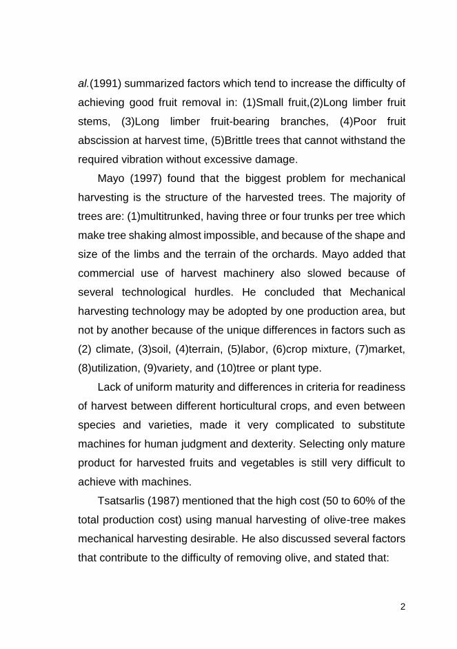
al.(1991) summarized factors which tend to increase the difficulty of
achieving good fruit removal in: (1)Small fruit,(2)Long limber fruit
stems, (3)Long limber fruit-bearing branches, (4)Poor fruit
abscission at harvest time, (5)Brittle trees that cannot withstand the
required vibration without excessive damage.
Mayo (1997) found that the biggest problem for mechanical
harvesting is the structure of the harvested trees. The majority of
trees are: (1)multitrunked, having three or four trunks per tree which
make tree shaking almost impossible, and because of the shape and
size of the limbs and the terrain of the orchards. Mayo added that
commercial use of harvest machinery also slowed because of
several technological hurdles. He concluded that Mechanical
harvesting technology may be adopted by one production area, but
not by another because of the unique differences in factors such as
(2) climate, (3)soil, (4)terrain, (5)labor, (6)crop mixture, (7)market,
(8)utilization, (9)variety, and (10)tree or plant type.
Lack of uniform maturity and differences in criteria for readiness
of harvest between different horticultural crops, and even between
species and varieties, made it very complicated to substitute
machines for human judgment and dexterity. Selecting only mature
product for harvested fruits and vegetables is still very difficult to
achieve with machines.
Tsatsarlis (1987) mentioned that the high cost (50 to 60% of the
total production cost) using manual harvesting of olive-tree makes
mechanical harvesting desirable. He also discussed several factors
that contribute to the difficulty of removing olive, and stated that:
3
The olive is small fruit attached strongly to the limb. As a result, the
ratio of removal force to weight (f/w) is high.
Fruit is generally born on long willowy branches which hang
downward isolating fruit from applied vibration forces.
The tree structure is also willowy. Many trees are old and have
brittle branches weakened by disease or grafts.
A further difficulty is that many trees have been cultivated on hilly
or mountainous areas making the mechanization difficult.
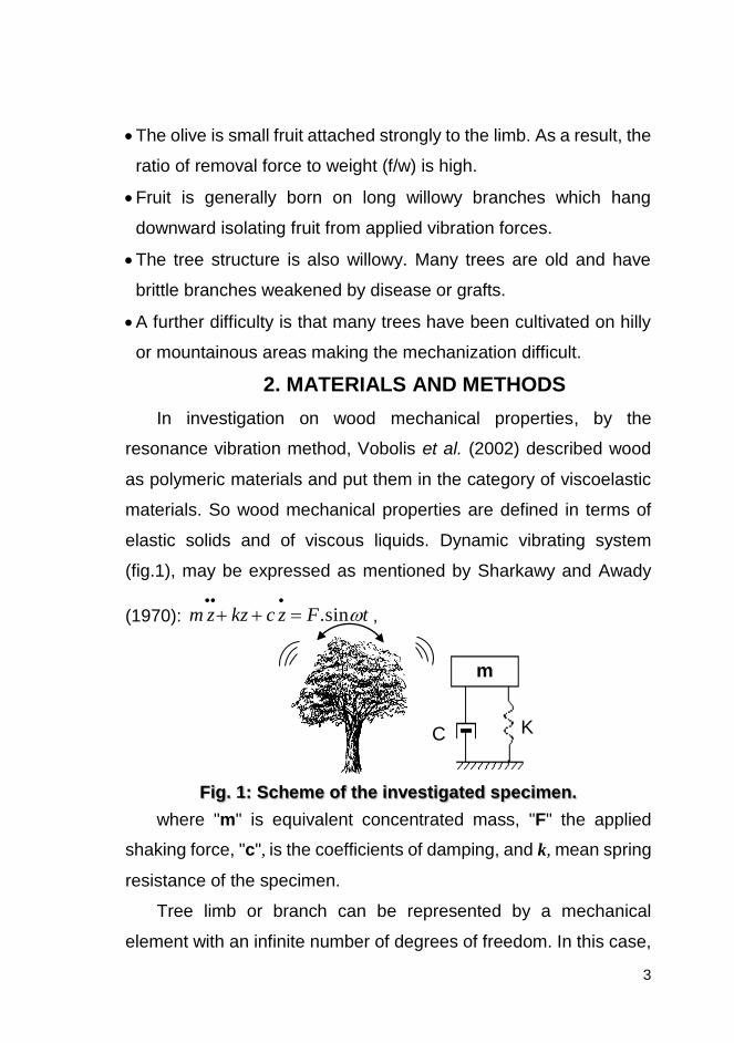
2. MATERIALS AND METHODS
In investigation on wood mechanical properties, by the
resonance vibration method, Vobolis et al. (2002) described wood
as polymeric materials and put them in the category of viscoelastic
materials. So wood mechanical properties are defined in terms of
elastic solids and of viscous liquids. Dynamic vibrating system
(fig.1), may be expressed as mentioned by Sharkawy and Awady
(1970): tFzckzzm sin.
,
Fig. 1: Scheme of the investigated specimen.
where "m" is equivalent concentrated mass, "F" the applied
shaking force, "c", is the coefficients of damping, and k, mean spring
resistance of the specimen.
Tree limb or branch can be represented by a mechanical
element with an infinite number of degrees of freedom. In this case,
K C
m
K C
m

4
the mass of the bar is also distributed along its length, and its
transverse oscillations equation can be written as reviewed by
Vobolis et al.,(2003): 02
2
4
4
tEI
zS
x
z (This equation is not
general equation) tfuKuCuM where is the
density of wood, S is the cross-sectional area of the bar, E is the
modulus of elasticity, I is the moment of inertia of the cross section,
and x, z are oscillation coordinates.
By solving this equation, an infinite sequence of frequencies is
obtained. The basic frequency of free vibration is calculated as:
352.3
mL
EIf where E is the modulus of elasticity, I is the moment
of inertia of the cross-section, f is frequency of the mass free
oscillations, L is length of the element, m is mass of the element.
The natural frequency is determined according to the
relationship: m
kfn reviewed by El Attar et al., (2004). where
"k" is the appropriate elasticity value (spring rate) "m" is the
appropriate mass value (fig.2).
Fig. 2: The model of olive-fruit vibratory system.
SIMULATING TREE SHAKER HARVESTER:
SAP2000, an "Integrated Finite Element Analysis and Design of
Structures" computer software tool, was used to represent, analyze,
and simulate the olive-tree model structure as illustrated in fig(3).
Olive fruit
Spur
5
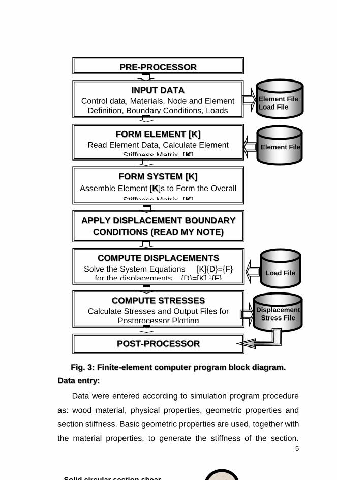
Fig. 3: Finite-element computer program block diagram.
Data entry:
Data were entered according to simulation program procedure
as: wood material, physical properties, geometric properties and
section stiffness. Basic geometric properties are used, together with
the material properties, to generate the stiffness of the section.
PRE-PROCESSOR
INPUT DATA
Control data, Materials, Node and Element Definition, Boundary Conditions, Loads
FORM ELEMENT [K]
Read Element Data, Calculate Element
Stiffness Matrix, [K]
FORM SYSTEM [K]
Assemble Element [K]s to Form the Overall
Stiffness Matrix, [K]
APPLY DISPLACEMENT BOUNDARY
CONDITIONS (READ MY NOTE)
COMPUTE DISPLACEMENTS
Solve the System Equations [K]{D}={F} for the displacements {D}=[K]-1{F}
COMPUTE STRESSES
Calculate Stresses and Output Files for Postprocessor Plotting
POST-PROCESSOR
Element File
Load File
Element File
Load File
Displacement
Stress File
Solid circular section shear
2r 9.0 areashearEffective

6
Elements of the cross-sectional area, and the moment of inertia are
shown in fig.(4).
Fig. 4: Corresponding bending stiffness of the Section.
Formulae for calculating the shear areas of typical sections are
given in: (1)Tree frame-elements, representing trunk, branches,
leaves, and fruit, (2)Joints that represent connections of tree
elements, (3)Restraints and springs that support the joints, and
(4)Loads, including self-weight (wood, stem, leave, and fruit mass),
vibration force, and others. After analyzing tree skeleton, the model
also includes displacements, stresses, and reactions due to the
loads.
Model description: (Fundamental Assumptions)
Data were recorded over a short period of time "1sec", so that the
properties of the limb were assumed constant throughout the test
period.
Tree structure was evaluated for steady-state forced vibration.
Tree limb elements were considered to be truncated conic
segments, with length and radius of curvature very large compared
to their diameter.
The tree was simulated by a number of elements that formulate a
trunk with three branches for simplicity, each supporting secondary
branches which support fruits in return.
Un-damped mode shapes and natural frequencies were found
using the "Eigenvector" analysis procedure, considering
proportional damping
Rotary inertia and shear effects are neglected.
7
External damping was neglected (This part will bring a lot of
criticism to your work. Are you sure we do not have any damping?
I guess we neglected the external damping for eigen value analysis
only not for external excitation model).
Deflection and loads occurred in a three dimensional space.
Olive-tree model considered Z direction as the vertical axis, with
+Z being upward. Local coordinate systems for joints, elements, and
ground-acceleration loading are defined with respect to this upward
direction. Self-weight loading (wood, leaves, and fruits) always acts
downward.
Definitions: Definitions are set to create named entities that are not
part of the geometry of the model. These entities include:
Material properties: Material properties of olive-tree wood which
are mainly: (a) mass per unit volume, (b) mass per unit volume, and
(c) modulus of elasticity.
Mass Density, Mass density, w, is used for calculating the self-
weight "Ws" of the element. The total weight of the element is
VWWs , Where "V" is the volume of the element.
This weight is apportioned to each joint of the element. Self-
weight is activated using Self-weight Load and Gravity Load.
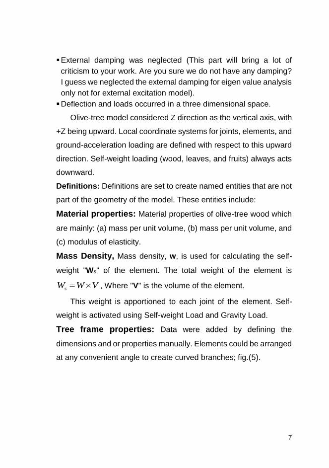
Tree frame properties: Data were added by defining the
dimensions and or properties manually. Elements could be arranged
at any convenient angle to create curved branches; fig.(5).
8
Fig. 5: Frame section "truncated cone" definition.
(SAP2000 Software)
Model analysis:
Completing structural model, and operations above were used
to determine the resulting displacements, stresses, and reactions.
However, before analyzing, options must be set up for the tree
model including the following:
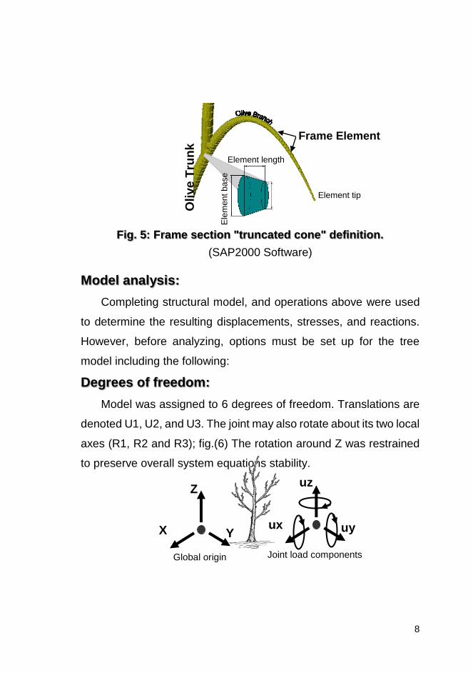
Degrees of freedom:
Model was assigned to 6 degrees of freedom. Translations are
denoted U1, U2, and U3. The joint may also rotate about its two local
axes (R1, R2 and R3); fig.(6) The rotation around Z was restrained
to preserve overall system equations stability.
Olive T
run
k Frame Element
Element length
Ele
men
t ba
se
Element tip
Joint load components Global origin
Z
X Y
uz
ux uy

9
Fig. 6: The six degrees of freedom in the joint local
coordinate system.
Model Damping:
Proportional modal damping is assumed with respect to the total
stiffness matrix, K, which includes the effective stiffness from the
nonlinear elements
One-dimensional spring system:
Fig.(7) illustrates the fundamentals of finite element method
analysis in one-dimensional spring system by Sap2000 manual
(Better refer to a FEM book not SAP. This is general idea about
FEM). When applying F force at node (3). To find the node
displacement and spring forces, a general element must be
formulated. Element p with nodes i and j, assumes positive
displacement components of ui, at node i and uj at node j. the
element spring constant k, and forces at node result, when these
displacements occur.
When force fip acts on node i due to the node displacements of
element p it could be illustrated at equilibrium form

10
Fig. 7: One-dimensional spring (a)structure, (b) element.
jpippj
jpipip
ukukf
ukukf
And it could be solved according to matrix form as
pj
ip
j
i
pp
pp
f
f
u
u
kk
kk , and fdk
where [k] is the element stiffness matrix, {d} is the element node
displacement vector, and {f} is the element node internal force vector
332
22221
111
0 3 nodeat
0 2 nodeat
0 1 nodeat
Ffforces
Fffforces
Ffforces
Eigenvector analysis used by simulation software, determines
the undamped free-vibration mode shapes and frequencies of the
system. These natural modes provide an excellent insight into the
behavior of structures. They can also be used as the basis for
response-spectrum analyses; eigenvector analysis involves the
solution of the generalized eigenvalue problem: 0 MK
where K is the stiffness matrix, M is the diagonal mass matrix; is
the diagonal matrix of eigenvalues, is the matrix of eigenvectors s
mode shapes.
The modes are identified by numbers from 1 to 40 in the order
in which the modes are found by the program. The Eigenvalue is the
square of the circular frequency, for that Mode. The cyclic
(a) (b)

11
020406080
0-100
100-200
200-300
Heig
hts
ab
ov
e g
rou
nd
"cm
"
Leaves mass distribution % Fruit mass %
frequency, f, and period, T, of the Mode are related to by:
2
1 fand
fT
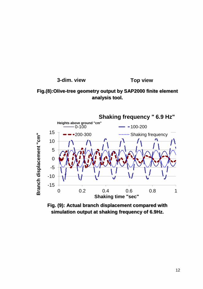
4-RESULTS AND DISCUSSION Data of olive-tree geometry, wood physical properties, masses
of different tree parts, and load distribution are represented in fig.(8).
SAP2000 analysis results (fig.9), agreed with results of field studies
(fig.10), reviewed by El Attar et al. (2004). Analysis has indicated
that: (1)it is impossible to determine a unique optimum applied
frequency or even to choose a very narrow frequency range that is
particularly effective in tree harvesting, (2)simulation results, also
emphasize the tree clamping point to be at 40 cm above ground as
indicated from fig.(11), (3)tree must be trained and pruned in vase-
shape to increase the harvesting efficiency and to avoid developed
fruit near the ground. Tree harvesting electronic model and
simulation is capable of similar different tree harvesting actions for
different tree types and analysis of the results establish roles of
designing and constructing tree harvester mechanisms.
Elevation
12
Fig.(8):Olive-tree geometry output by SAP2000 finite element
analysis tool.
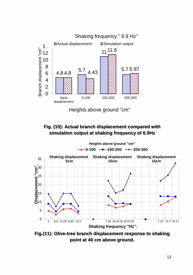
Fig. (9): Actual branch displacement compared with
simulation output at shaking frequency of 6.9Hz.
-15
-10
-5
0
5
10
15
0 0.2 0.4 0.6 0.8 1
Bra
nc
h d
isp
lac
em
en
t "c
m"
Shaking time "sec"
Shaking frequency " 6.9 Hz"
0-100 100-200
200-300 Shaking frequency
Heights above ground "cm"
Top view 3-dim. view
13
Fig. (10): Actual branch displacement compared with
simulation output at shaking frequency of 6.9Hz
Fig.(11): Olive-tree branch displacement response to shaking
point at 40 cm above ground.
4.85.7
11
5.74.8 4.43
11.6
5.97
0
2
4
6
8
10
12
14
Inputdisplacement
0-100 100-200 200-300
Bra
nch
dis
pla
cem
ent "c
m"
Heights above ground "cm"
Shaking frequency " 6.9 Hz"
Actual displacement Simulation output
0
5
10
15
20
25
30
35
5 6.9 8.125 8.83 10.2 7.36 10.44 16.15 22.02 7.23 14.7 20.17
Dis
pla
ce
me
nt
"c
m".
Shaking frequency "Hz".
0-100 100-200 200-300
Shaking displacement5cm
Shaking displacement10cm
Shaking displacement 15cm
Heights above ground "cm"
14
5- CONCLUSIONS The developed simulation model of tree harvesting based on
finite element analysis agreed with the field tests. Simulation model
analysis showed that tree response varied with different shaking
actions according to fruit location on the olive-tree due to differences
in physical and mechanical properties. Concluded
recommendations of simulating harvesting cases are:
1. Tree must be trained and pruned in vase-shape to limit the
branches in the bottom portion of the olive-tree giving inefficient
properties for fruit removal by shaking.
2. Attaching the clamping device of the tree shaker harvester at
height 40cm above the ground gives good results of shaking
olive-tree branches giving high fruit removal.
3. Using simulation model for other conditions of tree harvesting is
foreseen by applying changes to values of physical properties,
tree skeleton, stiffness, and mass distribution.
This study iterates demand for further studies or simulating
the changes in the physical properties for different tree
developing stages by environmental, climatic, and biological
factors, etc...
REFERENCES
El Attar, M.Z.; El Awady, M.N.; Rashwan, M.; M.A.I. Genaidy., 2004, Physical properties effects on shaker-model harvesting of olive-trees, 10th MSAE conf.:
Fridley, R.B.; Adrian, P.A.; Claypool, L.L.; Rizzi, A.D.; and Leonard, S.J., 1991, Mechanical harvesting of cling peaches. Calif. Ag. Exp. Sta., Bull: 851.
15
Mayo, D.,1997, Mechanical harvesting, Adapted from Australian Olive Grower, Olive Agencies, 16 McGarva Rd, Grantham Q4347, Australia. (http://www.oliveaustralia.aust.com)
SAP2000 manual,2000 , SAP2000 an Integrated Finite Element Analysis and Design of Structures,
Sharkawy, M.K. ; and Awady, M.N. , 1970, Theory of machine, Ain-Shams Press: 321-324
Tsatsarelis; C.A., 1987, Vibratory olive harvesting: The response of the fruit-stem system to fruit removing action, J. Agric. Eng., 83:77-90.
Vobolis, J.; and Aleksiejunas, M., 2003, Investigation of wood mechanical proparties by the resonance vibration method, ISSN 1392-1320 Materials Scie., 9(1):139-142.

16
محاكاة هز األشجار بواسطة نموذج الكترونى (3)، العطار، م.ز.(2)، تاج الدين ، ح.(1)العوضى، م.ن.
البحث صلخستم
جرى محاكاة حصاد األشجار بالهز. لذا تم تكوين نموذج الكترونى يعتمد على
( لتحليل العناصر المحدودة فى تقييم المنشآت. وتمثل SAP2000نهج )برنامج
المعطيات لهذا النهج تقريبا للخصائص الطبيعية لشجرة الزيتون، واستجابتها
نتائج المحاكاة والدراسات الحقلية. وأظهرت هذه النتائج ما اتفقتلالهتزاز. وقد
ارتفاع( أمثل 2) ( عدم إمكان تحديد تردد أمثل بعينة للحصاد االهتزازى ،1يلى: )
لنقطة الربط على األشجار وتقليمها على شكل "كأس مفرغ" لزيادة كفاءة الحصاد
أن المحاكى وأتضحالمنخفض على الشجرة قرب األرض. راألثمابتفادى
االهتزاز ألنواع األشجار، وتحليل النتائج أوجهااللكترونى قادر على تمثيل مختلف
الهتزازية.لتصميم وتطوير آليات الحصاد ا
( أ. متفرغ، هندسة زراعية، ك.الزراعة، ج. عين شمس، 1) ( مدرس، هندسة مدنية، ك. الهندسة، ج. القاهرة،2) ( مدرس، هندسة زراعية، ك. الزراعة، ج. عين شمس.3)
17
General comments: 1- I think the fonts are very big and also margins. Try to specify
the Journal name and reshape the paper in their format 2- Make all sentences in present form 3- Do not say a name of a commercial program like SAP2000.
Please replace it with “Structural Analysis software”. The program SAP2000 is the least among tens of advanced structural analysis software. If you like to say it, just once is sufficient inside the context with reference to it as you did
4- Note that you draw a picture of mass-spring model. I am afraid the reader think this is what we did. We are using multi-degree of freedom lumped mass system. It is better also to write the general dynamic equation we use for analysis
5- Figure 3 is very important. Can we illustrate it in more details inside the text.
6- This equation tfuKuCuM is the one
we used for our simulation. So, it is better to state it clearly and define its terms. Most of equations you are stating are for Eigen Value analysis to obtain the tree frequencies which is correct. But for solving the tree for a specific input displacement history, we used this equation
7- We should state more words about the way you applied the load by exciting the base of the tree. It is a great part of your work
8- Please state more details about the FEM analysis we did for example:
a. Number of frame elements b. Number of joints c. Number of degrees of freedom (6 * number of joints) d. Number of cross sections
9- When you talk about One Dimensional spring-mass model, it will confuse the reader about what we did. We did 3-D FEM model using frame elements not 1-D models using series of mass-springs
10- In brief, re arrange the paper to be 1- review about what people did, review about FEM model and eigen value calculations, talk about our model in SAP with more details about joints, elements, etc. We have two models with SAP, one for Eigen value analysis and one for external excitation, right? Make that very clear

18
11- Finally, reduce the fonts to be 10 Arial for text and 12 for titles and reduce the margins to be 2.5 cm from all directions
Copyright © 2022 FDOKUMEN