
Design and verification challenges of hydropower plant caverns
9
Design and verification challenges of hydropower plant caverns T. Marcher and E. Saurer ILF Consulting Engineers Ltd Feldkreuzstrasse 3 6063 Rum / Innsbruck Austria The demand for pumped storage plants that store energy and cover peak current has been increasing significantly in recent years. Power plant caverns with cross-sectional areas of >1500 m² are constructed in an increasing number. From a rock mechanics perspective, this implies that excavation and support of caverns in rock become more challenging. Among other boundary conditions this is due to the size of caverns, complexity of access tunnels, geological conditions and due to tighter schedules for design and construction. Existing correlations concerning decisive parameters for the design of power caverns are used to discuss the design of caverns built in recent years; the parameters include capacity, net water head, cavern geometry, overburden height above the cavern and typical rock parameters. Subsequently, cavern shapes as well as the criteria which have to be considered for the size of the rock pillar between two caverns are considered in detail. This paper describes recent experience with cavern constructions and compares this experience with the correlations from literature. Fig. 1. Example of an underground structure in the vicinity of a power plant cavern with machine and transformer caverns and tunnels for construction, access, operation and installation of support in a cavern [Error! Reference source not found.]. 1. Correlations of Decisive Parameters for Caverns A data set to evaluate decisive parameters for power plant caverns is presented in Saurer et al.[2]. Different dependencies between decisive parameters have been investigated. The shown dependencies between capacity of the hydropower plant and the geometry of the main cavern can be used as a first assessment at an early design stage for power storage plants or may serve to cross check defined geometries. Furthermore, dependencies between cavern geometry and geotechnical properties have been analysed with respect to expected deformations at the crown or sidewalls, and a comparison has been made between cavern supports as a function of rock properties and cavern size. 2. Power Plant Caverns – Reference Projects The main focus of the paper is on presenting recent experience with cavern constructions and compare this experience with the correlations described in the previous chapter. Hence, relevant project data of chosen reference projects are listed below. 2.1 Limmern Caverns The project Linthal 2015 encompasses an upgrade of the existing power stations and the construction of a high- capacity pumped-storage plant. This 1,000 MW pumped-storage plant is under construction at altitudes between 1,600 and 2,400 m.a.s.l. in the Glarner Alps of Switzerland, around 90 km south-east of Zurich. The new
-
Upload
khangminh22 -
Category
Documents
-
view
2 -
download
0
Transcript of Design and verification challenges of hydropower plant caverns
Design and verification challenges of hydropower plant caverns
T. Marcher and E. Saurer ILF Consulting Engineers Ltd Feldkreuzstrasse 3 6063 Rum / Innsbruck Austria The demand for pumped storage plants that store energy and cover peak current has been increasing significantly in recent years. Power plant caverns with cross-sectional areas of >1500 m² are constructed in an increasing number.
From a rock mechanics perspective, this implies that excavation and support of caverns in rock become more challenging. Among other boundary conditions this is due to the size of caverns, complexity of access tunnels, geological conditions and due to tighter schedules for design and construction.
Existing correlations concerning decisive parameters for the design of power caverns are used to discuss the design of caverns built in recent years; the parameters include capacity, net water head, cavern geometry, overburden height above the cavern and typical rock parameters.
Subsequently, cavern shapes as well as the criteria which have to be considered for the size of the rock pillar between two caverns are considered in detail. This paper describes recent experience with cavern constructions and compares this experience with the correlations from literature.
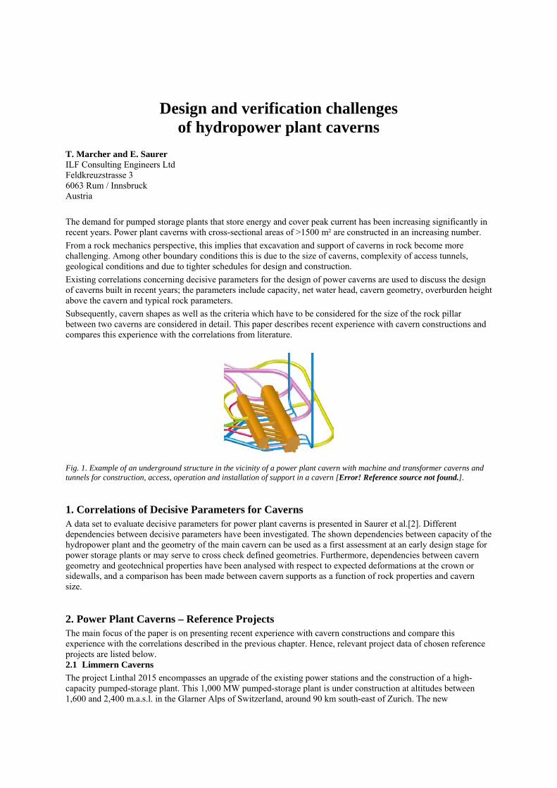
Fig. 1. Example of an underground structure in the vicinity of a power plant cavern with machine and transformer caverns and tunnels for construction, access, operation and installation of support in a cavern [Error! Reference source not found.]. 1. Correlations of Decisive Parameters for Caverns A data set to evaluate decisive parameters for power plant caverns is presented in Saurer et al.[2]. Different dependencies between decisive parameters have been investigated. The shown dependencies between capacity of the hydropower plant and the geometry of the main cavern can be used as a first assessment at an early design stage for power storage plants or may serve to cross check defined geometries. Furthermore, dependencies between cavern geometry and geotechnical properties have been analysed with respect to expected deformations at the crown or sidewalls, and a comparison has been made between cavern supports as a function of rock properties and cavern size. 2. Power Plant Caverns – Reference Projects The main focus of the paper is on presenting recent experience with cavern constructions and compare this experience with the correlations described in the previous chapter. Hence, relevant project data of chosen reference projects are listed below. 2.1 Limmern Caverns
The project Linthal 2015 encompasses an upgrade of the existing power stations and the construction of a high-capacity pumped-storage plant. This 1,000 MW pumped-storage plant is under construction at altitudes between 1,600 and 2,400 m.a.s.l. in the Glarner Alps of Switzerland, around 90 km south-east of Zurich. The new
underground facility will pump water from lake Limmern 630 m back up to lake Mutt. This will boost the Linth Limmern (owned by the Linth Limmern AG) power plant`s output from currently 450 MW to 1,450 MW.
The machine and the transformer caverns are situated in Quintner Limestone with an overburden of 400 to 500 m. The 150 m long machine cavern has a maximum height of 56 m and a width of approximately 30 m. Transformers are located in a separate cavern parallel to the machine cavern.
For details see [3] and [4].
2.2 Limberg II Caverns
The Limberg II pumped-storage plant (PSP) has been constructed parallel to the existing power station and increases capacity of the Glockner-Kaprun power station group in 480 MW. The new power station consists of two reversible pump turbines constructed underground. The new Limberg II pumped-storage plant started operation in 2011 by using the difference in height between the Mooserboden and Wasserfallboden annual storage reservoirs.
The construction took place at altitudes between 850 and 2,050 m.a.s.l. in the Central Alps of Austria, around 75 km southwest of Salzburg. The machine and the transformer caverns are situated in the Glocknerfazies (part of the penninische Tauernfenster) consisting predominantly of Grünschiefer and Bündner Schiefer with an overburden of approx. 500 m. The machine cavern is a longitudinal structure with a maximum length of 62 m, a width of approx. 25 m and a maximum height of 43 m. The transformer cavern is smaller and situated parallel to the machine cavern on an axial distance of approx. 51 m.
For details see [5] and [6].
2.3 Atdorf Caverns
The Atdorf Pumped-Storage Plant is situated on the southern border of the Black Forest and belongs to Schluchseewerk Ltd, which also operates the existing Wehr PSP and Säckingen PSP. With a planned overall capacity of 1,400 MW, it will use the 600 m difference in height between the Hornberg mountain and the Haselbachtal valley on a 9.4 km long section.
The new cavern will be close to the cavern of the existing Wehr Pumped-Storage Plant. The machine and the transformer caverns are situated in granite-porphyr with an overburden of approx. 750 m. The machine cavern has a height of 53 m and a width of approximately 27 m and can accommodate 6 machine groups. Transformers are located in a separate cavern parallel to the machine cavern. For details see [1]. 3. Interpretation of Results 3.1 Cavern Shape
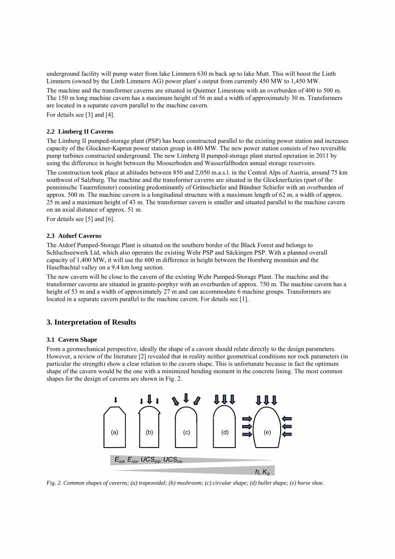
From a geomechanical perspective, ideally the shape of a cavern should relate directly to the design parameters. However, a review of the literature [2] revealed that in reality neither geometrical conditions nor rock parameters (in particular the strength) show a clear relation to the cavern shape. This is unfortunate because in fact the optimum shape of the cavern would be the one with a minimized bending moment in the concrete lining. The most common shapes for the design of caverns are shown in Fig. 2.
(a) (b) (c) (d) (e)
h, K0
Eint, Erm, UCSint, UCSrm
Fig. 2. Common shapes of caverns; (a) trapezoidal; (b) mushroom; (c) circular shape; (d) bullet shape; (e) horse shoe.

Generally, flat roofs and vertical sidewalls as shown in Fig. 2 (a-c) are preferred for economic reasons (reduced excavation volume, smaller amount of non-used underground space, simpler excavation stages). In strong rock mass the conventional shape chosen for the cavern may be designed with a rather flat roof and vertical sidewalls. In principle, this is analogous to the ratio of the arch height to the length of arch bridges, which also depends on the stiffness and strength of the rock mass in the abutment. Here, the properties of the arch itself have to be considered since the arched roof provides a higher stability margin in the rock above the cavern.
The problem with cavern shapes as presented in Fig. 2 (a-d) when used in weak rock masses, particularly with high horizontal in-situ stresses, is that tall straight sidewalls may be deflected inwards and tensile failure may be induced. In such caverns, the stabilisation of the rock mass surrounding the cavity will require significant reinforcement in the form of grouted cable anchors or rock bolts. This may be overcome by using a horseshoe cavern shape as illustrated in Fig. 2 (e). The disadvantage of such a shape is that the construction has to be executed in such a way as to ensure greater accuracy of the profile than in the case of a straight-walled cavern. Hence, with an increasing overburden h, it is advantageous to have the machine cavern sidewalls slightly curved in order to avoid high tensile failure zones and to reduce support requirements.
In the case of the Limmern caverns the sidewalls curve slightly inwards in order to obtain a better stress distribution in the rock and to avoid high tensile zones in the sidewalls. The shorter and smaller transformer cavern has vertical sidewalls. The caverns of Limberg II have a horseshoe shape with curved walls and also curved cavern end walls. The machine cavern of Atdorf is to be designed with a higher arch as compared to that of the smaller transformer cavern. Fig. 3 illustrates the cavern shape of the reference projects mentioned in chapter 2.
Fig. 3. Cavern shapes of the reference projects. 3.2 Pillar width between caverns
Transformers are frequently located in a separate cavern parallel to the power cavern (see also reference projects, Fig. 3). In this context, the width of the rock pillar separating the two caverns is a critical design element. In addition the arrangement of tailrace, access and cable galleries intersecting the rock pillar between the caverns (see e.g. Fig. 1) reduce the overall strength of the pillar.
As a design rule, the zone of overstressing in the rock pillar shall be kept as small as possible both as regards tension and compression.
Marcher et al. [7] and Marclay et al. [8] illustrate results of analyses in which the distance between the Limmern caverns has been varied. The optimization criterion for the distance between the two caverns has been set in such a way that the wall displacements of the already excavated cavern should not increase by more than 10% when the second cavern is excavated.
Finally, the distance between the cavern axes was increased to 82 m to avoid overlapping plastic zones following the evaluation of geological conditions of the pilot tunnel (see Fig. 4).

Fig.4. Development of plastic zones - Limmern cavern axis distance (52 versus 82m) [7].
Due to more competent rock conditions and smaller cavern dimensions, the distance between the cavern axes of the Limberg II storage plant is 51m. 4. Interdependency between geometry and capacity of the cavern Starting with the capacity of the turbines installed in the cavern, dependencies with the geometrical data of the cavity have been analysed. It is assumed that the total (maximum) capacity P of the PSP in hydraulics can be calculated by means of P = p x Q, where p denotes the pressure and Q is the volumetric flow. Besides the annual electricity production, which is not considered in this paper, the maximum capacity is the main specification factor for power plants
While the dependency between the capacity and the volume of the cavern is promising (see Fig. 5, left plot), it has been found that for the cross sectional area (B x H) and the area of the cavern (L x B) dimensions do not depend exclusively on the installed capacity. However, as shown in Fig. 5, right side, the cavern height seems to have a correlation with the capacity. Please note that for simplicity, in the data set the volumes have been calculated using B x H x L, i.e. the excavation volume tends to be overestimated. For the data of the reference projects the correlations fit well.
Atdorf
Linth - Limmern
Limberg 2
Limberg 2
Atdorf
Linth - Limmern
Limberg 2
Fig. 5. Dependency between capacity and cavern volume (left – with a proposed linear regression curve of the formula y=ax+b) and capacity and cavern height (right side – with a proposed exponential regression curve of the formula y=aebx).
Another attempt to find a dependency between production and cavern size has been made by dividing the capacity P by the net water head hnet. In this regard, the net water head hnet is the factor which influences the pressure p, which is calculated by p = hnet x γw, where γw is the unit weight of water.
An advantage of using the net water head is that this parameter can easily be found in the literature and, for a rough estimate, it can be related linearly to the pressure p. The equation shown above results in P/ (hnet) = Q x γw. Due to
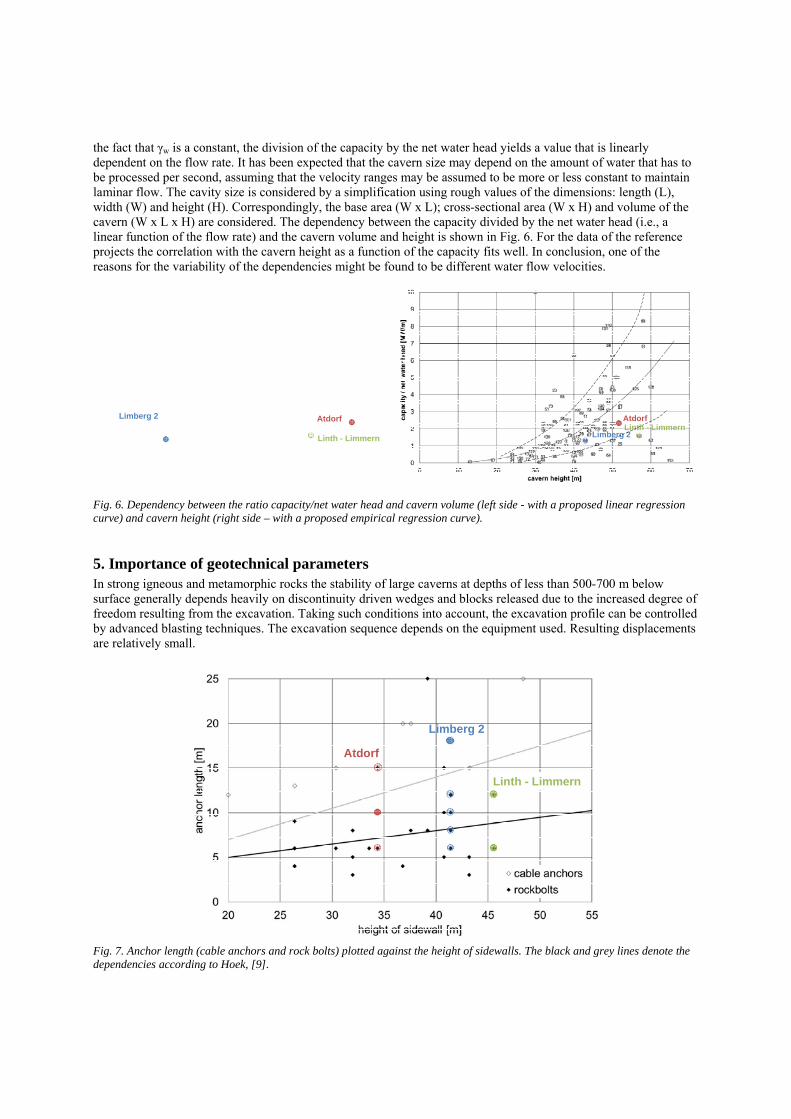
the fact that γw is a constant, the division of the capacity by the net water head yields a value that is linearly dependent on the flow rate. It has been expected that the cavern size may depend on the amount of water that has to be processed per second, assuming that the velocity ranges may be assumed to be more or less constant to maintain laminar flow. The cavity size is considered by a simplification using rough values of the dimensions: length (L), width (W) and height (H). Correspondingly, the base area (W x L); cross-sectional area (W x H) and volume of the cavern (W x L x H) are considered. The dependency between the capacity divided by the net water head (i.e., a linear function of the flow rate) and the cavern volume and height is shown in Fig. 6. For the data of the reference projects the correlation with the cavern height as a function of the capacity fits well. In conclusion, one of the reasons for the variability of the dependencies might be found to be different water flow velocities.
Atdorf
Linth - Limmern
Limberg 2 AtdorfLinth - Limmern
Limberg 2
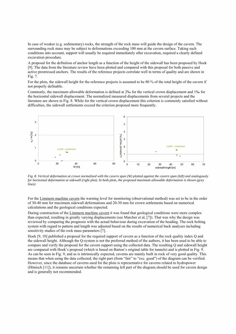
Fig. 6. Dependency between the ratio capacity/net water head and cavern volume (left side - with a proposed linear regression curve) and cavern height (right side – with a proposed empirical regression curve). 5. Importance of geotechnical parameters In strong igneous and metamorphic rocks the stability of large caverns at depths of less than 500-700 m below surface generally depends heavily on discontinuity driven wedges and blocks released due to the increased degree of freedom resulting from the excavation. Taking such conditions into account, the excavation profile can be controlled by advanced blasting techniques. The excavation sequence depends on the equipment used. Resulting displacements are relatively small.
Atdorf
Linth - Limmern
Limberg 2
Fig. 7. Anchor length (cable anchors and rock bolts) plotted against the height of sidewalls. The black and grey lines denote the dependencies according to Hoek, [9].
In case of weaker (e.g. sedimentary) rocks, the strength of the rock mass will guide the design of the cavern. The surrounding rock mass may be subject to deformations exceeding 100 mm at the cavern surface. Taking such conditions into account, support will usually be required immediately after excavation, required a clearly defined excavation procedure.
A proposal for the definition of anchor length as a function of the height of the sidewall has been proposed by Hoek [9]. The data from the literature review have been plotted and compared with this proposal for both passive and active prestressed anchors. The results of the reference projects correlate well in terms of quality and are shown in Fig. 7.
For the plots, the sidewall height for the reference projects is assumed to be 80 % of the total height of the cavern if not properly definable.
Commonly, the maximum allowable deformation is defined at 2‰ for the vertical crown displacement and 1‰ for the horizontal sidewall displacement. The normalized measured displacements from several projects and the literature are shown in Fig. 8. While for the vertical crown displacement this criterion is commonly satisfied without difficulties, the sidewall settlements exceed the criterion proposed more frequently.
Linth - Limmern
Fig. 8. Vertical deformation at crown normalized with the cavern span (W) plotted against the cavern span (left) and analogously for horizontal deformation at sidewall (right plot). In both plots, the proposed maximum allowable deformation is shown (grey lines)
For the Limmern machine cavern the warning level for monitoring (observational method) was set to be in the order of 30-40 mm for maximum sidewall deformations and 20-30 mm for crown settlements based on numerical calculations and the geological conditions expected.
During construction of the Limmern machine cavern it was found that geological conditions were more complex than expected, resulting in greatly varying displacements (see Marcher et al, [7]). That was why the design was reviewed by comparing the prognosis with the actual behaviour during excavation of the heading. The rock bolting system with regard to pattern and length was adjusted based on the results of numerical back analyses including sensitivity studies of the rock mass parameters [7].
Hoek [9, 10] published a proposal for the required support of cavern as a function of the rock quality index Q and the sidewall height. Although the Q-system is not the preferred method of the authors, it has been used to be able to compare and verify the proposal for the cavern support using the collected data. The resulting Q and sidewall height are compared with Hoek’s proposal (which is based on Barton’s original table for tunnels) and is plotted in Fig. 9. As can be seen in Fig. 9, and as is intrinsically expected, caverns are mainly built in rock of very good quality. This means that when using the data collected, the right part (from “fair” to “exc. good”) of the diagram can be verified. However, since the database of caverns used for the plots is representative for caverns related to hydropower (Hönisch [11]), it remains uncertain whether the remaining left part of the diagram should be used for cavern design and is generally not recommended.
Linth - Limmern

exceptionallypoor
extremelypoor very poor poor fair good
very good
ext. good
exc. good
no precedent experience
no support required
Fig. 9. Comparison of data referred to in this paper with the experiences for support proposed by Hoek [9, 10]. 6. Summary Existing correlations concerning decisive parameters for the design of power caverns are used to discuss the design of reference caverns built in recent years, including parameters such as capacity, net water head, cavern geometry, overburden height above the cavern and typical rock parameters.
It has been shown that most caverns are built in very good rock. By being aware of geomechanical and geometrical interactions, the design of the cavern shape might be optimized in order to further reduce the risk of failures and to minimize the cost for support.
The data shown here represent a range of possible dependencies. The data provided shall provide plots to get a first idea of the size and expected behaviour of the cavern and does not replace the required fundamental analysis. Continuous collection and implementation of decisive parameters, in particular rock properties, support systems and measured deformation, into the database will further increase the significance of the dependencies.

Appendix: Index of power plants used for correlation of data according to [2] and [11]
1 Agus 4 2 Alberschwende 3 Alto Lindoso 1 4 Anapo 5 Angostura 6 Arimine 7 Atdorf 8 Baglihar 9 Baishan 10 Batoka 11 Berke 12 Bissorte 2 13 Blanda 14 Boundary 15 Brommat 2 16 Carbora Basa S 17 Caraguatatuba 18 Chamera 19 Chibro 20 Churchill Falls 21 Cirata 22 Coo-Trois Ponts 1 23 Dez 24 Dinorwic 25 Dlouhé Strané 26 Drakensberg 27 Dul Hasti 28 Edolo 29 El Cajon 30 Elandsberg 31 Entracque 32 Estangento 33 Fljotsdalur 34 Fortuna 35 Fulpmes 36 Godar-e-Landar 37 Goldisthal 38 Gondar Extension 39 Gordon 40 Grimsel 1 41 Helms 42 Hintermuhr 43 Honkawa 44 Huben 45 Imaichi 46 Inagawa 47 Inguri 48 Kadamparai 49 Kafue Gorge 50 Kariba 51 Kariba Extension 52 Karun 1 Extension 53 Karun 3 54 Kazunogawa 55 Khiritharn 56 Kiambere 57 Kisenyama 58 Kolymsk 59 Kops I 60 Kops II 61 Kukule 62 Lago Delio 63 Lakhwar 64 Langenegg 65 Le Verney 66 Limberg 2 67 Limberg 68 Linth – Limmern 69 Longtan 70 Lubuge 71 Lutz 72 Machu - Picchu 73 Mantaro 3 74 Markersbach 75 Maung 76 Mauvoisin 2 77 Mica 78 Minghu 79 Mingtan 80 Miranda 1 81 Moell 82 Montezic 83 Morrow Point 84 Muela 85 Nabara 86 Nathpa Jhakri 87 Niikappu 88 Northfield 89 Numazawa 2 90 Ohira 91 Okutataragi 92 Okuyahagi 2 93 Okuyoshino 94 Orelle 95 Oroville 96 Paolo Afonso 4 97 Piedilago 98 Poatina 99 Polyphyton 100 Portage Mountain 101 Predikaloszek 102 Prutz – Imst 103 Raccon Mtn 104 Ralco 105 Rangipo 106 Reißeck II 107 Revin 108 Rio Grande 1 109 Riul Mare 110 Säckingen 111 Salamonde 112 Samrangjin 113 San Fiorano 114 sardar sarovar 115 Saussaz 2 116 Sayan 117 Shimogo 118 Shintakasegawa 119 Siah Bishe 120 Siguragura 121 Sisteron 122 Taloro 123 Tamahara 124 Techi 125 Tehri 1 126 Timpagrande 127 Tumut 1 128 Tumut 2 129 Turlough Hill 130 Uri Hydel 131 Ust Khantaisk 132 Vanderkloof 133 varahi 134 Venda Nova 135 Veytaux 136 Vianden 137 Waldeck II 138 Walgauwerk 139 Wehr 140 Who – S Idriss 141 Ertan 142 Ladjanírsk 143 Sima 144 Thissavros
References
1. Arch, A., “Übersicht über derzeitige PSW-Projekte in Europa und Deutschland”, Proceedings, 20. Symposium für Felsmechanik und Tunnelbau, Stuttgart, 2012.
2. Saurer, E., Marcher, T., John, M., “Decisive design and parameters for power plant caverns”, Proceedings, ITA-AITES World Tunnel Congress, Geneva, 2013.
3. Jenni, H., Mayer, C.M., “Project Power Plant Linthal 2015”, Tunnel, Issue 8, 2010.
4. Börker, M., Ammon, C., Frey, D., “Access Adit I for Kraftwerke Linth-Limmern”, Tunnel, Issue 8, 2010.
5. Wagner, E., Hager, A., Blauhut, A., “Pumpspeicherwerk Limberg II”, Felsbau 25, Issue 5, 2007.
6. Schorn, R., “Lösung besonderer logistischer Herausforderungen bei den Bauarbeiten des Pumpspeicherwerks Limberg II, Kaprun”, mining-geo, Issue. 1, 2012.
7. Marcher, T., John, M., Hohberg, J.-M., Fellner, D., Blank, K., Marclay, R., “Design and Verification Challenges of the Limmern Caverns”, Proceedings, ITA-AITES World Tunnel Congress, Geneva, 2013.
8. Marclay, R., Hohberg, J.M., John M., Marcher, T., “The new Linth-Limmern hydro-power plant – design of caverns under 500 m overburden”, Rock Mechanics in Civil and Environmental Engineering, 2010.
9. Hoek, E., “Large powerhouse caverns in weak rock”, Rock engineering for tunnels, 1999.
10. Hoek, E., “Support for very weak rock associated with faults and shear zones”, Proceedings, International Symposium on Rock Support and Reinforcement Practice in Mining, Kalgoorlie, 1999.
11. Hönisch, K., “The world´s underground hydro power plants in 2010”, Proceedings, International water power & dam construction yearbook, 2010.

The Authors Dr. T. Marcher graduated in civil engineering in Innsbruck and worked as a research and teaching assistant at the University of Stuttgart, where he obtained his PhD in geotechnical engineering in 2001. Since joining ILF in 2002 Dr. Thomas Marcher has been involved in a wide variety of projects in rock and soil mechanics applications for tunnels and underground structures as well as foundation engineering, soil improvement and dam engineering mainly in Europe and Northern America. His actual position is Technical Director for Geotechnical Engineering. Dr. E. Saurer graduated in civil engineering in 2006 and worked as a research and teaching assistant at ETH Zurich, where he obtained his PhD in geotechnical engineering in 2009. Since joining ILF in 2010, he has been involved in a wide variety of projects in dam engineering, rock and soil mechanics as well as tunnel and cavern design mainly in Austria, Germany, Switzerland, Poland and the USA.