Design and implementation of hdl modules and circuits for underwater optical wireless communication
6
Design and Implementation of HDL Modules and Circuits for Underwater Optical Wireless Communication Davide Anguita, Davide Brizzolara, Giancarlo Parodi University of Genova Department of Biophysical and Electronic Engineering Via Opera Pia 11A, Genova ITALY {Davide.Anguita, Davide.Brizzolara, Giancarlo.Parodi}@unige.it www.smartlab.dibe.unige.it Abstract: Underwater wireless optical communication has been used for establish a link between mobile vehi- cles and/or fixed nodes because light, especially in the blue/green region, allows to achieve higher data-rate than acoustical or electromagnetic waves for moderate distances. The here proposed work has the aim to pave the way for diffuse optical communication allowing to support optical communication in an Underwater Wireless Sensor Network of dense-deployed fixed nodes for specific application, such as monitoring and surveillance, for shallow, coastal and inland water in the case of moderate/limited area. The use of light impulse for communication is motivated by the possibility of targeting high data-rate, low-cost and small dimension components. This paper describes an overall vision of the system: a HDL implementation of flexible modules for the management of op- tical communication (based on IEEE 802.15.4 and IEEE 802.11 standard) which target the interface with current terrestrial technology for Wireless Sensor Networks; the design and implementation of circuits for underwater optical point-to-point and planar communication. The preliminary results and design consideration are reported considering also future possible developments. Key–Words: Underwater Wireless Communication, Optical Communication, Physical (PHY) Layer, Medium Ac- cess Control (MAC) Layer 1 Introduction The growing need for underwater systems applied to observation and monitoring has considerably stimu- lated the interest in advancing the technologies for underwater wireless communication applied both for point-to-point communication than to support Under- water Wireless Sensor Networks (UWSNs) [1]. The Wireless Sensor Network (WSN) paradigm, where miniaturized nodes cooperate to build a dis- tributed network for sensing the environment, has greatly improved terrestrial technologies in the last few years but it is difficult to transfer most of the know-how developed for terrestrial devices to their underwater counterparts due to the particular charac- teristics of underwater world. In particular, wireless underwater communication still pose a wide range of problems [3]: the use of acoustic communication is the most common but it has low data-rate, high power consumption and problems related to low propagation speed. The work presented in this paper explores the possibility of using optical communication in Under- water Wireless Sensor Networks (UWSNs) by design- ing flexible modules, devoted to manage optical com- munication, which target the integration of existing available terrestrial technologies for WSN with op- tical circuits specifically implemented to support the generation and reception of light impulses. The use of the alternative solution of optical com- munication, despite reaching shorter distances be- cause of attenuation and scattering, reduces the prob- lem of low-speed diffusion and low data-rate of acous- tical signals. Optical underwater communication has been investigated considering: • the high data-rate, which can range from Mb/s to Gb/s, if laser is employed; • the possibility of using relatively low-power components and circuits equipped with LEDs and photodiodes; • the possibility of targeting relatively small di- mensions and low costs for the communication system; This paper is organized as follows: a brief overview of the main aspects of underwater optical Proceedings of the 9th WSEAS International Conference on TELECOMMUNICATIONS and INFORMATICS ISSN: 1790-5117 132 ISBN: 978-954-92600-2-1
Transcript of Design and implementation of hdl modules and circuits for underwater optical wireless communication
Design and Implementation of HDL Modules and Circuits forUnderwater Optical Wireless Communication
Davide Anguita, Davide Brizzolara, Giancarlo ParodiUniversity of Genova
Department of Biophysical and Electronic EngineeringVia Opera Pia 11A, Genova
ITALY{Davide.Anguita, Davide.Brizzolara, Giancarlo.Parodi}@unige.it
www.smartlab.dibe.unige.it
Abstract: Underwater wireless optical communication has been used for establish a link between mobile vehi-cles and/or fixed nodes because light, especially in the blue/green region, allows to achieve higher data-rate thanacoustical or electromagnetic waves for moderate distances. The here proposed work has the aim to pave the wayfor diffuse optical communication allowing to support optical communication in an Underwater Wireless SensorNetwork of dense-deployed fixed nodes for specific application, such as monitoring and surveillance, for shallow,coastal and inland water in the case of moderate/limited area. The use of light impulse for communication ismotivated by the possibility of targeting high data-rate, low-cost and small dimension components. This paperdescribes an overall vision of the system: a HDL implementation of flexible modules for the management of op-tical communication (based on IEEE 802.15.4 and IEEE 802.11 standard) which target the interface with currentterrestrial technology for Wireless Sensor Networks; the design and implementation of circuits for underwateroptical point-to-point and planar communication. The preliminary results and design consideration are reportedconsidering also future possible developments.
Key–Words: Underwater Wireless Communication, Optical Communication, Physical (PHY) Layer, Medium Ac-cess Control (MAC) Layer
1 Introduction
The growing need for underwater systems applied toobservation and monitoring has considerably stimu-lated the interest in advancing the technologies forunderwater wireless communication applied both forpoint-to-point communication than to support Under-water Wireless Sensor Networks (UWSNs) [1].
The Wireless Sensor Network (WSN) paradigm,where miniaturized nodes cooperate to build a dis-tributed network for sensing the environment, hasgreatly improved terrestrial technologies in the lastfew years but it is difficult to transfer most of theknow-how developed for terrestrial devices to theirunderwater counterparts due to the particular charac-teristics of underwater world. In particular, wirelessunderwater communication still pose a wide range ofproblems [3]: the use of acoustic communication isthe most common but it has low data-rate, high powerconsumption and problems related to low propagationspeed. The work presented in this paper explores thepossibility of using optical communication in Under-water Wireless Sensor Networks (UWSNs) by design-ing flexible modules, devoted to manage optical com-
munication, which target the integration of existingavailable terrestrial technologies for WSN with op-tical circuits specifically implemented to support thegeneration and reception of light impulses.
The use of the alternative solution of optical com-munication, despite reaching shorter distances be-cause of attenuation and scattering, reduces the prob-lem of low-speed diffusion and low data-rate of acous-tical signals. Optical underwater communication hasbeen investigated considering:
• the high data-rate, which can range from Mb/s toGb/s, if laser is employed;
• the possibility of using relatively low-powercomponents and circuits equipped with LEDsand photodiodes;
• the possibility of targeting relatively small di-mensions and low costs for the communicationsystem;
This paper is organized as follows: a briefoverview of the main aspects of underwater optical
Proceedings of the 9th WSEAS International Conference on TELECOMMUNICATIONS and INFORMATICS
ISSN: 1790-5117 132 ISBN: 978-954-92600-2-1
communication and applications of an optical UWSN,a presentation of the current developed modules andcircuits followed by conclusion and future develop-ments.
2 Optical Wireless UnderwaterCommunication
Due to the impossibility of using Radio Frequencies(RF), traditionally wireless underwater communica-tion employs acoustic waves because sound propa-gates well in water and its range can be very long(∼km). However, it has several disadvantages such asnarrow bandwidth and latency in communication dueto the slow speed of acoustic wave in water. For in-stance, at ranges of less than 100 m the data transmis-sion rates of these systems in shallow littoral watersare∼10 kb/s.
Experimental tests have shown that an alterna-tive feasible solution is optical communication espe-cially in blue/green light wavelengths, even if lim-ited to short distances (up to 100 m)[3]. Comparedto acoustic communication it offers a practical choicefor high-bandwidth communication and it propagatesfaster in the water (2.255 x10⁸).
Nevertheless it is affected by different factors totake into account for an efficient design [7]. The at-tenuation of a light beam between two points can bedescribed as in 1 whered1 andd2 are the positions ofthe points.
A = e−k(d1−d2)
(
d1
d2
)2
(1)
In the first term,k is defined ask = a(λ) + b(λ) and itis dependent by the wavelength:a is the term relatedto the absorption of water whileb models the scatter-ing which depends both on light wavelength and tur-bidity. The second term, instead, models the quadraticattenuation.
3 ApplicationsOptical underwater communication is an effective al-ternative to current underwater technology especiallyin some particular environments such as, for instance,shallow, coastal and fresh inland waters where the useof this approach is useful to overcome all the short-comings related to the use of acoustic communica-tion and to allow a wide adoption of underwater mon-itoring systems [9][3]. In particular the possibility oftransferring high amount of data in a limited amountof time reducing power consumption can support thetransmission of short video and pictures for a reliable
monitoring and surveillance. Small dimensions andlow-cost components allow to establish a dense de-ployed networks performing an effective fine grainedsampling in the area of interest. It could be possi-ble, for instance, to perform pollution monitoring andfrequent data collection (water temperature, specificconductivity, pH, turbidity, and possibly oxygen con-centration) and, by using a high-data rate optical link,periodically deliver data reducing the time devoted totransmission and network congestion.
4 System Description
4.1 Design ConsiderationCurrently the PHY Layer and a functions subset ofthe MAC Layer have been described by using anHardware Description Language (HDL), in particularVHDL (Very High Speed Hardware Description Lan-guage), as suggested in [4] [5] .
P r o c e s s i n g
u P F P G A /A S I C
M e m o r y
C o m m u n i c a t i o n
S e n s o r s
P o w e r U n i t
Figure 1: WSN node overview
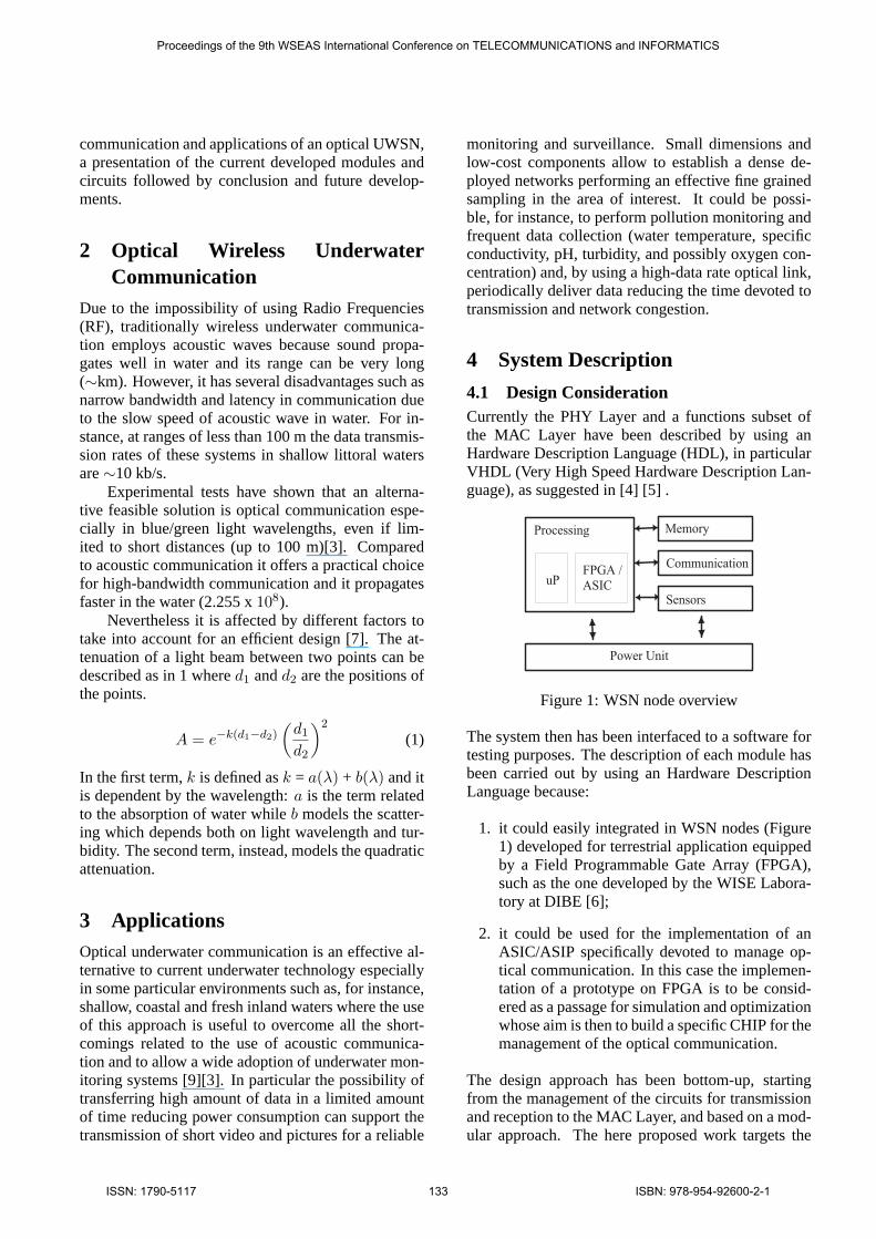
The system then has been interfaced to a software fortesting purposes. The description of each module hasbeen carried out by using an Hardware DescriptionLanguage because:
1. it could easily integrated in WSN nodes (Figure1) developed for terrestrial application equippedby a Field Programmable Gate Array (FPGA),such as the one developed by the WISE Labora-tory at DIBE [6];
2. it could be used for the implementation of anASIC/ASIP specifically devoted to manage op-tical communication. In this case the implemen-tation of a prototype on FPGA is to be consid-ered as a passage for simulation and optimizationwhose aim is then to build a specific CHIP for themanagement of the optical communication.
The design approach has been bottom-up, startingfrom the management of the circuits for transmissionand reception to the MAC Layer, and based on a mod-ular approach. The here proposed work targets the
Proceedings of the 9th WSEAS International Conference on TELECOMMUNICATIONS and INFORMATICS
ISSN: 1790-5117 133 ISBN: 978-954-92600-2-1
interface with current terrestrial technologies and it isinspired to IEEE 802.15.4 for WSN and IEEE 802.11,which supports an optical PHY Layer based on In-fraRed (IR) [8].
MAC Layer - HDL implementation
Packet Parsing
CRC
PD PLME
PHY Layer - HDL implementation
Software Interface
Receiver Transmitter
Optical circuits for Tx and Rx
CSMA/CA
Control Unit
Figure 2: HDL modules overview
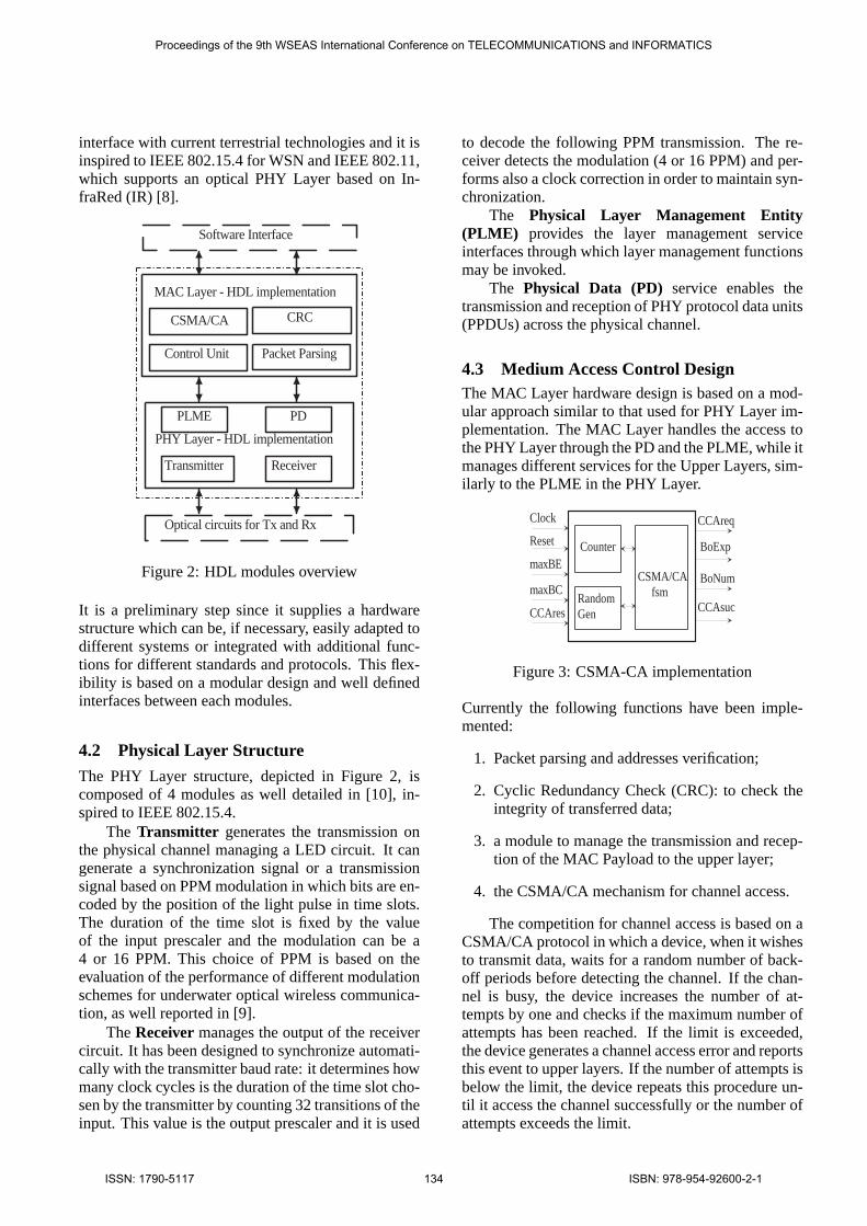
It is a preliminary step since it supplies a hardwarestructure which can be, if necessary, easily adapted todifferent systems or integrated with additional func-tions for different standards and protocols. This flex-ibility is based on a modular design and well definedinterfaces between each modules.
4.2 Physical Layer Structure
The PHY Layer structure, depicted in Figure 2, iscomposed of 4 modules as well detailed in [10], in-spired to IEEE 802.15.4.
The Transmitter generates the transmission onthe physical channel managing a LED circuit. It cangenerate a synchronization signal or a transmissionsignal based on PPM modulation in which bits are en-coded by the position of the light pulse in time slots.The duration of the time slot is fixed by the valueof the input prescaler and the modulation can be a4 or 16 PPM. This choice of PPM is based on theevaluation of the performance of different modulationschemes for underwater optical wireless communica-tion, as well reported in [9].
TheReceiver manages the output of the receivercircuit. It has been designed to synchronize automati-cally with the transmitter baud rate: it determines howmany clock cycles is the duration of the time slot cho-sen by the transmitter by counting 32 transitions of theinput. This value is the output prescaler and it is used
to decode the following PPM transmission. The re-ceiver detects the modulation (4 or 16 PPM) and per-forms also a clock correction in order to maintain syn-chronization.
The Physical Layer Management Entity(PLME) provides the layer management serviceinterfaces through which layer management functionsmay be invoked.
The Physical Data (PD) service enables thetransmission and reception of PHY protocol data units(PPDUs) across the physical channel.
4.3 Medium Access Control DesignThe MAC Layer hardware design is based on a mod-ular approach similar to that used for PHY Layer im-plementation. The MAC Layer handles the access tothe PHY Layer through the PD and the PLME, while itmanages different services for the Upper Layers, sim-ilarly to the PLME in the PHY Layer.
CSMA/CA fsm
Counter
Random Gen
Clock
Reset
maxBE
maxBC
CCAres
CCAreq
BoExp
BoNum
CCAsuc
Figure 3: CSMA-CA implementation
Currently the following functions have been imple-mented:
1. Packet parsing and addresses verification;
2. Cyclic Redundancy Check (CRC): to check theintegrity of transferred data;
3. a module to manage the transmission and recep-tion of the MAC Payload to the upper layer;
4. the CSMA/CA mechanism for channel access.
The competition for channel access is based on aCSMA/CA protocol in which a device, when it wishesto transmit data, waits for a random number of back-off periods before detecting the channel. If the chan-nel is busy, the device increases the number of at-tempts by one and checks if the maximum number ofattempts has been reached. If the limit is exceeded,the device generates a channel access error and reportsthis event to upper layers. If the number of attempts isbelow the limit, the device repeats this procedure un-til it access the channel successfully or the number ofattempts exceeds the limit.
Proceedings of the 9th WSEAS International Conference on TELECOMMUNICATIONS and INFORMATICS
ISSN: 1790-5117 134 ISBN: 978-954-92600-2-1

Figure 4: User interface to optical PHY and MAC Layers
Module Slices %PHY Layer 750 39Trasmitter 154 8Receiver 231 12PLME 173 9PD 192 10MAC Layer 305 16CSMA-CA 190 10others 115 6
Table 1: Implementation on Xilinx Spartan-3 FPGA
The previous described mechanism has been im-plemented in hardware by using a dedicated modulecomposed by a random number generator, for the cal-culation of the random delay, a counter and an othermodule, based on a FSM, to manage the CSMA/CAalgorithm as depicted in Figure 3.
5 ImplementationThe previous described modules have been synthe-sized and implemented on a Xilinx Spartan-3 FPGAand a dedicated program inC# is used to manage theinterface to the Digilent Spartan 3 Board: it allows toperform tests of transmission and set different param-eters of the PHY and MAC Layer (Figure 4).
The VHDL description is developed in genericstandard VHDL and it is planned an integration ina WSN node by using an Actel IGLOO low-powerFPGA which appears to be an effective solution forits low-power and reduced costs.
In Table 1 the results of the implementation onXilinx Spartan-3 FPGA are reported in terms of slices.The maximum frequency that can be achieved by thesystem is 40 MHz.
6 Experimental Testbed
Some circuits implementation and experimental testshave been carried out. They are the basis to implement
a diffuse optical communication which could supporta dense network of small nodes able to exchange dataat high data-rate (in the order of Mb/s). In general ourapproach has focused the possibility of using low-costand low-power components.
In the next paragraph a point-to-point transceiveris described and then a 2-d structure for planar com-munication is proposed.
For point-to-point transceiver tests have been per-formed both in air than underwater by using a specif-ically designed tank. The tank (Figure 5) consists ofa 2 meters long waterproof pipe built of high-densitypolyethylene black plastic.
6.1 Point-to-point communication
The transmitter generates an impulse of light of a fixedduration (250 ns) which allows to support a transmis-sion at 1Mb/s in the case of an 16-PPM modulation orat 2Mb/s in the case of a 4-PPM. The choice of LEDwavelength has been done to maximize the power ofreceived signal as illustrated below (Figure 6).
Particular attention has been posed on the circuitfor the reception, since the reciprocal distance of theunderwater devices cannot be fixed in advance and thereceiver has to maintain his functioning in all the cov-erage area of the transmitter.
The receiver has been designed considering dif-ferent blocks: a photodiode; a transresistance ampli-fier, to have a conversion from current to voltage; abandpass filter to eliminate noise below 10 kHz andabove 20 MHz; an Automatic Gain Control (AGC),based on a Linear Technology LT1006, used to am-plify the signal received by the first part of the circuitand to automatically increase or decrease the gain ac-cording to the signal amplitude; a comparator, to de-termine the output value by fixing a threshold.
The receiver has been implemented by using thefollowing component: Si PIN photodiode HamamatsuS5971 - high-speed photodiodes, with1mm2 surfacearea. To evaluate the better wavelength for the trans-mitter Table 2 has been compiled considering the ab-sorption coefficients for clear water and the photodi-
Proceedings of the 9th WSEAS International Conference on TELECOMMUNICATIONS and INFORMATICS
ISSN: 1790-5117 135 ISBN: 978-954-92600-2-1
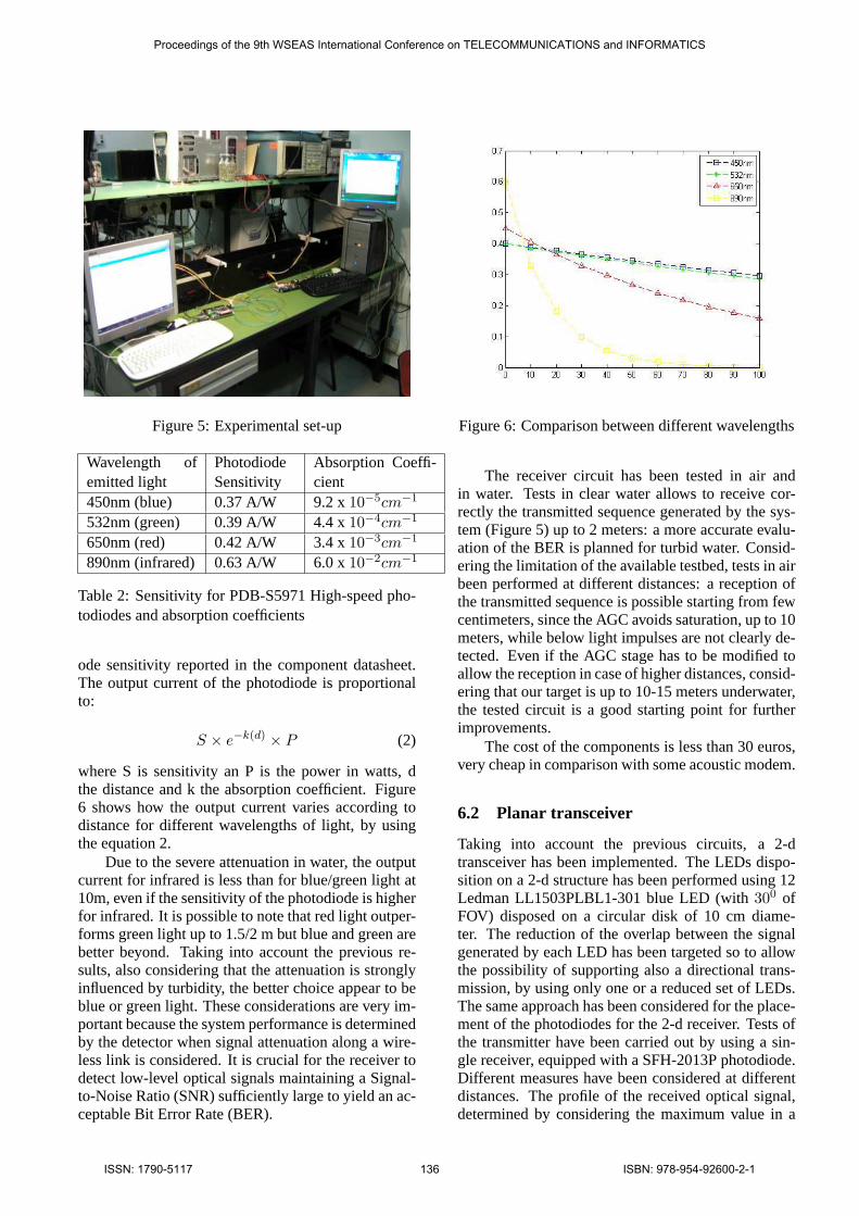
Figure 5: Experimental set-up
Wavelength ofemitted light
PhotodiodeSensitivity
Absorption Coeffi-cient
450nm (blue) 0.37 A/W 9.2 x10⁻⁵cm−1
532nm (green) 0.39 A/W 4.4 x10⁻⁴cm−1
650nm (red) 0.42 A/W 3.4 x10⁻³cm−1
890nm (infrared) 0.63 A/W 6.0 x10⁻²cm−1
Table 2: Sensitivity for PDB-S5971 High-speed pho-todiodes and absorption coefficients
ode sensitivity reported in the component datasheet.The output current of the photodiode is proportionalto:
S × e−k(d) × P (2)
where S is sensitivity an P is the power in watts, dthe distance and k the absorption coefficient. Figure6 shows how the output current varies according todistance for different wavelengths of light, by usingthe equation 2.
Due to the severe attenuation in water, the outputcurrent for infrared is less than for blue/green light at10m, even if the sensitivity of the photodiode is higherfor infrared. It is possible to note that red light outper-forms green light up to 1.5/2 m but blue and green arebetter beyond. Taking into account the previous re-sults, also considering that the attenuation is stronglyinfluenced by turbidity, the better choice appear to beblue or green light. These considerations are very im-portant because the system performance is determinedby the detector when signal attenuation along a wire-less link is considered. It is crucial for the receiver todetect low-level optical signals maintaining a Signal-to-Noise Ratio (SNR) sufficiently large to yield an ac-ceptable Bit Error Rate (BER).
Figure 6: Comparison between different wavelengths
The receiver circuit has been tested in air andin water. Tests in clear water allows to receive cor-rectly the transmitted sequence generated by the sys-tem (Figure 5) up to 2 meters: a more accurate evalu-ation of the BER is planned for turbid water. Consid-ering the limitation of the available testbed, tests in airbeen performed at different distances: a reception ofthe transmitted sequence is possible starting from fewcentimeters, since the AGC avoids saturation, up to 10meters, while below light impulses are not clearly de-tected. Even if the AGC stage has to be modified toallow the reception in case of higher distances, consid-ering that our target is up to 10-15 meters underwater,the tested circuit is a good starting point for furtherimprovements.
The cost of the components is less than 30 euros,very cheap in comparison with some acoustic modem.
6.2 Planar transceiver
Taking into account the previous circuits, a 2-dtransceiver has been implemented. The LEDs dispo-sition on a 2-d structure has been performed using 12Ledman LL1503PLBL1-301 blue LED (with300 ofFOV) disposed on a circular disk of 10 cm diame-ter. The reduction of the overlap between the signalgenerated by each LED has been targeted so to allowthe possibility of supporting also a directional trans-mission, by using only one or a reduced set of LEDs.The same approach has been considered for the place-ment of the photodiodes for the 2-d receiver. Tests ofthe transmitter have been carried out by using a sin-gle receiver, equipped with a SFH-2013P photodiode.Different measures have been considered at differentdistances. The profile of the received optical signal,determined by considering the maximum value in a
Proceedings of the 9th WSEAS International Conference on TELECOMMUNICATIONS and INFORMATICS
ISSN: 1790-5117 136 ISBN: 978-954-92600-2-1

Figure 7: Circular transceiver configuration used forexperimental tests (transmitter on the top)
line-of-sight condition and the minimum value whichis measured between a LED and another, show thatthe generated light impulses is uniformly distributedon the surface. Tests on the receiver have shown aperformance decrease in comparison with the point-to-point circuit due to the noise generated by the pho-todiodes which are not directly exposed to the lightimpulses. Nevertheless a reception up to 4 meters inair can be achieved.
7 Conclusion and Future Develop-ment
The here described work is to be considered as a firststep targeting the implementation of an optical mod-ule interfaced with current terrestrial technology forWSN and circuits for optical communication in or-der to build an optical UWSN. The implemented cir-cuits, even if under improvement, are a good start-ing point for an effective high data-rate and low-costunderwater communication. Next developments areaimed to implements new services in the MAC Layerand to perform communication tests with more thantwo nodes starting from a planar optical connection,while currently only point-to-point tests have beenperformed. In addition, the use of a limited numberof LEDs for a directional communication, when thetopology of the network has been fixed, and the pos-sibility of changing the wavelength of the emitter, bychoosing different colors (blue, red or green), if waterturbidity varies, can be interesting to explore.
Acknowledgements: We thanks Mr. Giorgio Carlinifor his support to circuits implementation.
References:
[1] Ian F. Akyildiz and Dario Pompili and Tom-maso Melodia, Underwater acoustic sensor net-works: research challengesUnderwater acousticsensor networks: research challenges, pp. 257-279, 2005.
[2] Baiden, G. and Bissiri, Y., High BandwidthOptical Networking for Underwater UntetheredTeleRobotic Operation,OCEANS 2007, pp. 1-9,2007.
[3] LanboLiu and Shengli Zhou and Jun-Hong Cui,Prospects and problems of wireless communi-cation for underwater sensor networks,WirelessCommunication Mobile Comput., pp. 977–994,2008.
[4] Deepak Dasalukunte, Viktor Owall, A GenericHardware MAC for Wireless Personal Area Net-work Platforms,The 11th International Sympo-sium on Wireless Personal Multimedia Commu-nication (WPMC’08), 2008.
[5] W.L.Pang, K.W. Chew, Florence Choong, E.S.Teoh, VHDL Modeling of the IEEE802.11b DFCMAC, Proceedings of the 6th WSEAS Interna-tional Conference on Instrumentation, Measure-ment, Circuits and Systems, Hangzhou, China,April 15-17, 2007.
[6] http://www.wiselaboratory.it/.[7] Giles, J.W. and Bankman, I.N., Underwater op-
tical communications systems. Part 2: basic de-sign considerations,IEEE Military Communica-tions Conference (MILCOM 2005), pp. 1700-1705, Vol. 3, 2005.
[8] Valadas, R.T. and Tavares, A.R. and Duarte,A.M.deO. and Moreira, A.C. and Lomba, C.T.,The infrared physical layer of the IEEE 802.11standard for wireless local area networksIEEECommunications Magazine, pp. 107-112, 1998.
[9] Sui Meihong and Yu Xinsheng and Zhang FengliThe Evaluation of Modulation Techniques for Un-derwater Wireless Optical CommunicationsInter-national Conference on Communication Softwareand Networks, pp. 138-142, 2009.
[10] Anguita, D. and Brizzolara, D. and Parodi, G.Building an Underwater Wireless Sensor NetworkBased on Optical: Communication: ResearchChallenges and Current ResultsThird Interna-tional Conference on Sensor Technologies andApplications, 2009. SENSORCOMM ’09, pp.476-479, 18-23 June 2009
Proceedings of the 9th WSEAS International Conference on TELECOMMUNICATIONS and INFORMATICS
ISSN: 1790-5117 137 ISBN: 978-954-92600-2-1