PCD2.F2xxx serial interface modules
26
Document 27-649 │ Version ENG02 │ 2018-08-15 Manual PCD2.F2xxx serial interface modules
-
Upload
khangminh22 -
Category
Documents
-
view
6 -
download
0
Transcript of PCD2.F2xxx serial interface modules
Document 27-649 Version ENG02 2018-08-15
Manual
PCD2.F2xxx serial interface modules
Saia-Burgess Controls AG
Manual PCD2.F2xxx serial interface modules Document 27-649 ENG02 2018-08-15 0-1
0
Inhalt
Contents
0 Contents0.1 Document versions ............................................................................................ 0-2
0.2 Brand names and trademarks .......................................................................... 0-2
1 PCD2.F2xxx serial interface modules1.1 I/O-Slot Modules overview ................................................................................ 1-11.1.1 Serial interface modules PCD7.F1xxS ........................................................... 1-11.1.2 Block diagram ................................................................................................. 1-2
1.2 General info on the PCD2.F2xxx ...................................................................... 1-3
1.3 Module description ............................................................................................ 1-41.3.1 Connection terminals ...................................................................................... 1-51.3.2 LEDs ............................................................................................................... 1-51.3.3 Technical data ................................................................................................. 1-61.3.4 Restrictions ..................................................................................................... 1-7
1.4 Module variants ................................................................................................. 1-81.4.1 RS-422/485 on module - PCD2.F2100 port x.0 .............................................. 1-81.4.2 RS-232 on module - PCD2.F2210 Port x.0 (for modem) ................................ 1-101.4.3 Belimo MP-Bus on module - PCD2.F2810 port x.0 ........................................ 1-11
1.5 PCD7.F1xxS serial interface modules for port x.1 ............................................ 1-121.5.1 PCD7.F1xxS modules overview ..................................................................... 1-121.5.2 RS-485/RS-422 - PCD7.F110S serial interface module ................................. 1-131.5.3 RS-232 up to 115 kbit/s, suitable for modem connection
PCD7.F121S serial interface module ............................................................. 1-141.5.4 RS-485 galv. isolation - PCD7.F150S serial interface module ....................... 1-151.5.5 Belimo MP-Bus PCD7.F180S - serial interface module ................................. 1-161.5.6 PCD7.Fxxx - Overview of older interface modules
(no longer available) ....................................................................................... 1-17
2 PCD2 slots are available on...2.1 PCD1.M22xx-C15 ............................................................................................. 2-1
2.2 PCD1.M21xx ..................................................................................................... 2-2
2.3 PCD2.M4xxx ..................................................................................................... 2-3
2.4 PCD2.M5xxx ..................................................................................................... 2-4
0 Contents

Saia-Burgess Controls AG
Manual PCD2.F2xxx serial interface modules Document 27-649 ENG02 2018-08-15 0-2
0
Dokumenthistorie
Contents
0.1 Document versions
Version Date Updated CommentsENG01 2018-02-08 2018-02-08 Translated from the german versionENG02 2018-08-15 - Revised, overview improved, Chapter 2
0.2 Brand names and trademarks
Saia PCD® and Saia PG5® are registered trademarks of Saia-Burgess Controls AG.
Technical changes based on the current technical state of the art
Saia-Burgess Controls AG, 2017. ® All rights reserved.
Published in Switzerland
Saia-Burgess Controls AG
Manual PCD2.F2xxx serial interface modules Document 27-649 ENG02 2018-08-15
Modules overview
PCD2.F2xxx serial interface modules
1-1
1 PCD2.F2xxx serial interface modules
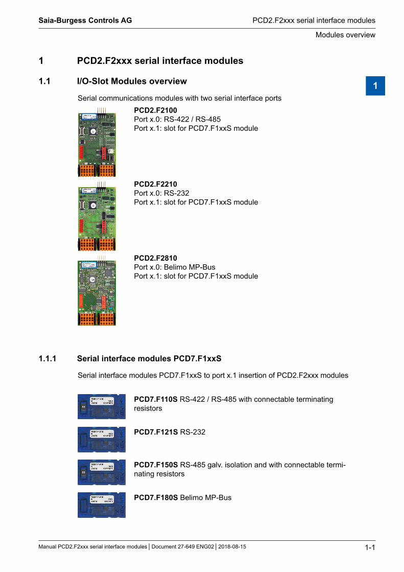
1.1 I/O-Slot Modules overview
Serial communications modules with two serial interface portsPCD2.F2100 Port x.0: RS-422 / RS-485 Port x.1: slot for PCD7.F1xxS module
PCD2.F2210 Port x.0: RS-232 Port x.1: slot for PCD7.F1xxS module
PCD2.F2810 Port x.0: Belimo MP-Bus Port x.1: slot for PCD7.F1xxS module
1.1.1 Serial interface modules PCD7.F1xxS
Serial interface modules PCD7.F1xxS to port x.1 insertion of PCD2.F2xxx modules
PCD7.F110S RS-422 / RS-485 with connectable terminating resistors
PCD7.F121S RS-232
PCD7.F150S RS-485 galv. isolation and with connectable termi-nating resistors
PCD7.F180S Belimo MP-Bus
1
Saia-Burgess Controls AG
Manual PCD2.F2xxx serial interface modules Document 27-649 ENG02 2018-08-15
General info on the PCD2.F2xxx
PCD2.F2xxx serial interface modules
1-2
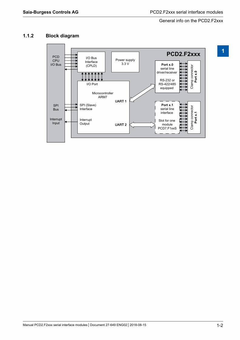
1.1.2 Block diagram
PCD2.F2xxx
UART 1
UART 2
PCDCPU
I/O Bus
SPIBus
InterruptInput
I/O BusInterface(CPLD)
Power supply3.3 V
I/O Port
MicrocontrollerARM7
UART 1SPI (Slave)Interface
InterruptOutput UART 2
Port x.0serial line
driver/receiver
RS-232 orRS-422/485equipped C
lam
p co
nnec
tor
Port
x.0
Port x.1serial lineinterface
Slot for one module
PCD7.F1xxS Cla
mp
conn
ecto
rPo
rt x
.1
1
Saia-Burgess Controls AG
Manual PCD2.F2xxx serial interface modules Document 27-649 ENG02 2018-08-15
PCD2 slots are available on...
PCD2.F2xxx serial interface modules
1-3
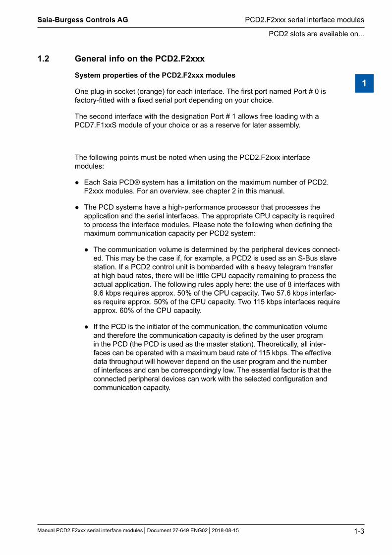
1.2 General info on the PCD2.F2xxx
System properties of the PCD2.F2xxx modules
One plug-in socket (orange) for each interface. The first port named Port # 0 is factory-fitted with a fixed serial port depending on your choice.
The second interface with the designation Port # 1 allows free loading with a PCD7.F1xxS module of your choice or as a reserve for later assembly.
The following points must be noted when using the PCD2.F2xxx interface modules:
Each Saia PCD® system has a limitation on the maximum number of PCD2.F2xxx modules. For an overview, see chapter 2 in this manual.
The PCD systems have a high-performance processor that processes the application and the serial interfaces. The appropriate CPU capacity is required to process the interface modules. Please note the following when defining the maximum communication capacity per PCD2 system:
The communication volume is determined by the peripheral devices connect-ed. This may be the case if, for example, a PCD2 is used as an S-Bus slave station. If a PCD2 control unit is bombarded with a heavy telegram transfer at high baud rates, there will be little CPU capacity remaining to process the actual application. The following rules apply here: the use of 8 interfaces with 9.6 kbps requires approx. 50% of the CPU capacity. Two 57.6 kbps interfac-es require approx. 50% of the CPU capacity. Two 115 kbps interfaces require approx. 60% of the CPU capacity.
If the PCD is the initiator of the communication, the communication volume and therefore the communication capacity is defined by the user program in the PCD (the PCD is used as the master station). Theoretically, all inter-faces can be operated with a maximum baud rate of 115 kbps. The effective data throughput will however depend on the user program and the number of interfaces and can be correspondingly low. The essential factor is that the connected peripheral devices can work with the selected configuration and communication capacity.
1

Saia-Burgess Controls AG
Manual PCD2.F2xxx serial interface modules Document 27-649 ENG02 2018-08-15
PCD2 slots are available on...
PCD2.F2xxx serial interface modules
1-4
1.3 Module description
The PCD2.F2xxx communications modules are designed for the PCD2.Mxxxx sys-tems. Each module has two serial ports, a fixed interface and a second which can be equipped with one of the PCD7.F1xxS modules if required.
Port x.1 still without PCD7.F1xxS module
Port x.0 fix, depending on the
PCD2.F2xxx module selected
Serial communications modules with two serial interface ports:
PCD2.F2100 Port x.0: RS-422 / RS-485 (equipped) Port x.1: slot for PCD7.F1xxS module
PCD2.F2210 Port x.0: RS-232 (equipped) Port x.1: slot for PCD7.F1xxS module
PCD2.F2810 Port x.0: Belimo MP-Bus (equipped) Port x.1: slot for PCD7.F1xxS module
Example of one of the PCD7.F1xxS modules
Examples with attached PCD2.F_ module on Portx.1:with serie PCD2.FxxS with old serie PCD2.FxxS
1
Saia-Burgess Controls AG
Manual PCD2.F2xxx serial interface modules Document 27-649 ENG02 2018-08-15
PCD2 slots are available on...
PCD2.F2xxx serial interface modules
1-5
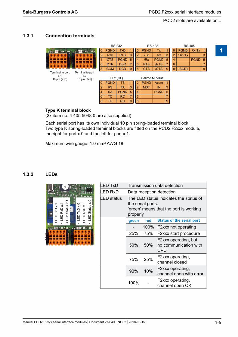
1.3.1 Connection terminals
Terminal to port x.1
10 pin (2x5)
Terminal to port x.0
10 pin (2x5)
RS-232 RS-422 RS-4850 PGND TxD 1 0 PGND Tx 1 0 PGND Rx-Tx 12 RxD RTS 3 2 /Tx Rx 3 2 /Rx-/Tx 34 CTS PGND 5 4 /Rx PGND 5 4 PGND 56 DTR DSR 7 6 RTS /RTS 7 6 78 COM DCD 9 8 CTS /CTS 9 8 (SGD) 9
TTY (CL) Belimo MP-Bus0 PGND TS 1 0 PGND Acom 12 RS TA 3 2 MST IN 34 RA PGND 5 4 PGND 56 TC RC 7 6 78 TG RG 9 8 9
Type K terminal block(2x item no. 4 405 5048 0 are also supplied)
Each serial port has its own individual 10 pin spring-loaded terminal block. Two type K spring-loaded terminal blocks are fitted on the PCD2.F2xxx module, the right for port x.0 and the left for port x.1.
Maximum wire gauge: 1.0 mm2 AWG 18
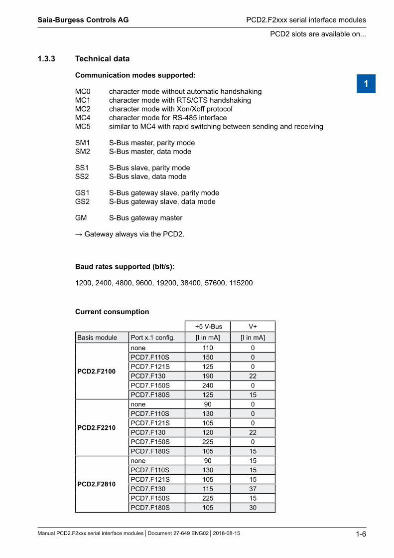
1.3.2 LEDs
< LE
D T
xD x
.1
< LE
D R
xD x
.1
< LE
D S
tatu
s x.
1
< LE
D T
xD x
.0
< LE
D R
xD x
.0
< LE
D S
tatu
s x.
0
LED TxD Transmission data detectionLED RxD Data reception detectionLED status The LED status indicates the status of
the serial ports. ‘green’ means that the port is working properlygreen red Status of the serial port
- 100% F2xxx not operating25% 75% F2xxx start procedure
50% 50%F2xxx operating, but no communication with CPU
75% 25% F2xxx operating, channel closed
90% 10% F2xxx operating, channel open with error
100% - F2xxx operating, channel open OK
1
Saia-Burgess Controls AG
Manual PCD2.F2xxx serial interface modules Document 27-649 ENG02 2018-08-15
PCD2 slots are available on...
PCD2.F2xxx serial interface modules
1-6
1.3.3 Technical data
Communication modes supported:
MC0 character mode without automatic handshaking MC1 character mode with RTS/CTS handshaking MC2 character mode with Xon/Xoff protocol MC4 character mode for RS-485 interface MC5 similar to MC4 with rapid switching between sending and receiving
SM1 S-Bus master, parity mode SM2 S-Bus master, data mode
SS1 S-Bus slave, parity mode SS2 S-Bus slave, data mode
GS1 S-Bus gateway slave, parity mode GS2 S-Bus gateway slave, data mode
GM S-Bus gateway master
→ Gateway always via the PCD2.
Baud rates supported (bit/s):
1200, 2400, 4800, 9600, 19200, 38400, 57600, 115200
Current consumption
+5 V-Bus V+Basis module Port x.1 config. [I in mA] [I in mA]
PCD2.F2100
none 110 0PCD7.F110S 150 0PCD7.F121S 125 0PCD7.F130 190 22PCD7.F150S 240 0PCD7.F180S 125 15
PCD2.F2210
none 90 0PCD7.F110S 130 0PCD7.F121S 105 0PCD7.F130 120 22PCD7.F150S 225 0PCD7.F180S 105 15
PCD2.F2810
none 90 15PCD7.F110S 130 15PCD7.F121S 105 15PCD7.F130 115 37PCD7.F150S 225 15PCD7.F180S 105 30
1
Saia-Burgess Controls AG
Manual PCD2.F2xxx serial interface modules Document 27-649 ENG02 2018-08-15
Module description
PCD2.F2xxx serial interface modules
1-7
1.3.4 Restrictions
The PCD2.F2xxx modules for the PCD2 systems enable users to create up to 8 additional serial interfaces. Note: every additional interface uses CPU capacity.
The use of these 8 ports depends on the type of communication, the baud rate required and the volume of the data transfer.
Additional important factors are:
Communication on the PCD, i.e. Profi-S-Net, Ether-S-Net, USB Use of the web server Data transfer from the CPU to the memory User program in the PCD
1

Saia-Burgess Controls AG
Manual PCD2.F2xxx serial interface modules Document 27-649 ENG02 2018-08-15
Module description
PCD2.F2xxx serial interface modules
1-8
1.4 Module variants
1.4.1 RS-422/485 on module - PCD2.F2100 port x.0
The PCD2.F2100 module contains two different interface types on port x.0, RS-422 with RTS/CTS and RS-485 (electrically connected). The line terminator is integrated into the module and can be connected to the module via a switch.
Switch for network terminator port x.0 (RS-485)
O
C
RS-422 connection
Port x.0RS-422
10 pin spring-loaded terminal block0 PGND Tx 12 /Tx Rx 34 /Rx PGND 56 RTS /RTS 78 CTS /CTS 9
The line terminator in RS-422 mode occurs at 150 Ω in all cases on the PCD2.F2100 module.
PGND 10TX 11/TX 12RX 13/RX 14PGND 15RTS 16/RTS 17CTS 18/CTS 19
PGNDTX/TXRX/RXSGNDRTS/RTSCTS/CTS
Pin
RS-422 Peripherie-device
Terminal
1
Saia-Burgess Controls AG
Manual PCD2.F2xxx serial interface modules Document 27-649 ENG02 2018-08-15
Module description
PCD2.F2xxx serial interface modules
1-9
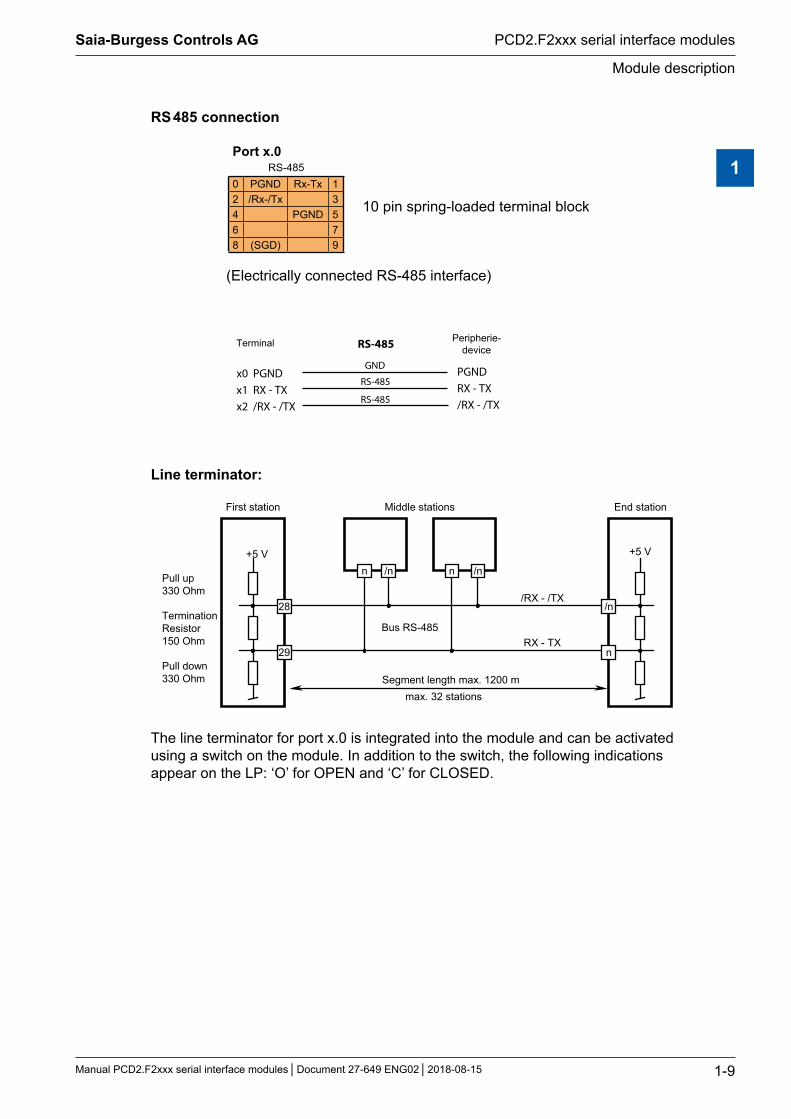
RS 485 connection
Port x.0RS-485
10 pin spring-loaded terminal block0 PGND Rx-Tx 12 /Rx-/Tx 34 PGND 56 78 (SGD) 9
(Electrically connected RS-485 interface)
x0 PGNDx1 RX - TXx2 /RX - /TX
PGNDRX - TX/RX - /TX
GND
RS-485
RS-485
RS-485 Peripherie-device
Terminal
Line terminator:
+5 V
/RX - /TX
n n
29 n
/n
/n/n
28
RX - TX
+5 V
Pull up 330 Ohm
TerminationResistor150 Ohm
Segment length max. 1200 mmax. 32 stations
Bus RS-485
First station Middle stations End station
Pull down 330 Ohm
The line terminator for port x.0 is integrated into the module and can be activated using a switch on the module. In addition to the switch, the following indications appear on the LP: ‘O’ for OPEN and ‘C’ for CLOSED.
1
Saia-Burgess Controls AG
Manual PCD2.F2xxx serial interface modules Document 27-649 ENG02 2018-08-15
Module description
PCD2.F2xxx serial interface modules
1-10
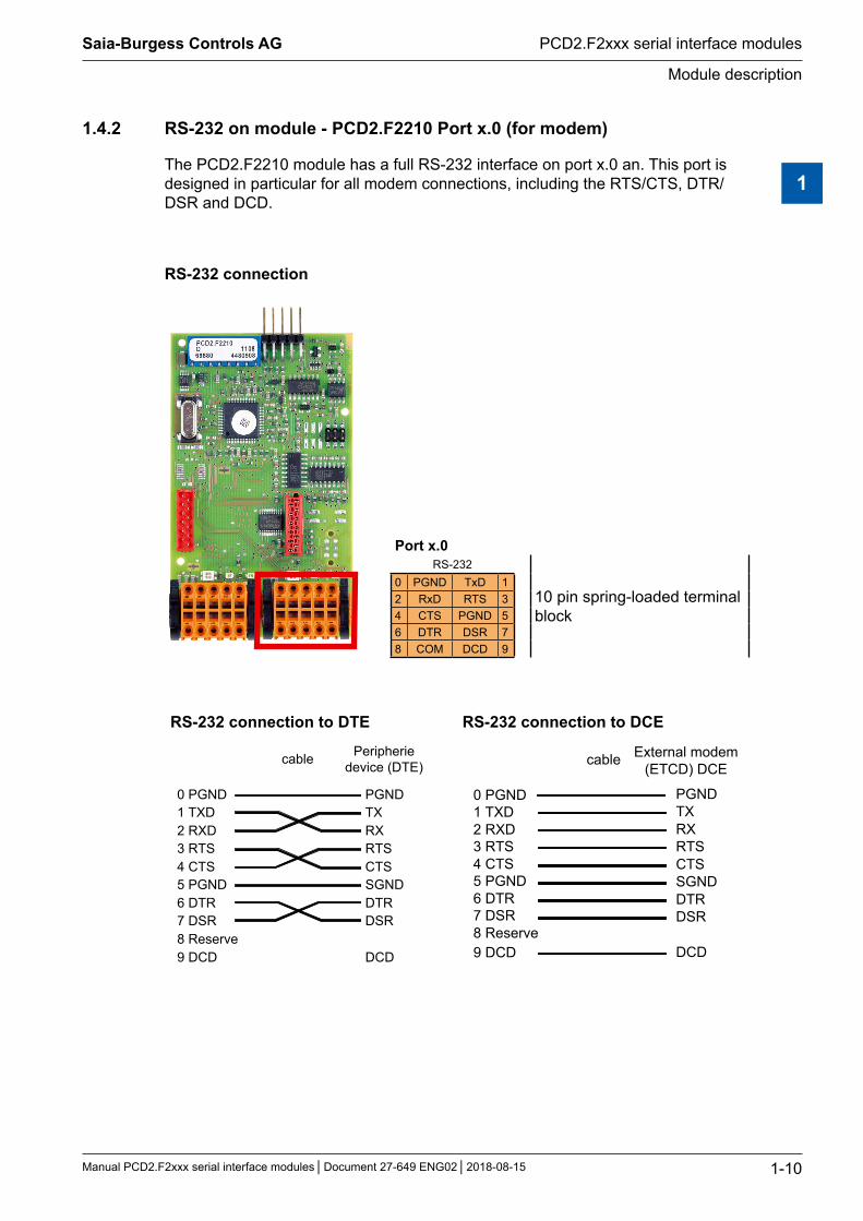
1.4.2 RS-232 on module - PCD2.F2210 Port x.0 (for modem)
The PCD2.F2210 module has a full RS-232 interface on port x.0 an. This port is designed in particular for all modem connections, including the RTS/CTS, DTR/DSR and DCD.
RS-232 connection
Port x.0RS-232
10 pin spring-loaded terminal block
0 PGND TxD 12 RxD RTS 34 CTS PGND 56 DTR DSR 78 COM DCD 9
RS-232 connection to DTE RS-232 connection to DCE
6 DTR
0 PGND1 TXD2 RXD3 RTS4 CTS5 PGND
7 DSR
9 DCD
PGNDTXRXRTSCTSSGNDDTRDSR
DCD
cable Peripheriedevice (DTE)
8 Reserve
PGNDTXRXRTSCTSSGNDDTRDSR
DCD
0 PGND1 TXD2 RXD3 RTS4 CTS5 PGND6 DTR7 DSR
9 DCD8 Reserve
cable External modem(ETCD) DCE
1
Saia-Burgess Controls AG
Manual PCD2.F2xxx serial interface modules Document 27-649 ENG02 2018-08-15
Module variants
PCD2.F2xxx serial interface modules
1-11
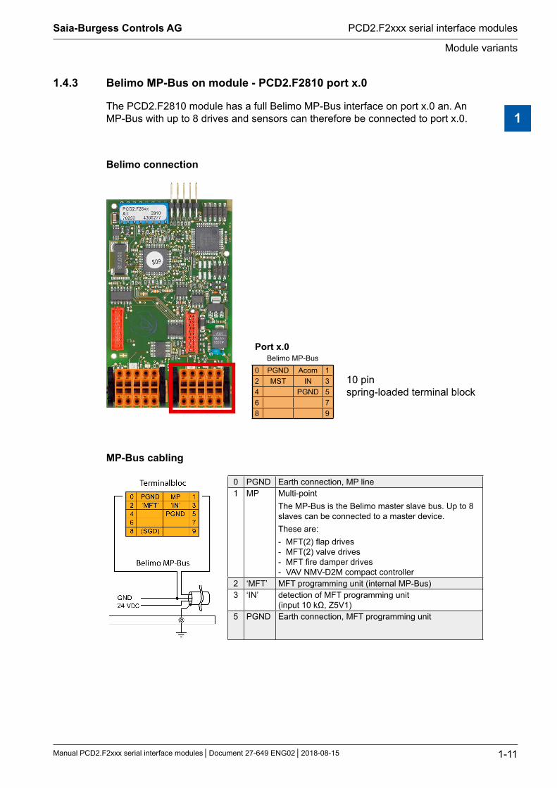
1.4.3 Belimo MP-Bus on module - PCD2.F2810 port x.0
The PCD2.F2810 module has a full Belimo MP-Bus interface on port x.0 an. An MP-Bus with up to 8 drives and sensors can therefore be connected to port x.0.
Belimo connection
Port x.0Belimo MP-Bus
10 pin spring-loaded terminal block
0 PGND Acom 12 MST IN 34 PGND 56 78 9
MP-Bus cabling
0 PGND Earth connection, MP line 1 MP Multi-point
The MP-Bus is the Belimo master slave bus. Up to 8 slaves can be connected to a master device. These are: - MFT(2) flap drives - MFT(2) valve drives - MFT fire damper drives - VAV NMV-D2M compact controller
2 ‘MFT’ MFT programming unit (internal MP-Bus) 3 ‘IN’ detection of MFT programming unit
(input 10 kΩ, Z5V1) 5 PGND Earth connection, MFT programming unit
1
Saia-Burgess Controls AG
Manual PCD2.F2xxx serial interface modules Document 27-649 ENG02 2018-08-15
Module variants
PCD2.F2xxx serial interface modules
1-12
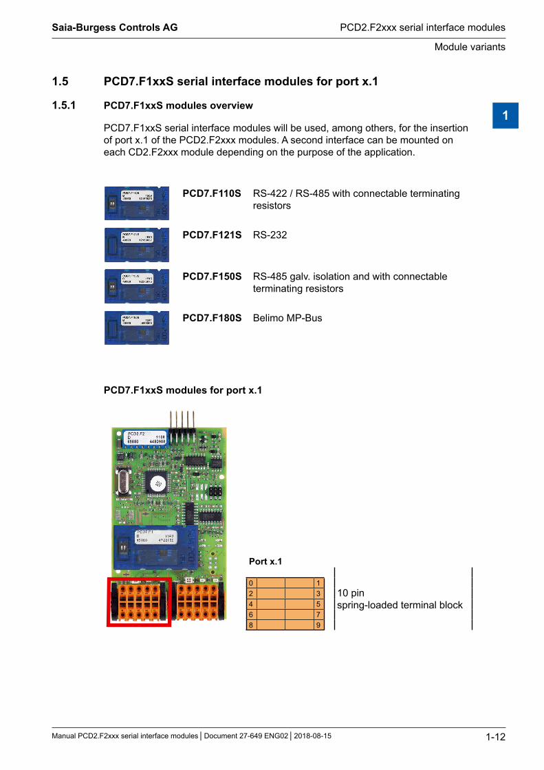
1.5 PCD7.F1xxS serial interface modules for port x.1
1.5.1 PCD7.F1xxS modules overview
PCD7.F1xxS serial interface modules will be used, among others, for the insertion of port x.1 of the PCD2.F2xxx modules. A second interface can be mounted on each CD2.F2xxx module depending on the purpose of the application.
PCD7.F110S RS-422 / RS-485 with connectable terminating resistors
PCD7.F121S RS-232
PCD7.F150S RS-485 galv. isolation and with connectable terminating resistors
PCD7.F180S Belimo MP-Bus
PCD7.F1xxS modules for port x.1
Port x.1
10 pin spring-loaded terminal block
0 12 34 56 78 9
1

Saia-Burgess Controls AG
Manual PCD2.F2xxx serial interface modules Document 27-649 ENG02 2018-08-15
Module variants
PCD2.F2xxx serial interface modules
1-13
1.5.2 RS-485/RS-422 - PCD7.F110S serial interface module
The terminating connectors can be linked using slide switches (CLOSED) or isolated (OPEN).
PCD7.F110S RS-485 terminatorSlider
21C
O
Open not terminated (factory setting)
Slider
21C
O
Closed terminated
RS-422 connection
Port x.1RS-422
10 pin spring-loaded terminal block0 PGND Tx 12 /Tx Rx 34 /Rx PGND 56 RTS /RTS 78 CTS /CTS 9
The line terminator in RS-422 mode occurs at 150 Ω in all cases on the PCD2.F2100 module.
PGND 10TX 11/TX 12RX 13/RX 14PGND 15RTS 16/RTS 17CTS 18/CTS 19
PGNDTX/TXRX/RXSGNDRTS/RTSCTS/CTS
Pin
RS-422 Peripherie-device
Terminal
RS 485 connection
Port x.1RS-485
10 pin spring-loaded terminal block0 PGND Rx-Tx 12 /Rx-/Tx 34 PGND 56 78 (SGD) 9
(Electrically connected RS-485 interface)
1
Saia-Burgess Controls AG
Manual PCD2.F2xxx serial interface modules Document 27-649 ENG02 2018-08-15
Module variants
PCD2.F2xxx serial interface modules
1-14
x0 PGNDx1 RX - TXx2 /RX - /TX
PGNDRX - TX/RX - /TX
GND
RS-485
RS-485
RS-485 Peripherie-device
Terminal
More details are available in the manual 26-740 “Installation components for RS-485 networks”.
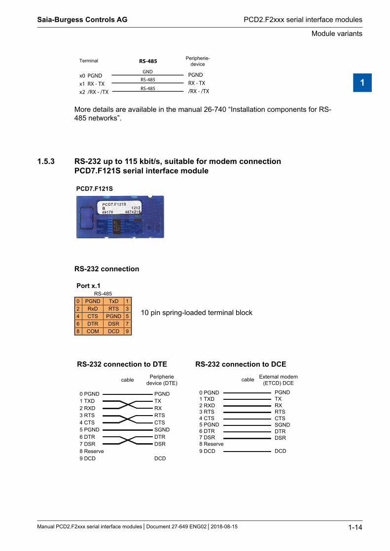
1.5.3 RS-232 up to 115 kbit/s, suitable for modem connection PCD7.F121S serial interface module
PCD7.F121S
RS-232 connection
Port x.1RS-485
10 pin spring-loaded terminal block0 PGND TxD 12 RxD RTS 34 CTS PGND 56 DTR DSR 78 COM DCD 9
RS-232 connection to DTE RS-232 connection to DCE
6 DTR
0 PGND1 TXD2 RXD3 RTS4 CTS5 PGND
7 DSR
9 DCD
PGNDTXRXRTSCTSSGNDDTRDSR
DCD
cable Peripheriedevice (DTE)
8 Reserve
PGNDTXRXRTSCTSSGNDDTRDSR
DCD
0 PGND1 TXD2 RXD3 RTS4 CTS5 PGND6 DTR7 DSR
9 DCD8 Reserve
cable External modem(ETCD) DCE
1
Saia-Burgess Controls AG
Manual PCD2.F2xxx serial interface modules Document 27-649 ENG02 2018-08-15
Module variants
PCD2.F2xxx serial interface modules
1-15
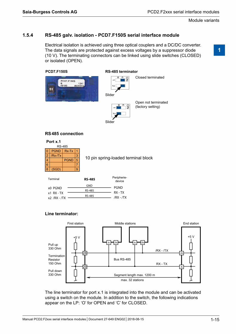
1.5.4 RS-485 galv. isolation - PCD7.F150S serial interface module
Electrical isolation is achieved using three optical couplers and a DC/DC converter. The data signals are protected against excess voltages by a suppressor diode (10 V). The terminating connectors can be linked using slide switches (CLOSED) or isolated (OPEN).
PCD7.F150S RS-485 terminator
Slider
1 2
ON
CO Closed terminated
Slider 1 2
ON
CO Open not terminated (factory setting)
RS 485 connection
Port x.1RS-485
10 pin spring-loaded terminal block0 PGND Rx-Tx 12 /Rx-/Tx 34 PGND 56 78 (SGD) 9
x0 PGNDx1 RX - TXx2 /RX - /TX
PGNDRX - TX/RX - /TX
GND
RS-485
RS-485
RS-485 Peripherie-device
Terminal
Line terminator:
+5 V
/RX - /TX
n n
29 n
/n
/n/n
28
RX - TX
+5 V
Pull up 330 Ohm
TerminationResistor150 Ohm
Segment length max. 1200 mmax. 32 stations
Bus RS-485
First station Middle stations End station
Pull down 330 Ohm
The line terminator for port x.1 is integrated into the module and can be activated using a switch on the module. In addition to the switch, the following indications appear on the LP: ‘O’ for OPEN and ‘C’ for CLOSED.
1
Saia-Burgess Controls AG
Manual PCD2.F2xxx serial interface modules Document 27-649 ENG02 2018-08-15
Module variants
PCD2.F2xxx serial interface modules
1-16
When using this module, the permitted ambient temperature for the control unit is reduced by 5°C.
More details are available in the manual 26-740 “Installation components for RS-485 networks”.
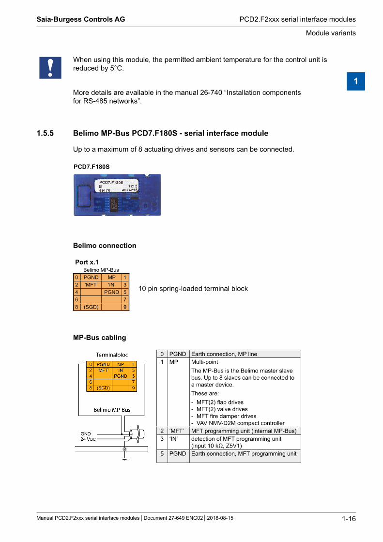
1.5.5 Belimo MP-Bus PCD7.F180S - serial interface module
Up to a maximum of 8 actuating drives and sensors can be connected.
PCD7.F180S
Belimo connection
Port x.1Belimo MP-Bus
10 pin spring-loaded terminal block0 PGND MP 12 ‘MFT’ ‘IN’ 34 PGND 56 78 (SGD) 9
MP-Bus cabling
0 PGND Earth connection, MP line 1 MP Multi-point
The MP-Bus is the Belimo master slave bus. Up to 8 slaves can be connected to a master device. These are: - MFT(2) flap drives - MFT(2) valve drives - MFT fire damper drives - VAV NMV-D2M compact controller
2 ‘MFT’ MFT programming unit (internal MP-Bus) 3 ‘IN’ detection of MFT programming unit
(input 10 kΩ, Z5V1) 5 PGND Earth connection, MFT programming unit
1
Saia-Burgess Controls AG
Manual PCD2.F2xxx serial interface modules Document 27-649 ENG02 2018-08-15
Module variants
PCD2.F2xxx serial interface modules
1-17
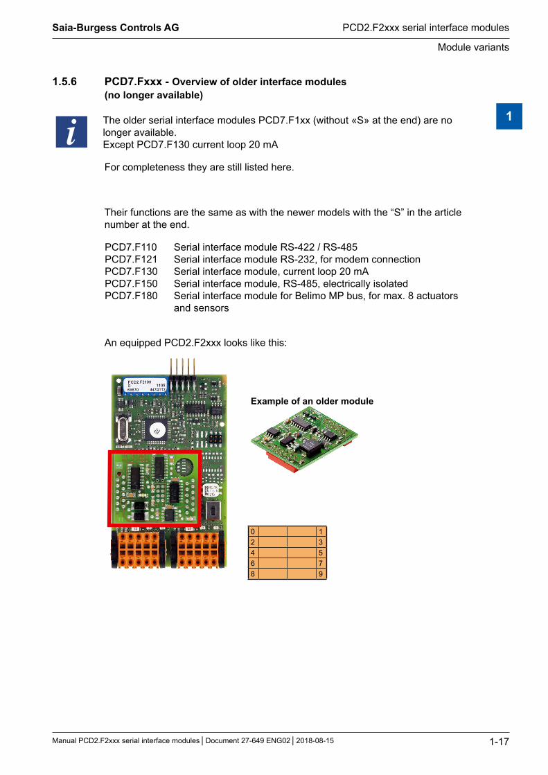
1.5.6 PCD7.Fxxx - Overview of older interface modules (no longer available)
The older serial interface modules PCD7.F1xx (without «S» at the end) are no longer available. Except PCD7.F130 current loop 20 mA
For completeness they are still listed here.
Their functions are the same as with the newer models with the “S” in the article number at the end.
PCD7.F110 Serial interface module RS-422 / RS-485PCD7.F121 Serial interface module RS-232, for modem connectionPCD7.F130 Serial interface module, current loop 20 mAPCD7.F150 Serial interface module, RS-485, electrically isolatedPCD7.F180 Serial interface module for Belimo MP bus, for max. 8 actuators
and sensors
An equipped PCD2.F2xxx looks like this:
Example of an older module
0 12 34 56 78 9
1
PCD2 slots are available on...
2-1
PCD1.M22xx-C15
Saia-Burgess Controls AG
Manual PCD2.F2xxx serial interface modules Document 27-649 ENG02 2018-08-15
2
2 PCD2 slots are available on...
This chapter indicates which PCD controllers can be used with which PCD2.F2xxx modules.
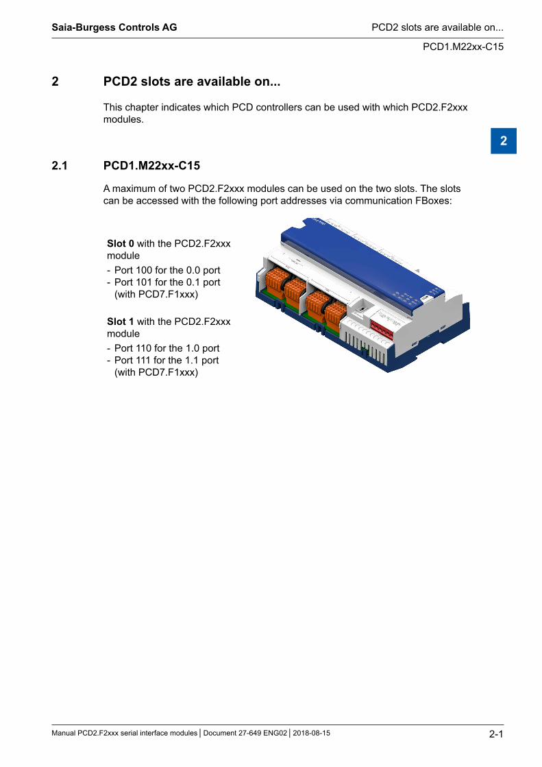
2.1 PCD1.M22xx-C15
A maximum of two PCD2.F2xxx modules can be used on the two slots. The slots can be accessed with the following port addresses via communication FBoxes:
Slot 0 with the PCD2.F2xxx module - Port 100 for the 0.0 port - Port 101 for the 0.1 port (with PCD7.F1xxx)
Slot 1 with the PCD2.F2xxx module - Port 110 for the 1.0 port - Port 111 for the 1.1 port (with PCD7.F1xxx)
PCD2 slots are available on...
2-2
PCD1.M21xx
Saia-Burgess Controls AG
Manual PCD2.F2xxx serial interface modules Document 27-649 ENG02 2018-08-15
2
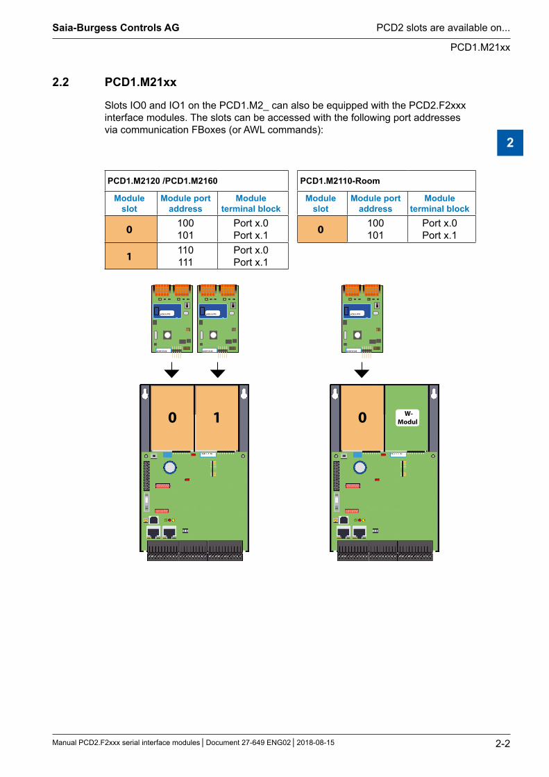
2.2 PCD1.M21xx
Slots IO0 and IO1 on the PCD1.M2_ can also be equipped with the PCD2.F2xxx interface modules. The slots can be accessed with the following port addresses via communication FBoxes (or AWL commands):
PCD1.M2120 /PCD1.M2160 PCD1.M2110-Room
Module slot
Module port address
Module terminal block
Module slot
Module port address
Module terminal block
0 100101
Port x.0Port x.1 0 100
101Port x.0Port x.1
1 110111
Port x.0Port x.1
0 1
PCD2.F2100
PCD7.F1xxS
PCD2.F2100
PCD7.F1xxS
0
PCD2.F2100
PCD7.F1xxS
W-Modul
PCD2 slots are available on...
2-3
PCD2.M4xxx
Saia-Burgess Controls AG
Manual PCD2.F2xxx serial interface modules Document 27-649 ENG02 2018-08-15
2
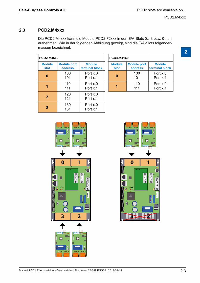
2.3 PCD2.M4xxx
Die PCD2.M4xxx kann die Module PCD2.F2xxx in den E/A-Slots 0…3 bzw. 0 … 1 aufnehmen. Wie in der folgenden Abbildung gezeigt, sind die E/A-Slots folgender-massen bezeichnet:
PCD2.M4560 PCD4.M4160
Module slot
Module port address
Module terminal block
Module slot
Module port address
Module terminal block
0100101
Port x.0Port x.1 0
100101
Port x.0Port x.1
1110111
Port x.0Port x.1 1
110111
Port x.0Port x.1
2120121
Port x.0Port x.1
3130131
Port x.0Port x.1
0 1
3 2
PCD2.F2100
PCD7.F1xxS
PCD2.F2100
PCD7.F1xxS
PCD2.F2100
PCD7.F1xxS
PCD2.F2100
PCD7.F1xxS
0 1
3 2
PCD2.F2100
PCD7.F1xxS
PCD2.F2100
PCD7.F1xxS
PCD2 slots are available on...
2-4
PCD2.M5xxx
Saia-Burgess Controls AG
Manual PCD2.F2xxx serial interface modules Document 27-649 ENG02 2018-08-15
2
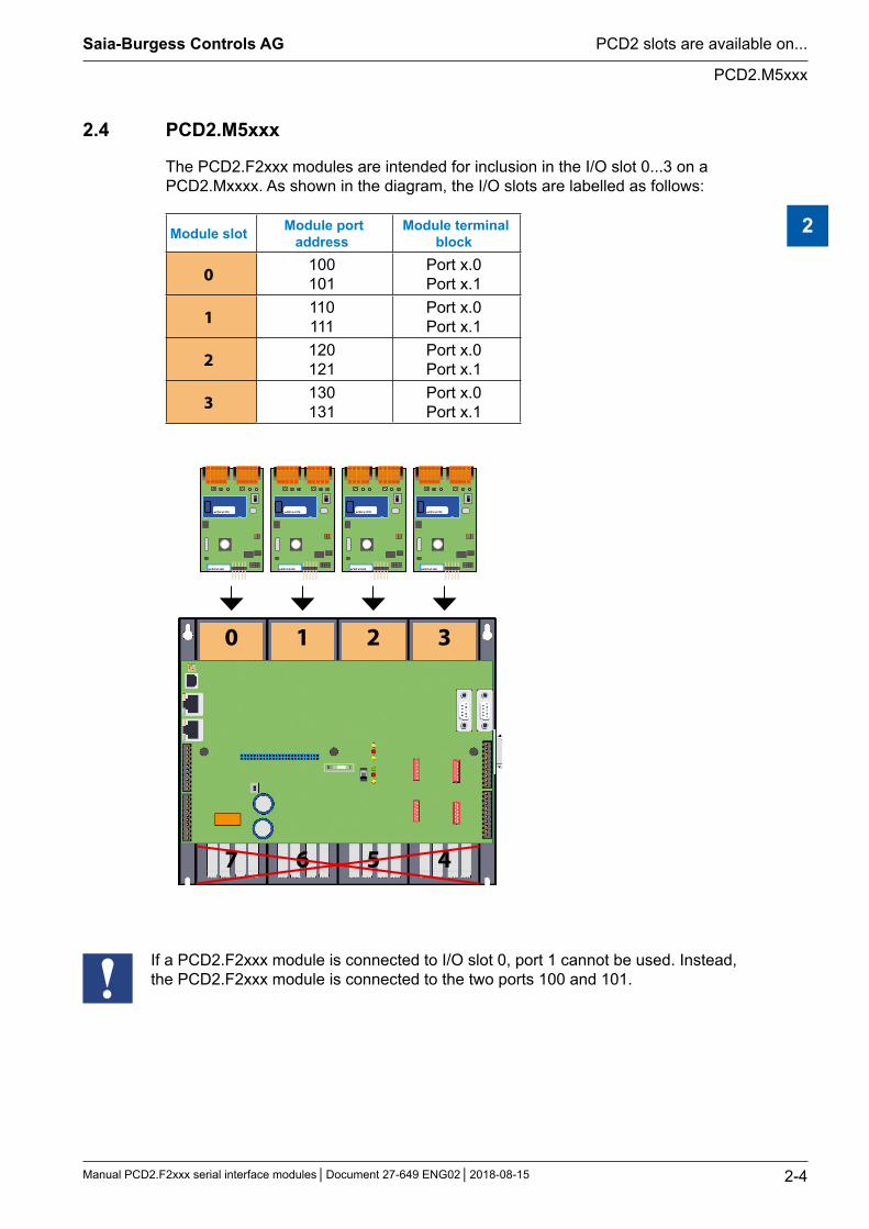
2.4 PCD2.M5xxx
The PCD2.F2xxx modules are intended for inclusion in the I/O slot 0...3 on a PCD2.Mxxxx. As shown in the diagram, the I/O slots are labelled as follows:
Module slot Module port address
Module terminal block
0 100101
Port x.0Port x.1
1 110111
Port x.0Port x.1
2 120121
Port x.0Port x.1
3 130131
Port x.0Port x.1
0 1 2 3
7 6 5 4
PCD2.F2100
PCD7.F1xxS
PCD2.F2100
PCD7.F1xxS
PCD2.F2100
PCD7.F1xxS
PCD2.F2100
PCD7.F1xxS
If a PCD2.F2xxx module is connected to I/O slot 0, port 1 cannot be used. Instead, the PCD2.F2xxx module is connected to the two ports 100 and 101.

A
A-1
Icons
AppendixSaia-Burgess Controls AG
Manual PCD2.F2xxx serial interface modules Document 27-649 ENG02 2018-08-15
A Appendix
A.1 Icons
This symbol indicates that additional information on this topic exists in this manual, a different manual or technical documentation. There are no direct links to these documents.
This symbol indicates instructions that require strict compliance.
A
A-2
Contact details
AppendixSaia-Burgess Controls AG
Manual PCD2.F2xxx serial interface modules Document 27-649 ENG02 2018-08-15
A.2 Contact details
Saia-Burgess Controls AGBahnhofstrasse 183280 Murten, Switzerland
Head office telephone ............ +41 26 580 30 00SBC Support telephone .......... +41 26 580 31 00Fax .......................................... +41 26 580 34 99
Email support: ........................ [email protected] Support website: .................... www.sbc-support.com SBC website: ......................... www.saia-pcd.com
International agencies and SBC subsidiaries: www.saia-pcd.com/contact
Postal address for customers to return products in Switzerland:
Saia-Burgess Controls AGAfter sales serviceBahnhofstrasse 183280 Murten, Switzerland
![Yackety yack [serial] - Internet Archive](https://static.fdokumen.com/doc/165x107/63276564e491bcb36c0b431c/yackety-yack-serial-internet-archive.jpg)


![Yackety yack [serial]](https://static.fdokumen.com/doc/165x107/6328fdedcedd78c2b50e548e/yackety-yack-serial.jpg)