
In situ evaluation of ground heat exchanger performances ...
Upload
khangminh22Category
view
0download
0
1
A PROJECT REPORT
ON
“DESIGN & ANALYSIS OF BEM TYPE HEAT EXCHANGER”
Submitted by
Shaikh Raihan Noor Mohd (18DME48)
Shaikh Shoaib Ayub (18DME49)
Memon Abdul Gani Irfan (18DME25)
Quraishi Md. Rehan Md.Riyaz (18DME35)
In partial fulfillment for the award of the Degree
Of
BACHELOR OF ENGINEERING IN
MECHANICAL ENGINEERING
UNDER THE GUIDANCE
Of
Prof. Rahul Thavai
DEPARTMENT OF MECHANICAL ENGINEERING
ANJUMAN-I-ISLAM
KALSEKAR TECHNICAL CAMPUS NEW PANVEL, NAVI
MUMBAI – 410206
UNIVERSITY OF MUMBAI
ACADEMIC YEAR 2020 -2021
IR@AIKTC-KRRC
ir.aiktclibrary.org
2
CERTIFICATE
This is to certify that the project entitled “DESIGN AND ANALYSIS OF BEM TYPE HEAT
EXCHANGER” being submitted by Project Group 24 is worthy of consideration for the award of the
degree of “Bachelors in Mechanical Engineering” and is a record of original Bonafede carried out under
our guidance and supervision. The results contained in this respect have not been submitted in part or full
to any other university or institute for the award degree certificate.
Shaikh Raihan Noor Mohd (18DME48)
Shaikh Shoaib Ayub (18DME49)
Memon Abdul Gani Irfan (18DME25)
Quraishi Md. Rehan Md. Riyaz (18DME35)
Prof. Rahul Thavai
(Project Guide) (External Examiner)
C. V. Satam
(Industry Guide)
Prof. Zakir Ansari Dr. Abdul Razzak Honnutagi
(HOD Mechanical Dept) (Director AIKTC)
IR@AIKTC-KRRC
ir.aiktclibrary.org
3
DECLARATION
I declare that this project report entitled “DESIGN AND ANALYSIS OF BEM TYPE HEAT
EXCHANGER” represents my ideas in my own words and where others' ideas or words have been
included, I have adequately cited and referenced the original sources. I also declare that I have adhered to
all principles of academic honesty and integrity and have not misrepresented or fabricated or falsified any
data/fact in my submission. I understand that any violation of the above will be cause for disciplinary action
by the Institute and can also evoke penal action from the sources which have thus not been properly cited
or from whom proper permission has not been taken whenneeded.
Shaikh Raihan Noor Mohd (18DME48)
Shaikh Shoaib Ayub (18DME49)
Memon Abdul Gani Irfan (18DME25)
Quraishi Md. Rehan Md. Riyaz (18DME35)
Date:
Place: New Panvel
IR@AIKTC-KRRC
ir.aiktclibrary.org
4
ACKNOWLEDGEMENT
I consider myself lucky to work under guidance of such talented and experienced people who guided me
all through the completion of my dissertation.
I express my deep sense of gratitude to myguideProf. RAHUL THAVAI,Lecturer of Mechanical
Engineering Department, and Mr. C.V.SATAM (Director, Elgin Process Equipment and Design,
Rabale),for his generous assistance, vast knowledge, experience, views& suggestions and for giving me
their gracious support. I owe a lot to them for this invaluable guidance in spite of their busy schedule.
I am grateful to DR. ABDUL RAKKAK HONNUTAGI, Director for his support and co-operation and
for allowing me to pursue my Diploma Programme besides permitting me to use the laboratory
infrastructure of the Institute.
I am thankful to my H.O.D Prof. ZAKIR ANSARIfor his support at various stages.
Last but not the least my thanks also go to other staff members of Mechanical Engineering Department,
Anjuman-I-Islam’s Kalsekar Technical Campus, Panvel, library staff for their assistance useful views
and tips.
I also take this opportunity to thank my Friends for their support and encouragement at every stage of
my life.
Date:
IR@AIKTC-KRRC
ir.aiktclibrary.org
5
ABSTRACT
The oil and gas field deals with various processes such as refining, chemical mixings and blending,
liquefaction, purification, storage of fluids and chemicals under stipulated pressure and temperature requires
boilers, tubes and pipes, heat exchanger pressure vessels, etc. These have been a very important part of
technical and technological systems such as chemical and reactive processes in Oil and gas field. This
project work deals with a detailed DESIGN AND ANALYSIS OF BEM TYPE HEAT EXCHANGER taken
as a problem definition from client Al Hammra – U.A.E. A detailed design of various parts of vessels like
shell, closure, 55 support, flanges, nozzles etc. Design is carried according to rules of ASME code section
VIII; Division I. The ASME is an American Society of Mechanical Engineers that regulates the design and
construction of boilers and pressure vessels. The BPVC is a standard that provides rules for the design,
fabrication and inspection of boilers and pressure vessels. Code provides rules that permit the use of
materials and alternative methods of construction that are not covered by existing BPVC rules. The
analytical design as per client Al Hammra – U.A.E design data and general notes have been analyzed and
validated using Software tools such as PV-elite, Compress or ANSYS, and detailed modelling using Auto-
CAD tool. It also deals with the study of various parts like flanges, support etc. Various methods of
fabrication and testing such as LPT, RT, and Hydro Test are also included.
IR@AIKTC-KRRC
ir.aiktclibrary.org
6
TABLE OF CONTENT
• List of Figures 8
• List of Tables 9
• Abbreviation and Notation 9
1. Introduction 10 - 16
1.1 Introduction of Industry
1.2 Introduction to Heat Exchanger
1.2.1. Classification Of Heat Exchanger
1.2.2 Types of Heat Exchanger
2. Components of Heat Exchanger 17 - 21
2.1 Shell
2.2 Dish End
2.3 Nozzle
2.4 Saddle Support
3. Design Procedure 22 - 86
3.1 Problem Definition
3.2 Object and Scope of Project
3.3 General Design Rules
3.3.1. Material Selection
3.3.2. UG-16 General Design
3.4 Analytical and Software Calculation
3.4.1. Design of Torrispherical Dish End
3.4.2. Design of Shell
3.4.3. Design of Nozzle
3.4.4. Software Calculation of Saddle Support
3.4.5. Software Calculation of Tube Sheet
3.4.6. Software Calculation of Flange
4. Manufacturing 87 - 90
4.1 Roller Machine
4.2 Hydraulic Press
4.3 Gas Tungsten Arc Welding
IR@AIKTC-KRRC
ir.aiktclibrary.org
7
5. Inspection 91 - 95
5.1 Radiography Test
5.1.1. Dye Penetrare Testing
5.2 Hydrostatic Test
6. Result 96 - 97
6.1 Result
6.2 Conclusion
7. Cost Estimation 98 - 99
7.1 Cost Estimation
8. References 100 - 101
8.1 References
8.1.1. Books
8.1.2. Links
IR@AIKTC-KRRC
ir.aiktclibrary.org

8
LIST OF FIGURES
Figure no. Title Page no.
01 Heat Exchanger 13
02 Classification of Heat Exchanger 14
03 Type of Heat Exchanger 15
04 Shell 18
05 Dish End 19
06 Nozzle 20
07 Saddle Support 21
08 Side View 25
09 Front View 25
10 Isometric View 26
11 Sectional Isometric View 26
12 Torrispherical Dish End 32
13 Isometric View of Dish End 33
14 Shell 36
15 Nozzle 38
16 Nozzle 64
17 Saddle Support 67
18 Tube Sheet 76
19 Flange 79
20 Rolling Machine 88
21 Hydraulic Press 89
22 Gas Tungsten Arc Welding Machine 90
23 Radiography Testing 93
24 Dye Penetrate Testing 94
25 Hydro Testing Machine 95
IR@AIKTC-KRRC
ir.aiktclibrary.org

9
LIST OF TABLES
Table No. Title Page no.
01 Design Data 23
02 Bill of Material 24
03 Nozzle Schedule 24
04 Material selection 30
05 Material Selection 31
06 Result 97
07 Cost Estimation 99
ABBREVIATION AND NOTATION
ASME
American Society of Mechanical Engineers
HX
Heat Exchanger
PO
Purchase Order
TIG
Tungsten Inert Gas
MIG
Metal Inert Gas
DP
Dye Penetrant
RT
Radiography Testing
LPT
Liquid Penetrant Testing
HT
Hydro Test
BPVC
Boilers and Pressure Vessel Codes
IR@AIKTC-KRRC
ir.aiktclibrary.org

10
CHAPTER 01
INTRODUCTION
IR@AIKTC-KRRC
ir.aiktclibrary.org
11
1.1 INTRODUCTION OF ELGIN PROCESS EQUIPMENT PVT. LTD, RABALE:
ELGIN PROCESS EQUIPMENT PVT. LTD, RABALE are manufacturer and Supplier of plant/systems
and Equipment’s. C.V. Satam is Mechanical Engineer. He started his career with Indo Berlin Industries who
supplied the major plants to HOC Ltd. around 1970. He subsequently worked for manufacturers like G.R.
Engineering & Lloyds Steel Industries Ltd. He has also worked with well-known consultants like Tata
Consulting Engineering and Simon Carve India Ltd.
Mr. Satam has diversified experience in the equipment industry. He has worked on Chemical,
Petrochemical, Fertilizers, Nuclear Power, Thermal Power, Pharmaceuticals and Polyester Fiber Industry.
He has been involved with marketing and sales, mechanical design, process design, estimation, purchase
planning, production planning, production & quality control plant maintenance and ISO-9000
documentation. He promoted Process Equipment Engineering and Elgin Process Equipment Pvt. Ltd, which
supplies:
1. Air Drying Plants.
2. Liquid Drying Plants.
3. Low Pressure Dehumidifie
4. Liquid Benzene Dryer (with Udhe and UOP for Nirma ltd.)
IR@AIKTC-KRRC
ir.aiktclibrary.org
12
He also designed and engineered India’s and Asia’s first Benzene Vapor Recovery System in 2002, which
won an international award. He supplied off gas dryer to ONGC through Duke- offshore and Burn Std. Co. In
2005 along with IIT and Clique Development Consultant was instrumental in designing equipment for India’s
largest Solar Water Heating System to Mahananda Dairy at Latur Road.
He was felicitated by Thane Belapur Industries Association for his contribution to installing large common
effluent treatment plant of Navi Mumbai.
Mr. Satam has also traveled abroad to receive management training.
MEMBERSHIPS:
1. PPMAI
2. Institution of Engineers
3. Indian Welding Society
Pressure vessels are vessels operating uncle an external or internal pressure exceeding 1.03 Kg/cm7g. Elgin
has manufactured several pressure vessels for respected customers like FMC Corp., UB petroproducts,
Reliance Group, etc for the past 20 years.
We have performed under inspection by reputed international agencies like Bureau Veritas, RINA, TUV,
DNV and almost all national agencies including EIL.
DESIGN/MANUFACTURING CODE
● Elgin products conform to the following codes:
1. ASME Sec VIII Div 1 2.
2. COADAP
3. AD Merkblatter
4. EN 13445
We can provide design verification on software’s like PV Elite, COMPRESS, etc.
IR@AIKTC-KRRC
ir.aiktclibrary.org
13
1.2 INTRODUCTION TO HEAT EXCHANGER:
Fig. 01 Heat Exchanger
Heat Exchangers are devices used to enhance or facilitate the flow of heat. Every living thing is equipped in
some way or another with heat exchangers. They are widely used in space heating, refrigeration, air
conditioning, power plants, chemical plants, petrochemical plants, petroleum refineries, natural gas
processing, and sewage treatment. The design of STHE including thermodynamic and fluid dynamic design,
cost estimation and optimization, represents a complex process containing an integrated whole of design rules
and empirical knowledge of various fields. The design of STHE involves a large number of geometric and
operating variables as a part of the search for heat exchanger geometry that meets the heat duty requirement
and a given set of design constrains. A STHE is the most common type of heat exchanger in oil refineries and
other large chemical processes, and is suited for higher-pressure applications. As its name implies, this type
of heat exchanger consists of a shell (a large vessel) with a bundle of tubes inside it. One fluid runs through
the tubes and the second runs over the tubes (through the shell) to transfer heat between the two fluids. A set
of tubes is called a tube bundle which may be composed by several types of tubes e.g. plain, longitudinally
finned, etc. Shell and tube heat exchanger are extensively throughout the process industry and as such a basic
understanding of their design, construction and performance. Transfer of heat from one fluid to another is an
important operation for most of the chemical industries. The most common application of heat transfer is in
designing of heat transfer equipment for exchanging heat from one fluid to another fluid. Such devices for
efficient transfer of heat are generally called Heat Exchanger.
IR@AIKTC-KRRC
ir.aiktclibrary.org
14
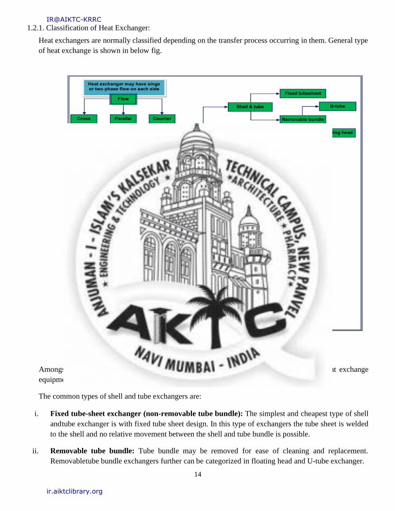
1.2.1. Classification of Heat Exchanger:
Heat exchangers are normally classified depending on the transfer process occurring in them. General type
of heat exchange is shown in below fig.
Fig. 02 Classification of Heat Exchanger
Amongst of all type of exchangers, shell and tube exchangers are most commonly used heat exchange
equipment.
The common types of shell and tube exchangers are:
i. Fixed tube-sheet exchanger (non-removable tube bundle): The simplest and cheapest type of shell
and tube exchanger is with fixed tube sheet design. In this type of exchangers the tube sheet is welded
to the shell and no relative movement between the shell and tube bundle is possible.
ii. Removable tube bundle: Tube bundle may be removed for ease of cleaning and replacement.
Removable tube bundle exchangers further can be categorized in floating head and U-tube exchanger.
IR@AIKTC-KRRC
ir.aiktclibrary.org
15
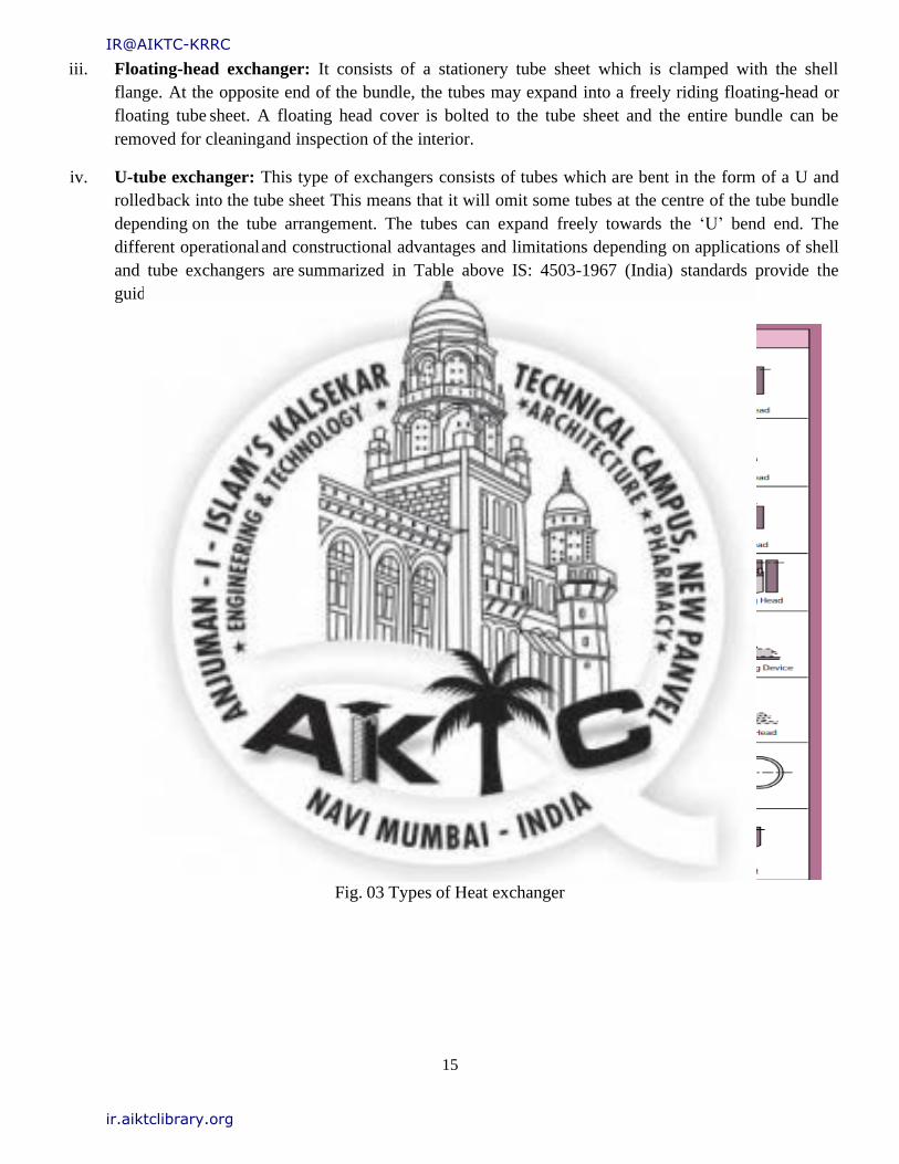
iii. Floating-head exchanger: It consists of a stationery tube sheet which is clamped with the shell
flange. At the opposite end of the bundle, the tubes may expand into a freely riding floating-head or
floating tube sheet. A floating head cover is bolted to the tube sheet and the entire bundle can be
removed for cleaning and inspection of the interior.
iv. U-tube exchanger: This type of exchangers consists of tubes which are bent in the form of a U and
rolled back into the tube sheet This means that it will omit some tubes at the centre of the tube bundle
depending on the tube arrangement. The tubes can expand freely towards the ‘U’ bend end. The
different operational and constructional advantages and limitations depending on applications of shell
and tube exchangers are summarized in Table above IS: 4503-1967 (India) standards provide the
guidelines for the mechanical design of unfired shell and tube heat exchangers.
Fig. 03 Types of Heat exchanger
IR@AIKTC-KRRC
ir.aiktclibrary.org
16
1.2.2. TYPES:
1. BEM, AEM, NEN:
Advantages:
• Provides maximum heat transfer area for a given shell and tube diameter.
• Provides for single and multiple tube passes to assure proper velocity.
• Less costly than removable bundle designs.
Limitation:
• Shell side / outside of the tubes are inaccessible for mechanical cleaning.
• No provision to allow for differential thermal expansion developed between the tube and the
shell side.
• This can be taken care by providing expansion joint on the shell side.
2. AEW, BEW, AEP, BEP, AES, BES:
Advantages:
• Floating tube sheet allows for differential thermal expansion between the shell and the tube
bundle.
• Both the tube bundle and the shell side can be inspected and cleaned mechanically.
Limitation:
• To provide the floating-head cover it is necessary to bolt it to the tube sheet.
• The bolt circle requires the use of space where it would be possible to place a large number of
tubes.
• Tubes cannot expand independently so that huge thermal shock applications should be
avoided.
• Packing materials produce limits on design pressure and temperature.
3. BEU AEU:
Advantages:
• U-tube design allows for differential thermal expansion between the shell and the tube bundle
as well as for individual tubes.
• Both the tube bundle and the shell side can be inspected and cleaned mechanically.
• Less costly than floating head or packed floating head designs
Limitation:
• Because of U-bend some tubes are omitted at the center of the tube bundle.
• Because of U-bend, tubes can be cleaned only by chemical methods.
• Due to U-tube nesting, individual tube is difficult to replace.
• No single tube pass or true counter current flow is possible.
IR@AIKTC-KRRC
ir.aiktclibrary.org

17
CHAPTER 02
COMPONENT
IR@AIKTC-KRRC
ir.aiktclibrary.org
18
2.1 Shell
It is a primary component that contains the pressure. Heat Exchanger shells in the form of different
plates are welded together to form a structure that has a common rotational axis.
The main body of the Heat Exchanger is known as a shell. The process of heat Exchanger generally
occurs in this region. Generally, manhole and handhole is located in this region. No other nozzle is
mainly mounted on it. Internal pressure of the vessel acts more in this region.
Fig. 04 Shell
IR@AIKTC-KRRC
ir.aiktclibrary.org
19
2.2 Dish End
The Heat Exchanger must be closed; so heads are manufactured typically on a curved rather than the
flat. The reason is that curved configuration is stronger and allows heads to thinner, lighter and less
expensive than the flatheads.
The upper and lower part of a Heat Exchanger is known as a dish end. Mostly the inside area of dish
remains empty since no processes of Heat Exchanger occurs. Mostly many of the nozzle is mounted on
the dish end. The manufacturing process of dish end is easy because dish is a single piece and only a
pressing process is to be done.
Fig. 05 Dish End
IR@AIKTC-KRRC
ir.aiktclibrary.org

20
2.3 Nozzle
Nozzle is a cylindrical component that penetrates in the shell or head of a Heat Exchanger. It is the sub
assembles part of pressure vessel which is mounted on a shell & dish as par requirement. Nozzle is
used to transfer/receive working medium from the Heat Exchanger and mounted equipment like
pressure indicator etc.
Fig. 06 Nozzle
IR@AIKTC-KRRC
ir.aiktclibrary.org
21
2.4 Saddle Support
Saddle supports are commonly used to support Horizontal Heat Exchanger. A Heat Exchanger are
subjected to pressure loading i.e. internal or external operating pressure different from ambient
pressure. The Heat Exchanger are of horizontal or vertical type. For horizontal Heat Exchanger the
saddle supporting system plays an important role in the performance of the equipment. A proper saddle
supporting system improves safety and facilitate to operate the Heat Exchanger at higher pressure
conditions which finally leads to higher efficiency.
Fig. 07 Saddle Support
IR@AIKTC-KRRC
ir.aiktclibrary.org
22
CHAPTER 03
DESIGN PROCEDURE
IR@AIKTC-KRRC
ir.aiktclibrary.org
23
3.1 Problem Definition
To design and analyse the Heat Exchanger BEM as per ASME & TEMA guidelines for the client
specification. Design data by client:
1. Design pressure (Atmospheric) P = 9.80665 bar, P = 10 kg/cm2
2. Design temperature: - T = 140o
3. Design code: - ASME & TEMA, Hx position = Horizontal
4. Shell type: - Cylindrical Shell
5. Head: -Tori spherical
6. Outside diameter: - 470mm
7. Length of Shell: - 3609.06mm
8. Material of Shell: - SA-516 GR.70
9. Nozzle:- 7, Flange material: - SA-516 GR.70
Table 01. Design Data
MARK QTY DENOMINATION DN(1) TYPE
I 1 OUTLET 3’’ FLANGE
II 2 VISUAL LEVEL 1’’ FLANGE
III 1 SULPHURIC ACID LOAD 3’’ FLANGE
IV 1 MAN HOLE 24’’ FLANGE
V 1 LEVEL TRANSMITTER 3’’ FLANGE
VI 1 VENT 4’’ FLANGE
VII 1 PRESSURE SAFETY VALVE
DISCHARGE 3’’ FLANGE
VIII 1 OVERFLOW 3’’ FLANGE
IX 1 DRAIN 3’’ FLANGE
IR@AIKTC-KRRC
ir.aiktclibrary.org

24
Table 02. Bill of Material
SR NO. NOZZLE NOZZLE
DIA NOZZLE
SCHEDULE
1 N1 4’’ 80
2 N2 3’’ 160
3 N3 3’’ 160
4 N4 3’’ 160
5 N5 3’’ 160
6 N6 3’’ 160
7 N7 4’’ 80
7 MANHOLE /HANDHOLE 24’’ 160
Table 03. Nozzle Schedule
P. NO. PARTICULARS QTY MATERIAL SIZE
1 SHELL 3 SA 516 GR.70
(LTCS)
479OD X 635LG X
8THK
2 DISH END 2 SA 516 GR.70
(LTCS)
10THK (NOM) X
8THK (MIN)
3 SADDLE PL 2 IS 2062 450X 10THK X 200
4 BASE PL 2 IS2062 450 X 200 X 10THK
5 EARTHING BOSS 4 SS 304 25d X 25LG
6 NAME PLATE
BKT 2 SS 304 232 X 125 X 3THK
7 NAME PLATE 1 SS 304 150 X 110 X 2THK
8
PIPE FOR
NOZZLE N1,
N7 2 SA 106B
101.6ND X SCH80 X
14.98 THK
9
PIPE FOR
NOZZLE N2, N3,
N4, N5, N6 5 SA 106B
76.2ND X SCH160 X
7.66THK
10 FLANGE 2 SA516 GR.70 698.5NDX 144.526L X
42.926THK
IR@AIKTC-KRRC
ir.aiktclibrary.org
25
Fig. 08 Side View
Fig. 09 Front View
IR@AIKTC-KRRC
ir.aiktclibrary.org
26
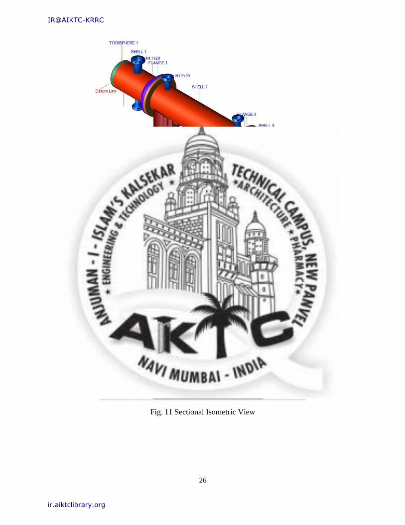
Fig. 10 Isometric View
Fig. 11 Sectional Isometric View
IR@AIKTC-KRRC
ir.aiktclibrary.org
27
3.2 Objective and Scope of Project
i) To understand components of General arrangement Heat Exchanger and its applications.
ii) To design the components of industrial Heat Exchanger vessel by analytical method in reference with
A.S.M.E section viii Div. 1.
iii) To validate the design using software PV-Elite version 2016.
iv) Comparison of analytical and software calculation.
v) Modelling of vessel in PV-Elite software.
IR@AIKTC-KRRC
ir.aiktclibrary.org
28
3.3 General design rules material selection from ASME section VIII Div.1 and Section II
Part D:
3.3.1 Material selection
Selection of materials is important activities that are essential for structural design. The selection of
materials for ASME industrial storage vessels must be code approved. A metallurgical engineer usually
specified the most economical materials at the lowest cost and/or lowest maintenance cost that will be
satisfactory under operating conditions.
There are many factors supported by experience and laboratory test results that must be considered in
selecting the most suitable materials. They include the following:
● Corrosion Resistance
● Strength Requirements
● Cost
● Availability
● Ease of Fabrication
● Cost of Future Maintenance
● Equipment Flexibility.
The range of materials used for industrial storage vessels is wide and includes but is not limited to, the
following:
• Carbon steel (with less than 0.25%carbon).
• Carbon manganese steel (giving higher strength than carbon steel).
• Low alloy steels.
• High alloy steels.
• Austenitic stainless steels.
• Non-ferrous materials (aluminum, copper, nickel and alloys).
• High duty bolting materials.
IR@AIKTC-KRRC
ir.aiktclibrary.org
29
3.3.2 UG-16 General Design (Reference ASME Section VIII Div.1 page no.13):
(a) Thedesignofpressurevesselsandvesselpartsshallconformtothegeneraldesignrequirements in the
following paragraphs and in addition to the specific requirements for Design given in the applicable
Parts of Subsections B and C.
(b) Minimum Thickness of Pressure Retaining Components. Except for the special provisions listed
below, the minimum thickness permitted for shells and heads, after forming and regardless of product
form and material, shall be 1/16 in. (1.5 mm) exclusive of any corrosion allowance. Exceptions are:
(1) The minimum thickness does not apply to heat transfer plates of plate type heat exchangers;
(2) This minimum thickness does not apply to the inner pipe of double pipe heat exchangers nor to
pipes and tubes that are enclosed and protected from mechanical damage by a shell, casing, or
ducting, where such pipes or tubes are NPS 6 (DN 150) and less. This exemption applies whether
or not the outer pipe, shell, or protective element is constructed to Code rules. When the outer
protective element is not provided by the Manufacturer as part of the vessel, the Manufacturer
shall note this on the Manufacturer’s Data Report, and the owner or his designated agent shall
be responsible to assure that the required enclosures are installed prior to operation. Where Pipes
and tubes are fully enclosed; consideration shall be given to avoiding build-up of pressure within
the protective chamber due to a tube/pipe leak.
(3) The minimum thickness of shells and heads of unfired steam boilers shall be 1/4 in. (6 mm)
exclusive of any corrosion allowance;
(4) The minimum thickness of shells and heads used in compressed air service, steam service, and
water service, made from materials listed in Table UCS-23, shall be 3/32 in. (2.5 mm) exclusive
of any corrosion allowance.
(5) This minimum thickness does not apply to the tubes in air cooled and cooling tower heat
exchangers if all the following provisions are met:
a) The design thickness so that the thickness of the material furnished is not more than the smaller
of 0.01 in. (0.25mm).
b) Pipe Under tolerance .If pipe or tube is ordered by its nominal wall thickness, the
manufacturing under tolerance on wall thickness shall be taken into account except for
nozzle wall reinforcement are a requirements.
IR@AIKTC-KRRC
ir.aiktclibrary.org

30
c) After the minimum wall thickness is determined, it shall be increased by an amount
sufficient to provide the manufacturing under tolerance allowed in the pipe or tube
specification.
d) Corrosion Allowance in Design Formulas. The dimensional symbols used in all design
formulas throughout this Division represent dimensions in the corroded condition.
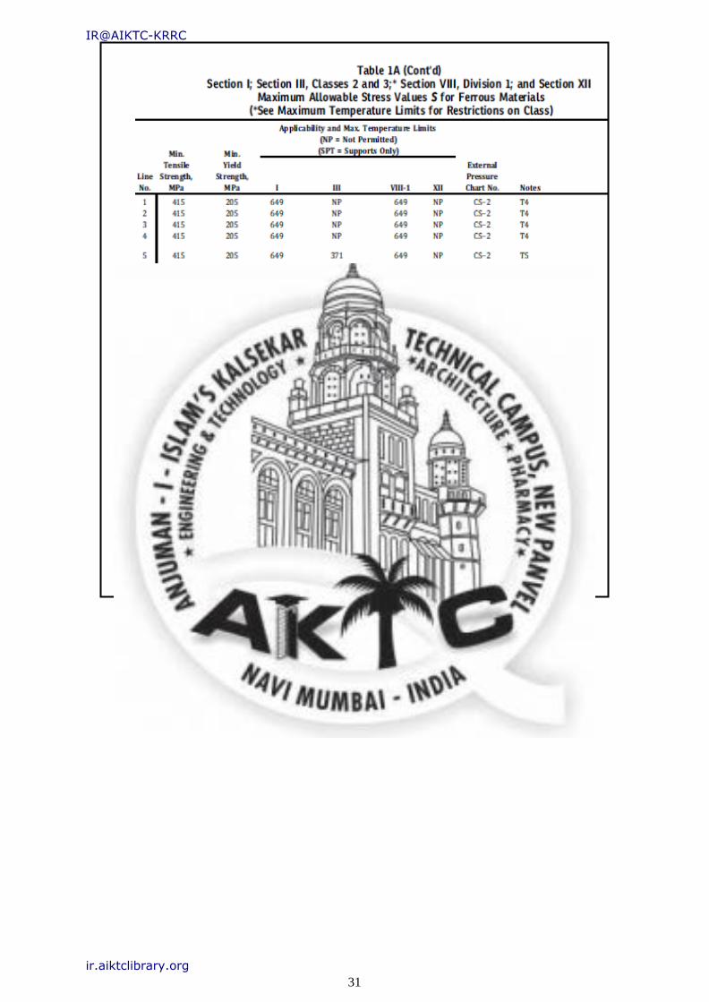
Table 04. Material selection
IR@AIKTC-KRRC
ir.aiktclibrary.org
31
Table 05. Material Selection
IR@AIKTC-KRRC
ir.aiktclibrary.org
32
3.4 Analytical and Software calculation
3.4.1 Design of Torrispherical Dish End:
Fig. 12 Torrispherical dish end
Thickness (t)
t=PLM/2SE-0.2P
Where
M=
¼(3+√(L/r))
L=D=
679mm
r= Knuckle radius =6% of Dia= 6% X 679 =
40.74mm L/r= 679/40.74 = 16.66
M= ¼(3+√16.66) = 1.77
t= (10*679*1.77)/((2*1406.139*1)-(0.2*10))
t=4.28mm
t= 4.28+CA = 4.28+3 = 7.28mm
t= 8mm
t= 8+TA = 8+2 = 10mm
IR@AIKTC-KRRC
ir.aiktclibrary.org

33
MAWP for Dish end
P=2SEt/ML+0.2t
P= (2*1406.139**4)/(1.77*67.9+0.2*1)
P= 23.03 kg/cm2
THEREFORE
MAWP > P
DESIGN IS SAFE
Software calculations for Torispherical dish end
Fig. 13 Isometric View of Dish End
Inside Corroded Head Depth [h]:
M factor for Torispherical Heads (Corroded):
IR@AIKTC-KRRC
ir.aiktclibrary.org

34
Required Thickness due to Internal Pressure [tr]:
Max Allowable Working Pressure at given Thickness, corroded [MAWP]:
M factor for Torispherical Heads (New& Cold):
Maximum Allowable Pressure, New and Cold [MAPNC]:
Actual stress at given pressure and thickness, corroded [Sact]:
Straight Flange Required Thickness:
Straight Flange Maximum Allowable Working Pressure:
IR@AIKTC-KRRC
ir.aiktclibrary.org

35
MDMT Calculations in the Knuckle Portion:
Govrn. thk, tg = 0.787 , tr = 0.188 , c = 0.1250
F in. , E* = 1.00StressRatio=tr*(E*)/(tg -
c)=0.284,Temp.Reduction=140
MDMT Calculations in the Head Straight Flange:
Govrn. thk, tg = 0.866, tr = 0.102 , c = 0.1250
F in. , E* = 1.00StressRatio=tr*(E*)/(tg -
c)=0.137,Temp.Reduction=140
IR@AIKTC-KRRC
ir.aiktclibrary.org
36
3.4.2 Design of Shell
Fig. 14 Shell
THICKNESS (t)
t = PR/SE – 0.6P
t = 10 × 339.5 /1406.139 × 1 – 0.6 × 10
t = 2.42
t = 2.42 + CA =2.42 + 3.179
t = 5.59
t = 6 mm
MAWP CALCULATION:
P = SEt/R+0.6t
P = 1406.139 × 1 × 0.6 / 33.95 + 0.6×0.6
P = 24.59 kg/cm²
MAWP = 24.59 > P = 10 kg/cm²
Hence DESIGN IS SAFE
IR@AIKTC-KRRC
ir.aiktclibrary.org

37
Software calculation for shell
Required Thickness due to Internal Pressure [tr]:
Max. Allowable Working Pressure at given Thickness, corroded[MAWP]:
Maximum Allowable Pressure, New and Cold [MAPNC]:
Actual stress at given pressure and thickness, corroded[Sact]:
Minimum Design Metal Temperature Results:
Govrn. thk, tg = 0.787 , tr = 0.102 , c = 0.1250 in. ,
F E* = 1.00StressRatio=tr*(E*)/(tg -
c)=0.153,Temp.Reduction=140
Cylindrical Shell From 40 To 50 SA-51670,UCS-66 Cr v .Bat F 28
IR@AIKTC-KRRC
ir.aiktclibrary.org

38
3.4.3 Design of Nozzle
Analytical calculation for nozzle 4”
Fig. 15 Nozzle
From ASME SECTION II PART D
S=1026.48kg/cm2
NOZZLE WALL
THICKNESS
OD=4’’=114.3mm
Ro= 57.15mm
NOZZLE WALL THICKNESS
REQUIRED t=(PXRo)/SE-0.6P
t=(142.4X57.15)/1026.48X1-0.6X142.4
t= 8.64mm ...................... (a)
WALL THICKNESS REQUIRED AS PER UG16b
t=5.27mm .................. (b)
SHELL THICKNESS
t=8mm .................... (c)
IR@AIKTC-KRRC
ir.aiktclibrary.org
39
Selecting Greater Value From b
& c t1=8mm
Selecting Minimum Value From a
& b t2=5.27mm
As per UG 45 selecting
8mm From nozzle pipe
schedule chart Taking final
thickness t=8.56mm
Analytical calculation for nozzle 3’’
From ASME SECTION II PART D
S=1026.48kg/cm2
NOZZLE WALL
THICKNESS OD=3’’
=88mm
Ro= 44mm
NOZZLE WALL THICKNESS
REQUIRED t=(PXRo)/SE-0.6P
t=(142.4X44)/1026.48X1-0.6X142.4
t= 6.6mm ...................... (a)
WALL THICKNESS REQUIRED AS PER UG16b
t=4.8mm .................. (b)
SHELL THICKNESS
t=8mm .................... (c)
IR@AIKTC-KRRC
ir.aiktclibrary.org

40
Selecting greater value b & c
t1=8mm
Selecting minimum value from a
& b t2=4.80mm
As per UG 45 selecting 8mm
From nozzle pipe schedule
chart Taking final thickness
t=11.13mm
IR@AIKTC-KRRC
ir.aiktclibrary.org

41
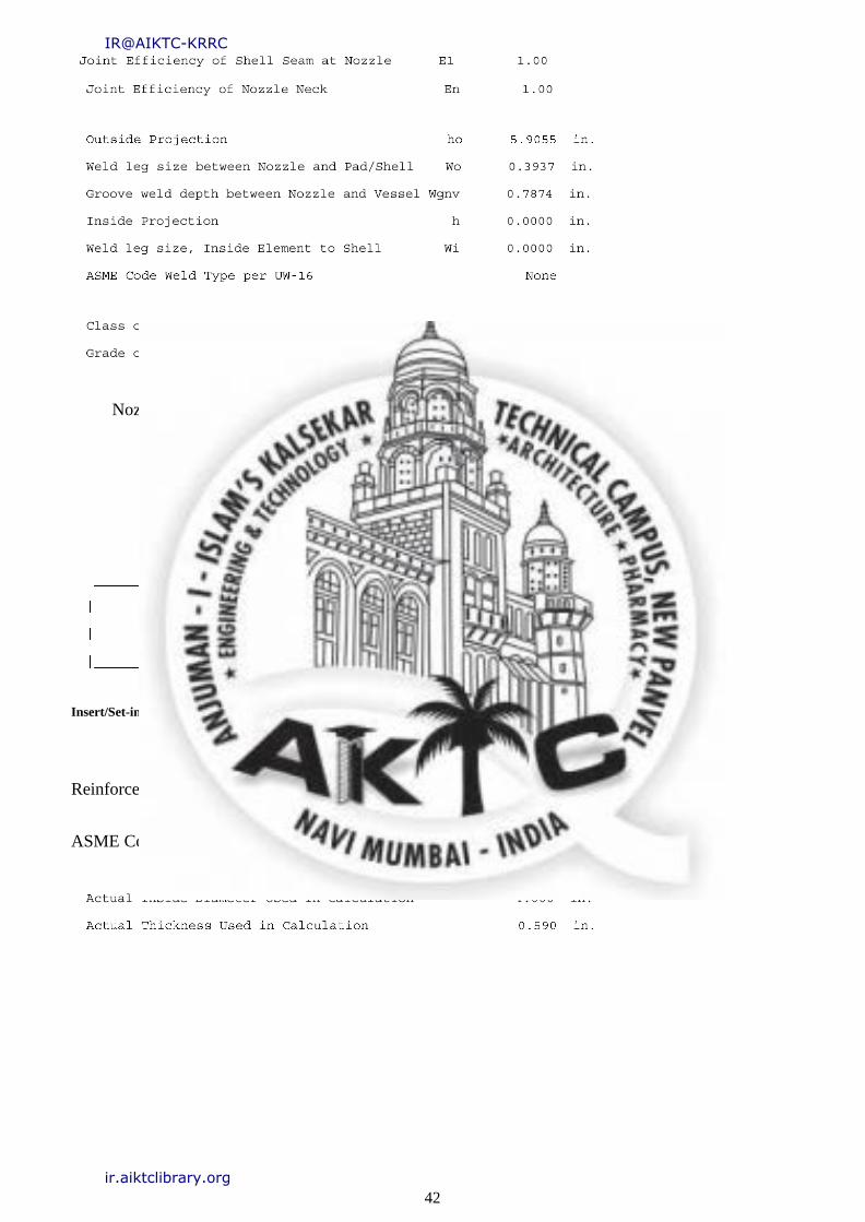
Software calculation for nozzle
INPUT VALUES Nozzle Description: Noz N1Fr20 From:20
Type of Element Connected to the Shell : Nozzle
IR@AIKTC-KRRC
ir.aiktclibrary.org
42
Nozzle Sketch (may not represent actual weld type/configuration)
Insert/Set-in Nozzle No Pad, no Inside projection
Reinforcement CALCULATION, Description: NozN1Fr20
ASME Code, Section VIII,Div.1, 2015,UG-37 toUG-45
IR@AIKTC-KRRC
ir.aiktclibrary.org
43
Reqd thk perUG-37(a)of Cylindrical Shell, Tr [Int. Press]
Reqd thk perUG-37(a)of Nozzle Wall, Trn [Int. Press]
UG-45 Minimum Nozzle Neck Thickness Requirement:[Int. Press.]
Determine Nozzle Thickness candidate [tb]:
Minimum Wall Thickness of Nozzle Necks [tUG-45]:
Available Nozzle Neck Thickness = 0.5898in.-->OK
Nozzle Junction Minimum Design Metal Temperature (MDMT)
Calculations:
MDMT of the Nozzle Neck to Flange Weld, Curve: B
Govrn. thk, tg = 0.590 , tr = 0.017 , c = 0.0000 in. ,
F
E* = 1.00StressRatio =tr * (E*)/(tg-
c)=0.028,Temp. Reduction =140
IR@AIKTC-KRRC
ir.aiktclibrary.org

44
Results Per UW-16.1:
Maximum Allowable Pressure for this Nozzle at this Location:
INPUT VALUES, Nozzle Description: Noz N2Fr20 From:20
Type of Element Connected to the Shell :Nozzle
IR@AIKTC-KRRC
ir.aiktclibrary.org

45
The Pressure Design option was Design Pressure+ static head.
Nozzle Sketch (may not represent actual weld type/configuration)
Insert/Set-in Nozzle No Pad, no Inside projection
Reinforcement CALCULATION, Description:NozN2Fr20
ASME Code, Section VIII,Div.1, 2015,UG-37 toUG-45
IR@AIKTC-KRRC
ir.aiktclibrary.org

46
Nozzle input data check completed without errors.
Reqd thk perUG-37(a)of Cylindrical Shell, Tr [Int. Press]
Reqd thk perUG-37(a)of Nozzle Wall, Trn [Int. Press]
UG-45Minimum Nozzle Neck Thickness Requirement:[Int. Press.]
Nozzle Junction Minimum Design Metal Temperature (MDMT)Calculations:
MDMT of the Nozzle Neck to Flange Weld, Curve: B
Govrn. thk, tg = 0.302 , tr = 0.013 , c = 0.0000 in. , E* F
=
1.00StressRatio=tr*(E*)/(tg
-
c)=0.042,Temp.Reduction=
140
ResultsPerUW-16.1:
IR@AIKTC-KRRC
ir.aiktclibrary.org
47
Maximum Allowable Pressure for this Nozzle at this Location:
The Drop for this Nozzle is: 0.1939 in.
The Cut Length for this Nozzle is, Drop + Ho+ H +T : 6.8869in.
INPUT VALUES, Nozzle Description: Noz N1Fr40 From:40
Type of Element Connected to the Shell :Nozzle
IR@AIKTC-KRRC
ir.aiktclibrary.org
48
The Pressure Design option was Design Pressure+ static head.
Nozzle Sketch (may not represent actual weld type/configuration)
Insert/Set-in Nozzle No Pad, no Inside projection
Reinforcement CALCULATION, Description: NozN1Fr40
ASME Code, Section VIII,Div.1, 2015,UG-37 toUG-45
ReqdthkperUG-37(a)of Cylindrical Shell, Tr[Int. Press]
ReqdthkperUG-37(a) of Nozzle Wall, Trn [Int. Press]
UG-45MinimumNozzleNeckThicknessRequirement:[Int.Press.]
IR@AIKTC-KRRC
ir.aiktclibrary.org
49
Nozzle Junction Minimum Design Metal Temperature (MDMT)Calculations:
MDMT of the Nozzle Neck to Flange Weld, Curve: B
Govrn. thk, tg = 0.302 , tr = 0.013 , c = 0.0000 in. , E* F
=
1.00StressRatio=tr*(E*)/(tg
-
c)=0.042,Temp.Reduction=
140
ResultsPerUW-16.1:
Maximum Allowable Pressure for this Nozzle at this Location:
The Drop for this Nozzle is: 0.1939 in.
The Cut Length for this Nozzle is, Drop+ Ho + H+T : 6.8869in.
INPUT VALUES, Nozzle Description: Noz N2Fr40 From:40
IR@AIKTC-KRRC
ir.aiktclibrary.org

50
Type of Element Connected to the Shell : Nozzle
IR@AIKTC-KRRC
ir.aiktclibrary.org

51
The Pressure Design option was Design Pressure+ static head.
Nozzle Sketch (may not represent actual weld type/configuration)
Insert/Set-in Nozzle No Pad, no Inside projection
Reinforcement CALCULATION, Description: NozN2Fr40
ASME Code, Section VIII,Div.1, 2015,UG-37 toUG-45
Nozzle input data check completed without errors.
ReqdthkperUG-37(a)of Cylindrical Shell,Tr [Int. Press]
IR@AIKTC-KRRC
ir.aiktclibrary.org

52
Nozzle Junction Minimum Design Metal Temperature (MDMT)Calculations:
MDMT of the Nozzle Neck to Flange Weld, Curve: B
Govrn. thk, tg = 0.302 , tr = 0.013 , c = 0.0000 in. , E* F
= 1.00StressRatio=tr*(E*)/(tg - c)=0.042,Temp.Reduction=140
ReqdthkperUG-37(a)of Nozzle Wall, Trn[Int. Press]
UG-45 Minimum Nozzle Neck Thickness Requirement:[Int. Press.]
ResultsPerUW-16.1:
IR@AIKTC-KRRC
ir.aiktclibrary.org
53
Maximum Allowable Pressure for this Nozzle at this Location:
The Drop for this Nozzle is: 0.1939 in.
The Cut Length for this Nozzle is, Drop + Ho+ H +T : 6.8869in.
INPUT VALUES, Nozzle Description: Noz N3Fr40 From :40
Type of Element Connected to the Shell :Nozzle
IR@AIKTC-KRRC
ir.aiktclibrary.org
54
The Pressure Design option was Design Pressure+ static head.
Nozzle Sketch (may not represent actual weld
type/configuration)
Insert/Set-in Nozzle No Pad, no Inside projection
ReinforcementCALCULATION,Description:NozN3Fr40
ASME Code, Section VIII,Div.1, 2015,UG-37 toUG-45
Nozzle input data check completed without errors.
IR@AIKTC-KRRC
ir.aiktclibrary.org
55
ReqdthkperUG-37(a) of Cylindrical Shell, Tr [Int. Press]
ReqdthkperUG-37(a)of Nozzle Wall, Trn[Int. Press]
UG-45Minimum Nozzle Neck Thickness Requirement:[Int.Press.]
Nozzle Junction Minimum Design Metal Temperature (MDMT)Calculations:
MDMT of the Nozzle Neck to Flange Weld, Curve: B
Govrn. thk, tg = 0.302 , tr = 0.013 , c = 0.0000 in. , E* F
=
1.00StressRatio=tr*(E*)/(tg
-
c)=0.042,Temp.Reduction=
140
ResultsPerUW-16.1:
Maximum Allowable Pressure for this Nozzle at this Location:
IR@AIKTC-KRRC
ir.aiktclibrary.org
56
The Drop for this Nozzle is: 0.1939 in.
The Cut Length for this Nozzle is, Drop + Ho+ H +T : 6.8869in.
INPUT VALUES, Nozzle Description: Noz N1Fr60 From:60
Type of Element Connected to the Shell :Nozzle
IR@AIKTC-KRRC
ir.aiktclibrary.org

57
The Pressure Design option was Design Pressure+ static head.
Nozzle Sketch (may not represent actual weld type/configuration)
Insert/Set-in Nozzle No Pad, no Inside projection
Reinforcement CALCULATION,Description:NozN1Fr60
ASME Code, Section VIII,Div.1, 2015,UG-37 toUG-45
Nozzle input data check completed without errors.
IR@AIKTC-KRRC
ir.aiktclibrary.org

58
ReqdthkperUG-37(a) of Cylindrical Shell, Tr[Int. Press]
ReqdthkperUG-37(a)of Nozzle Wall, Trn[Int. Press]
UG-45Minimum Nozzle Neck Thickness Requirement:[Int. Press.]
Nozzle Junction Minimum Design Metal Temperature (MDMT) Calculations:
MDMT of the Nozzle Neck to Flange Weld, Curve: B
Govrn. thk, tg = 0.590 , tr = 0.017 , c = 0.0000 in. , E* F
=
1.00StressRatio=tr*(E*)/(tg
-
c)=0.028,Temp.Reduction=
140
ResultsPerUW-16.1:
IR@AIKTC-KRRC
ir.aiktclibrary.org
59
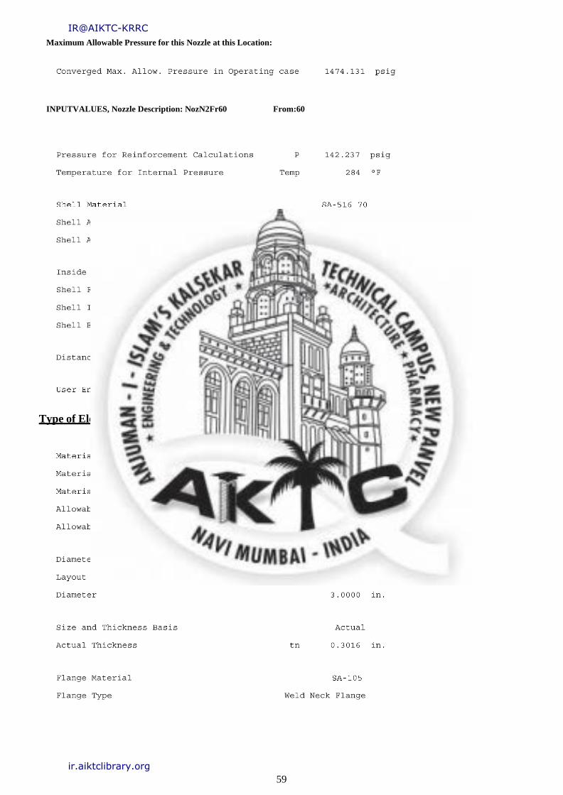
Maximum Allowable Pressure for this Nozzle at this Location:
INPUTVALUES, Nozzle Description: NozN2Fr60 From:60
Type of Element Connected to the Shell :Nozzle
IR@AIKTC-KRRC
ir.aiktclibrary.org

60
The Pressure Design option was Design Pressure+ static head.
Nozzle Sketch (may not represent actual weld type/configuration)
Insert/Set-in Nozzle No Pad, no Inside projection
Reinforcement CALCULATION, Description:NozN2Fr60
ASME Code, Section VIII,Div.1, 2015,UG-37 toUG-45
IR@AIKTC-KRRC
ir.aiktclibrary.org

61
Nozzle input data check completed without errors.
ReqdthkperUG-37(a) of Cylindrical Shell, Tr [Int. Press]
ReqdthkperUG-37(a) of Nozzle Wall, Trn [Int. Press]
UG-45Minimum Nozzle Neck Thickness Requirement:[Int. Press.]
The Drop for this Nozzle is: 0.4059 in.
The Cut Length for this Nozzle is, Drop + Ho + H +T: 7.0988in.
INPUT VALUES, Nozzle Description:NozN2Fr60 From:60
IR@AIKTC-KRRC
ir.aiktclibrary.org
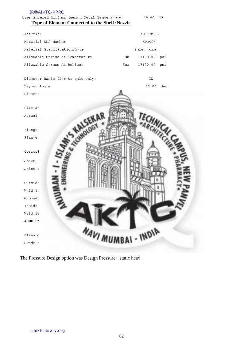
62
Type of Element Connected to the Shell :Nozzle
The Pressure Design option was Design Pressure+ static head.
IR@AIKTC-KRRC
ir.aiktclibrary.org
63
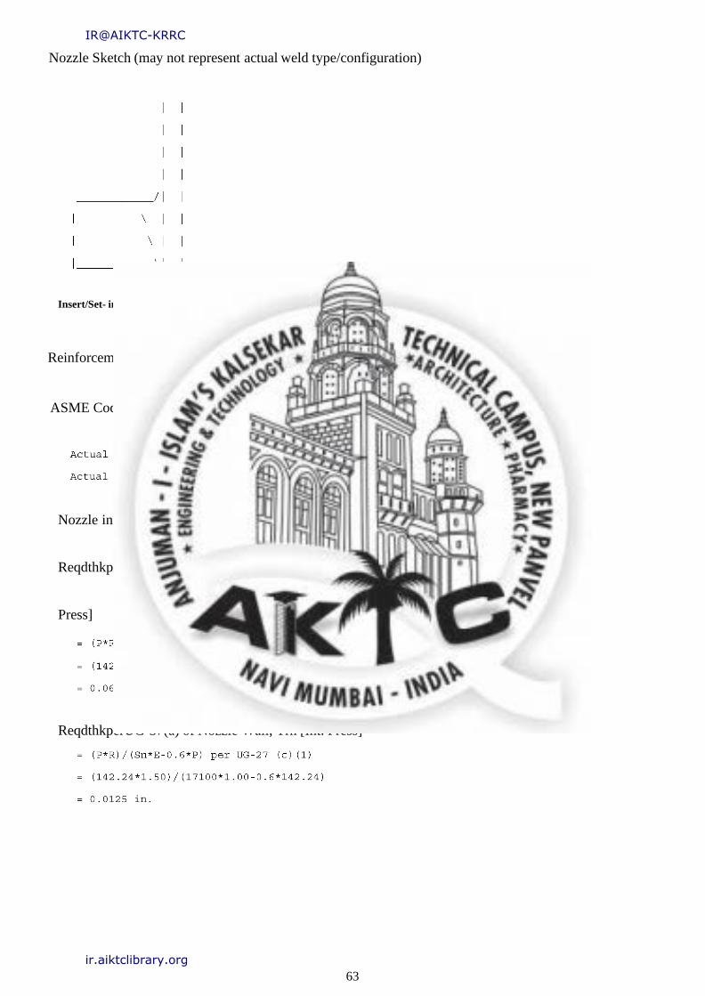
Nozzle Sketch (may not represent actual weld type/configuration)
Insert/Set- in Nozzle No Pad, no Inside projection
Reinforcement CALCULATION, Description: NozN2Fr60
ASME Code, Section VIII,Div.1, 2015,UG-37 toUG-45
Nozzle input data check completed without errors.
ReqdthkperUG-37(a) of Cylindrical Shell, Tr[Int.
Press]
ReqdthkperUG-37(a) of Nozzle Wall, Trn [Int. Press]
IR@AIKTC-KRRC
ir.aiktclibrary.org

64
UG- 45Minimum Nozzle
Neck Thickness
Requirement:[Int.
Press.]
Fig. 16 Nozzle
Nozzle Junction Minimum Design Metal Temperature (MDMT)Calculations:
MDMT of the Nozzle Neck to Flange Weld, Curve: B
Govrn. thk, tg = 0.302 , tr = 0.013 , c = 0.0000 in. , E* F
=
1.00StressRatio=tr*(E*)/(tg
-
c)=0.042,Temp.Reduction=
140
ResultsPerUW-16.1:
Maximum Allowable Pressure for this Nozzle at this Location:
The Drop for this Nozzle is: 0.1939 in.
The Cut Length for this Nozzle is, Drop + Ho+ H +T : 6.8869in.
IR@AIKTC-KRRC
ir.aiktclibrary.org
65
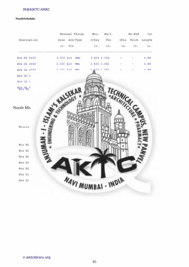
NozzleSchedule:
Nozzle Miscellaneous Data:
IR@AIKTC-KRRC
ir.aiktclibrary.org
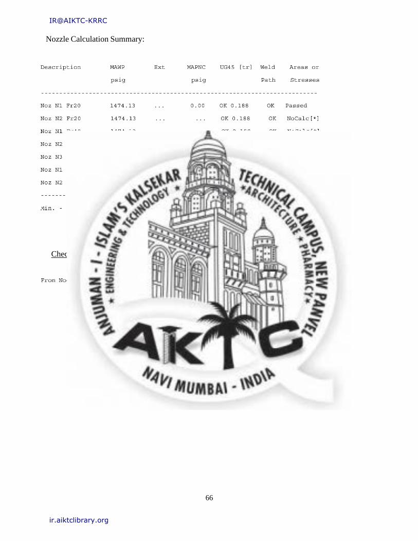
66
Nozzle Calculation Summary:
Check the Spatial Relationship between the Nozzles
IR@AIKTC-KRRC
ir.aiktclibrary.org
67
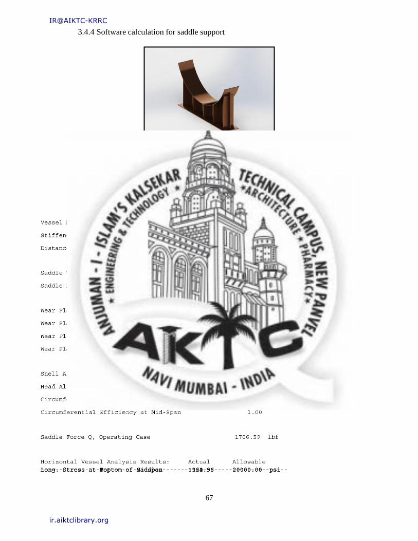
3.4.4 Software calculation for saddle support
Fig. 17 Saddle support
ASME Horizontal Vessel Analysis: Stresses for the Left Saddle
Input and Calculated Values:
IR@AIKTC-KRRC
ir.aiktclibrary.org
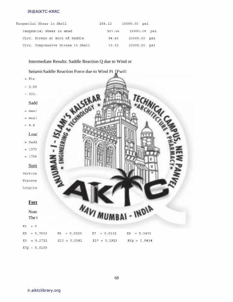
68
Intermediate Results: Saddle Reaction Q due to Wind or
Seismic Saddle Reaction Force due to Wind Ft [Fwt]:
Saddle Reaction Force due to Wind Fl or Friction[Fwl]:
Load Combination Results for Q+ Wind or Seismic[Q]:
Summary of Loads at the base of this Saddle:
Formulas and Substitutions for Horizontal Vessel Analysis:
Note: Wear Plate is Welded to the Shell, k = 0.1
The Computed K valuesfromTable4.15.1:
IR@AIKTC-KRRC
ir.aiktclibrary.org
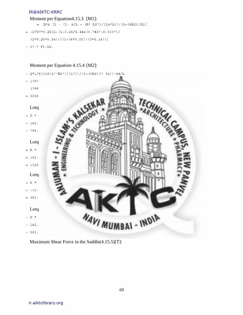
69
Moment per Equation4.15.3 [M1]:
Moment per Equation 4.15.4 [M2]:
Longitudinal Stress at Top of Shell(4.15.6) [Sigma1]:
Longitudinal Stress at Bottom of Shell(4.15.7) [Sigma2]:
Longitudinal Stress at Top of Shell at Support(4.15.8) [Sigma3]:
Longitudinal Stress at bottom of Shell at Support (4.15.9) [Sigma4]:
Maximum Shear Force in the Saddle(4.15.5)[T]:
IR@AIKTC-KRRC
ir.aiktclibrary.org

70
Shear Stress in the shell no rings, stiffened(4.15.15)[tau3]:
Shear Stress in the head, shell stiffened (4.15.16)[tau3*]:
Decay Length(4.15.22)[x1,x2]:
Circumferential Stress in shell, no rings(4.15.23)[sigma6]:
Effective reinforcing plate width(4.15.1)[B1]:
Wear Plate/Shell Stress ratio(4.15.29)[eta]:
Circumferential Stress at wear plate(4.15.26)[sigma6,r]:
IR@AIKTC-KRRC
ir.aiktclibrary.org
71
Circ. Comp. Stress at Horn of Saddle, L>=8Rm(4.15.27)[sigma7,r]:
Free Un-Restrained Thermal Expansion between the Saddles[Exp]:
ASME Horizontal Vessel Analysis: Stresses for the Right Saddle
(per ASME Sec. VIII Div.2 based on the Zick method.)
Input and Calculated Values:
IR@AIKTC-KRRC
ir.aiktclibrary.org

72
Intermediate Results: Saddle Reaction Q due to Wind or Seismic
Saddle Reaction Force due to Wind Ft[Fwt]:
Saddle Reaction Force due to Wind Fl or Friction[Fwl]:
Load Combination Results for Q+ Wind or Seismic[Q]:
IR@AIKTC-KRRC
ir.aiktclibrary.org
73
Summary of Load sat the base of this Saddle:
Formulas and Substitutions for Horizontal Vessel Analysis:
Note: Wear Plate is Welded to the Shell, k = 0.1
The Computed K valuesfromTable4.15.1:
The suffix 'p' denotes the values for a wear plate if It exists.
Note: Dimension a is less than Rm/2.
Moment per Equation4.15.3[M1]:
Moment per Equation4.15.4[M2]:
Longitudinal Stress at Top of Shell(4.15.6) [Sigma1]:
IR@AIKTC-KRRC
ir.aiktclibrary.org

74
Longitudinal Stress at Bottom of Shell(4.15.7) [Sigma2]:
Longitudinal Stress at Top of Shell at Support(4.15.8) [Sigma3]:
Longitudinal Stress at bottom of Shell at Support(4.15.9) [Sigma4]:
Maximum Shear Force in the Saddle(4.15.5)[T]:
Shear Stress in the shell no rings, stiffened(4.15.15)[tau3]:
Shear Stress in the head, shell stiffened (4.15.16)[tau3*]:
IR@AIKTC-KRRC
ir.aiktclibrary.org

75
Decay Length (4.15.22)[x1,x2]:
Circumferential Stress in shell, no rings(4.15.23)[sigma6]:
Effective reinforcing plate width(4.15.1)[B1]:
Wear Plate/Shell Stress ratio (4.15.29)[eta]:
Circumferential Stress at wear plate (4.15.26)[sigma6,r]:
Circ. Comp. Stress at Horn of Saddle, L>=8Rm(4.15.27)[sigma7,r]:
IR@AIKTC-KRRC
ir.aiktclibrary.org
76
3.4.5 Software calculation for tube sheet
Fig. 18 Tubesheet
Input Echo, Tube Sheet Item 1, Description: TUBESHEET
IR@AIKTC-KRRC
ir.aiktclibrary.org
77
IR@AIKTC-KRRC
ir.aiktclibrary.org
78
Additional Data for Fixed Tube sheet Exchangers
Additional Data for Tube sheets Extended as Flanges:
Additional Data for Gasketed Tube sheets:
IR@AIKTC-KRRC
ir.aiktclibrary.org

79
3.4.6 Software calculation for flange
Fig. 19 Flange
Flange Input Data Values Description: FLANGE :
FLANGE1
IR@AIKTC-KRRC
ir.aiktclibrary.org

80
IR@AIKTC-KRRC
ir.aiktclibrary.org
81
ASME Code, Section VIII, Division1,2015
Hub Small End Required Thickness due to Internal Pressure:
Hub Small End Hub MAWP:
Basic Flange and Bolt Loads:
Hydrostatic End Load due to Pressure [H]:
Contact Load on Gasket Surfaces[Hp]:
IR@AIKTC-KRRC
ir.aiktclibrary.org
82
Hydrostatic End Load at Flange ID [Hd]:
Pressure Force on Flange Face [Ht]:
Operating Bolt Load[Wm1]:
Gasket Seating Bolt Load[Wm2]:
Required Bolt Area[Am]:
ASME Maximum Circumferential Spacing between Bolts per App.2eq.(3)[Bs max]:
Actual Circumferential Bolt Spacing [Bs]:
ASME Moment Multiplier for Bolt Spacing per App.2 eq.(7) [Bsc]:
IR@AIKTC-KRRC
ir.aiktclibrary.org

83
Flange Input Data Values Description: New Flange :
FLANGE2
IR@AIKTC-KRRC
ir.aiktclibrary.org

84
ASME Code, Section VIII, Division1,2015
Hub Small End Required Thickness due to Internal Pressure:
Hub Small End Hub MAWP:
IR@AIKTC-KRRC
ir.aiktclibrary.org
85
Basic Flange and Bolt Loads:
Hydrostatic End Load due to Pressure[H]:
Contact Load on Gasket Surfaces[Hp]:
Hydrostatic End Load at Flange ID [Hd]:
Pressure Force on Flange Face[Ht]:
Operating Bolt Load[Wm1]:
Gasket Seating Bolt Load[Wm2]:
Required Bolt Area[Am]:
ASME Maximum Circumferential Spacing between Bolts per App.2eq.(3)[Bs max]:
IR@AIKTC-KRRC
ir.aiktclibrary.org
86
Actual Circumferential Bolt Spacing[Bs]:
ASME Moment Multiplier for Bolt Spacing per App.2 eq.(7) [Bsc]:
IR@AIKTC-KRRC
ir.aiktclibrary.org

87
CHAPTER 04
MANUFACTURING
IR@AIKTC-KRRC
ir.aiktclibrary.org
88
4.1 Roller Machine
A plate rolling machine is a machine that will roll different kinds of metal sheet into a round or
conical shape. It can be also called a roll bending machine, plate bending machine or rolling machine.
A plate rolling machine is a mechanical jig having three rollers used to form a metal bar into a circular
arc. The rollers freely rotate about three parallel axes, which are arranged with uniform horizontal
spacing. Two outer rollers, usually immobile, cradle the bottom of the material while the inner roller,
whose position is adjustable, presses on the topside of the material. The material to be shaped is
suspended between the rollers. The end rollers support the bottom side of the bar and have a matching
contour (inverse shape) to it in order to maintain the cross-sectional shape. Likewise, the middle roller
is forced against the topside of the bar and has a matching contour to it.
On contact with the sheet, the roll contacts on two points and it rotates as the forming process bends
the sheet. This bending method is typically considered non-marking forming process suitable opre-
painted or easily marred surfaces. This bending process can produce angles greater than 90° in a single
hit on standard press brakes process.
Fig. 20 Rolling machine
IR@AIKTC-KRRC
ir.aiktclibrary.org

89
4.2 Hydraulic press
A hydraulic press is a device using a hydraulic cylinder to generate a compressive force. It uses the
hydraulic equivalent of a mechanical lever, and was also known as a Bramah press after the inventor,
Joseph Bramah, of England He invented and was issued a patent on this press in 1795. He studied the
existing literature on the motion of fluids and put this knowledge into the development of the press.
The hydraulic press depends on Pascal's principle he pressure throughout a closed system is constant.
One part of the system is a piston acting as a pump, with a modest mechanical force acting on a small
cross- sectional area; the other part is a piston with a larger area which generates a correspondingly
large mechanical force. Only small diameter tubing is needed if the pump is separated from the press
cylinder.
Pascal's law: Pressure on a confined fluid is transmitted undiminished and acts with equal force on
equal areas and at 90 degrees to the container wall. A small effort force acts on a small piston. This
creates a pressure which is transferred through the hydraulic fluid to large a large piston.
Fig.21 Hydraulic press
IR@AIKTC-KRRC
ir.aiktclibrary.org
90
4.3 Gas tungsten arc welding
Gas tungsten arc welding (GTAW), also known as tungsten inert gas (TIG) welding, is an arc
welding process that uses an on-consumable tungsten electrode to produce the weld. The weld area
and electrode is protected from oxidation or other atmospheric contamination by an inert shielding gas
(argon or helium), and a filler metal is normally used, though some welds, known as auto genus
welds, do not require it. A constant-current welding power supply produces electrical energy, which is
conducted across the arc through a column of highly ionized gas and metal vapors known as a plasma.
Before welding a spot of a weld is create on the portion of the welding area. It is done keep the two
edges in contact with each other.
Fig. 22 Gas tungsten arc welding machine
IR@AIKTC-KRRC
ir.aiktclibrary.org
91
CHAPTER 05
INSPECTION
IR@AIKTC-KRRC
ir.aiktclibrary.org
92
5.1 Radiography test
Industrial radiography is a method of non-destructive testing where many types of manufactured
components can be examined to verify the internal structure and integrity of the specimen.
Industrial Radiography can be performed utilizing either X-rays or gamma rays. Both are forms
of electromagnetic radiation. The difference between various forms of electromagnetic energy is
related to the wavelength. X and gamma rays have the shortest wavelength and this property leads
to the ability to penetrate, travel through, and exit various materials such as carbon steel and other
metals.
The beam of radiation must be directed to the middle of the section under examination and must
be normal to the material surface at that point, except in special techniques where known defects
are best revealed by a different alignment of the beam. The length of weld under examination for
each exposure shall be such that the thickness of the material at the diagnostic extremities,
measured in the direction of the incident beam, does not exceed the actual thickness at that point by
more than 6%. The specimen to be inspected is placed between the source of radiation and the
detecting device, usually the film in a light tight holder or cassette, and the radiation is allowed to
penetrate the part for the required length of time to be adequately recorded.
The result is a two-dimensional projection of the part onto the film, producing a latent image of
varying densities according to the amount of radiation reaching each area. It is known as a radio
graph, as distinct from a photograph produced by light. Because film is cumulative in its response
(the exposure increasing as it absorbs more radiation), relatively weak radiation can be detected
by prolonging the exposure until the film can record an image that will be visible after
development
Before commencing a radiographic examination, it is always advisable to examine the component
with one's own eyes, to eliminate any possible external defects. If the surface of a weld is too
irregular, it may be desirable to grind it to obtain a smooth finish, but this is likely to be limited
to those cases in which the surface irregularities (which will be visible on the radiograph) may
make detecting internal defects difficult.
IR@AIKTC-KRRC
ir.aiktclibrary.org
93
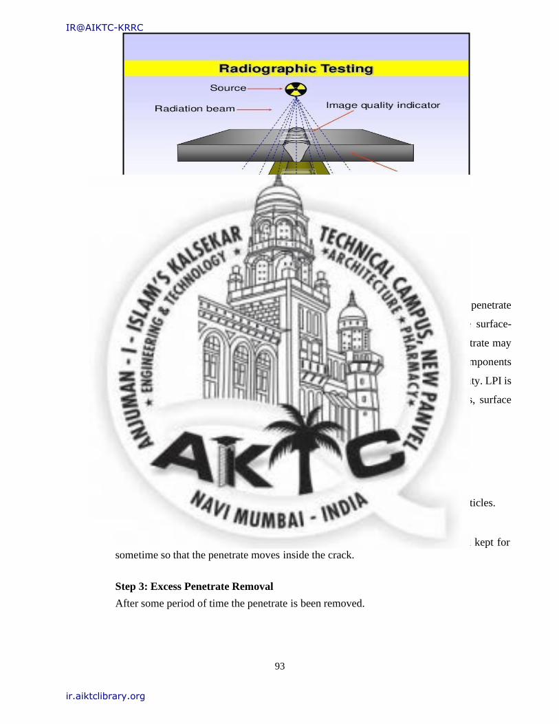
Fig. 23 Radiography testing
5.1.1 Dye Penetrate Testing
Dye penetrate inspection (DPI), also called liquid penetrate inspection (LPI) or penetrate
testing (PT), is a widely applied and low-cost inspection method used to locate surface-
breaking defects in all non-porous materials (metals, plastics, or ceramics). The penetrate may
be applied to all non- ferrous materials and ferrous materials, although for ferrous components
magnetic- particle inspection is often used instead for its sub surface detection capability. LPI is
used to detect casting, forging and welding surface defects such as hairline cracks, surface
porosity, leaks in new products, and fatigue cracks on in-service components.
Procedure for DP test
Step 1: Pre-cleaning
Firstly, the material is been cleaned with the cloth due to the presence of dust particles.
Step 2: Application of Penetrate
Penetrate is then applied on the material where the inspection is to be done and kept for
some time so that the penetrate moves inside the crack.
Step 3: Excess Penetrate Removal
After some period of time the penetrate is been removed.
IR@AIKTC-KRRC
ir.aiktclibrary.org

94
Step 4: Application of Developer
After removing the penetrate the developer is applied on the material where the penetrate is
has applied on the stare a the developer removes the penetrate from the crack.
Step 5: Inspection
After sometime of applied developer the material is been taken under the white light to see
the crack on the material as the developer take out the penetrate out of the crack.
Step 6: Post Cleaning
As the inspection gets over the material is then cleaned with clean cloth and can be used for
its respective work.
Fig. 24 Dye penetrate testing
IR@AIKTC-KRRC
ir.aiktclibrary.org
95
5.2 Hydrostatic test
A hydrostatic test is a way in which pressure vessels such as pipelines, plumbing, gas cylinders, boilers
and fuel tanks can be tested for strength and leaks. The test involves filling the vessel or pipe system
with a liquid, usually water, which may be dyed to aid in visual leak detection, and pressurization of
the vessel to the specified test pressure. Pressure tightness can be tested by shutting off the supply
valve and observing whether there is a pressure loss. The location of a leak can be visually identified
more easily if the water contains a colorant. Strength is usually tested by measuring permanent
deformation of the container. Hydrostatic testing is the most common method employed for testing
pipes and pressure vessels. Using this test helps maintain safety standards and durability of a vessel
over time. Newly manufactured pieces are initially qualified using the hydrostatic test. They are then
re-qualified at regular intervals using the proof pressure test which is also called the modified
hydrostatic test. Testing of pressure vessels for transport and storage of gases is very important because
such containers can explode if they fail under pressure.
Hydrostatic tests are conducted under the constraints of either the industry's or the customer's
specifications, or may be required by law. The vessel is filled with a nearly incompressible liquid-
usually water or oil pressurized to test pressure, and examined for leaks or permanent changes in shape.
Red or fluorescent dyes may be added to the water to make leaks easier to see. The test pressure is
always considerably higher than the operating pressure to give a factor of safety. This factor of safety
is typically 166.66%, 143% or 150% of the designed working pressure, depending on the regulations
that apply.
Fig. 25 hydro testing machine
IR@AIKTC-KRRC
ir.aiktclibrary.org

96
CHAPTER 06
RESULT
IR@AIKTC-KRRC
ir.aiktclibrary.org
97
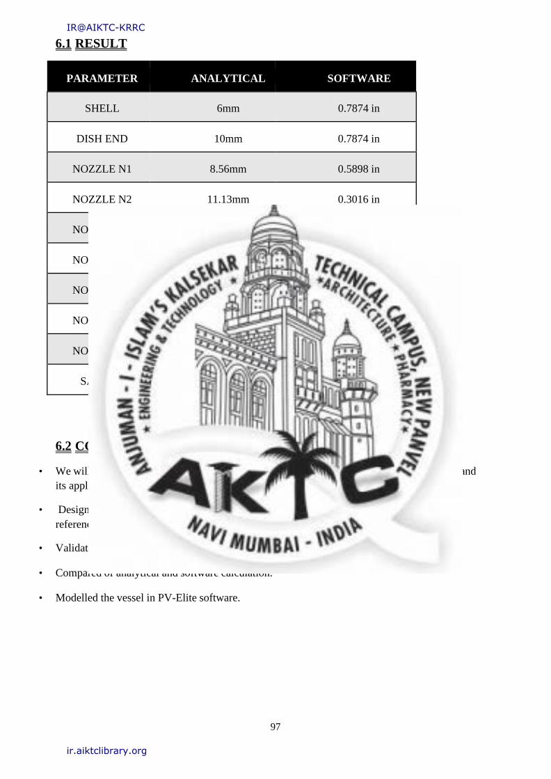
6.1 RESULT
PARAMETER ANALYTICAL SOFTWARE
SHELL 6mm 0.7874 in
DISH END 10mm 0.7874 in
NOZZLE N1 8.56mm 0.5898 in
NOZZLE N2 11.13mm 0.3016 in
NOZZLE N3 11.13mm 0.3016 in
NOZZLE N4 11.13mm 0.3016 in
NOZZLE N5 11.13mm 0.3016 in
NOZZLE N6 11.13mm 0.3016 in
NOZZLE N7 8.56mm 0.5898 in
SADDLE 1.483KN 333.6 lbf
Table 06. Result
6.2 CONCLUSION
• We will be able to understand components of General Arrangement of AES heat exchanger and
its applications.
• Designed the components of industrial AES Heat Exchanger by analytical method in
reference with A.S.M.E and T.E.M.A
• Validated the design using software PV-Elite version 2019.
• Compared of analytical and software calculation.
• Modelled the vessel in PV-Elite software.
IR@AIKTC-KRRC
ir.aiktclibrary.org
98
CHAPTER 07
COST
ESTIMATION
IR@AIKTC-KRRC
ir.aiktclibrary.org
99
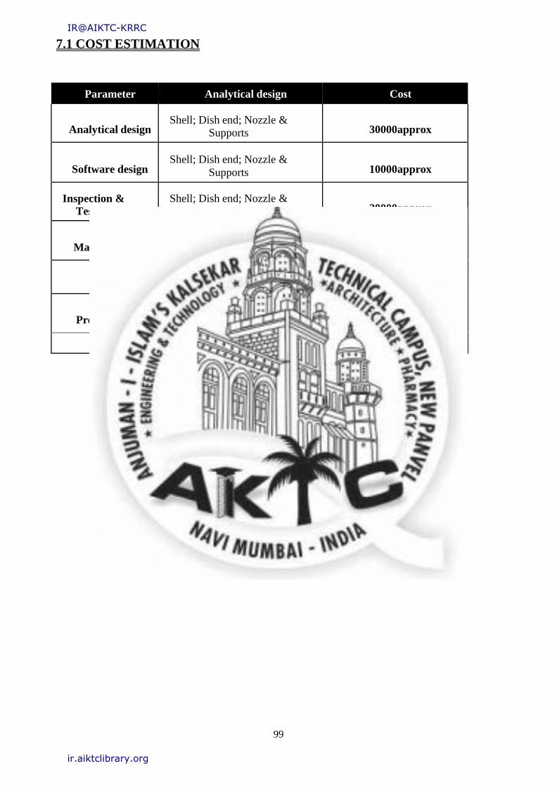
7.1 COST ESTIMATION
Parameter Analytical design Cost
Analytical design Shell; Dish end; Nozzle &
Supports
30000approx
Software design Shell; Dish end; Nozzle &
Supports
10000approx
Inspection &
Testing
Shell; Dish end; Nozzle & Supports
20000approx
Manufacturing Shell; Dish end; Nozzle &
Supports
64000approx
GST 14% 21000
Project report Shell; Dish end; Nozzle &
Supports
5000approx
Total 150000/-
Table 07. Cost Estimation
IR@AIKTC-KRRC
ir.aiktclibrary.org

100
CHAPTER 08
REFERENCES
IR@AIKTC-KRRC
ir.aiktclibrary.org
101
8.1 References
8.1.1 Books
1. Working with Heat Exchanger by J. P. Gupta.
2. Pressure Vessel Design Lubrication and Test by Esmael Kaynejad.
3. ASME boiler and pressure vessel code by The American Society Of Mechanical
Engineers (ASME).
4. Standards of TEMA by TEMA.IN
5. Pressure Vessel Design Manual by Dennis Moss
8.1.2 Links
1. https://issuu.com/ijteee/docs/vibration-analysis-of-aes-type-shel
2. https://www.ijert.org/research/design-fabrication-and-testing-of-shell-and- tube-heat-
exchanger-for-heat-recovery-from-hydraulic-oil- IJERTV6IS070289.pdf
3. https://www.researchgate.net/publication/305115678_Thermal_design_and_a
nalysis_of_shell_and_tube_heat_exchanger_for_various_mass_flow_rate_at_
different_fouling_conditions_in_Xchanger-HTRI_50
4. http://www.wermac.org/equipment/heatexchanger_part5.html
5. http://www.oilngasseparator.info/oil-handling-surfacefacilities/heat- exchanger-
types.html#:~:text=An%20AES%20classification%20for%20a,designates%2
0a%20one%2Dpass%20shell.
6. https://www.researchgate.net/publication/318765038_Design_Fabrication_an
d_Testing_of_Shell_and_Tube_Heat_Exchanger_for_Heat_Recovery_from_
Hydraulic_Oil
7. https://media.neliti.com/media/publications/264793-mechanical-design-of- shell-and-
tube-type-8f7a58e7.pdf
IR@AIKTC-KRRC
ir.aiktclibrary.org
Copyright © 2022 FDOKUMEN