Deliverable D 9.1 Design Specification for the Target ...
75
Shift2Rail –ASSETS4RAIL GA 826250 P a g e 1 | 75 This project has received funding from the Shift2Rail Joint Undertaking under the European Union’s Horizon 2020 research and innovation programme under grant agreement no. 826250 Assets4Rail). Deliverable D 9.1 Design Specification for the Target Signalling Systems Reviewed: (yes/no) Project acronym: Assets4Rail Starting date: 01/12/2018 Duration (in months): 3 months Call (part) identifier: H2020-S2RJU-2018 Grant agreement no: 826250 Due date of deliverable: Month 9 Actual submission date: 07-10-2019 Responsible/Author: SENER Dissemination level: CO Status: Draft Ref. Ares(2020)66068 - 07/01/2020
-
Upload
khangminh22 -
Category
Documents
-
view
1 -
download
0
Transcript of Deliverable D 9.1 Design Specification for the Target ...
Shift2Rail –ASSETS4RAIL
G A 8 2 6 2 5 0 P a g e 1 | 75
This project has received funding from the Shift2Rail JointUndertaking under the European Union’s Horizon 2020research and innovation programme under grantagreement no. 826250 Assets4Rail).
Deliverable D 9.1Design Specification for the Target Signalling
Systems
Reviewed: (yes/no)
Project acronym: Assets4Rail
Starting date: 01/12/2018
Duration (in months): 3 months
Call (part) identifier: H2020-S2RJU-2018
Grant agreement no: 826250
Due date of deliverable: Month 9
Actual submission date: 07-10-2019
Responsible/Author: SENER
Dissemination level: CO
Status: Draft
Ref. Ares(2020)66068 - 07/01/2020
Shift2Rail –ASSETS4RAIL
G A 8 2 6 2 5 0 P a g e 2 | 75
This project has received funding from the Shift2Rail JointUndertaking under the European Union’s Horizon 2020research and innovation programme under grantagreement no. 826250 Assets4Rail).
Document history
Revision Date Description
1 First issue
Report contributors
Name Beneficiary Short Name Details of contribution
Sener Ingenieria Y Sistemas S.A. SENER All sections
Technische Universitat Berlin TUB Reviewed
Università degli Studi di Roma La Sapienza DICEA Reviewed
Witt Industrieelektronik Gmbh WITT Feasibility Analysis
Ab Lietuvos Gelezinkeliai LiRa Reviewed
Shift2Rail –ASSETS4RAIL
G A 8 2 6 2 5 0 P a g e 3 | 75
This project has received funding from the Shift2Rail JointUndertaking under the European Union’s Horizon 2020research and innovation programme under grantagreement no. 826250 Assets4Rail).
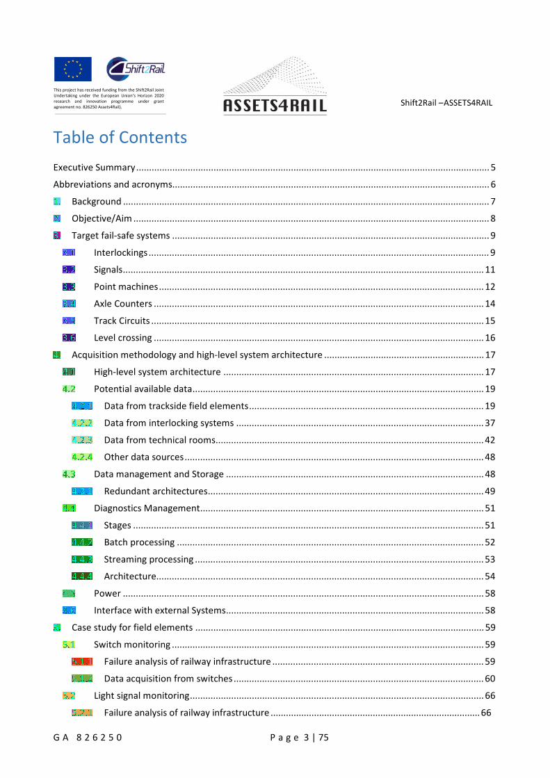
Table of Contents
Executive Summary......................................................................................................................................... 5
Abbreviations and acronyms........................................................................................................................... 6
Background .............................................................................................................................................. 7
Objective/Aim .......................................................................................................................................... 8
Target fail-safe systems ........................................................................................................................... 9
Interlockings .................................................................................................................................... 9
Signals............................................................................................................................................11
Point machines..............................................................................................................................12
Axle Counters ................................................................................................................................14
Track Circuits .................................................................................................................................15
Level crossing ................................................................................................................................16
Acquisition methodology and high-level system architecture ..............................................................17
High-level system architecture .....................................................................................................17
Potential available data.................................................................................................................19
Data from trackside field elements...........................................................................................19
Data from interlocking systems ................................................................................................37
Data from technical rooms........................................................................................................42
Other data sources....................................................................................................................48
Data management and Storage ....................................................................................................48
Redundant architectures...........................................................................................................49
Diagnostics Management..............................................................................................................51
Stages ........................................................................................................................................51
Batch processing .......................................................................................................................52
Streaming processing ................................................................................................................53
Architecture...............................................................................................................................54
Power ............................................................................................................................................58
Interface with external Systems....................................................................................................58
Case study for field elements ................................................................................................................59
Switch monitoring .........................................................................................................................59
Failure analysis of railway infrastructure ..................................................................................59
Data acquisition from switches .................................................................................................60
Light signal monitoring..................................................................................................................66
Failure analysis of railway infrastructure ..................................................................................66
Shift2Rail –ASSETS4RAIL
G A 8 2 6 2 5 0 P a g e 4 | 75
This project has received funding from the Shift2Rail JointUndertaking under the European Union’s Horizon 2020research and innovation programme under grantagreement no. 826250 Assets4Rail).
Data acquisition from light signals ............................................................................................66
Train detection assets monitoring ................................................................................................67
Failure analysis of railway infrastructure ..................................................................................67
Data acquisition from train detection assets ............................................................................69
Level crossings monitoring............................................................................................................70
Failure analysis of railway infrastructure ..................................................................................70
Data acquisition from level crossings........................................................................................70
Conclusions ............................................................................................................................................73
References .............................................................................................................................................74

Shift2Rail –ASSETS4RAIL
G A 8 2 6 2 5 0 P a g e 5 | 75
This project has received funding from the Shift2Rail JointUndertaking under the European Union’s Horizon 2020research and innovation programme under grantagreement no. 826250 Assets4Rail).
Executive Summary
Presenting the identification of the target signaling systems and specifications of the data acquisitionprocess for different types of data.
Shift2Rail –ASSETS4RAIL
G A 8 2 6 2 5 0 P a g e 6 | 75
This project has received funding from the Shift2Rail JointUndertaking under the European Union’s Horizon 2020research and innovation programme under grantagreement no. 826250 Assets4Rail).
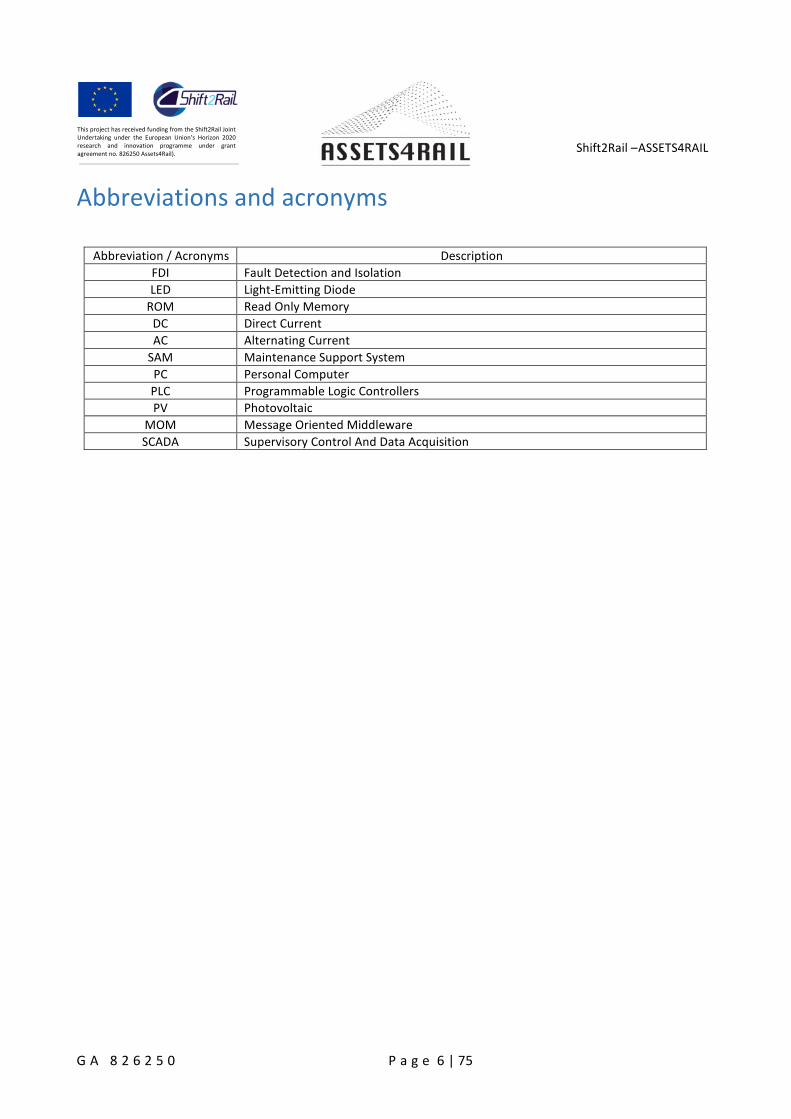
Abbreviations and acronyms
Abbreviation / Acronyms Description
FDI Fault Detection and Isolation
LED Light-Emitting Diode
ROM Read Only Memory
DC Direct Current
AC Alternating Current
SAM Maintenance Support System
PC Personal Computer
PLC Programmable Logic Controllers
PV Photovoltaic
MOM Message Oriented Middleware
SCADA Supervisory Control And Data Acquisition

Shift2Rail –ASSETS4RAIL
G A 8 2 6 2 5 0 P a g e 7 | 75
This project has received funding from the Shift2Rail JointUndertaking under the European Union’s Horizon 2020research and innovation programme under grantagreement no. 826250 Assets4Rail).
Background
Monitoring the conditions of railway asset is essential for ensuring the railway safety. Condition monitoring
can be a part of the well-established area of Fault Detection and Isolation (or Identification). Condition
monitoring is mainly applicable to system that deteriorate in time. The aim of condition monitoring is to
detect and isolate deterioration before it causes a failure.
A condition monitoring system is usually used to provide a diagnosis of failure for maintenance, in situations
where the measured features exceed some predetermined thresholds or show a specific deviation from
normal conditions. On the other hand, the data acquired can be used as a prognosis for predicting future
failures and the remaining useful life.
There are many assets in the railway around the world (points, track circuits, signals...). Efficient and timely
maintenance interventions are essential to ensure trains operate to the published timetable without delays
or interruptions to service.
The challenge therefore is being able to monitor key assets with real time information that will support:
right time interventions
changes in the existing maintenance regimes
re-design of an asset.
Monitoring as it was traditionally known is reinvented to satisfy needs and more demanding safety andproduction quality policies. Modern monitoring processes should include not only the ability to receive dataabout the critical points of the process or chain of services, but also the possibility of predicting possibleproblems that could endanger the functioning of a system or even the physical integrity of the system orthe people around him.
Shift2Rail –ASSETS4RAIL
G A 8 2 6 2 5 0 P a g e 8 | 75
This project has received funding from the Shift2Rail JointUndertaking under the European Union’s Horizon 2020research and innovation programme under grantagreement no. 826250 Assets4Rail).
Objective/Aim
The objective of this work package is to design and propose a set of acquisition and data collection schemes
for safety-critical systems. These schemes must be developed for the trackside signalling systems only.
These set of monitoring, inspection and data collection systems shall not thread the safety critical
functionalities of the “under inspection” equipment. The proposed solution will be a modular hardware
and software platform capable to be integrated within the equipment to be monitored.
This report presents the results ofTask 9.1 Design Specifications and Acquisition Methodologies, which aimsto
identify the target signaling systems to be monitored.
formulate the overall data acquisition concept and setup the high-level system architecture
identify the specific data acquisition methods from the field elements
Shift2Rail –ASSETS4RAIL
G A 8 2 6 2 5 0 P a g e 9 | 75
This project has received funding from the Shift2Rail JointUndertaking under the European Union’s Horizon 2020research and innovation programme under grantagreement no. 826250 Assets4Rail).
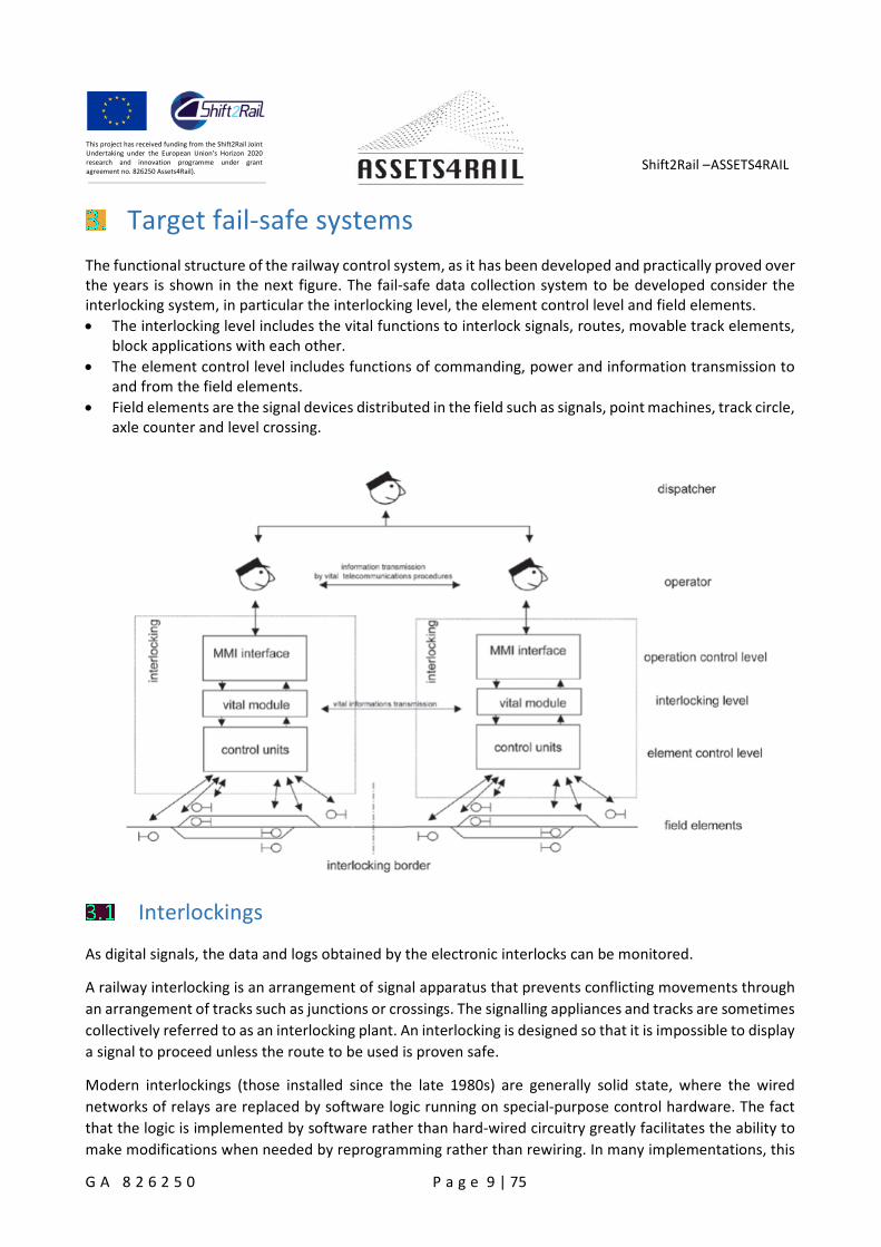
Target fail-safe systems
The functional structure of the railway control system, as it has been developed and practically proved overthe years is shown in the next figure. The fail-safe data collection system to be developed consider theinterlocking system, in particular the interlocking level, the element control level and field elements.
The interlocking level includes the vital functions to interlock signals, routes, movable track elements,block applications with each other.
The element control level includes functions of commanding, power and information transmission toand from the field elements.
Field elements are the signal devices distributed in the field such as signals, point machines, track circle,axle counter and level crossing.
Interlockings
As digital signals, the data and logs obtained by the electronic interlocks can be monitored.
A railway interlocking is an arrangement of signal apparatus that prevents conflicting movements through
an arrangement of tracks such as junctions or crossings. The signalling appliances and tracks are sometimes
collectively referred to as an interlocking plant. An interlocking is designed so that it is impossible to display
a signal to proceed unless the route to be used is proven safe.
Modern interlockings (those installed since the late 1980s) are generally solid state, where the wired
networks of relays are replaced by software logic running on special-purpose control hardware. The fact
that the logic is implemented by software rather than hard-wired circuitry greatly facilitates the ability to
make modifications when needed by reprogramming rather than rewiring. In many implementations, this
Shift2Rail –ASSETS4RAIL
G A 8 2 6 2 5 0 P a g e 10 | 75
This project has received funding from the Shift2Rail JointUndertaking under the European Union’s Horizon 2020research and innovation programme under grantagreement no. 826250 Assets4Rail).
vital logic is stored as firmware or in ROM that cannot be easily altered to both resist unsafe modification
and meet regulatory safety testing requirements.
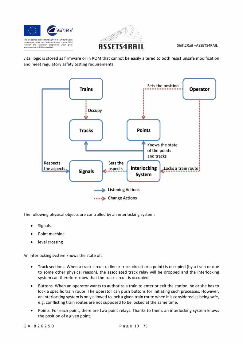
The following physical objects are controlled by an interlocking system:
Signals.
Point machine
level crossing
An interlocking system knows the state of:
Track sections. When a track circuit (a linear track circuit or a point) is occupied (by a train or dueto some other physical reason), the associated track relay will be dropped and the interlockingsystem can therefore know that the track circuit is occupied.
Buttons. When an operator wants to authorize a train to enter or exit the station, he or she has tolock a specific train route. The operator can push buttons for initiating such processes. However,an interlocking system is only allowed to lock a given train route when it is considered as being safe,e.g. conflicting train routes are not supposed to be locked at the same time.
Points. For each point, there are two point relays. Thanks to them, an interlocking system knowsthe position of a given point.
Shift2Rail –ASSETS4RAIL
G A 8 2 6 2 5 0 P a g e 11 | 75
This project has received funding from the Shift2Rail JointUndertaking under the European Union’s Horizon 2020research and innovation programme under grantagreement no. 826250 Assets4Rail).
The electronic interlockings use different modules in order to manage the data from track circuits, points,signals... These modules are the following:
Module for power and control signals: This module is used for power and checking of the bulbs ofthe signals, conventional lamps, LED diodes or as alphanumeric. This module is programmable sothat it is controlled by current detection if the signal is ON, OFF, or with an incidence (fused bulb,derivations…) The module can give fixed or intermittent outputs and acts as a final power stage forthe lighting of the signals, checking the fused bulbs.
Module of security entries for the verification of elements: This module is used to receive theinformation and validate each entry from the different trackside elements, except the signals, suchas points, track circuits, axle counters, level crossings… It consists of DC input cards and activeredundancy in the corresponding part of the vital logic.
Module of security outputs for the control of elements: This module is used for the sending of vitaloutputs for the control of field elements except signals, such as points, electric locks, and relationswith level crossings… The electronic part of this module consists of DC output cards and activeredundancy in the corresponding part of the vital logic.
Point control module: This group of units are used for the control of deviations equipped withelectric or electrohydraulic points, depending on the characteristics thereof and the number ofassociated points. It will be composed of DC input cards that receive the information from thesafety output module for the control of the field elements and the DC output cards that act on therelays or the galvanically isolated contactors. The module includes the electromechanical interfacenecessary to tackle the point. For the deviations equipped with multiple drives, this moduleincludes the additional relay equipment for the synchronization and control of the sequentialmovement of the motors.
The input values are safely and logically processed in the interlocking process modules.
Signals
Signals are used to control the railway traffic. There are several kinds of signals. Some signals are used forshunting while other signals are used for controlling the ordinary traffic on the rails.
Stop. The train must stop in front of the signal. The stop aspect will be indicated by a red light,sometimes combined with a yellow light.
Drive. The train is allowed to pass the given signal, but the train driver must expect to stop at thenext signal. The drive aspect is indicated by a green light, sometimes combined with a yellow light.
Drive through. The train is allowed to pass the given signal and it should expect drive or drivethrough at the next signal. The drive through aspect is either indicated by two green lights or ablinking green light.
There are several signal types indicating the role of the signal. For instance, entrance signals control the
entry of a station by displaying the appropriate aspect and exit signals control the exit of a station.
The typical electric maintenance of the signals is the next:
Shift2Rail –ASSETS4RAIL
G A 8 2 6 2 5 0 P a g e 12 | 75
This project has received funding from the Shift2Rail JointUndertaking under the European Union’s Horizon 2020research and innovation programme under grantagreement no. 826250 Assets4Rail).
ID Maintenance Operation Periodicity
1Check the ground connection of all signals and alldistribution boxes
Annual
2 Checking bulbs and replacing fused bulbs. Quarterly
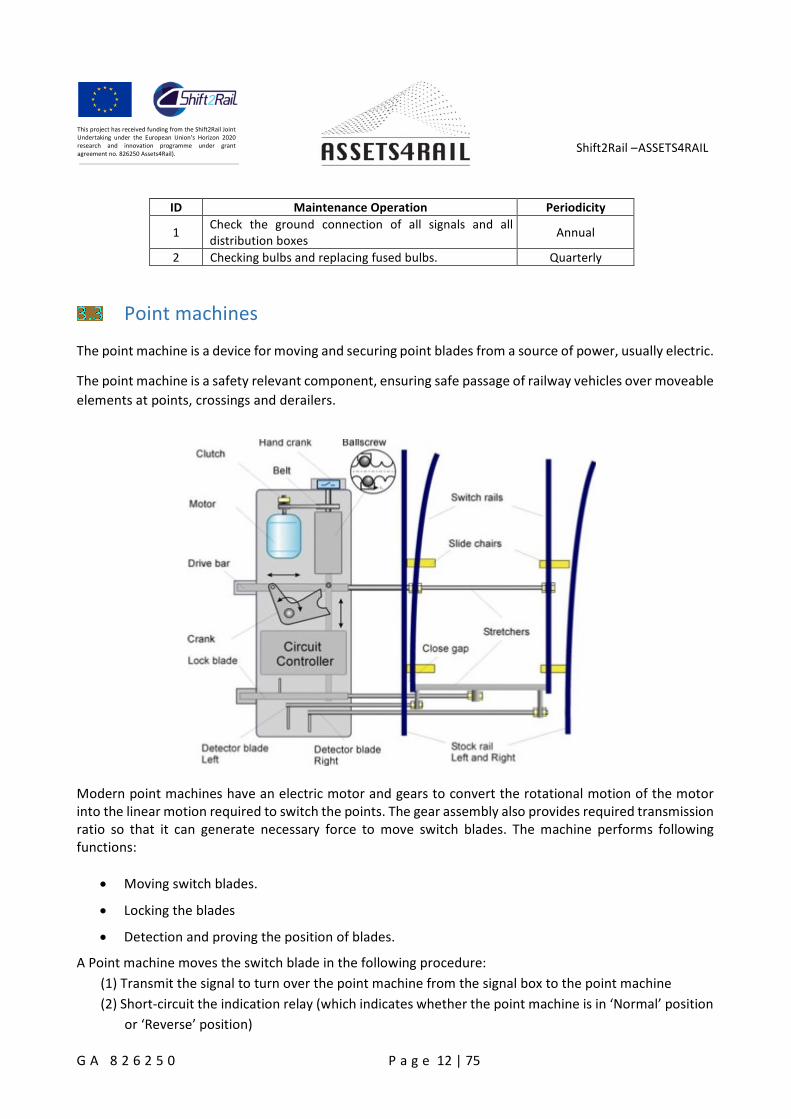
Point machines
The point machine is a device for moving and securing point blades from a source of power, usually electric.
The point machine is a safety relevant component, ensuring safe passage of railway vehicles over moveable
elements at points, crossings and derailers.
Modern point machines have an electric motor and gears to convert the rotational motion of the motorinto the linear motion required to switch the points. The gear assembly also provides required transmissionratio so that it can generate necessary force to move switch blades. The machine performs followingfunctions:
Moving switch blades.
Locking the blades
Detection and proving the position of blades.
A Point machine moves the switch blade in the following procedure:
(1) Transmit the signal to turn over the point machine from the signal box to the point machine
(2) Short-circuit the indication relay (which indicates whether the point machine is in ‘Normal’ position
or ‘Reverse’ position)
Shift2Rail –ASSETS4RAIL
G A 8 2 6 2 5 0 P a g e 13 | 75
This project has received funding from the Shift2Rail JointUndertaking under the European Union’s Horizon 2020research and innovation programme under grantagreement no. 826250 Assets4Rail).
(3) Complete the electrical circuit to move the motor
(4) Unlock the point machine with the locking mechanism
(5) Move the drive rod until the switch blade is fully moved
(6) Lock the point machine with the locking mechanism
(7) Break the electrical circuit to move the motor and complete indication circuit
(8) Indication relay operates and the signal indicating the position of the point machine is transmitted
from the point machine to the signal box.
3.3.1.1 Electro - Hydraulic
The typical electric maintenance of the electro-hydraulic points is the next:
ID Maintenance Operation Periodicity
Engine
1Verification of the existence of indication of dangerouscurrent indication.
Anual
2Check the implementation of the ground of the electricdrive of the point.
Anual
3 Check the correct position of the drive. Anual
4Checking the operation of the electricaldisconnection/connection through the crank and that iscorrectly engaged.
Anual
3.3.1.2 Electromechanical
The typical electric maintenance of the electromechanical points is the next:
ID Maintenance Operation Periodicity
Engine
Shift2Rail –ASSETS4RAIL
G A 8 2 6 2 5 0 P a g e 14 | 75
This project has received funding from the Shift2Rail JointUndertaking under the European Union’s Horizon 2020research and innovation programme under grantagreement no. 826250 Assets4Rail).
1 Check the ground of the electric point. Anual
2 Check the correct position of the blades. Anual
3Check that current cut-of and blocking device is workingcorrectly.
Anual
4Measure the value of the engine current in the movementfrom normal to inverted position and vice versa, registeringthe values.
Anual
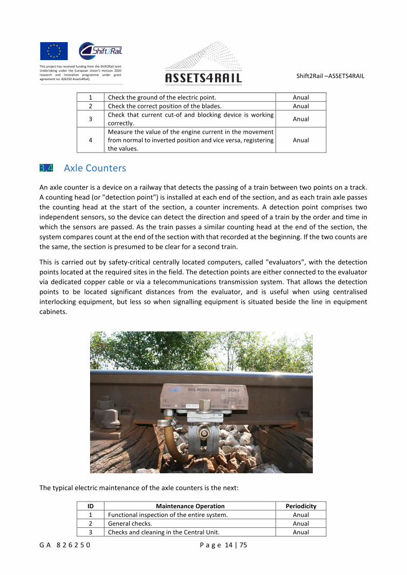
Axle Counters
An axle counter is a device on a railway that detects the passing of a train between two points on a track.
A counting head (or "detection point") is installed at each end of the section, and as each train axle passes
the counting head at the start of the section, a counter increments. A detection point comprises two
independent sensors, so the device can detect the direction and speed of a train by the order and time in
which the sensors are passed. As the train passes a similar counting head at the end of the section, the
system compares count at the end of the section with that recorded at the beginning. If the two counts are
the same, the section is presumed to be clear for a second train.
This is carried out by safety-critical centrally located computers, called "evaluators", with the detection
points located at the required sites in the field. The detection points are either connected to the evaluator
via dedicated copper cable or via a telecommunications transmission system. That allows the detection
points to be located significant distances from the evaluator, and is useful when using centralised
interlocking equipment, but less so when signalling equipment is situated beside the line in equipment
cabinets.
The typical electric maintenance of the axle counters is the next:
ID Maintenance Operation Periodicity
1 Functional inspection of the entire system. Anual
2 General checks. Anual
3 Checks and cleaning in the Central Unit. Anual
Shift2Rail –ASSETS4RAIL
G A 8 2 6 2 5 0 P a g e 15 | 75
This project has received funding from the Shift2Rail JointUndertaking under the European Union’s Horizon 2020research and innovation programme under grantagreement no. 826250 Assets4Rail).
4 Checks in the Road Units. Anual
6 Review of detector heads. Anual
7 Pedals cable review. Anual
Track Circuits
The track circuit is a device in the track used for track vacancy proving.
The basic principle behind the track circuit lies in the connection of the two rails by the wheels and axle of
locomotives and rolling stock to short out an electrical circuit. This circuit is monitored by electrical
equipment to detect the absence of the trains. Since this is a safety appliance, fail-safe operation is crucial;
therefore the circuit is designed to indicate the presence of a train when failures occur. On the other hand,
false occupancy readings are disruptive to railway operations and are to be minimized.
Track circuits allow railway signaling systems to operate semi-automatically, by displaying signals for trains
to slow down or stop in the presence of occupied track ahead of them. They help prevent dispatchers and
operators from causing accidents, both by informing them of track occupancy and by preventing signals
from displaying unsafe indications.
Remote Condition Monitoring (RCM) is the process of monitoring a number of parameters in a device, in
order to identify any significant changes which may indicate that a fault is developing.
In the case of track circuits, a common form of RCM is to constantly measure the current levels at the track
circuit receiver for free and occupied segments. Unfortunately, this cannot guarantee a preventative
approach, because the relationship between the Track Circuit parameters along the track and the current
value at the receiver and transmitter ends is not linear. This means that they are not good indicators of a
potential failure.
To be defined as comprehensive and effective, each measurement session should be able to detect and
assess the quality of the following parameters:
Icc (shunt current) levels for each relevant frequency
transversal elements (electrical joints)
compensating capacitors, if present, along the track
data transmission modulation and verification for both pointwise and continuously transmitteddata.
3.5.1.1 50 Hz
The typical electric maintenance of the 50 Hz track circuit is the next:
ID Maintenance Operation Periodicity
Electrical measurements
1 Tension measurement and shunting on the supply side. Anual
2 Measurement of voltages and shunting of the relay side. Anual
3 Measures in fasimeter. Anual
Shift2Rail –ASSETS4RAIL
G A 8 2 6 2 5 0 P a g e 16 | 75
This project has received funding from the Shift2Rail JointUndertaking under the European Union’s Horizon 2020research and innovation programme under grantagreement no. 826250 Assets4Rail).
3.5.1.2 Audio-Frequency
The maintenance of the audio-frequency track circuits depends on the manufacturer. The typicalmaintenance for the Siemens track circuits is shown below:
ID Maintenance Operation Periodicity
FS-3000
1 Checking the voltage level of the tuning units. Anual
2 Checking the status of the transceiver LEDs. Anual
3 Checking the status of the LEDs of the power supply. Anual
4 Checking the voltage level of the transceiver monitor. Anual
5Checking the voltage level at different points in the trackcircuit.
Anual
6 Check and control of the connections to ground. Anual
FTGS
1 Checking the disconnection threshold voltages Anual
2Checking the reception voltages at the measuring points I5/ II8 and E1 / E2.
Anual
3Test of the short-circuit supervisor between wires,according to the adjustment instructions.
Anual
4 Check and control of the connections to ground. Anual
Level crossing
A level crossing is an intersection where a railway line crosses a road. Level crossing safety systems are afield element being responsible for the reliable safeguarding of crossroads of road and rail traffic. It usuallyconsists of a control system, road signals, train signals, barrier driver, train detection system, axle sensor,sound signal, etc.
Shift2Rail –ASSETS4RAIL
G A 8 2 6 2 5 0 P a g e 17 | 75
This project has received funding from the Shift2Rail JointUndertaking under the European Union’s Horizon 2020research and innovation programme under grantagreement no. 826250 Assets4Rail).
Acquisition methodology and high-level systemarchitecture
In one region, the central interlocking system monitors and controls the distributed field elements. The
developed data collection systemA4R_SYSTEM for diagnosis will also consist of a central manager system
and the distributed data acquisition nodes for reading data from the field elements, technical rooms and
the electronic interlocking system. The whole system is modular and scalable by adding / removing the
acquisition nodes. Depending on the types of the monitored systems and the needs for diagnosis, the
acquisition nodes could contain the sensors to measure the key parameters in case that the monitored
systems are analog systems and do not have data interface. In case that the monitored systems are the
digital systems that provide interface for read digital parameters or log files, the acquisition nodes are the
converter proxy to translate the obtained data into a common language and forward these data.
A digital system is any device intended for the generation, transmission, processing or storage of digital
signals. In addition, a digital system is a combination of devices designed to manipulate physical quantities
or information that are represented in digital form (discrete values).
A system is analog when the magnitudes of the signal are represented by continuous variables. An analog
system contains devices that manipulate physical quantities represented in analog form. In this kind of
systems, quantities vary over a continuous range of values.
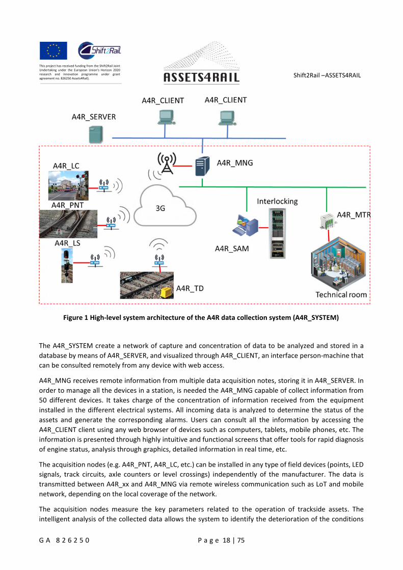
High-level system architecture
Figure 1 shows the overall high-level architecture of the A4R data collection system (A4R_SYSTEM) for oneregion. A4R_SYSTEM can be scalable for multiple interlocking systems.
Shift2Rail –ASSETS4RAIL
G A 8 2 6 2 5 0 P a g e 18 | 75
This project has received funding from the Shift2Rail JointUndertaking under the European Union’s Horizon 2020research and innovation programme under grantagreement no. 826250 Assets4Rail).
Figure 1 High-level system architecture of the A4R data collection system (A4R_SYSTEM)
The A4R_SYSTEM create a network of capture and concentration of data to be analyzed and stored in a
database by means of A4R_SERVER, and visualized through A4R_CLIENT, an interface person-machine that
can be consulted remotely from any device with web access.
A4R_MNG receives remote information from multiple data acquisition notes, storing it in A4R_SERVER. In
order to manage all the devices in a station, is needed the A4R_MNG capable of collect information from
50 different devices. It takes charge of the concentration of information received from the equipment
installed in the different electrical systems. All incoming data is analyzed to determine the status of the
assets and generate the corresponding alarms. Users can consult all the information by accessing the
A4R_CLIENT client using any web browser of devices such as computers, tablets, mobile phones, etc. The
information is presented through highly intuitive and functional screens that offer tools for rapid diagnosis
of engine status, analysis through graphics, detailed information in real time, etc.
The acquisition nodes (e.g. A4R_PNT, A4R_LC, etc.) can be installed in any type of field devices (points, LED
signals, track circuits, axle counters or level crossings) independently of the manufacturer. The data is
transmitted between A4R_xx and A4R_MNG via remote wireless communication such as LoT and mobile
network, depending on the local coverage of the network.
The acquisition nodes measure the key parameters related to the operation of trackside assets. The
intelligent analysis of the collected data allows the system to identify the deterioration of the conditions
Shift2Rail –ASSETS4RAIL
G A 8 2 6 2 5 0 P a g e 19 | 75
This project has received funding from the Shift2Rail JointUndertaking under the European Union’s Horizon 2020research and innovation programme under grantagreement no. 826250 Assets4Rail).
before a failure. This provides an important framework in which maintenance tasks can be reprogrammed
to improve performance and correct the problem before it results in a stop during service hours.
The following modules carry out the obtaining of information of the electrical devices:
A4R_LS: Module for the acquisition of information of the light signals.
A4R_PNT: Module for the acquisition of information of the point machines.
A4R_LC: Module for the acquisition of information of the level crossings.
A4R_TD: Module for the acquisition of information of the track circuits and axle counters.
The modules shall be “plug and play” devices and have a great ability to collect and transmit data in a
completely transparent way to the system to which are connected. The installation must be simple and
non-intrusive.
Apart from the trackside field elements, the centralized electronic interlocking system and the technicalrooms contain valuable information for diagnosis. A4R_ SAM collects digital data from the interlockingsystem, while A4R_ MTR from technical rooms.
Potential available data
Data from trackside field elements
To analyze the diagnosis related variables for each field element, the Eulynx protocol will be used. It givesan overview which parameters are essential for controlling and diagnosis. These parameters are obtainedby A4R_LS/ A4R_PNT/ A4R_LC/A4R_TD. For analog field devices, the parameters are measured by sensors.For digital field devices that provide data interface, the parameters can be directly read, if the protocol isunderstandable.
EULYNX is a European initiative in the area of railway signaling, with the aim of reducing the cost and
installation time of signalling equipment. Currently, there are 12 members from North and Central Europe,
with baseline 1 published in March 2017 and baseline 2 published in December 2017. The project
documents lay down a system architecture for interlocking systems, including standard interfaces for the
individual interlocking components, that can be used in any of the participating countries. The objective is
to turn interlockings into modular systems, where different parts of one interlocking can be supplied by
different manufacturers while maintaining the high safety and reliability levels required of a critical railway
safety system.
Using the Eunlynx protocol, the system obtain the following characteristics:
Use a common architecture.
With a common apportionment of functionalities.
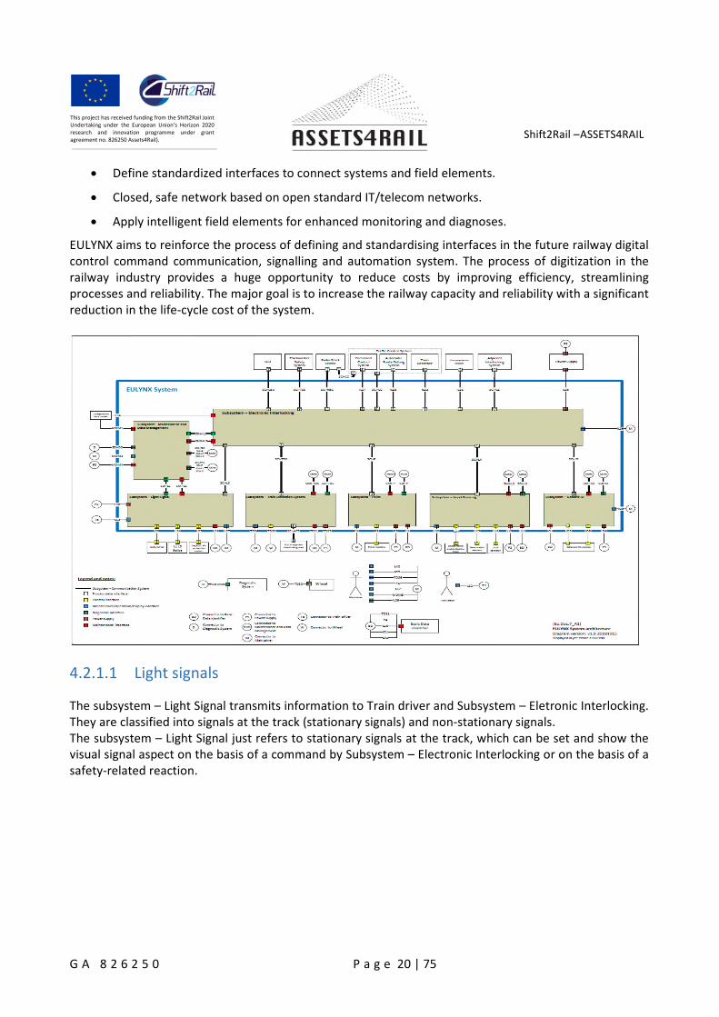
Shift2Rail –ASSETS4RAIL
G A 8 2 6 2 5 0 P a g e 20 | 75
This project has received funding from the Shift2Rail JointUndertaking under the European Union’s Horizon 2020research and innovation programme under grantagreement no. 826250 Assets4Rail).
Define standardized interfaces to connect systems and field elements.
Closed, safe network based on open standard IT/telecom networks.
Apply intelligent field elements for enhanced monitoring and diagnoses.
EULYNX aims to reinforce the process of defining and standardising interfaces in the future railway digitalcontrol command communication, signalling and automation system. The process of digitization in therailway industry provides a huge opportunity to reduce costs by improving efficiency, streamliningprocesses and reliability. The major goal is to increase the railway capacity and reliability with a significantreduction in the life-cycle cost of the system.
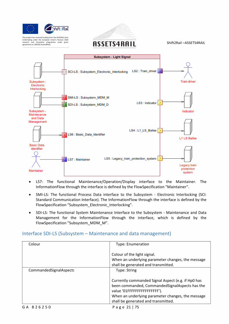
4.2.1.1 Light signals
The subsystem – Light Signal transmits information to Train driver and Subsystem – Eletronic Interlocking.They are classified into signals at the track (stationary signals) and non-stationary signals.The subsystem – Light Signal just refers to stationary signals at the track, which can be set and show thevisual signal aspect on the basis of a command by Subsystem – Electronic Interlocking or on the basis of asafety-related reaction.
Shift2Rail –ASSETS4RAIL
G A 8 2 6 2 5 0 P a g e 21 | 75
This project has received funding from the Shift2Rail JointUndertaking under the European Union’s Horizon 2020research and innovation programme under grantagreement no. 826250 Assets4Rail).
LS7: The functional Maintenance/Operation/Display interface to the Maintainer. TheInformationFlow through the interface is defined by the FlowSpecification "Maintainer".
SMI-LS: The functional Process Data interface to the Subsystem - Electronic Interlocking (SCI:Standard Communication Interface). The InformationFlow through the interface is defined by theFlowSpecification "Subsystem_Electronic_Interlocking".
SDI-LS: The functional System Maintenance Interface to the Subsystem - Maintenance and DataManagement for the InformationFlow through the interface, which is defined by theFlowSpecification "Subsystem_MDM_M".
Interface SDI-LS (Subsystem – Maintenance and data management)
Colour Type: Enumeration
Colour of the light signal.When an underlying parameter changes, the messageshall be generated and transmitted.
CommandedSignalAspects Type: String
Currently commanded Signal Aspect (e.g. if Hp0 hasbeen commanded, CommandedSignalAspects has thevalue '01FFFFFFFFFFFFFFFF').When an underlying parameter changes, the messageshall be generated and transmitted.
Shift2Rail –ASSETS4RAIL
G A 8 2 6 2 5 0 P a g e 22 | 75
This project has received funding from the Shift2Rail JointUndertaking under the European Union’s Horizon 2020research and innovation programme under grantagreement no. 826250 Assets4Rail).
CurrentSignalAspects Type: String
Currently indicated Signal Aspect (e.g. if Hp0 isindicated, CurrentSignalAspects has the value'01FFFFFFFFFFFF').When an underlying parameter changes, the messageshall be generated and transmitted.
DegenerationGrade Type: IntegerUnit: %
When an underlying parameter changes, the messageshall be generated and transmitted.
ElectronicFailure Type: Boolean
LED electronics is faulty.When an underlying parameter changes, the messageshall be generated and transmitted.
Frequency Type: FloatUnit: Hz
Momentarily measured frequency of the Legacy trainprotection system.When an underlying parameter changes, the messageshall be generated and transmitted.
Inductance Type: FloatUnit: H
Momentarily measured inductance of the Legacy trainprotection system.When an underlying parameter changes, the messageshall be generated and transmitted.
IsAuxiliaryFilamentLightFailure Type: Boolean
The auxiliary filament is faulty.When an underlying parameter changes, the messageshall be generated and transmitted.
IsContactFailure Type: Boolean
The contact of the inductive train control is faulty.When an underlying parameter changes, the messageshall be generated and transmitted.
IsDayNightModeChangeNotPossible Type: Boolean
Day/night change: possible/not possibleWhen an underlying parameter changes, the messageshall be generated and transmitted.
Shift2Rail –ASSETS4RAIL
G A 8 2 6 2 5 0 P a g e 23 | 75
This project has received funding from the Shift2Rail JointUndertaking under the European Union’s Horizon 2020research and innovation programme under grantagreement no. 826250 Assets4Rail).
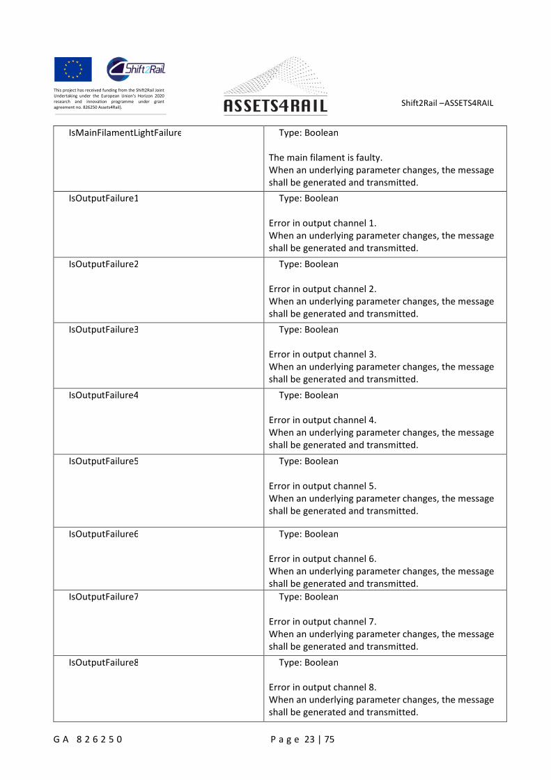
IsMainFilamentLightFailure Type: Boolean
The main filament is faulty.When an underlying parameter changes, the messageshall be generated and transmitted.
IsOutputFailure1 Type: Boolean
Error in output channel 1.When an underlying parameter changes, the messageshall be generated and transmitted.
IsOutputFailure2 Type: Boolean
Error in output channel 2.When an underlying parameter changes, the messageshall be generated and transmitted.
IsOutputFailure3 Type: Boolean
Error in output channel 3.When an underlying parameter changes, the messageshall be generated and transmitted.
IsOutputFailure4 Type: Boolean
Error in output channel 4.When an underlying parameter changes, the messageshall be generated and transmitted.
IsOutputFailure5 Type: Boolean
Error in output channel 5.When an underlying parameter changes, the messageshall be generated and transmitted.
IsOutputFailure6 Type: Boolean
Error in output channel 6.When an underlying parameter changes, the messageshall be generated and transmitted.
IsOutputFailure7 Type: Boolean
Error in output channel 7.When an underlying parameter changes, the messageshall be generated and transmitted.
IsOutputFailure8 Type: Boolean
Error in output channel 8.When an underlying parameter changes, the messageshall be generated and transmitted.
Shift2Rail –ASSETS4RAIL
G A 8 2 6 2 5 0 P a g e 24 | 75
This project has received funding from the Shift2Rail JointUndertaking under the European Union’s Horizon 2020research and innovation programme under grantagreement no. 826250 Assets4Rail).
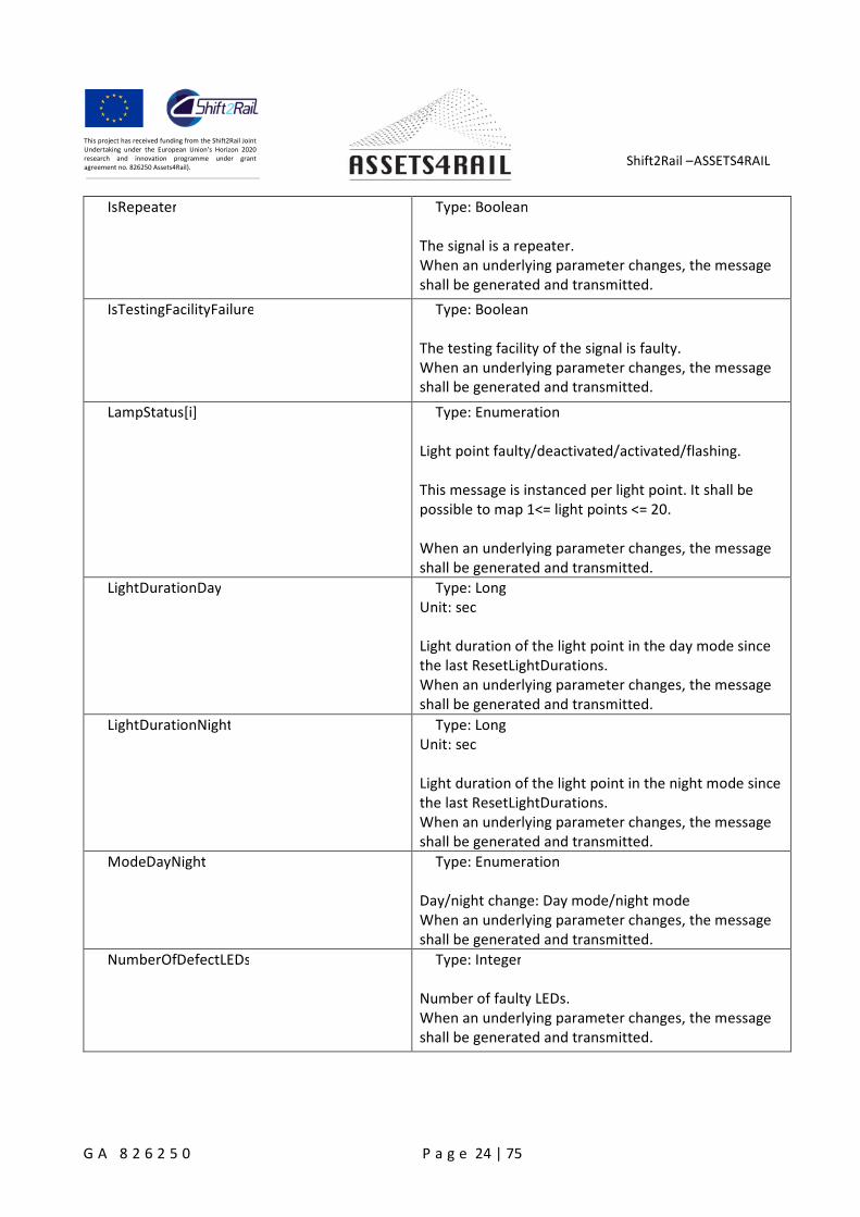
IsRepeater Type: Boolean
The signal is a repeater.When an underlying parameter changes, the messageshall be generated and transmitted.
IsTestingFacilityFailure Type: Boolean
The testing facility of the signal is faulty.When an underlying parameter changes, the messageshall be generated and transmitted.
LampStatus[i] Type: Enumeration
Light point faulty/deactivated/activated/flashing.
This message is instanced per light point. It shall bepossible to map 1<= light points <= 20.
When an underlying parameter changes, the messageshall be generated and transmitted.
LightDurationDay Type: LongUnit: sec
Light duration of the light point in the day mode sincethe last ResetLightDurations.When an underlying parameter changes, the messageshall be generated and transmitted.
LightDurationNight Type: LongUnit: sec
Light duration of the light point in the night mode sincethe last ResetLightDurations.When an underlying parameter changes, the messageshall be generated and transmitted.
ModeDayNight Type: Enumeration
Day/night change: Day mode/night modeWhen an underlying parameter changes, the messageshall be generated and transmitted.
NumberOfDefectLEDs Type: Integer
Number of faulty LEDs.When an underlying parameter changes, the messageshall be generated and transmitted.
Shift2Rail –ASSETS4RAIL
G A 8 2 6 2 5 0 P a g e 25 | 75
This project has received funding from the Shift2Rail JointUndertaking under the European Union’s Horizon 2020research and innovation programme under grantagreement no. 826250 Assets4Rail).
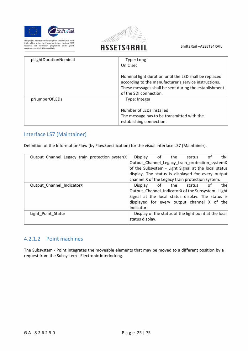
pLightDurationNominal Type: LongUnit: sec
Nominal light duration until the LED shall be replacedaccording to the manufacturer's service instructions.These messages shall be sent during the establishmentof the SDI connection.
pNumberOfLEDs Type: Integer
Number of LEDs installed.The message has to be transmitted with theestablishing connection.
Interface LS7 (Maintainer)
Definition of the InformationFlow (by FlowSpecification) for the visual interface LS7 (Maintainer).
Output_Channel_Legacy_train_protection_systemX Display of the status of theOutput_Channel_Legacy_train_protection_systemXof the Subsystem - Light Signal at the local statusdisplay. The status is displayed for every outputchannel X of the Legacy train protection system.
Output_Channel_IndicatorX Display of the status of theOutput_Channel_IndicatorX of the Subsystem - LightSignal at the local status display. The status isdisplayed for every output channel X of theIndicator.
Light_Point_Status Display of the status of the light point at the localstatus display.
4.2.1.2 Point machines
The Subsystem - Point integrates the moveable elements that may be moved to a different position by arequest from the Subsystem - Electronic Interlocking.
Shift2Rail –ASSETS4RAIL
G A 8 2 6 2 5 0 P a g e 26 | 75
This project has received funding from the Shift2Rail JointUndertaking under the European Union’s Horizon 2020research and innovation programme under grantagreement no. 826250 Assets4Rail).
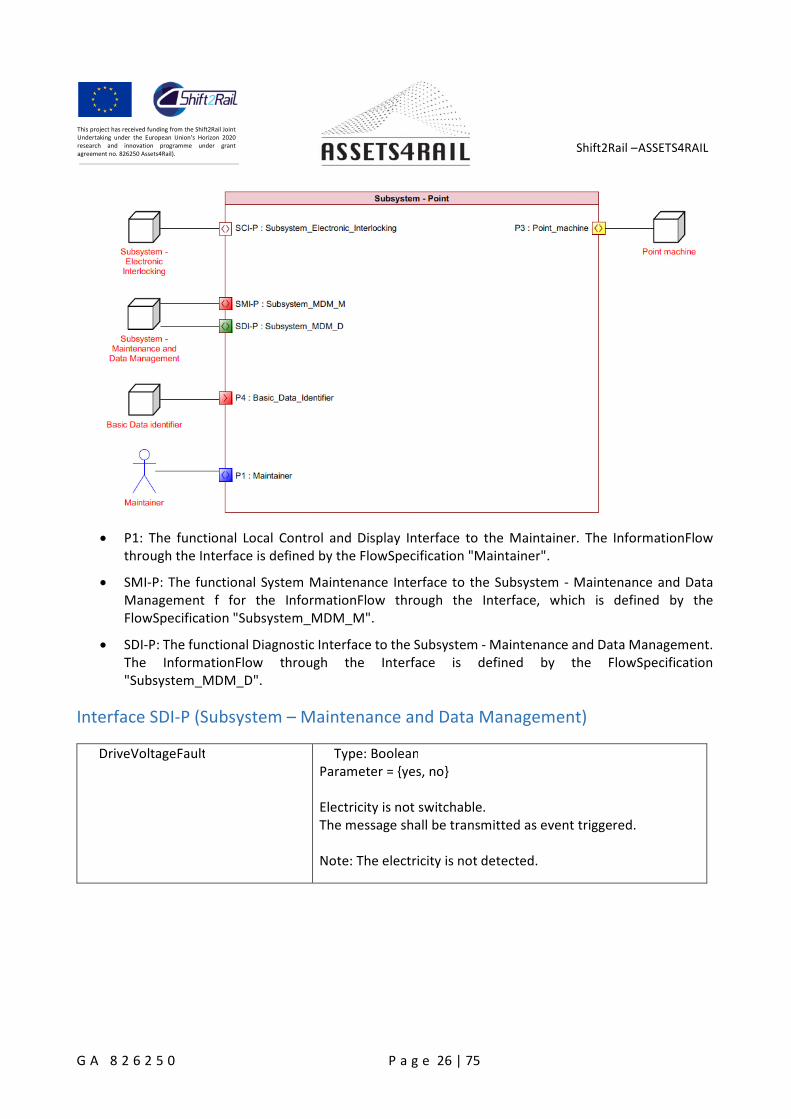
P1: The functional Local Control and Display Interface to the Maintainer. The InformationFlowthrough the Interface is defined by the FlowSpecification "Maintainer".
SMI-P: The functional System Maintenance Interface to the Subsystem - Maintenance and DataManagement f for the InformationFlow through the Interface, which is defined by theFlowSpecification "Subsystem_MDM_M".
SDI-P: The functional Diagnostic Interface to the Subsystem - Maintenance and Data Management.The InformationFlow through the Interface is defined by the FlowSpecification"Subsystem_MDM_D".
Interface SDI-P (Subsystem – Maintenance and Data Management)
DriveVoltageFault Type: BooleanParameter = {yes, no}
Electricity is not switchable.The message shall be transmitted as event triggered.
Note: The electricity is not detected.
Shift2Rail –ASSETS4RAIL
G A 8 2 6 2 5 0 P a g e 27 | 75
This project has received funding from the Shift2Rail JointUndertaking under the European Union’s Horizon 2020research and innovation programme under grantagreement no. 826250 Assets4Rail).
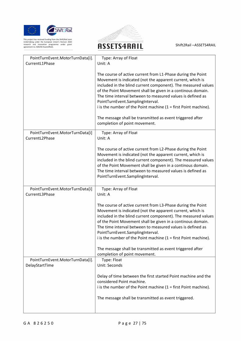
PointTurnEvent.MotorTurnData[i].CurrentL1Phase
Type: Array of FloatUnit: A
The course of active current from L1-Phase during the PointMovement is indicated (not the apparent current, which isincluded in the blind current component). The measured valuesof the Point Movement shall be given in a continous domain.The time interval between to measured values is defined asPointTurnEvent.SamplingInterval.i is the number of the Point machine (1 = first Point machine).
The message shall be transmitted as event triggered aftercompletion of point movement.
PointTurnEvent.MotorTurnData[i].CurrentL2Phase
Type: Array of FloatUnit: A
The course of active current from L2-Phase during the PointMovement is indicated (not the apparent current, which isincluded in the blind current component). The measured valuesof the Point Movement shall be given in a continous domain.The time interval between to measured values is defined asPointTurnEvent.SamplingInterval.
PointTurnEvent.MotorTurnData[i].CurrentL3Phase
Type: Array of FloatUnit: A
The course of active current from L3-Phase during the PointMovement is indicated (not the apparent current, which isincluded in the blind current component). The measured valuesof the Point Movement shall be given in a continous domain.The time interval between to measured values is defined asPointTurnEvent.SamplingInterval.i is the number of the Point machine (1 = first Point machine).
The message shall be transmitted as event triggered aftercompletion of point movement.
PointTurnEvent.MotorTurnData[i].DelayStartTime
Type: FloatUnit: Seconds
Delay of time between the first started Point machine and theconsidered Point machine.i is the number of the Point machine (1 = first Point machine).
The message shall be transmitted as event triggered.
Shift2Rail –ASSETS4RAIL
G A 8 2 6 2 5 0 P a g e 28 | 75
This project has received funding from the Shift2Rail JointUndertaking under the European Union’s Horizon 2020research and innovation programme under grantagreement no. 826250 Assets4Rail).
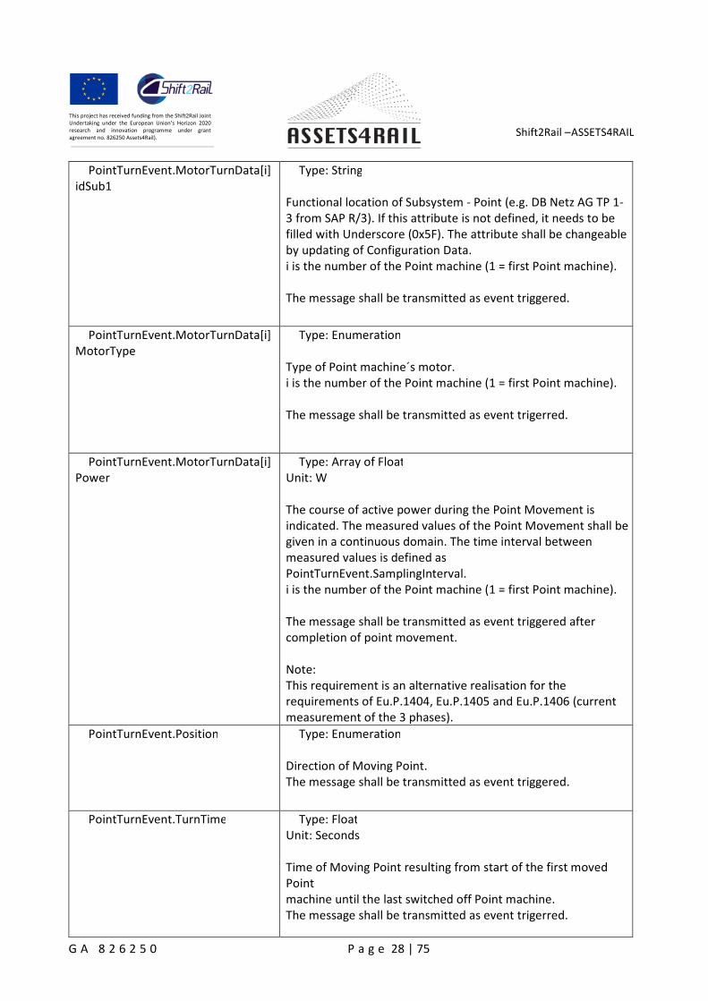
PointTurnEvent.MotorTurnData[i].idSub1
Type: String
Functional location of Subsystem - Point (e.g. DB Netz AG TP 1-3 from SAP R/3). If this attribute is not defined, it needs to befilled with Underscore (0x5F). The attribute shall be changeableby updating of Configuration Data.i is the number of the Point machine (1 = first Point machine).
The message shall be transmitted as event triggered.
PointTurnEvent.MotorTurnData[i].MotorType
Type: Enumeration
Type of Point machine´s motor.i is the number of the Point machine (1 = first Point machine).
The message shall be transmitted as event trigerred.
PointTurnEvent.MotorTurnData[i].Power
Type: Array of FloatUnit: W
The course of active power during the Point Movement isindicated. The measured values of the Point Movement shall begiven in a continuous domain. The time interval betweenmeasured values is defined asPointTurnEvent.SamplingInterval.i is the number of the Point machine (1 = first Point machine).
The message shall be transmitted as event triggered aftercompletion of point movement.
Note:This requirement is an alternative realisation for therequirements of Eu.P.1404, Eu.P.1405 and Eu.P.1406 (currentmeasurement of the 3 phases).
PointTurnEvent.Position Type: Enumeration
Direction of Moving Point.The message shall be transmitted as event triggered.
PointTurnEvent.TurnTime Type: FloatUnit: Seconds
Time of Moving Point resulting from start of the first movedPointmachine until the last switched off Point machine.The message shall be transmitted as event trigerred.
Shift2Rail –ASSETS4RAIL
G A 8 2 6 2 5 0 P a g e 29 | 75
This project has received funding from the Shift2Rail JointUndertaking under the European Union’s Horizon 2020research and innovation programme under grantagreement no. 826250 Assets4Rail).
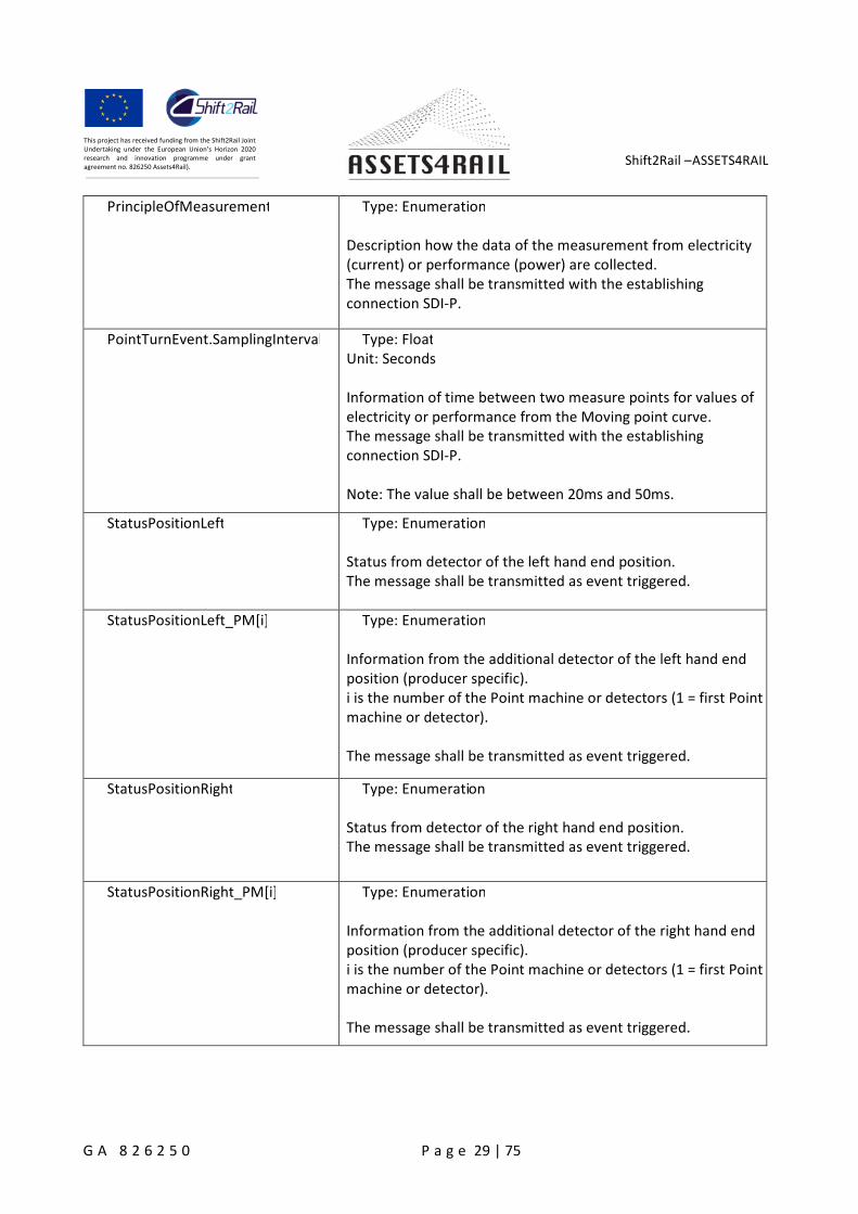
PrincipleOfMeasurement Type: Enumeration
Description how the data of the measurement from electricity(current) or performance (power) are collected.The message shall be transmitted with the establishingconnection SDI-P.
PointTurnEvent.SamplingInterval Type: FloatUnit: Seconds
Information of time between two measure points for values ofelectricity or performance from the Moving point curve.The message shall be transmitted with the establishingconnection SDI-P.
Note: The value shall be between 20ms and 50ms.
StatusPositionLeft Type: Enumeration
Status from detector of the left hand end position.The message shall be transmitted as event triggered.
StatusPositionLeft_PM[i] Type: Enumeration
Information from the additional detector of the left hand endposition (producer specific).i is the number of the Point machine or detectors (1 = first Pointmachine or detector).
The message shall be transmitted as event triggered.
StatusPositionRight Type: Enumeration
Status from detector of the right hand end position.The message shall be transmitted as event triggered.
StatusPositionRight_PM[i] Type: Enumeration
Information from the additional detector of the right hand endposition (producer specific).i is the number of the Point machine or detectors (1 = first Pointmachine or detector).
The message shall be transmitted as event triggered.
Shift2Rail –ASSETS4RAIL
G A 8 2 6 2 5 0 P a g e 30 | 75
This project has received funding from the Shift2Rail JointUndertaking under the European Union’s Horizon 2020research and innovation programme under grantagreement no. 826250 Assets4Rail).
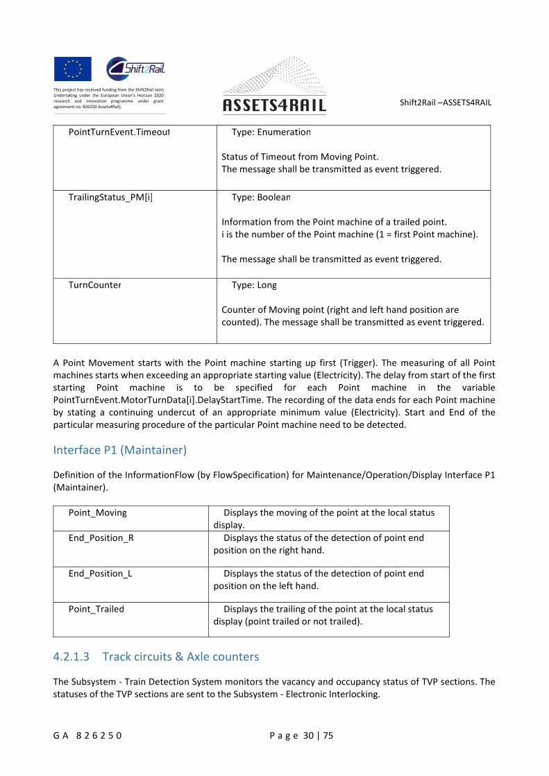
PointTurnEvent.Timeout Type: Enumeration
Status of Timeout from Moving Point.The message shall be transmitted as event triggered.
TrailingStatus_PM[i] Type: Boolean
Information from the Point machine of a trailed point.i is the number of the Point machine (1 = first Point machine).
The message shall be transmitted as event triggered.
TurnCounter Type: Long
Counter of Moving point (right and left hand position arecounted). The message shall be transmitted as event triggered.
A Point Movement starts with the Point machine starting up first (Trigger). The measuring of all Pointmachines starts when exceeding an appropriate starting value (Electricity). The delay from start of the firststarting Point machine is to be specified for each Point machine in the variablePointTurnEvent.MotorTurnData[i].DelayStartTime. The recording of the data ends for each Point machineby stating a continuing undercut of an appropriate minimum value (Electricity). Start and End of theparticular measuring procedure of the particular Point machine need to be detected.
Interface P1 (Maintainer)
Definition of the InformationFlow (by FlowSpecification) for Maintenance/Operation/Display Interface P1(Maintainer).
Point_Moving Displays the moving of the point at the local statusdisplay.
End_Position_R Displays the status of the detection of point endposition on the right hand.
End_Position_L Displays the status of the detection of point endposition on the left hand.
Point_Trailed Displays the trailing of the point at the local statusdisplay (point trailed or not trailed).
4.2.1.3 Track circuits & Axle counters
The Subsystem - Train Detection System monitors the vacancy and occupancy status of TVP sections. Thestatuses of the TVP sections are sent to the Subsystem - Electronic Interlocking.

Shift2Rail –ASSETS4RAIL
G A 8 2 6 2 5 0 P a g e 31 | 75
This project has received funding from the Shift2Rail JointUndertaking under the European Union’s Horizon 2020research and innovation programme under grantagreement no. 826250 Assets4Rail).
TDS6: The functional Local Operate and Display interface to the Maintainer. The Information Flowthrough the interface is defined by the FlowSpecification "Maintainer".
SMI-TDS: The functional System Maintenance Interface to the Subsystem - Maintenance and DataManagement for the InformationFlow through the interface, which is defined by theFlowSpecification "Subsystem_MDM_M".
SDI-TDS: The functional Diagnostic interface to the Subsystem - Maintenance and DataManagement for the InformationFlow through the interface, which is defined by theFlowSpecification "Subsystem_MDM_D".
Interface SDI-TDS (Subsystem – Maintenance and Data Management)
Subsystem_MDM_D The functional Diagnostic Interface to theSubsystem - Maintenance and DataManagement.
The InformationFlow through the Interface isdefined by the FlowSpecification"SubsystemMDMD".
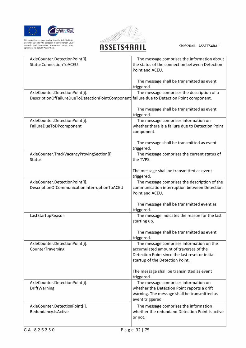
AxleCounter.DetectionPoint[i].Failure
The message comprises information onwhether the Detection Point is failed.
The message shall be transmitted as eventtriggered.
Shift2Rail –ASSETS4RAIL
G A 8 2 6 2 5 0 P a g e 32 | 75
This project has received funding from the Shift2Rail JointUndertaking under the European Union’s Horizon 2020research and innovation programme under grantagreement no. 826250 Assets4Rail).
AxleCounter.DetectionPoint[i].StatusConnectionToACEU
The message comprises the information aboutthe status of the connection between DetectionPoint and ACEU.
The message shall be transmitted as eventtriggered.
AxleCounter.DetectionPoint[i].DescriptionOfFailureDueToDetectionPointComponent
The message comprises the description of afailure due to Detection Point component.
The message shall be transmitted as eventtriggered.
AxleCounter.DetectionPoint[i].FailureDueToDPcomponent
The message comprises information onwhether there is a failure due to Detection Pointcomponent.
The message shall be transmitted as eventtriggered.
AxleCounter.TrackVacancyProvingSection[i].Status
The message comprises the current status ofthe TVPS.
The message shall be transmitted as eventtriggered.
AxleCounter.DetectionPoint[i].DescriptionOfCommunicationInterruptionToACEU
The message comprises the description of thecommunication interruption between DetectionPoint and ACEU.
The message shall be transmitted event astriggered.
LastStartupReason The message indicates the reason for the laststarting up.
The message shall be transmitted as eventtriggered.
AxleCounter.DetectionPoint[i].CounterTraversing
The message comprises information on theaccumulated amount of traverses of theDetection Point since the last reset or initialstartup of the Detection Point.
The message shall be transmitted as eventtriggered.
AxleCounter.DetectionPoint[i].DriftWarning
The message comprises information onwhether the Detection Point reports a driftwarning. The message shall be transmitted asevent triggered.
AxleCounter.DetectionPoint[i].Redundancy.IsActive
The message comprises the informationwhether the redundand Detection Point is activeor not.
Shift2Rail –ASSETS4RAIL
G A 8 2 6 2 5 0 P a g e 33 | 75
This project has received funding from the Shift2Rail JointUndertaking under the European Union’s Horizon 2020research and innovation programme under grantagreement no. 826250 Assets4Rail).
The message shall be transmitted as eventtriggered.
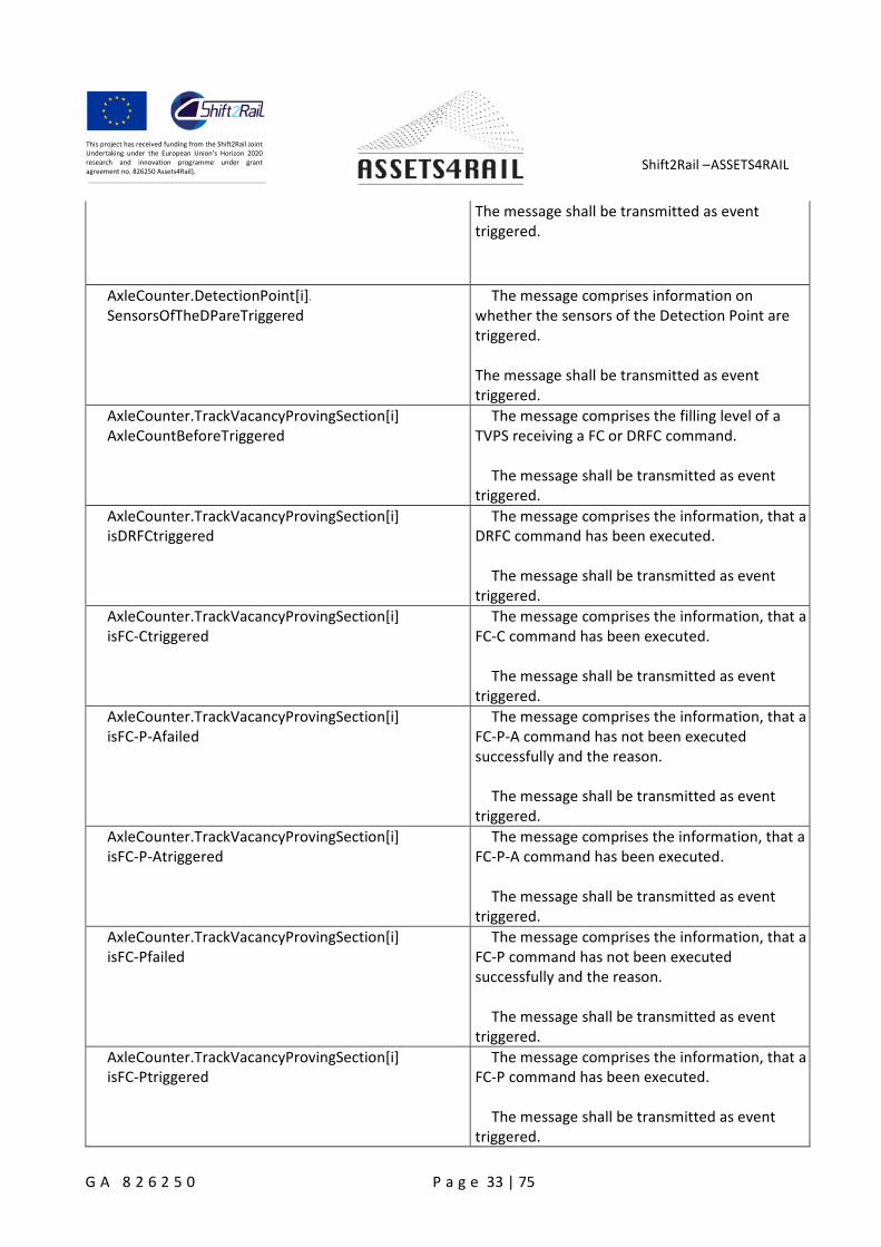
AxleCounter.DetectionPoint[i].SensorsOfTheDPareTriggered
The message comprises information onwhether the sensors of the Detection Point aretriggered.
The message shall be transmitted as eventtriggered.
AxleCounter.TrackVacancyProvingSection[i].AxleCountBeforeTriggered
The message comprises the filling level of aTVPS receiving a FC or DRFC command.
The message shall be transmitted as eventtriggered.
AxleCounter.TrackVacancyProvingSection[i].isDRFCtriggered
The message comprises the information, that aDRFC command has been executed.
The message shall be transmitted as eventtriggered.
AxleCounter.TrackVacancyProvingSection[i].isFC-Ctriggered
The message comprises the information, that aFC-C command has been executed.
The message shall be transmitted as eventtriggered.
AxleCounter.TrackVacancyProvingSection[i].isFC-P-Afailed
The message comprises the information, that aFC-P-A command has not been executedsuccessfully and the reason.
The message shall be transmitted as eventtriggered.
AxleCounter.TrackVacancyProvingSection[i].isFC-P-Atriggered
The message comprises the information, that aFC-P-A command has been executed.
The message shall be transmitted as eventtriggered.
AxleCounter.TrackVacancyProvingSection[i].isFC-Pfailed
The message comprises the information, that aFC-P command has not been executedsuccessfully and the reason.
The message shall be transmitted as eventtriggered.
AxleCounter.TrackVacancyProvingSection[i].isFC-Ptriggered
The message comprises the information, that aFC-P command has been executed.
The message shall be transmitted as eventtriggered.
Shift2Rail –ASSETS4RAIL
G A 8 2 6 2 5 0 P a g e 34 | 75
This project has received funding from the Shift2Rail JointUndertaking under the European Union’s Horizon 2020research and innovation programme under grantagreement no. 826250 Assets4Rail).
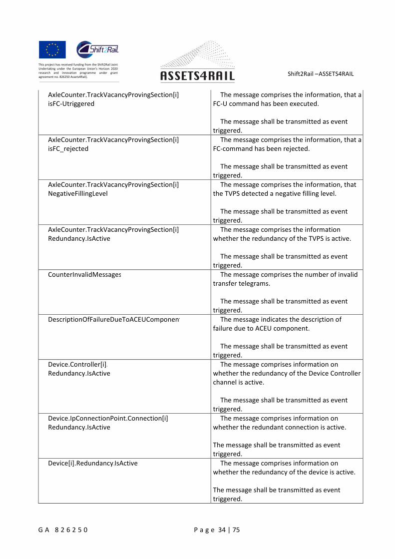
AxleCounter.TrackVacancyProvingSection[i].isFC-Utriggered
The message comprises the information, that aFC-U command has been executed.
The message shall be transmitted as eventtriggered.
AxleCounter.TrackVacancyProvingSection[i].isFC_rejected
The message comprises the information, that aFC-command has been rejected.
The message shall be transmitted as eventtriggered.
AxleCounter.TrackVacancyProvingSection[i].NegativeFillingLevel
The message comprises the information, thatthe TVPS detected a negative filling level.
The message shall be transmitted as eventtriggered.
AxleCounter.TrackVacancyProvingSection[i].Redundancy.IsActive
The message comprises the informationwhether the redundancy of the TVPS is active.
The message shall be transmitted as eventtriggered.
CounterInvalidMessages The message comprises the number of invalidtransfer telegrams.
The message shall be transmitted as eventtriggered.
DescriptionOfFailureDueToACEUComponent The message indicates the description offailure due to ACEU component.
The message shall be transmitted as eventtriggered.
Device.Controller[i].Redundancy.IsActive
The message comprises information onwhether the redundancy of the Device Controllerchannel is active.
The message shall be transmitted as eventtriggered.
Device.IpConnectionPoint.Connection[i].Redundancy.IsActive
The message comprises information onwhether the redundant connection is active.
The message shall be transmitted as eventtriggered.
Device[i].Redundancy.IsActive The message comprises information onwhether the redundancy of the device is active.
The message shall be transmitted as eventtriggered.
Shift2Rail –ASSETS4RAIL
G A 8 2 6 2 5 0 P a g e 35 | 75
This project has received funding from the Shift2Rail JointUndertaking under the European Union’s Horizon 2020research and innovation programme under grantagreement no. 826250 Assets4Rail).
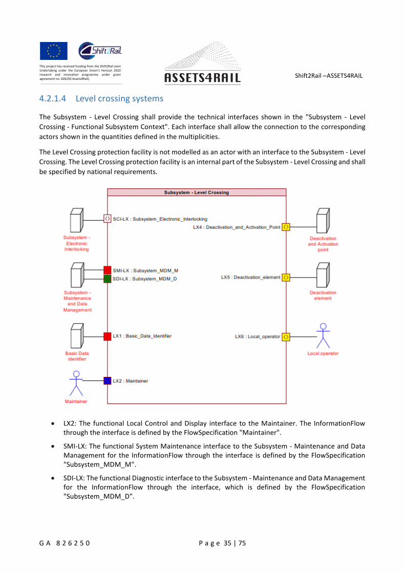
4.2.1.4 Level crossing systems
The Subsystem - Level Crossing shall provide the technical interfaces shown in the "Subsystem - Level
Crossing - Functional Subsystem Context". Each interface shall allow the connection to the corresponding
actors shown in the quantities defined in the multiplicities.
The Level Crossing protection facility is not modelled as an actor with an interface to the Subsystem - Level
Crossing. The Level Crossing protection facility is an internal part of the Subsystem - Level Crossing and shall
be specified by national requirements.
LX2: The functional Local Control and Display interface to the Maintainer. The InformationFlowthrough the interface is defined by the FlowSpecification "Maintainer".
SMI-LX: The functional System Maintenance interface to the Subsystem - Maintenance and DataManagement for the InformationFlow through the interface is defined by the FlowSpecification"Subsystem_MDM_M".
SDI-LX: The functional Diagnostic interface to the Subsystem - Maintenance and Data Managementfor the InformationFlow through the interface, which is defined by the FlowSpecification"Subsystem_MDM_D".
Shift2Rail –ASSETS4RAIL
G A 8 2 6 2 5 0 P a g e 36 | 75
This project has received funding from the Shift2Rail JointUndertaking under the European Union’s Horizon 2020research and innovation programme under grantagreement no. 826250 Assets4Rail).
Interface SDI-LX (Subsystem – Maintenance and Data Management)
LevelCrossing.LevelCrossingProtectionFacility.Barrier[i].Status
The message comprises the status of adetermined Barrier.
The message shall be transmitted as eventtriggered.
LevelCrossing.LevelCrossingProtectionFacility.ObstacleDetector[i].Obstacle
The message comprises the detection of anObstacle of a determined Obstacle detector.
The message shall be transmitted as eventtriggered.
LevelCrossing.LevelCrossingProtectionFacility.ObstacleDetector[i].Status
The message comprises the critical or non- criticalfault of a determined Obstacle detector.
The message shall be transmitted as eventtriggered.
LevelCrossing.LevelCrossingProtectionFacility.RoadLight[i].Lamps[j].Status
The message comprises the status of adetermined Road Light for the road protection iswhether switched on or off.
The message shall be transmitted as eventtriggered.
LevelCrossing.LevelCrossingProtectionFacility.BarrierMachineMotor.Control
The message comprises the status of the BarrierMachine Motor.
The message shall be transmitted as eventtriggered.
LevelCrossing.LevelCrossingProtectionFacility.BarrierMachineMotor.Current
The message comprises the status of the BarrierMachine Motor for moving the Barrier.
The message shall be transmitted as eventtriggered.
LevelCrossing.LevelCrossingProtectionFacility.BarrierMovementEvent.SamplingInterval
The message comprises the status of the BarrierMovement Event.
The message shall be transmitted as eventtriggered.
Shift2Rail –ASSETS4RAIL
G A 8 2 6 2 5 0 P a g e 37 | 75
This project has received funding from the Shift2Rail JointUndertaking under the European Union’s Horizon 2020research and innovation programme under grantagreement no. 826250 Assets4Rail).
LevelCrossing.LevelCrossingProtectionFacility.BarrierMachinePedestalDoorsClosed
The message comprises the status of the BarrierMachine Pedestal Doors Closed.
The message shall be transmitted as eventtriggered.
LevelCrossing.PrimaryPowerSource.Status The message comprises whether the primarypower source faild.
The message shall be transmitted as eventtriggered.
LevelCrossing.PowerSupply The message comprises the status of the Powersupply.
The message shall be transmitted as eventtriggered.
LevelCrossing.ObservationFacility[i].Status The message comprises whether the facility toobserve the Level Crossing is switched on.
The message shall be transmitted as eventtriggered.
LevelCrossing.FloodLight[i].Status The message comprises whether theFlood Lightis switched on.
The message shall be transmitted as eventtriggered.
LevelCrossing.AutoMovement.Status The message comprises the status of the AutoRaise.
The message shall be transmitted as eventtriggered.
Data from interlocking systems
Nowadays all the electronic interlockings have a Maintenance Support System (SAM) that allows scheduled
maintenance to be carried out.
The SAM equipment consists of a rack mounted PC that acts as a central data store for the system. It logs
all messages that are passed between the various part of the interlocking system. It also stores the
configuration for each of the processor units. This is used to check that each unit is correctly configured
and to update the configuration if necessary. It also allows the technicians access to the all logged data and
allows controls to be applied.
Shift2Rail –ASSETS4RAIL
G A 8 2 6 2 5 0 P a g e 38 | 75
This project has received funding from the Shift2Rail JointUndertaking under the European Union’s Horizon 2020research and innovation programme under grantagreement no. 826250 Assets4Rail).
The problem is that each manufacturer has its own protocol between interlocking and SAM, and its own
name of alarms and data management. There should be SAM Translator (SAMT) that obtain all the debug
log files that are generated by the SAM, and with an XML unified model, translate to a common format,
independently of the technology of the SAM and interlocking. The translated log files are sent to A4R_MNG
in a specific format like the defined in the SysLog protocol and processed along with the data obtained from
the field elements. The connection between the SAMs and the A4R_MNG is done through the Ethernet
network, using the TCP/IP protocol.
4.2.2.1 Log files
The interlocking systems usually log the actions relating to the field elements. The main data sources used
in this thesis are the log files produced by interlocking systems. Each field elements has its own logical entity
that pulls and pushes information to the interlocking system. Each operation of a field element gets an
operation time stamp in the server and stored in the log files.
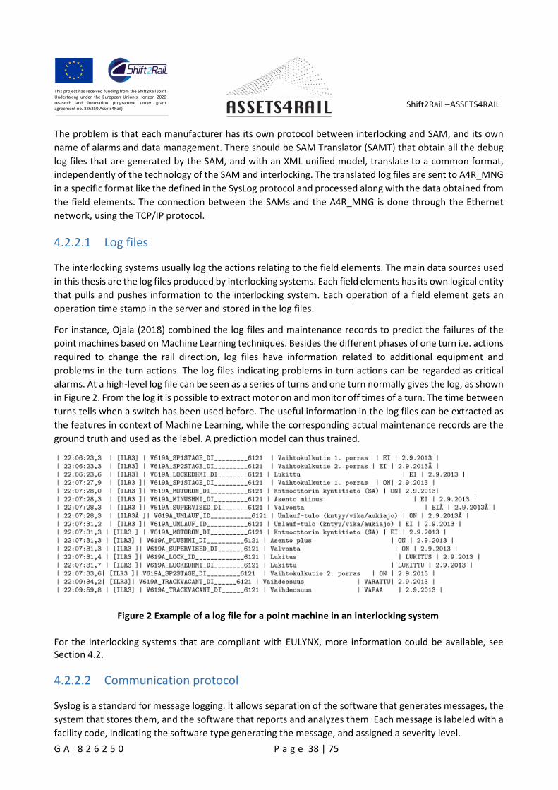
For instance, Ojala (2018) combined the log files and maintenance records to predict the failures of the
point machines based on Machine Learning techniques. Besides the different phases of one turn i.e. actions
required to change the rail direction, log files have information related to additional equipment and
problems in the turn actions. The log files indicating problems in turn actions can be regarded as critical
alarms. At a high-level log file can be seen as a series of turns and one turn normally gives the log, as shown
in Figure 2. From the log it is possible to extract motor on and monitor off times of a turn. The time between
turns tells when a switch has been used before. The useful information in the log files can be extracted as
the features in context of Machine Learning, while the corresponding actual maintenance records are the
ground truth and used as the label. A prediction model can thus trained.
Figure 2 Example of a log file for a point machine in an interlocking system
For the interlocking systems that are compliant with EULYNX, more information could be available, seeSection 4.2.
4.2.2.2 Communication protocol
Syslog is a standard for message logging. It allows separation of the software that generates messages, the
system that stores them, and the software that reports and analyzes them. Each message is labeled with a
facility code, indicating the software type generating the message, and assigned a severity level.
Shift2Rail –ASSETS4RAIL
G A 8 2 6 2 5 0 P a g e 39 | 75
This project has received funding from the Shift2Rail JointUndertaking under the European Union’s Horizon 2020research and innovation programme under grantagreement no. 826250 Assets4Rail).
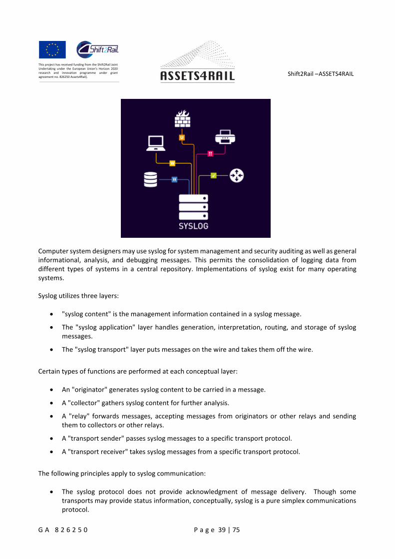
Computer system designers may use syslog for system management and security auditing as well as generalinformational, analysis, and debugging messages. This permits the consolidation of logging data fromdifferent types of systems in a central repository. Implementations of syslog exist for many operatingsystems.
Syslog utilizes three layers:
"syslog content" is the management information contained in a syslog message.
The "syslog application" layer handles generation, interpretation, routing, and storage of syslogmessages.
The "syslog transport" layer puts messages on the wire and takes them off the wire.
Certain types of functions are performed at each conceptual layer:
An "originator" generates syslog content to be carried in a message.
A "collector" gathers syslog content for further analysis.
A "relay" forwards messages, accepting messages from originators or other relays and sendingthem to collectors or other relays.
A "transport sender" passes syslog messages to a specific transport protocol.
A "transport receiver" takes syslog messages from a specific transport protocol.
The following principles apply to syslog communication:
The syslog protocol does not provide acknowledgment of message delivery. Though sometransports may provide status information, conceptually, syslog is a pure simplex communicationsprotocol.
Shift2Rail –ASSETS4RAIL
G A 8 2 6 2 5 0 P a g e 40 | 75
This project has received funding from the Shift2Rail JointUndertaking under the European Union’s Horizon 2020research and innovation programme under grantagreement no. 826250 Assets4Rail).
Originators and relays may be configured to send the same message to multiple collectors andrelays.
Originator, relay, and collector functionality may reside on the same system.
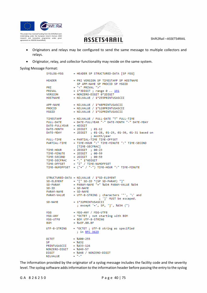
Syslog Message Format:
The information provided by the originator of a syslog message includes the facility code and the severity
level. The syslog software adds information to the information header before passing the entry to the syslog
Shift2Rail –ASSETS4RAIL
G A 8 2 6 2 5 0 P a g e 41 | 75
This project has received funding from the Shift2Rail JointUndertaking under the European Union’s Horizon 2020research and innovation programme under grantagreement no. 826250 Assets4Rail).
receiver. Such components include an originator process ID, a timestamp, and the hostname or IP address
of the device.
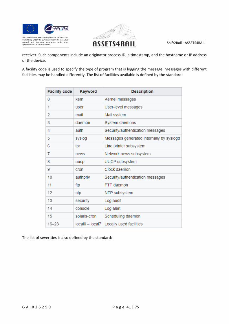
A facility code is used to specify the type of program that is logging the message. Messages with different
facilities may be handled differently. The list of facilities available is defined by the standard:
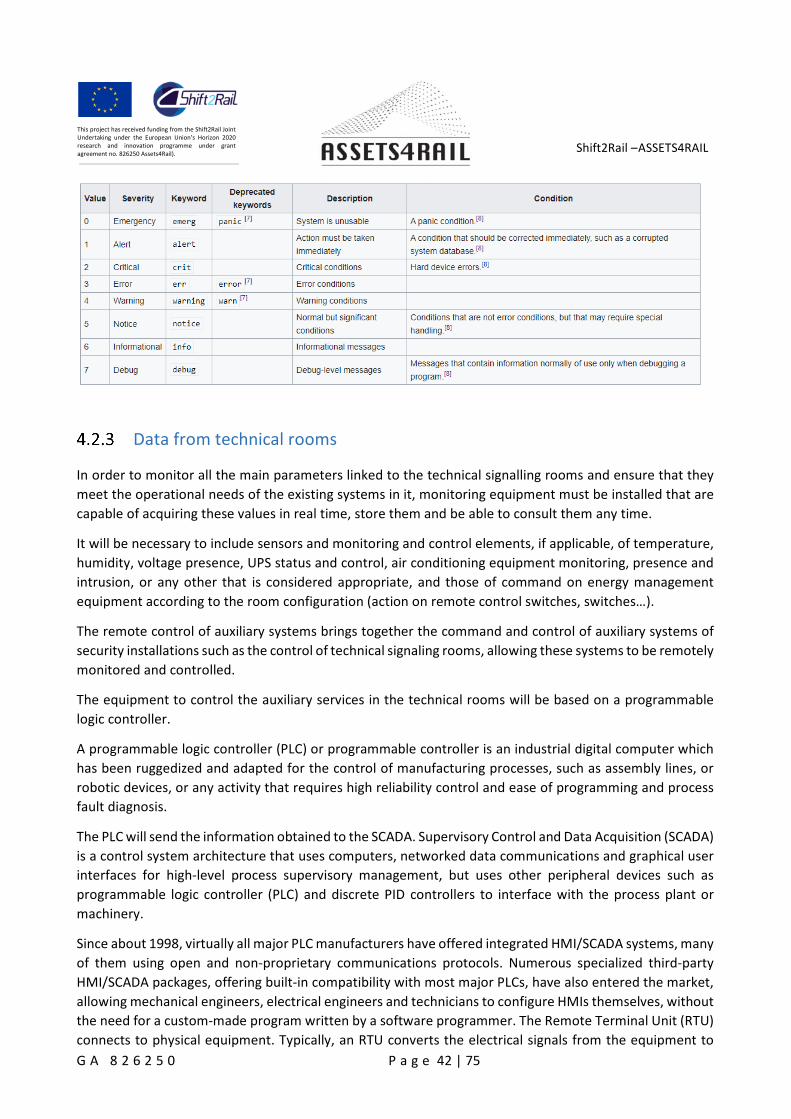
The list of severities is also defined by the standard:
Shift2Rail –ASSETS4RAIL
G A 8 2 6 2 5 0 P a g e 42 | 75
This project has received funding from the Shift2Rail JointUndertaking under the European Union’s Horizon 2020research and innovation programme under grantagreement no. 826250 Assets4Rail).
Data from technical rooms
In order to monitor all the main parameters linked to the technical signalling rooms and ensure that they
meet the operational needs of the existing systems in it, monitoring equipment must be installed that are
capable of acquiring these values in real time, store them and be able to consult them any time.
It will be necessary to include sensors and monitoring and control elements, if applicable, of temperature,
humidity, voltage presence, UPS status and control, air conditioning equipment monitoring, presence and
intrusion, or any other that is considered appropriate, and those of command on energy management
equipment according to the room configuration (action on remote control switches, switches…).
The remote control of auxiliary systems brings together the command and control of auxiliary systems of
security installations such as the control of technical signaling rooms, allowing these systems to be remotely
monitored and controlled.
The equipment to control the auxiliary services in the technical rooms will be based on a programmable
logic controller.
A programmable logic controller (PLC) or programmable controller is an industrial digital computer which
has been ruggedized and adapted for the control of manufacturing processes, such as assembly lines, or
robotic devices, or any activity that requires high reliability control and ease of programming and process
fault diagnosis.
The PLC will send the information obtained to the SCADA. Supervisory Control and Data Acquisition (SCADA)
is a control system architecture that uses computers, networked data communications and graphical user
interfaces for high-level process supervisory management, but uses other peripheral devices such as
programmable logic controller (PLC) and discrete PID controllers to interface with the process plant or
machinery.
Since about 1998, virtually all major PLC manufacturers have offered integrated HMI/SCADA systems, many
of them using open and non-proprietary communications protocols. Numerous specialized third-party
HMI/SCADA packages, offering built-in compatibility with most major PLCs, have also entered the market,
allowing mechanical engineers, electrical engineers and technicians to configure HMIs themselves, without
the need for a custom-made program written by a software programmer. The Remote Terminal Unit (RTU)
connects to physical equipment. Typically, an RTU converts the electrical signals from the equipment to
Shift2Rail –ASSETS4RAIL
G A 8 2 6 2 5 0 P a g e 43 | 75
This project has received funding from the Shift2Rail JointUndertaking under the European Union’s Horizon 2020research and innovation programme under grantagreement no. 826250 Assets4Rail).
digital values such as the open/closed status from a switch or a valve, or measurements such as pressure,
flow, voltage or current.
The next requirements are used by ADIF to monitoring the technical rooms. It can be used and example.
4.2.3.1 Cabinet
The cabinet houses the auxiliary components of the PLC:
Source power.
Magnetothermal protection.
Signal conditioners.
Digital output relays.
Wiring connection. Input and output signals.
The types of signals to be handled by the PLC will be the following:
24 Vdc Digital inputs.
Digital outputs based on relay 2A.
Analog inputs 0 -10 Vdc
It can handle inputs/outputs according the needs of the technical room.
The automaton’s memory will be enough to handle the inputs and outputs of the technical rooms.
The PLC can be powered with 230 Vac voltage.
The independent analog input modules of the PLC to be incorporated will have a resolution o 13 bits (12signed) being configurable:
Voltage: 10V, 5V, 2.5V
Current: 0-20mA, 4-20mA.
The signal conditioners will have as characteristics:
Universal isolator of the true RMS of an AC/DC current.
Admission of continuous and alternating voltage distorted, rectified and with harmonics withfrequencies up to 800 Hz.
Output signal configurable in intensitiy (0-20 mA, 4-20 mA) or voltage (0-5 V, 0-10 V).
They can be powered at 24 Vdc or 230 Vac, with a wide range in both cases.
There will be isolation between the input and the output, and between both and the power circuit.
Shift2Rail –ASSETS4RAIL
G A 8 2 6 2 5 0 P a g e 44 | 75
This project has received funding from the Shift2Rail JointUndertaking under the European Union’s Horizon 2020research and innovation programme under grantagreement no. 826250 Assets4Rail).
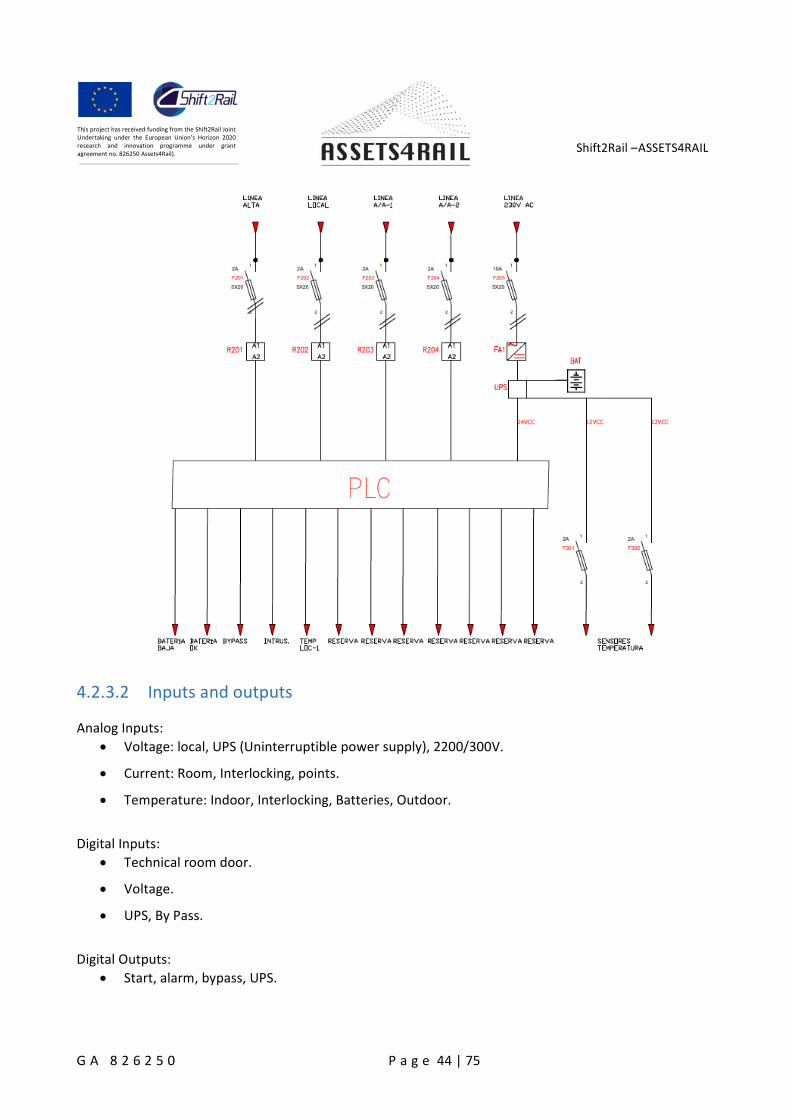
4.2.3.2 Inputs and outputs
Analog Inputs:
Voltage: local, UPS (Uninterruptible power supply), 2200/300V.
Current: Room, Interlocking, points.
Temperature: Indoor, Interlocking, Batteries, Outdoor.
Digital Inputs:
Technical room door.
Voltage.
UPS, By Pass.
Digital Outputs:
Start, alarm, bypass, UPS.
Shift2Rail –ASSETS4RAIL
G A 8 2 6 2 5 0 P a g e 45 | 75
This project has received funding from the Shift2Rail JointUndertaking under the European Union’s Horizon 2020research and innovation programme under grantagreement no. 826250 Assets4Rail).
4.2.3.3 Sensors
Temperature sounding line.
Current sounding line.
Split-core current transformer with built-in converter, capable of measuring up to 100 A, AC, with a
converted output of 4 to 20 mA DC, fully compatible with the PLC without the need for any measurement
adjustment.
Split-core allows installation without power outages and without complex disconnections of existing wiring.
The transformer is only connected to the equipment by means of 2 wires: one of them provides the power
supply and other returns the 4/20 mA signal.
Open doors detectors.
Normally closed magnetic contact (maximum 100mA at 28 Vdc) and length 45 mm.
4.2.3.4 UPS connection
The connection with the IPV is made through their potential free contacts. These contacts connect directlyto the PLC digital inputs.The remote orders can be:
switched to by-pass
remote start.
The connection to the central management server is done through the Ethernet network, using the TCP/IPprotocol.
The PLC provides SCADA with a set of addresses in its memory that it can consult and, in some cases, modify:
Analog inputs, type 32 bits.
Digital inputs, Boolean type.
The ADIF (Spain) company is using the protocol OPC (OLE for Process Control) to connect the SCADA to thePLC.
4.2.3.5 Communication protocol
SCADA systems have traditionally used combinations of radio and direct wired connections, although
SONET/SDH is also frequently used for large systems such as railways and power stations. The remote
management or monitoring function of a SCADA system is often referred to as telemetry. Some users want
SCADA data to travel over their pre-established corporate networks or to share the network with other
applications. The legacy of the early low-bandwidth protocols remains, though.
SCADA protocols are designed to be very compact. Many are designed to send information only when the
master station polls the RTU. Typical legacy SCADA protocols include Modbus RTU, RP-570, Profibus and
Conitel. These communication protocols, with the exception of Modbus (Modbus has been made open by
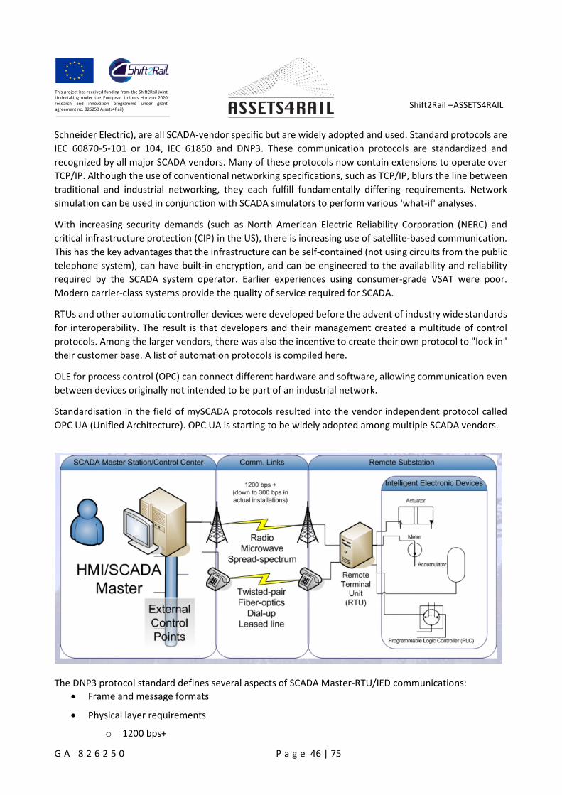
Shift2Rail –ASSETS4RAIL
G A 8 2 6 2 5 0 P a g e 46 | 75
This project has received funding from the Shift2Rail JointUndertaking under the European Union’s Horizon 2020research and innovation programme under grantagreement no. 826250 Assets4Rail).
Schneider Electric), are all SCADA-vendor specific but are widely adopted and used. Standard protocols are
IEC 60870-5-101 or 104, IEC 61850 and DNP3. These communication protocols are standardized and
recognized by all major SCADA vendors. Many of these protocols now contain extensions to operate over
TCP/IP. Although the use of conventional networking specifications, such as TCP/IP, blurs the line between
traditional and industrial networking, they each fulfill fundamentally differing requirements. Network
simulation can be used in conjunction with SCADA simulators to perform various 'what-if' analyses.
With increasing security demands (such as North American Electric Reliability Corporation (NERC) and
critical infrastructure protection (CIP) in the US), there is increasing use of satellite-based communication.
This has the key advantages that the infrastructure can be self-contained (not using circuits from the public
telephone system), can have built-in encryption, and can be engineered to the availability and reliability
required by the SCADA system operator. Earlier experiences using consumer-grade VSAT were poor.
Modern carrier-class systems provide the quality of service required for SCADA.
RTUs and other automatic controller devices were developed before the advent of industry wide standards
for interoperability. The result is that developers and their management created a multitude of control
protocols. Among the larger vendors, there was also the incentive to create their own protocol to "lock in"
their customer base. A list of automation protocols is compiled here.
OLE for process control (OPC) can connect different hardware and software, allowing communication even
between devices originally not intended to be part of an industrial network.
Standardisation in the field of mySCADA protocols resulted into the vendor independent protocol called
OPC UA (Unified Architecture). OPC UA is starting to be widely adopted among multiple SCADA vendors.
The DNP3 protocol standard defines several aspects of SCADA Master-RTU/IED communications:
Frame and message formats
Physical layer requirements
o 1200 bps+
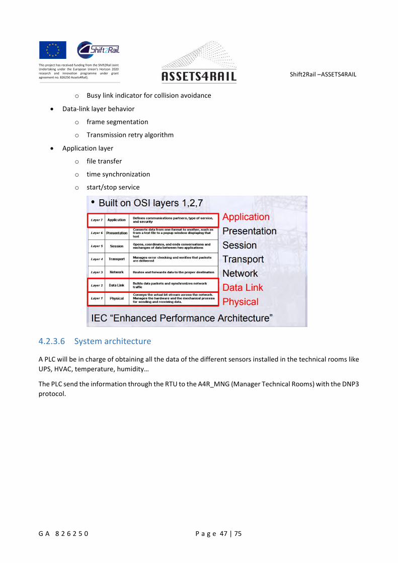
Shift2Rail –ASSETS4RAIL
G A 8 2 6 2 5 0 P a g e 47 | 75
This project has received funding from the Shift2Rail JointUndertaking under the European Union’s Horizon 2020research and innovation programme under grantagreement no. 826250 Assets4Rail).
o Busy link indicator for collision avoidance
Data-link layer behavior
o frame segmentation
o Transmission retry algorithm
Application layer
o file transfer
o time synchronization
o start/stop service
4.2.3.6 System architecture
A PLC will be in charge of obtaining all the data of the different sensors installed in the technical rooms like
UPS, HVAC, temperature, humidity…
The PLC send the information through the RTU to the A4R_MNG (Manager Technical Rooms) with the DNP3
protocol.
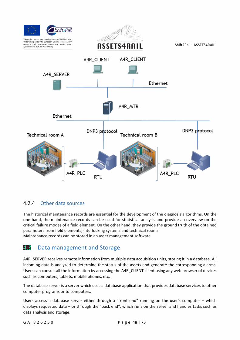
Shift2Rail –ASSETS4RAIL
G A 8 2 6 2 5 0 P a g e 48 | 75
This project has received funding from the Shift2Rail JointUndertaking under the European Union’s Horizon 2020research and innovation programme under grantagreement no. 826250 Assets4Rail).
Other data sources
The historical maintenance records are essential for the development of the diagnosis algorithms. On theone hand, the maintenance records can be used for statistical analysis and provide an overview on thecritical failure modes of a field element. On the other hand, they provide the ground truth of the obtainedparameters from field elements, interlocking systems and technical rooms.Maintenance records can be stored in an asset management software
Data management and Storage
A4R_SERVER receives remote information from multiple data acquisition units, storing it in a database. All
incoming data is analyzed to determine the status of the assets and generate the corresponding alarms.
Users can consult all the information by accessing the A4R_CLIENT client using any web browser of devices
such as computers, tablets, mobile phones, etc.
The database server is a server which uses a database application that provides database services to other
computer programs or to computers.
Users access a database server either through a "front end" running on the user's computer – which
displays requested data – or through the "back end", which runs on the server and handles tasks such as
data analysis and storage.
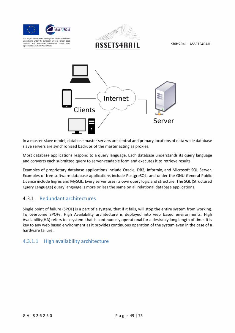
Shift2Rail –ASSETS4RAIL
G A 8 2 6 2 5 0 P a g e 49 | 75
This project has received funding from the Shift2Rail JointUndertaking under the European Union’s Horizon 2020research and innovation programme under grantagreement no. 826250 Assets4Rail).
In a master-slave model, database master servers are central and primary locations of data while database
slave servers are synchronized backups of the master acting as proxies.
Most database applications respond to a query language. Each database understands its query language
and converts each submitted query to server-readable form and executes it to retrieve results.
Examples of proprietary database applications include Oracle, DB2, Informix, and Microsoft SQL Server.
Examples of free software database applications include PostgreSQL; and under the GNU General Public
Licence include Ingres and MySQL. Every server uses its own query logic and structure. The SQL (Structured
Query Language) query language is more or less the same on all relational database applications.
Redundant architectures
Single point of failure (SPOF) is a part of a system, that if it fails, will stop the entire system from working.To overcome SPOFs, High Availability architecture is deployed into web based environments. HighAvailability(HA) refers to a system that is continuously operational for a desirably long length of time. It iskey to any web based environment as it provides continuous operation of the system even in the case of ahardware failure.
4.3.1.1 High availability architecture
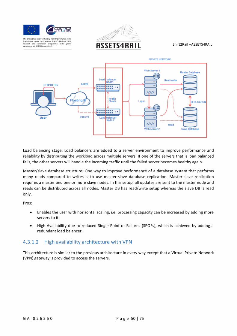
Shift2Rail –ASSETS4RAIL
G A 8 2 6 2 5 0 P a g e 50 | 75
This project has received funding from the Shift2Rail JointUndertaking under the European Union’s Horizon 2020research and innovation programme under grantagreement no. 826250 Assets4Rail).
Load balancing stage: Load balancers are added to a server environment to improve performance and
reliability by distributing the workload across multiple servers. If one of the servers that is load balanced
fails, the other servers will handle the incoming traffic until the failed server becomes healthy again.
Master/slave database structure: One way to improve performance of a database system that performs
many reads compared to writes is to use master-slave database replication. Master-slave replication
requires a master and one or more slave nodes. In this setup, all updates are sent to the master node and
reads can be distributed across all nodes. Master DB has read/write setup whereas the slave DB is read
only.
Pros:
Enables the user with horizontal scaling, i.e. processing capacity can be increased by adding moreservers to it.
High Availability due to reduced Single Point of Failures (SPOFs), which is achieved by adding aredundant load balancer.
4.3.1.2 High availability architecture with VPN
This architecture is similar to the previous architecture in every way except that a Virtual Private Network(VPN) gateway is provided to access the servers.
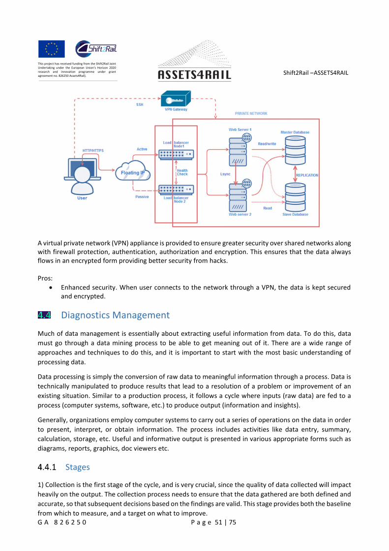
Shift2Rail –ASSETS4RAIL
G A 8 2 6 2 5 0 P a g e 51 | 75
This project has received funding from the Shift2Rail JointUndertaking under the European Union’s Horizon 2020research and innovation programme under grantagreement no. 826250 Assets4Rail).
A virtual private network (VPN) appliance is provided to ensure greater security over shared networks alongwith firewall protection, authentication, authorization and encryption. This ensures that the data alwaysflows in an encrypted form providing better security from hacks.
Pros:
Enhanced security. When user connects to the network through a VPN, the data is kept securedand encrypted.
Diagnostics Management
Much of data management is essentially about extracting useful information from data. To do this, data
must go through a data mining process to be able to get meaning out of it. There are a wide range of
approaches and techniques to do this, and it is important to start with the most basic understanding of
processing data.
Data processing is simply the conversion of raw data to meaningful information through a process. Data is
technically manipulated to produce results that lead to a resolution of a problem or improvement of an
existing situation. Similar to a production process, it follows a cycle where inputs (raw data) are fed to a
process (computer systems, software, etc.) to produce output (information and insights).
Generally, organizations employ computer systems to carry out a series of operations on the data in order
to present, interpret, or obtain information. The process includes activities like data entry, summary,
calculation, storage, etc. Useful and informative output is presented in various appropriate forms such as
diagrams, reports, graphics, doc viewers etc.
Stages
1) Collection is the first stage of the cycle, and is very crucial, since the quality of data collected will impact
heavily on the output. The collection process needs to ensure that the data gathered are both defined and
accurate, so that subsequent decisions based on the findings are valid. This stage provides both the baseline
from which to measure, and a target on what to improve.
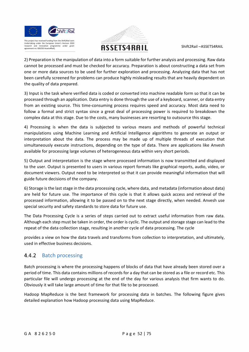
Shift2Rail –ASSETS4RAIL
G A 8 2 6 2 5 0 P a g e 52 | 75
This project has received funding from the Shift2Rail JointUndertaking under the European Union’s Horizon 2020research and innovation programme under grantagreement no. 826250 Assets4Rail).
2) Preparation is the manipulation of data into a form suitable for further analysis and processing. Raw data
cannot be processed and must be checked for accuracy. Preparation is about constructing a data set from
one or more data sources to be used for further exploration and processing. Analyzing data that has not
been carefully screened for problems can produce highly misleading results that are heavily dependent on
the quality of data prepared.
3) Input is the task where verified data is coded or converted into machine readable form so that it can be
processed through an application. Data entry is done through the use of a keyboard, scanner, or data entry
from an existing source. This time-consuming process requires speed and accuracy. Most data need to
follow a formal and strict syntax since a great deal of processing power is required to breakdown the
complex data at this stage. Due to the costs, many businesses are resorting to outsource this stage.
4) Processing is when the data is subjected to various means and methods of powerful technical
manipulations using Machine Learning and Artificial Intelligence algorithms to generate an output or
interpretation about the data. The process may be made up of multiple threads of execution that
simultaneously execute instructions, depending on the type of data. There are applications like Anvesh
available for processing large volumes of heterogeneous data within very short periods.
5) Output and interpretation is the stage where processed information is now transmitted and displayed
to the user. Output is presented to users in various report formats like graphical reports, audio, video, or
document viewers. Output need to be interpreted so that it can provide meaningful information that will
guide future decisions of the company.
6) Storage is the last stage in the data processing cycle, where data, and metadata (information about data)
are held for future use. The importance of this cycle is that it allows quick access and retrieval of the
processed information, allowing it to be passed on to the next stage directly, when needed. Anvesh use
special security and safety standards to store data for future use.
The Data Processing Cycle is a series of steps carried out to extract useful information from raw data.
Although each step must be taken in order, the order is cyclic. The output and storage stage can lead to the
repeat of the data collection stage, resulting in another cycle of data processing. The cycle
provides a view on how the data travels and transforms from collection to interpretation, and ultimately,
used in effective business decisions.
Batch processing
Batch processing is where the processing happens of blocks of data that have already been stored over a
period of time. This data contains millions of records for a day that can be stored as a file or record etc. This
particular file will undergo processing at the end of the day for various analysis that firm wants to do.
Obviously it will take large amount of time for that file to be processed.
Hadoop MapReduce is the best framework for processing data in batches. The following figure gives
detailed explanation how Hadoop processing data using MapReduce.
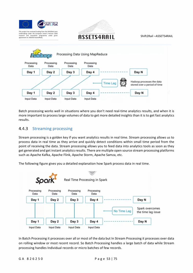
Shift2Rail –ASSETS4RAIL
G A 8 2 6 2 5 0 P a g e 53 | 75
This project has received funding from the Shift2Rail JointUndertaking under the European Union’s Horizon 2020research and innovation programme under grantagreement no. 826250 Assets4Rail).
Batch processing works well in situations where you don’t need real-time analytics results, and when it ismore important to process large volumes of data to get more detailed insights than it is to get fast analyticsresults.
Streaming processing
Stream processing is a golden key if you want analytics results in real time. Stream processing allows us toprocess data in real time as they arrive and quickly detect conditions within small time period from thepoint of receiving the data. Stream processing allows you to feed data into analytics tools as soon as theyget generated and get instant analytics results. There are multiple open source stream processing platformssuch as Apache Kafka, Apache Flink, Apache Storm, Apache Samza, etc.
The following figure gives you a detailed explanation how Spark process data in real time.
In Batch Processing it processes over all or most of the data but In Stream Processing it processes over data
on rolling window or most recent record. So Batch Processing handles a large batch of data while Stream
processing handles Individual records or micro batches of few records.
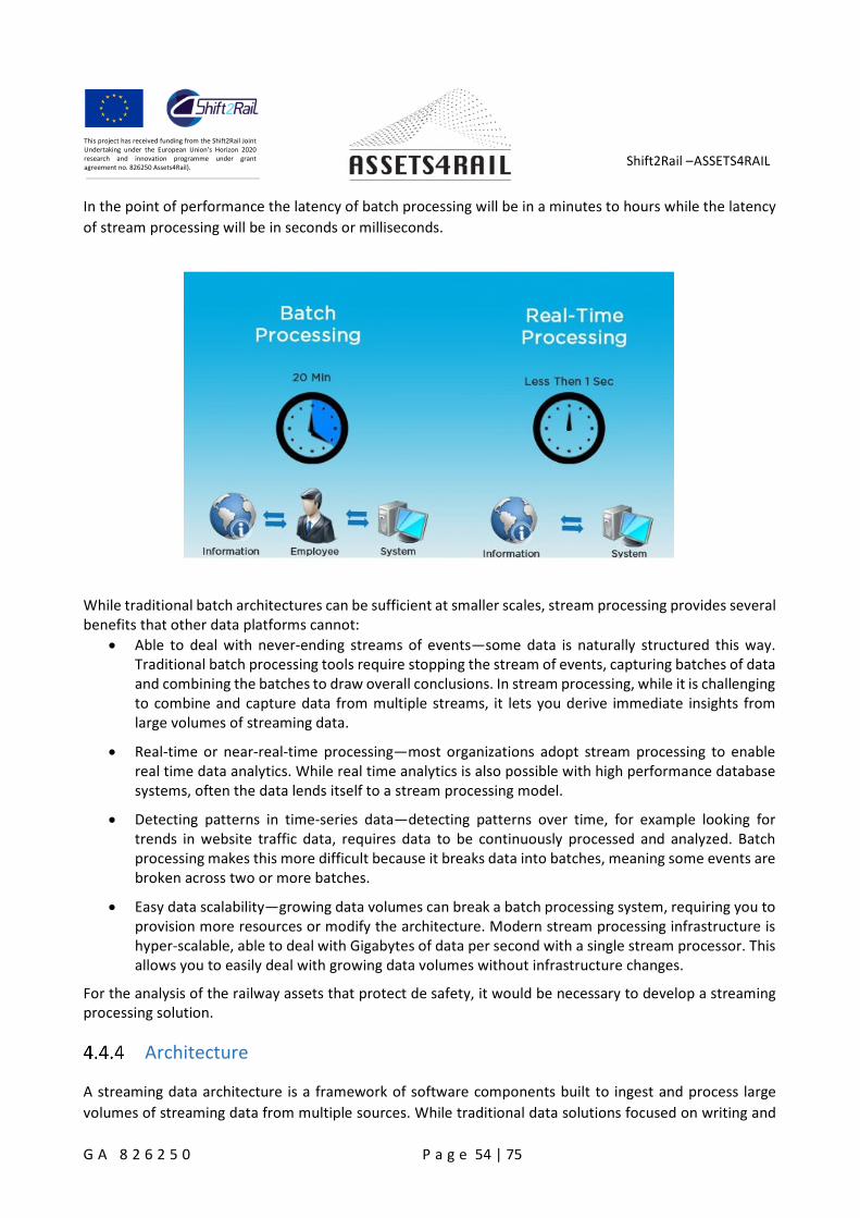
Shift2Rail –ASSETS4RAIL
G A 8 2 6 2 5 0 P a g e 54 | 75
This project has received funding from the Shift2Rail JointUndertaking under the European Union’s Horizon 2020research and innovation programme under grantagreement no. 826250 Assets4Rail).
In the point of performance the latency of batch processing will be in a minutes to hours while the latency
of stream processing will be in seconds or milliseconds.
While traditional batch architectures can be sufficient at smaller scales, stream processing provides severalbenefits that other data platforms cannot:
Able to deal with never-ending streams of events—some data is naturally structured this way.Traditional batch processing tools require stopping the stream of events, capturing batches of dataand combining the batches to draw overall conclusions. In stream processing, while it is challengingto combine and capture data from multiple streams, it lets you derive immediate insights fromlarge volumes of streaming data.
Real-time or near-real-time processing—most organizations adopt stream processing to enablereal time data analytics. While real time analytics is also possible with high performance databasesystems, often the data lends itself to a stream processing model.
Detecting patterns in time-series data—detecting patterns over time, for example looking fortrends in website traffic data, requires data to be continuously processed and analyzed. Batchprocessing makes this more difficult because it breaks data into batches, meaning some events arebroken across two or more batches.
Easy data scalability—growing data volumes can break a batch processing system, requiring you toprovision more resources or modify the architecture. Modern stream processing infrastructure ishyper-scalable, able to deal with Gigabytes of data per second with a single stream processor. Thisallows you to easily deal with growing data volumes without infrastructure changes.
For the analysis of the railway assets that protect de safety, it would be necessary to develop a streamingprocessing solution.
Architecture
A streaming data architecture is a framework of software components built to ingest and process large
volumes of streaming data from multiple sources. While traditional data solutions focused on writing and
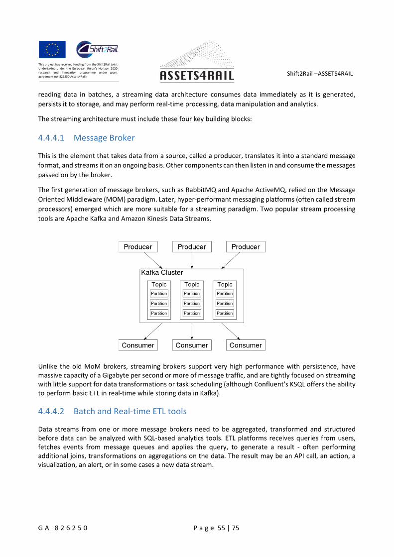
Shift2Rail –ASSETS4RAIL
G A 8 2 6 2 5 0 P a g e 55 | 75
This project has received funding from the Shift2Rail JointUndertaking under the European Union’s Horizon 2020research and innovation programme under grantagreement no. 826250 Assets4Rail).
reading data in batches, a streaming data architecture consumes data immediately as it is generated,
persists it to storage, and may perform real-time processing, data manipulation and analytics.
The streaming architecture must include these four key building blocks:
4.4.4.1 Message Broker
This is the element that takes data from a source, called a producer, translates it into a standard message
format, and streams it on an ongoing basis. Other components can then listen in and consume the messages
passed on by the broker.
The first generation of message brokers, such as RabbitMQ and Apache ActiveMQ, relied on the Message
Oriented Middleware (MOM) paradigm. Later, hyper-performant messaging platforms (often called stream
processors) emerged which are more suitable for a streaming paradigm. Two popular stream processing
tools are Apache Kafka and Amazon Kinesis Data Streams.
Unlike the old MoM brokers, streaming brokers support very high performance with persistence, havemassive capacity of a Gigabyte per second or more of message traffic, and are tightly focused on streamingwith little support for data transformations or task scheduling (although Confluent's KSQL offers the abilityto perform basic ETL in real-time while storing data in Kafka).
4.4.4.2 Batch and Real-time ETL tools
Data streams from one or more message brokers need to be aggregated, transformed and structuredbefore data can be analyzed with SQL-based analytics tools. ETL platforms receives queries from users,fetches events from message queues and applies the query, to generate a result - often performingadditional joins, transformations on aggregations on the data. The result may be an API call, an action, avisualization, an alert, or in some cases a new data stream.
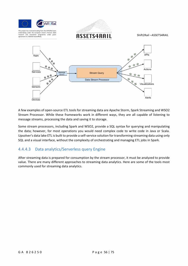
Shift2Rail –ASSETS4RAIL
G A 8 2 6 2 5 0 P a g e 56 | 75
This project has received funding from the Shift2Rail JointUndertaking under the European Union’s Horizon 2020research and innovation programme under grantagreement no. 826250 Assets4Rail).
A few examples of open-source ETL tools for streaming data are Apache Storm, Spark Streaming and WSO2
Stream Processor. While these frameworks work in different ways, they are all capable of listening to
message streams, processing the data and saving it to storage.
Some stream processors, including Spark and WSO2, provide a SQL syntax for querying and manipulating
the data; however, for most operations you would need complex code to write code in Java or Scala.
Upsolver's data lake ETL is built to provide a self-service solution for transforming streaming data using only
SQL and a visual interface, without the complexity of orchestrating and managing ETL jobs in Spark.
4.4.4.3 Data analytics/Serverless query Engine
After streaming data is prepared for consumption by the stream processor, it must be analyzed to providevalue. There are many different approaches to streaming data analytics. Here are some of the tools mostcommonly used for streaming data analytics.
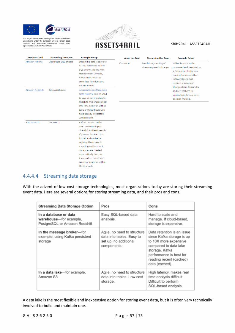
Shift2Rail –ASSETS4RAIL
G A 8 2 6 2 5 0 P a g e 57 | 75
This project has received funding from the Shift2Rail JointUndertaking under the European Union’s Horizon 2020research and innovation programme under grantagreement no. 826250 Assets4Rail).
4.4.4.4 Streaming data storage
With the advent of low cost storage technologies, most organizations today are storing their streamingevent data. Here are several options for storing streaming data, and their pros and cons.
A data lake is the most flexible and inexpensive option for storing event data, but it is often very technically
involved to build and maintain one.
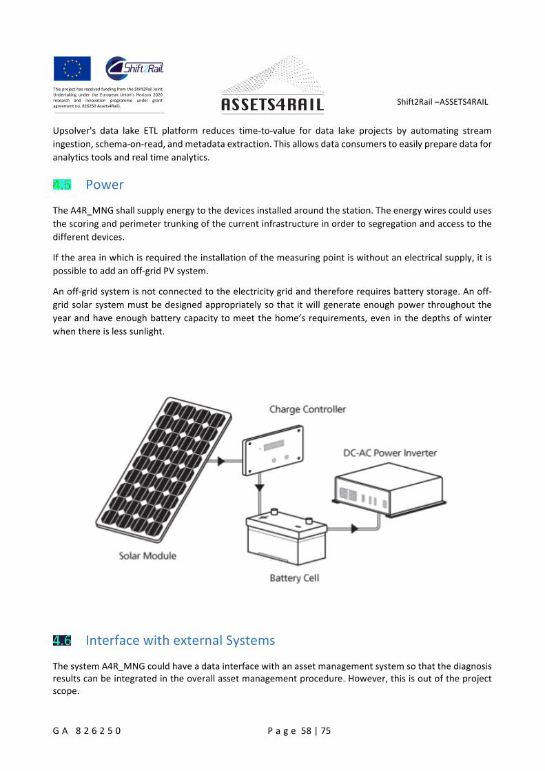
Shift2Rail –ASSETS4RAIL
G A 8 2 6 2 5 0 P a g e 58 | 75
This project has received funding from the Shift2Rail JointUndertaking under the European Union’s Horizon 2020research and innovation programme under grantagreement no. 826250 Assets4Rail).
Upsolver's data lake ETL platform reduces time-to-value for data lake projects by automating stream
ingestion, schema-on-read, and metadata extraction. This allows data consumers to easily prepare data for
analytics tools and real time analytics.
Power
The A4R_MNG shall supply energy to the devices installed around the station. The energy wires could uses
the scoring and perimeter trunking of the current infrastructure in order to segregation and access to the
different devices.
If the area in which is required the installation of the measuring point is without an electrical supply, it is
possible to add an off-grid PV system.
An off-grid system is not connected to the electricity grid and therefore requires battery storage. An off-
grid solar system must be designed appropriately so that it will generate enough power throughout the
year and have enough battery capacity to meet the home’s requirements, even in the depths of winter
when there is less sunlight.
Interface with external Systems
The system A4R_MNG could have a data interface with an asset management system so that the diagnosisresults can be integrated in the overall asset management procedure. However, this is out of the projectscope.
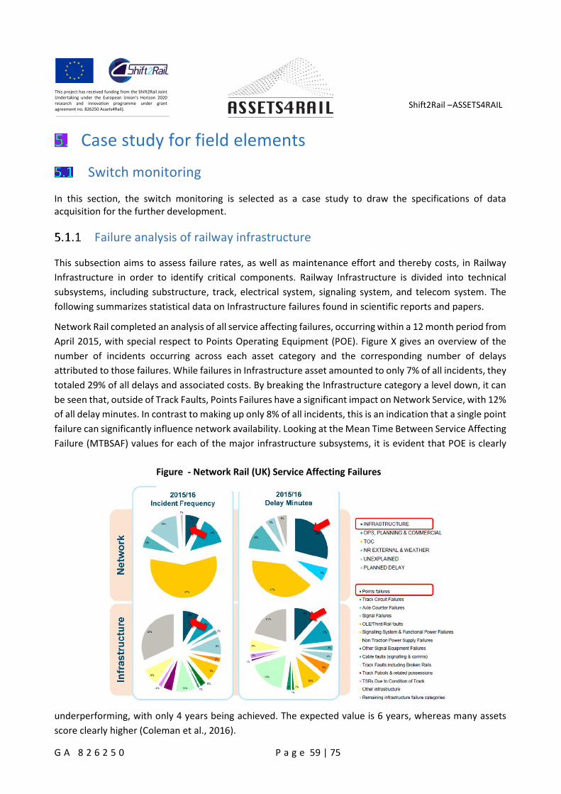
Shift2Rail –ASSETS4RAIL
G A 8 2 6 2 5 0 P a g e 59 | 75
This project has received funding from the Shift2Rail JointUndertaking under the European Union’s Horizon 2020research and innovation programme under grantagreement no. 826250 Assets4Rail).
Case study for field elements
Switch monitoring
In this section, the switch monitoring is selected as a case study to draw the specifications of dataacquisition for the further development.
Failure analysis of railway infrastructure
This subsection aims to assess failure rates, as well as maintenance effort and thereby costs, in Railway
Infrastructure in order to identify critical components. Railway Infrastructure is divided into technical
subsystems, including substructure, track, electrical system, signaling system, and telecom system. The
following summarizes statistical data on Infrastructure failures found in scientific reports and papers.
Network Rail completed an analysis of all service affecting failures, occurring within a 12 month period from
April 2015, with special respect to Points Operating Equipment (POE). Figure X gives an overview of the
number of incidents occurring across each asset category and the corresponding number of delays
attributed to those failures. While failures in Infrastructure asset amounted to only 7% of all incidents, they
totaled 29% of all delays and associated costs. By breaking the Infrastructure category a level down, it can
be seen that, outside of Track Faults, Points Failures have a significant impact on Network Service, with 12%
of all delay minutes. In contrast to making up only 8% of all incidents, this is an indication that a single point
failure can significantly influence network availability. Looking at the Mean Time Between Service Affecting
Failure (MTBSAF) values for each of the major infrastructure subsystems, it is evident that POE is clearly
underperforming, with only 4 years being achieved. The expected value is 6 years, whereas many assets
score clearly higher (Coleman et al., 2016).
Figure - Network Rail (UK) Service Affecting Failures
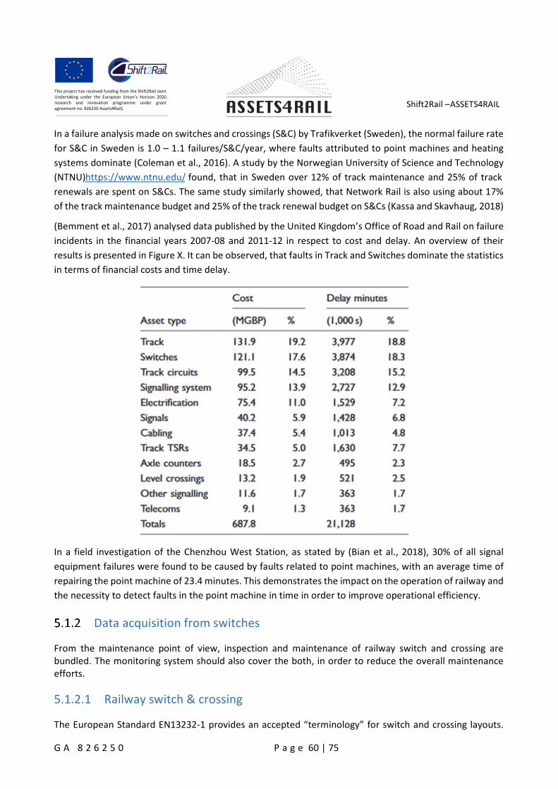
Shift2Rail –ASSETS4RAIL
G A 8 2 6 2 5 0 P a g e 60 | 75
This project has received funding from the Shift2Rail JointUndertaking under the European Union’s Horizon 2020research and innovation programme under grantagreement no. 826250 Assets4Rail).
In a failure analysis made on switches and crossings (S&C) by Trafikverket (Sweden), the normal failure rate
for S&C in Sweden is 1.0 – 1.1 failures/S&C/year, where faults attributed to point machines and heating
systems dominate (Coleman et al., 2016). A study by the Norwegian University of Science and Technology
(NTNU)https://www.ntnu.edu/ found, that in Sweden over 12% of track maintenance and 25% of track
renewals are spent on S&Cs. The same study similarly showed, that Network Rail is also using about 17%
of the track maintenance budget and 25% of the track renewal budget on S&Cs (Kassa and Skavhaug, 2018)
(Bemment et al., 2017) analysed data published by the United Kingdom’s Office of Road and Rail on failure
incidents in the financial years 2007-08 and 2011-12 in respect to cost and delay. An overview of their
results is presented in Figure X. It can be observed, that faults in Track and Switches dominate the statistics
in terms of financial costs and time delay.
In a field investigation of the Chenzhou West Station, as stated by (Bian et al., 2018), 30% of all signal
equipment failures were found to be caused by faults related to point machines, with an average time of
repairing the point machine of 23.4 minutes. This demonstrates the impact on the operation of railway and
the necessity to detect faults in the point machine in time in order to improve operational efficiency.
Data acquisition from switches
From the maintenance point of view, inspection and maintenance of railway switch and crossing arebundled. The monitoring system should also cover the both, in order to reduce the overall maintenanceefforts.
5.1.2.1 Railway switch & crossing
The European Standard EN13232-1 provides an accepted “terminology” for switch and crossing layouts.
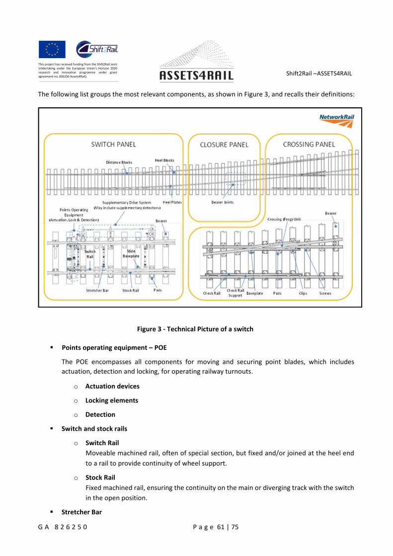
Shift2Rail –ASSETS4RAIL
G A 8 2 6 2 5 0 P a g e 61 | 75
This project has received funding from the Shift2Rail JointUndertaking under the European Union’s Horizon 2020research and innovation programme under grantagreement no. 826250 Assets4Rail).
The following list groups the most relevant components, as shown in Figure 3, and recalls their definitions:
Figure 3 - Technical Picture of a switch
Points operating equipment – POE
The POE encompasses all components for moving and securing point blades, which includes
actuation, detection and locking, for operating railway turnouts.
o Actuation devices
o Locking elements
o Detection
Switch and stock rails
o Switch Rail
Moveable machined rail, often of special section, but fixed and/or joined at the heel end
to a rail to provide continuity of wheel support.
o Stock Rail
Fixed machined rail, ensuring the continuity on the main or diverging track with the switch
in the open position.
Stretcher Bar
Shift2Rail –ASSETS4RAIL
G A 8 2 6 2 5 0 P a g e 62 | 75
This project has received funding from the Shift2Rail JointUndertaking under the European Union’s Horizon 2020research and innovation programme under grantagreement no. 826250 Assets4Rail).
Part joining the two switch rails of the same set of switches.
Check Rails
Special section bar ensuring (by guidance of the wheel) the safe passage of the axle opposite the
neck gap of the common crossing.
Crossing (Frog) Unit
Arrangement ensuring the intersection of two opposite running edges of turnouts or diamond
crossings and having one crossing vee and two wing rails.
Plates
o Slide baseplate
Part which supports and retains the stock rail and a flat surface upon which the foot of the
switch rail slides.
o Switch and crossing baseplate
Load distributing baseplate placed between the bearer and the feet of two or more rails.
Fastening Material
Bearers
A turnout bearer is a special type of railway sleeper that is used to support the rail when mainline
track ‘turns-out’ to form one or more diverging lines.
Ballast
Track ballast forms the trackbed upon which railroad ties (sleepers) are laid.
Relay
Signaling relay is the control element that transfers the control signals from the interlocking system
to the electrical circuits of the point machine.
5.1.2.2 Common failure modes
Table 1 lists the critical failure modes for each S&C subsystem in terms of severity and frequency, based onthe previous study in the IN2RAIL and IN2TRACK project.
Table 1 Common failure modes of the switches and crossings attributed to the subsystems (Coleman et
al., 2016) (DENLEY et al., 2018)
Component Failure Mode
POE - Actuationdevices
Backdrive mechanism failure including out-of-adjustment, loose and worncomponents
POE - Actuationdevices
Point motor failure including false adjustment of clutch, springs andincorrectly setup components
POE - Actuationdevices
Points failing to move
POE - Detection Incorrect detection assemblyPOE - Detection Points failing to detectPOE - Detection Supplementary detection failure

Shift2Rail –ASSETS4RAIL
G A 8 2 6 2 5 0 P a g e 63 | 75
This project has received funding from the Shift2Rail JointUndertaking under the European Union’s Horizon 2020research and innovation programme under grantagreement no. 826250 Assets4Rail).
POE - Lockingelements
Clamplock mechanism failure
POE - Lockingelements
Locking mechanism failure
POE – Heatingsystem
Heating system fails to heat
Switch and stockrails
Sideworn stock rail associated with little used switch
Switch and stockrails
Stock rail and switch rail both sideworn
Switch and stockrails
Stock rail headwear associated with a less head worn switch rail
Switch and stockrails
Switch rail damage
Switch and stockrails
Switch rail with a sharp gauge corner profile
Switch and stockrails
Rail defect through the machined length of the switch blade
Switch and stockrails
Rolling Contact Fatigue (RCF) through machined length of switch rail
Switch and stockrails
Lipping on switch and stock rail
Switch and stockrails
Spalling of stock rail
Switch and stockrails
Soft spots in the running surface
Switch and stockrails
Non-compliance of narrowest flangeway (residual switch opening)
Switch and stockrails
Incorrect lateral attachement of switch rail
Switch and stockrails
Debris in switch flangeway
Crossing (frog) unit Deformation of crossing nose and wear of wing rail due to wheelimpact/contact (Cast)
Crossing (frog) unit Deformation of crossing nose and wear of wing rail due to wheelimpact/contact (Fabricated and part fabricated)
Crossing (frog) unit Cracks in cast crossings from defects or damageCrossing (frog) unit Tri-metal weld defectCrossing (frog) unit Wear/damage to newly installed cast crossingCrossing (frog) unit Debris in crossing flangewayCrossing (frog) unit Cast crossing defects due to squats, wheelburns, batter, flaking/shelling,
metal breaking out of wheel transfer areaCheck Rails Excessive wear on check rails
Stretcher bar Cracked/broken stretcher bar, bracket or gooseneck ( fixed stretcher bar)Stretcher bar Cracked/fractured/broken stretcher bar or bracket ( adjustable stretcher
bar)
Baseplates Break of platesSlide plates Switch roller seizesSlide plates Contamination / Excessive wear of slide platesSlide plates Slide plate insert (pin) failure
Shift2Rail –ASSETS4RAIL
G A 8 2 6 2 5 0 P a g e 64 | 75
This project has received funding from the Shift2Rail JointUndertaking under the European Union’s Horizon 2020research and innovation programme under grantagreement no. 826250 Assets4Rail).
Fastening Material Break / Loosening of fastening elementsFastening Material Broken bolts / screwsFastening Material Broken fishplate
Bearers Rotten / broken timber bearersBearers Cracked / broken concrete bearersBearers Warped / twisted (crippled) bearerBearers Misaligned bearersBearers Worn gauge stopBallast Ballast degradation under switches
IN2Rail D2.1 (Coleman et al., 2016) analysed the failure distribution for point machine. It was found that
the largest contribution to total failures at Network Rail comes from the backdrive mechanism (POE
actuation), drive components (POE actuation), motor and actuator (POE actuation), detection components
(POE - Detection), baseplates and signaling relays, while the failures from POE actuation, detection system
and heating system dominate the overall failures of S&C at Trafikverket.
IN2TRACK D2.1 (DENLEY et al., 2018) carried out FMECA analysis on S&C and found that the most critical
failure modes are deformation, crack and wear of crossing(frog) unit, rolling contact fatigue (RCF) and
sideworn of switch rail
5.1.2.3 Existing data acquisition methods
C4R D1.3.1 lists the failure catalogue of S&C and the corresponding measurement methods for each failure
mode. In the current inspection routine, most failures are examined by visual inspection. The wear of the
profile is measured by track geometry coaches or measurement trolleys. In the modern point machines,
there are self-diagnostics module measuring current and voltage. The interlocking system contains the
information of operation duration of the point machines. However, the most existing conventional point
machines and interlocking systems cannot provide any digital data for diagnosis. Additional sensors are
required for data acquisition. IN2TRACK D2.3 splited the S&C measurements into three monitoring
categories (Turner et al., 2019):
During switch movement
During train passage, either from trackside or on-board sensors
Environmental conditions when an event happens (train passage or switch movement)
Switch movement
Measurement Data acquisition methods
Switch duration(time)
The duration of a throw can be determined from most sensor measurements thatdetect the start and end of a point machine being activated. It can also bedetermined based on the signalling relay switch on/off times.
Since a lot of infrastructure operators monitor their relay switch times, it is possibleto use just this for the simplest and cheapest form of monitoring.
Some faults can be detected from increased movement time and jitter in themovement duration.
Current Current can be monitored in-line by measuring a voltage across a resistance or using a non-
Shift2Rail –ASSETS4RAIL
G A 8 2 6 2 5 0 P a g e 65 | 75
This project has received funding from the Shift2Rail JointUndertaking under the European Union’s Horizon 2020research and innovation programme under grantagreement no. 826250 Assets4Rail).
contact current transducer such as the LEM PCM 30-P.Current is proportional to force but can only give us relative force change based on the effortof the motor and not static force.
Voltage Voltage can be non-invasively measured by e.g. a LEM AV100-500 sensor.Voltage can be used to identify power supply problems and detect increased resistance inmechanical switching contacts when the machine is not moving.
Force The driving force can be measured by a load pin, being fitted to replace a pin in the driveassembly or strain gauges around the switch to determine the stresses experiences bydifferent parts of the S&C during points movement and train passage.Unlike current and pressure which are used to drive the movement, such sensors can tell usthe static force when the machine is locked rather than just the change in force.
Displacement The displacement can be estimated from the current or directly measured by displacementtransducer.The displacement indicates if the switch rail is in the right position.
Train Passage
Acceleration Acceleration can be measured by accelerometer. It indicates the dynamic response of thestructure, such as sleeper, ballast and crossing nose, and can be used for abnormalitydetection and detection of the specific failures.
Noise Noise can be structure-borne noise which is measured by accelerometers or acoustic emissionsensors. Noise can also be air-borne noise which is measured by microphone. Noise is similaras acceleration, indicating the dynamic response of the structure.
Environmental conditions
Temperature andhumidity
Temperature and humidity can be measured by Temperature and humidity sensors.Since the aforementioned measurements could be affected by season and weather. TheTemperature and humidity could be used to compensate for season and weather.
It is essential to understand the characteristics of the measurements under the specific failure modes in
order to choose the proper parameters for diagnosis and prognosis of the specific failure modes. Asada
(2013) proposed the monitoring solutions for overdriving/underdriving of the driver rod (belonging to POE
actuation). This failure results in out-of-adjustment in Table 1. The drive force, the electrical current and
voltage were collected for diagnosis. Silmon (2009) measured the current, force and displacement to detect
the misadjustment of the backdrive and overdriving of the driver rod (belonging to POE actuation). Lee et
al. (2016) used microphone measurements for diagnosis of obstruction issues, such as ice obstruction,
ballast obstruction and slackened nut.
The data acquisition is triggered by the event. In this case, the measured parameters in the category of
“Switch movement” is triggered by switch movement. The measurement should last the entire operation.
It is desired to send all of raw data to the central back-office to collect as much as possible data, ensuring
the robustness and the continuous improvement of the developed data processing algorithms. However,
it takes more resources to transmit, store and process data. Alternatively, edge computing could be applied
to extract the most important information from the raw data and send back only the extracted information.
This takes less resources, but does not allow update and improvement of the developed data processing
algorithms.
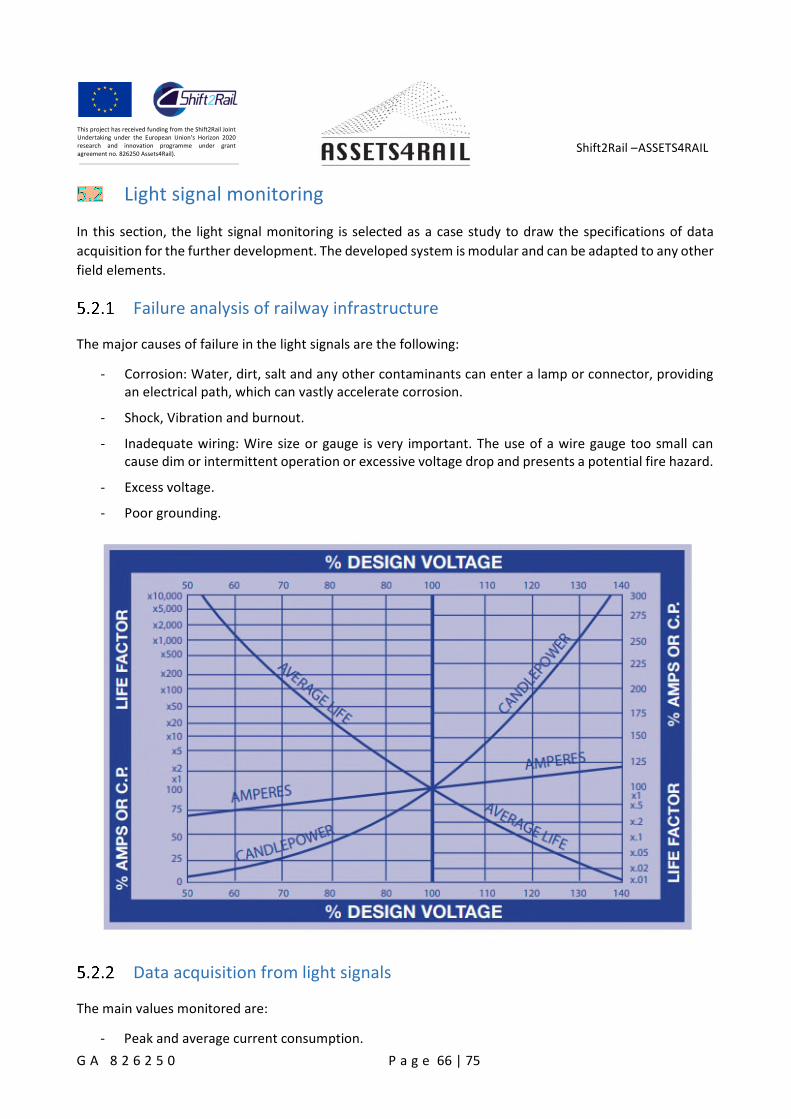
Shift2Rail –ASSETS4RAIL
G A 8 2 6 2 5 0 P a g e 66 | 75
This project has received funding from the Shift2Rail JointUndertaking under the European Union’s Horizon 2020research and innovation programme under grantagreement no. 826250 Assets4Rail).
Light signal monitoring
In this section, the light signal monitoring is selected as a case study to draw the specifications of data
acquisition for the further development. The developed system is modular and can be adapted to any other
field elements.
Failure analysis of railway infrastructure
The major causes of failure in the light signals are the following:
- Corrosion: Water, dirt, salt and any other contaminants can enter a lamp or connector, providingan electrical path, which can vastly accelerate corrosion.
- Shock, Vibration and burnout.
- Inadequate wiring: Wire size or gauge is very important. The use of a wire gauge too small cancause dim or intermittent operation or excessive voltage drop and presents a potential fire hazard.
- Excess voltage.
- Poor grounding.
Data acquisition from light signals
The main values monitored are:
- Peak and average current consumption.
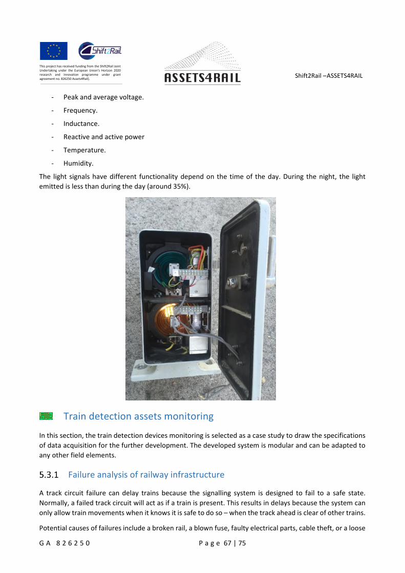
Shift2Rail –ASSETS4RAIL
G A 8 2 6 2 5 0 P a g e 67 | 75
This project has received funding from the Shift2Rail JointUndertaking under the European Union’s Horizon 2020research and innovation programme under grantagreement no. 826250 Assets4Rail).
- Peak and average voltage.
- Frequency.
- Inductance.
- Reactive and active power
- Temperature.
- Humidity.
The light signals have different functionality depend on the time of the day. During the night, the light
emitted is less than during the day (around 35%).
Train detection assets monitoring
In this section, the train detection devices monitoring is selected as a case study to draw the specifications
of data acquisition for the further development. The developed system is modular and can be adapted to
any other field elements.
Failure analysis of railway infrastructure
A track circuit failure can delay trains because the signalling system is designed to fail to a safe state.
Normally, a failed track circuit will act as if a train is present. This results in delays because the system can
only allow train movements when it knows it is safe to do so – when the track ahead is clear of other trains.
Potential causes of failures include a broken rail, a blown fuse, faulty electrical parts, cable theft, or a loose
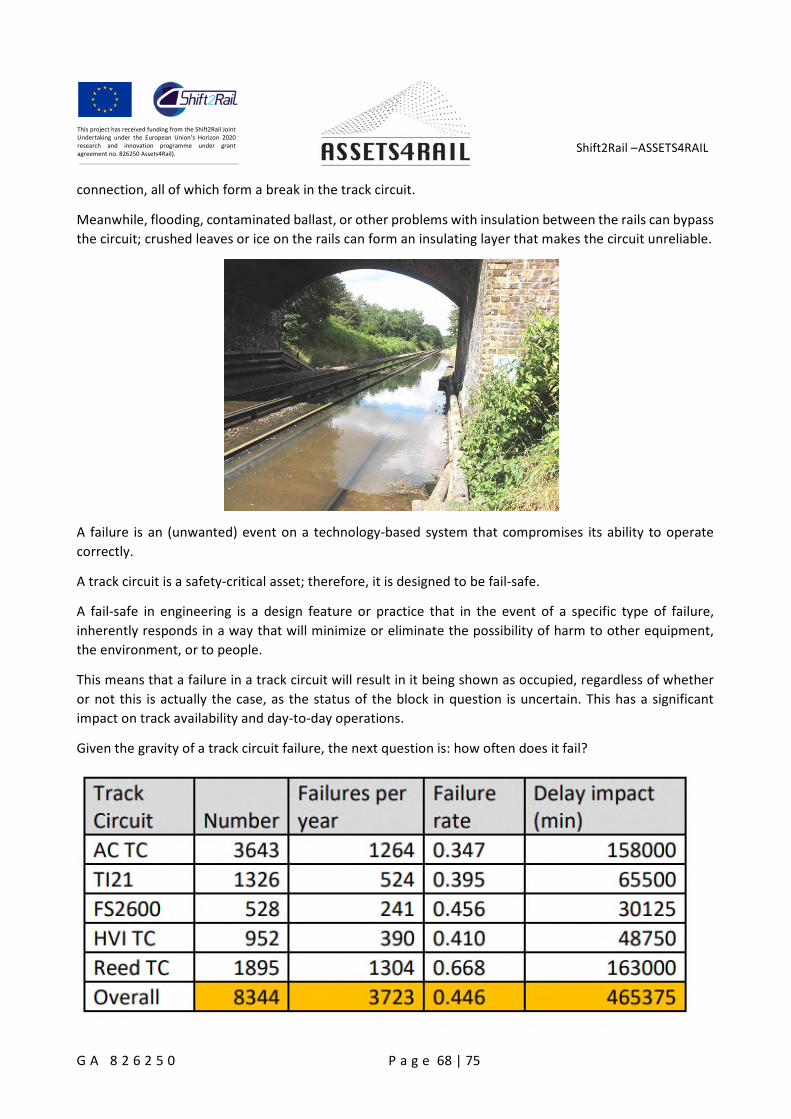
Shift2Rail –ASSETS4RAIL
G A 8 2 6 2 5 0 P a g e 68 | 75
This project has received funding from the Shift2Rail JointUndertaking under the European Union’s Horizon 2020research and innovation programme under grantagreement no. 826250 Assets4Rail).
connection, all of which form a break in the track circuit.
Meanwhile, flooding, contaminated ballast, or other problems with insulation between the rails can bypass
the circuit; crushed leaves or ice on the rails can form an insulating layer that makes the circuit unreliable.
A failure is an (unwanted) event on a technology-based system that compromises its ability to operate
correctly.
A track circuit is a safety-critical asset; therefore, it is designed to be fail-safe.
A fail-safe in engineering is a design feature or practice that in the event of a specific type of failure,
inherently responds in a way that will minimize or eliminate the possibility of harm to other equipment,
the environment, or to people.
This means that a failure in a track circuit will result in it being shown as occupied, regardless of whether
or not this is actually the case, as the status of the block in question is uncertain. This has a significant
impact on track availability and day-to-day operations.
Given the gravity of a track circuit failure, the next question is: how often does it fail?
Shift2Rail –ASSETS4RAIL
G A 8 2 6 2 5 0 P a g e 69 | 75
This project has received funding from the Shift2Rail JointUndertaking under the European Union’s Horizon 2020research and innovation programme under grantagreement no. 826250 Assets4Rail).
According to a recent study “Condition Monitoring of Audio Frequency Track Circuits -” by the University
of Railway Engineering of Birmingham, there are nearly 80,000 track circuits in operation on the mainline
railway network within the UK. Table shows the number of track circuits installed in Network Rail’s Southern
Zone together with typical failure statistics.
The average failure rate is around 45% per year per installation, and any track circuit failure can cause
significant disruption to rail services.
Over 12,000 track circuit failures were reported in the UK during one operational year, resulting in 1.5
million minutes of delay. Typically, the infrastructure operators are penalized by £20– £60 per delay minute
arising from infrastructure failure, but in the case of a heavily used network section, this can go up to £250
per delay minute.
Therefore, the ability to detect and diagnose track circuit failures to provide a fast response to
failures/incidents has a significant economic benefit.
The following failure examples can be critical either in terms of availability and/or safety:
- Shunt failure: A Shunt Failure (safety critical) occurs when the short circuit current cannot be
measured correctly; therefore, the device is not able to perform its main function. This type of
failure might occur for a number of different reasons. For example, a broken or oxidized rail, or a
failure in transverse impedances (for TC equipped with electrical joints) are among some of the
most frequent causes of shunt failure.
- Frequency Drift: Frequency drifting is an unintended and generally arbitrary offset of an oscillator
from its nominal frequency, due to component aging, changes in temperature, or problems with
the voltage transmitter. It is a common problem in AC Audio Frequency track circuits, since it
impairs the correct operation of all frequency tuned elements, creating track availability issues.
- Leaking Electrical Joints (Tuning units): In the case of jointless AC track circuits, one of the most
common failures takes place in electrical joint components, such as the LC tuned passive
components which are affected by drifting capacitance. The tuned LC components fail to properly
filter and separate adjacent frequencies from the side segment, producing a leak (also known as
longitudinal crosstalk) from one track circuit segment to another. This can severely impair the
correct detection of the train, causing the segment to look occupied when it is not.
Data acquisition from train detection assets
Remote Condition Monitoring (RCM) is the process of monitoring a number of parameters in a device, in
order to identify any significant changes which may indicate that a fault is developing.
In the case of track circuits, a common form of RCM is to constantly measure the current levels at the track
circuit receiver for free and occupied segments. Unfortunately, this cannot guarantee a preventative
approach, because the relationship between the Track Circuit parameters along the track and the current
value at the receiver and transmitter ends is not linear. This means that they are not good indicators of a
potential failure.
To be defined as comprehensive and effective, each measurement session should be able to detect and
assess the quality of the following parameters:
Shift2Rail –ASSETS4RAIL
G A 8 2 6 2 5 0 P a g e 70 | 75
This project has received funding from the Shift2Rail JointUndertaking under the European Union’s Horizon 2020research and innovation programme under grantagreement no. 826250 Assets4Rail).
- Icc (shunt current) levels for each relevant frequency
- Transversal elements (electrical joints)
- Compensating capacitors, if present, along the track
- Data transmission modulation and verification for both pointwise and continuously transmitted
data.
Level crossings monitoring
In this section, the level crossings monitoring is selected as a case study to draw the specifications of data
acquisition for the further development. The developed system is modular and can be adapted to any other
field elements.
Failure analysis of railway infrastructure
The major causes of failure in the level crossings are the following:
- Power supply is out of limits for correct operation.
- Lights
- audible alert
- gate and boom arm emergency switches
- Battery voltage health indication
Data acquisition from level crossings
Level crossing monitoring systems detect and record the condition of a level crossing, typically those fitted
with protections and warnings for vehicular and/or pedestrian traffic. This includes traffic booms and/or
pedestrian gates, with visible and audible alerts.
Level crossing monitoring systems (hereafter referred to as the monitoring system) are deployed to comply
with safety integrity requirements, or to support improved maintenance practices.
A monitoring system is used to comply with safety integrity requirements at actively controlled level
crossings, by monitoring and recording the status of various components of the level crossing. The
monitoring system may also be used for maintenance purposes.
Remote monitoring of level crossing status and live reporting of failure conditions should be provided,
where it is reasonably practicable to implement a communications link.
As a minimum, a level crossing monitoring system shall monitor and record:
- operation of the level crossing;
- availability of primary power supply;
- primary power supply or battery voltage:
Shift2Rail –ASSETS4RAIL
G A 8 2 6 2 5 0 P a g e 71 | 75
This project has received funding from the Shift2Rail JointUndertaking under the European Union’s Horizon 2020research and innovation programme under grantagreement no. 826250 Assets4Rail).
- timing and operation of visual and audible alerts and, where applicable, boom barriers and/or
pedestrian gates;
- train detection systems and associated circuitry;
- controls that operate, override or test the level crossing system.
The monitoring system should have a facility to prevent false alarms being raised during maintenance tasks
(also known as maintenance mode).
The monitoring system may include (but is not limited to) any of the following:
- Level crossing monitoring and communications hardware.
- Level crossing power supply and battery system.
- Level crossing obstruction detection system.
- Monitoring location system, e.g. GPS.
- Wayside monitoring systems.
- Environmental monitoring, e.g. temperature, rainfall, rock slip, etc.
Level crossings may also be remotely monitored via Closed-Circuit Television (CCTV) cameras. CCTV can be
a component of the monitoring system or an independent system.
Digital Inputs:
The following non-exhaustive list is the types of digital inputs:
- Train detection systems and associated circuitry.
- The level crossing control and repeat relays.
- Test switch.
- Door switch.
- Gate and boom arm state.
- Lights, audible alert, gate and boom arm emergency switches.
- Power supply state indication.
- Battery voltage health indication.
- Any other function that qualifies the operation of the Level Crossing (for example approach signals).
- Audible alert state.
- Reset fault or warning.
- Output state of each flasher.
- Other relays/contacts of interest.

Shift2Rail –ASSETS4RAIL
G A 8 2 6 2 5 0 P a g e 72 | 75
This project has received funding from the Shift2Rail JointUndertaking under the European Union’s Horizon 2020research and innovation programme under grantagreement no. 826250 Assets4Rail).
- Other wayside monitoring peripherals.
Analog inputs:
The functionality of the analogue inputs may include:
- battery and/or power supply monitoring;
- lamp driver/flasher unit correct operation;
- individual lamp health; and
- audible alert monitoring;
Shift2Rail –ASSETS4RAIL
G A 8 2 6 2 5 0 P a g e 73 | 75
This project has received funding from the Shift2Rail JointUndertaking under the European Union’s Horizon 2020research and innovation programme under grantagreement no. 826250 Assets4Rail).
Conclusions
This deliverable described the overall concept of the data collection from the fail-safe systems which refers
to the railway signaling and control systems. Based on the fact that the base element of a railway signaling
system is the interlocking system. For one region, there is one interlocking system, controlling the
distributed field elements. Therefore, a high-level architecture of the data collection system The
A4R_SYSTEM has been designed for the interlocking system. The A4R_SYSTEM creates a network of capture
and concentration of data to be analyzed. The data could be potentially collected from the interlocking
system, technical rooms and diverse field elements.
The core elements of A4R_SYSTEM are the data acquisition nodes. In principle, there are two ways of data
acquisition. The first is to directly read the existing data from the target systems, in case that the target
systems are digitalized and have data interface. For the EULYNX compliant interlocking systems and field
elements, all data processed and stored together with the outputs are shown in the maintenance support
system of each interlocking. This system shows all the main data values, alarms, processor logs, debug logs.
The maintenance assistance systems have different protocols depending on each technologist, so it is
necessary to define a standard protocol ensuring the interoperability.
Although EULYNX was proposed for standardizing signaling systems, the majority of the existinginterlocking systems are not compliant with EULYNX. For the traditional mechanical and relay basedinterlocking systems, additional sensors are required. Therefore, the second way is to measure theparameters by adding sensors. Depending on the target systems, the sensors could be installed in thetechnical rooms and/or directly on the field elements. Several case studies are performed to figure out thecommon failure modes of the field elements and the measurement methods for key parameters:
Switches (incl. point machine): current, voltage, force, displacement, accelerations, noise andswitch duration, temperature and humidity.
Light signals: current, voltage, inductance, frequency, power, temperature and humidity
Train detection (track circuit): shunt current levels for each relevant frequency, transversalelements (electrical joints) and compensating capacitors
Level crossing: control and repeat relays, test switch, door switch, gate and boom arm state, lights,
audible alert; gate and boom arm emergency switches; power supply state; battery voltage; reset
fault or warning, output state of each flasher; other relays/contacts of interest; battery and/or
power supply monitoring; lamp driver/flasher unit correct operation; individual lamp health;
The data acquisition can be triggered by the event, i.e. either an operation action or a train passage. Aftermeasurements, the data could be either processed on site or directly transmitted. It depends on the designof the diagnostic system and the restriction of power supply and communication facilities.
Since the difference of the existing interlocking systems, it is recommended to identify a specific
interlocking system and a specific field element for the further development of the data acquisition nodes
and the diagnostic algorithm. The data acquisition node should also be a modular system and easily adapted
to different field elements to be monitored by replacing sensors.
Shift2Rail –ASSETS4RAIL
G A 8 2 6 2 5 0 P a g e 74 | 75
This project has received funding from the Shift2Rail JointUndertaking under the European Union’s Horizon 2020research and innovation programme under grantagreement no. 826250 Assets4Rail).
References
[1]. Gerhards, Rainer. The Syslog Protocol. doi:10.17487/RFC5424. RFC 5424
[2]. https://en.wikipedia.org/wiki/Syslog
[3]. Eulynx project. https://www.eulynx.eu/
[4]. Train Communication Networks. Johan Holmberg. 11.12.2015
[5]. Next-Gen Train Control / Management (TCMS) Architectures: “Drive-By-Data” System IntegrationApproach. Mirko Jakovljevic, Arjan Geven, Natasa Simanic-John, Derya Mete Saatci
[6]. ICT STANDARDISATION ON BOARD OF TRAINS. An overview of current and upcoming standards.Gianosvaldo Fadin
[7]. Especificación Técnica: Servicio de mantenimiento de instalaciones de Seguridad y motorización dedesvíos. RENFE
[8]. CONSISTENCIAS BÁSICAS MANTENIMIENTO INSTALACIONES DE SEGURIDAD. Euskal Trenbide Sarea
[9]. Track circuit life check. ERTMS Solutions
[10]. Predictive Maintenance of Railway Point Machines.Sandeep Patalay
[11]. On Analysis of the Predictive Maintenance of Railway Points. Processes and Possibilities.Jussi Ojala
[12]. Redundant server architectures from E2E Networks. https://www.e2enetworks.com/help/knowledge-base/redundant-server-architectures-from-e2e-networks/
[13]. Big data culture an evolving strategy for IoT in rail. IRJ.https://www.railjournal.com/in_depth/big-data-culture-strategy-iot-rail
[14]. The 6 Stages of Data Processing Cycle. PeerXP Team
[15]. Eran Levy. 4 Key Components of a Streaming Data Architecture (with Examples)
Jussi Ojala (2018), On Analysis of the Predictive Maintenance of Railway Points, Master’s Thesis, AaltoUniversity
Lan Coleman et al. (2016), Development of Novel S&C Motion/Locking Mechanisms: Design ConceptReport, IN2RAIL (INNOVATIVE INTELLIGENT RAIL) Deliverable D2.1Melanie DENLEY et al. (2018), Identifying and Understanding Core S&C Issues, IN2TRACK (Research intoenhanced tracks, switches and structures) Deliverable D2.1TOMOTSUGU ASADA (2013), Novel condition monitoring techniques applied to improve the dependabilityof railway point machines, PhD thesis, University of BirminghamC4R (2015), Operational failure modes of Switches and Crossings, Capycity for Rail project DeliverableD1.3.1Andrew TURNER et al. (2019), Enhanced monitoring, operation, control and maintenance of S&C, IN2TRACKDeliverable D2.3Joseph Alan Silmon (2009), OPERATIONAL INDUSTRIAL FAULT DETECTION AND DIAGNOSIS: RAILWAY

Shift2Rail –ASSETS4RAIL
G A 8 2 6 2 5 0 P a g e 75 | 75
This project has received funding from the Shift2Rail JointUndertaking under the European Union’s Horizon 2020research and innovation programme under grantagreement no. 826250 Assets4Rail).
ACTUATOR CASE STUDIES, doctor thesis, University of BirminghamJonguk Lee et al. (2016) Fault Detection and Diagnosis of Railway Point Machines by Sound Analysis,Kassa and Skavhaug (2018), Monitoring of switches & crossings (turnouts) and tracks, presentation, EUproject DESTination RAILBemment, S. D., Goodall, R. M., Dixon, R., & Ward, C. P. (2018). Improving the reliability and availability ofrailway track switching by analysing historical failure data and introducing functionally redundantsubsystems. Proceedings of the Institution of Mechanical Engineers, Part F: Journal of Rail and RapidTransit, 232(5), 1407–1424. https://doi.org/10.1177/0954409717727879Bian et al. (2018), Degradation Detection Method for Railway Point Machines, arxiv.org,https://arxiv.org/ftp/arxiv/papers/1809/1809.02349.pdf