D 9.1 - ESECMaSE
113
ESECMaSE Enhanced Safety and Efficient Construction of Masonry Structures in Europe Project No. Coll – Ct - 2003 - 500291 ESECMaSE Enhanced Safety and Efficient Construction of Masonry Structures in Europe Horizontal Research Activities Involving SMEs Collective Research Work Package N°: 9 D9.1 Proposals for an advanced design model of masonry under lateral loads for the implementation in Eurocode 6-1-1 Prof. Dr.-Ing. Wolfram Jäger, Dipl.-Ing. Peter Schöps Due date of deliverable: 10 November 2007 Actual submission date: 14 March 2008 Draft N°: 1 Start date of project: 10.June 2004 Duration: 45 month TU Dresden Faculty of Architecture Chair of Structural Design 01062 Dresden Project co-funded by the European Commission within the Sixth Framework Programme (2002-2006) Dissemination Level PU Public x PP Restricted to other programme participants (including the Commission Services) RE Restricted to a group specified by the consortium (including the Commission Services) CO Confidential, only for members of the consortium (including the Commission Services)
-
Upload
khangminh22 -
Category
Documents
-
view
3 -
download
0
Transcript of D 9.1 - ESECMaSE
ESECMaSEEnhanced Safety and Efficient Construction of Masonry Structures in Europe
Project No. Coll – Ct - 2003 - 500291
ESECMaSE
Enhanced Safety and Efficient Construction of Masonry Structures in Europe
Horizontal Research Activities Involving SMEs Collective Research Work Package N°: 9
D9.1 Proposals for an advanced design model of masonry under
lateral loads for the implementation in Eurocode 6-1-1
Prof. Dr.-Ing. Wolfram Jäger, Dipl.-Ing. Peter Schöps
Due date of deliverable: 10 November 2007 Actual submission date: 14 March 2008
Draft N°: 1
Start date of project: 10.June 2004 Duration: 45 month
TU Dresden Faculty of Architecture Chair of Structural Design 01062 Dresden
Project co-funded by the European Commission within the Sixth Framework Programme (2002-2006)
Dissemination Level
PU Public x
PP Restricted to other programme participants (including the Commission Services)
RE Restricted to a group specified by the consortium (including the Commission Services)
CO Confidential, only for members of the consortium (including the Commission Services)
ESECMaSEEnhanced Safety and Efficient Construction of Masonry Structures in Europe
TU Dresden Faculty of Architecture Chair of Structural Design
Table of contents
Deliverable 9.1 Page 1 of 112 Proposals for an advanced design model of masonry under lateral loads for the implementation in Eurocode 6-1-1
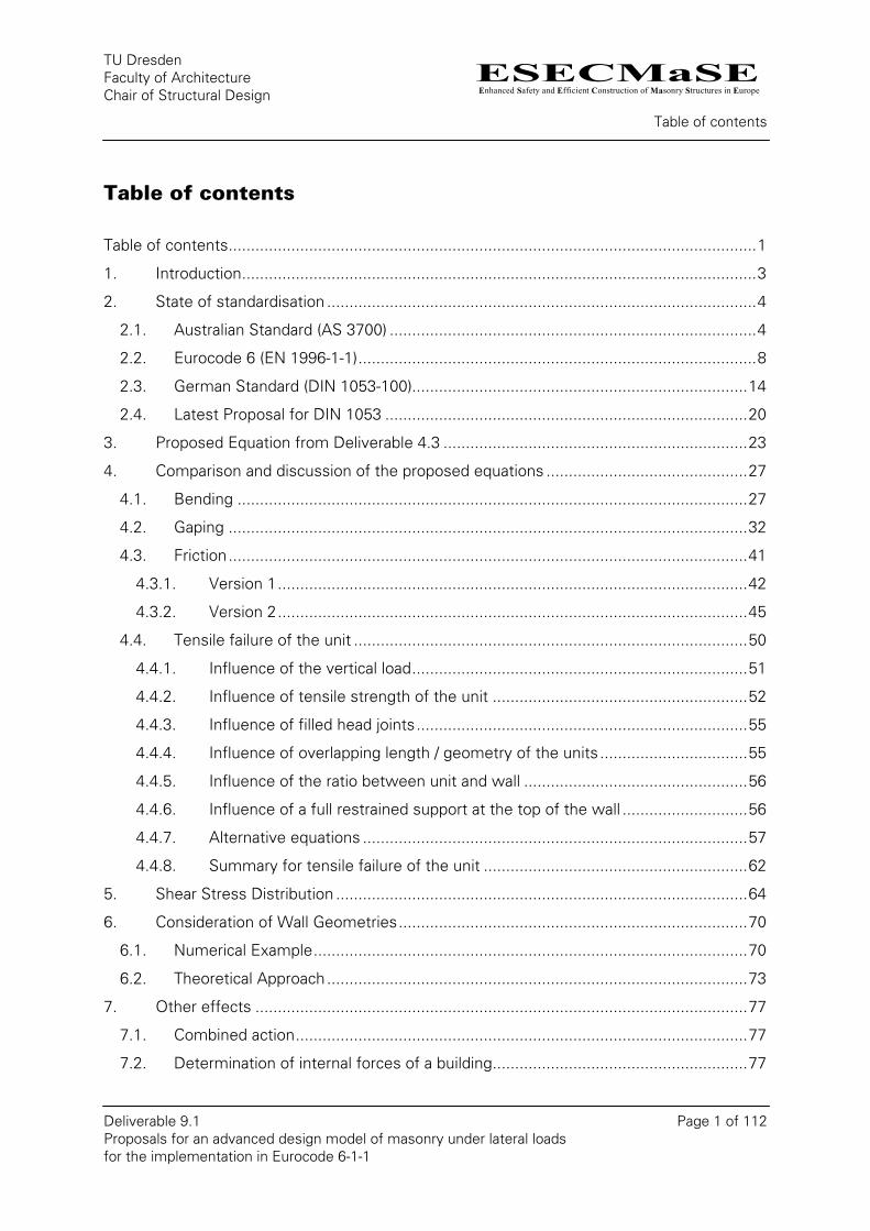
Table of contents
Table of contents......................................................................................................................1 1. Introduction...................................................................................................................3 2. State of standardisation ................................................................................................4
2.1. Australian Standard (AS 3700) ..................................................................................4 2.2. Eurocode 6 (EN 1996-1-1).........................................................................................8 2.3. German Standard (DIN 1053-100)...........................................................................14 2.4. Latest Proposal for DIN 1053 .................................................................................20
3. Proposed Equation from Deliverable 4.3 ....................................................................23 4. Comparison and discussion of the proposed equations .............................................27
4.1. Bending ..................................................................................................................27 4.2. Gaping ....................................................................................................................32 4.3. Friction....................................................................................................................41
4.3.1. Version 1.........................................................................................................42 4.3.2. Version 2.........................................................................................................45
4.4. Tensile failure of the unit ........................................................................................50 4.4.1. Influence of the vertical load...........................................................................51 4.4.2. Influence of tensile strength of the unit .........................................................52 4.4.3. Influence of filled head joints..........................................................................55 4.4.4. Influence of overlapping length / geometry of the units .................................55 4.4.5. Influence of the ratio between unit and wall ..................................................56 4.4.6. Influence of a full restrained support at the top of the wall ............................56 4.4.7. Alternative equations ......................................................................................57 4.4.8. Summary for tensile failure of the unit ...........................................................62
5. Shear Stress Distribution ............................................................................................64 6. Consideration of Wall Geometries..............................................................................70
6.1. Numerical Example.................................................................................................70 6.2. Theoretical Approach..............................................................................................73
7. Other effects ..............................................................................................................77 7.1. Combined action.....................................................................................................77 7.2. Determination of internal forces of a building.........................................................77
ESECMaSEEnhanced Safety and Efficient Construction of Masonry Structures in Europe
TU Dresden Faculty of Architecture Chair of Structural Design
Table of contents
Deliverable 9.1 Page 2 of 112 Proposals for an advanced design model of masonry under lateral loads for the implementation in Eurocode 6-1-1
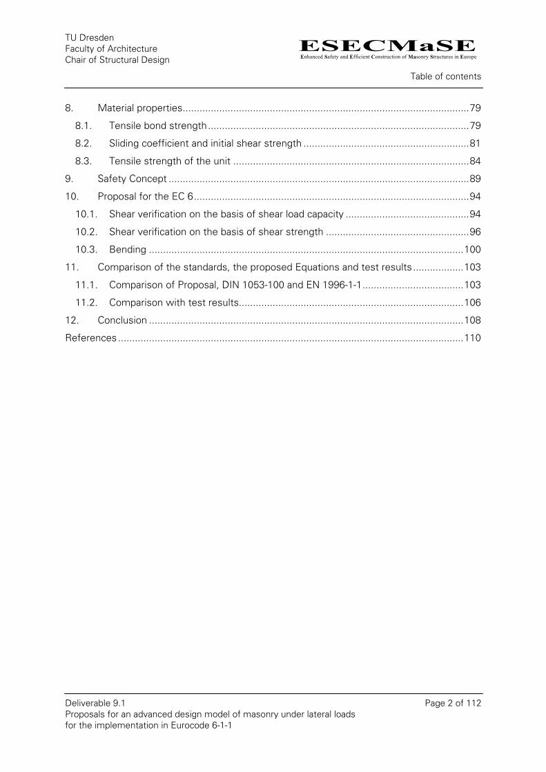
8. Material properties......................................................................................................79 8.1. Tensile bond strength.............................................................................................79 8.2. Sliding coefficient and initial shear strength ...........................................................81 8.3. Tensile strength of the unit ....................................................................................84
9. Safety Concept ...........................................................................................................89 10. Proposal for the EC 6..................................................................................................94
10.1. Shear verification on the basis of shear load capacity ............................................94 10.2. Shear verification on the basis of shear strength ...................................................96 10.3. Bending ................................................................................................................100
11. Comparison of the standards, the proposed Equations and test results..................103 11.1. Comparison of Proposal, DIN 1053-100 and EN 1996-1-1....................................103 11.2. Comparison with test results................................................................................106
12. Conclusion ................................................................................................................108 References ...........................................................................................................................110
ESECMaSEEnhanced Safety and Efficient Construction of Masonry Structures in Europe
TU Dresden Faculty of Architecture Chair of Structural Design
Introduction
Deliverable 9.1 Page 3 of 112 Proposals for an advanced design model of masonry under lateral loads for the implementation in Eurocode 6-1-1
1. Introduction
The research project ESECMaSE has already lead to new knowledge about shear behaviour
of masonry. This includes the results of the tests which were already carried out, the
analytical and numerical studies and their comparison with the available experimental
results. While the theoretical considerations were concentrated mainly on the static loading,
the experimental implementation has been investigating the behaviour under cyclic loading
too. The static loading can be seen as a special case of the cyclic loading.
The intention of this report is to collect the results about the shear behaviour under static
loading for the purpose to propose an advanced design model of masonry subject to lateral
loads for the implementation in Eurocode 6-1-1 (EC6). Therefore some already introduced or
proposed normative regulations are taken as examples and thereupon compared with the
analytical consideration from Work Package 4 and the proposed shear design model. The
background of this proposal will be discussed and the universality will be checked.
Because of the major influence of the acting vertical load on the shear load capacity, this
issue will also be discussed and a proposal for implementation in the code will be made.
Within the scope of ESECMaSE the parameters of the used material were determined by
means of small tests. As a result, the large scale experiments can be understood and
recalculated. These values are of particular interest especially for the numerical recalculation.
But the amount of the material data is not large enough for an universal definition of material
properties for the normative work. A consideration of the already regulated normative values
as well as values from the literature will be made.
In addition, the governing equations will have to be expand by the safety factors and
compared with the collection of test results. This is necessary in order to ensure the global
safety standards.
Finally, a text proposal for a future update of the Eurocode 6-1-1 will be given, merely a basis
for discussion. The establishment of standards is a continually evolving process and the
evaluation of the pending tests will be reflected in it.
ESECMaSEEnhanced Safety and Efficient Construction of Masonry Structures in Europe
TU Dresden Faculty of Architecture Chair of Structural Design
State of standardisation
Deliverable 9.1 Page 4 of 112 Proposals for an advanced design model of masonry under lateral loads for the implementation in Eurocode 6-1-1
2. State of standardisation
Most of the masonry codes define in first place the shear strength and maybe propose an
equation for the calculation of the shear capacity of the wall in the second place. The
strength is thereby defined as the minimum value of strength, due to different failure
criteria. The main failure criterion, which is included in all standards, is the sliding. The
second criterion follows from the tensile strength of the unit.
The geometry and the mechanical behaviour of the whole wall have to be taken into account
by the designing engineer. This includes the absence of a tensile strength of masonry in
vertical direction, or the neglecting of it, which leads to the formation of gaps and a partially
compressed area. Other verification procedures, like the one for bending and compression,
have also to been performed. The shear part of the standards usually does not refer to them.
In the following some normative regulations of the design procedure for shear are listed.
Further procedures, like the Swiss or the Canadian approach are part of Deliverable 4.2 [12].
2.1. Australian Standard (AS 3700)
As an example of other non-European masonry standard the Australian Standard [1] should
be cited.
The verification of unreinforced masonry members for shear forces has to be satisfied for
each combination under minimum design compressive stress.
10 VVVd +≤ (1)
For AAC-masonry:
10 AAd VVV +≤ (2)
With
dwms AfV '0 φ= (3)
dwdv AfkV =1 (4)
butA AfV '0 67,0 φ= (5)
ESECMaSEEnhanced Safety and Efficient Construction of Masonry Structures in Europe
TU Dresden Faculty of Architecture Chair of Structural Design
State of standardisation
Deliverable 9.1 Page 5 of 112 Proposals for an advanced design model of masonry under lateral loads for the implementation in Eurocode 6-1-1
bdvA AfkV 1 = (6)
Or in short notation:
( ) dwdvmsd AfkfV +≤ ' φ (7)
For AAC-masonry:
( ) bdvutd AfkfV 67,0 ' +≤ φ (8)
Where:
kv is the shear factor (friction coefficient);
'msf is the characteristic shear strength of masonry;
Adw is the combined bedded area and grout area, if any, of a shear-resisting;
portion of a member; for members of solid rectangular cross-section;
fd the minimum design compressive stress on the bed joint under
consideration but not greater than 2 MPa;
Ab the bedded area of a masonry cross-section;
φ the capacity reduction factor;
'utf the characteristic lateral modulus of rupture of masonry units.
ESECMaSEEnhanced Safety and Efficient Construction of Masonry Structures in Europe
TU Dresden Faculty of Architecture Chair of Structural Design
State of standardisation
Deliverable 9.1 Page 6 of 112 Proposals for an advanced design model of masonry under lateral loads for the implementation in Eurocode 6-1-1
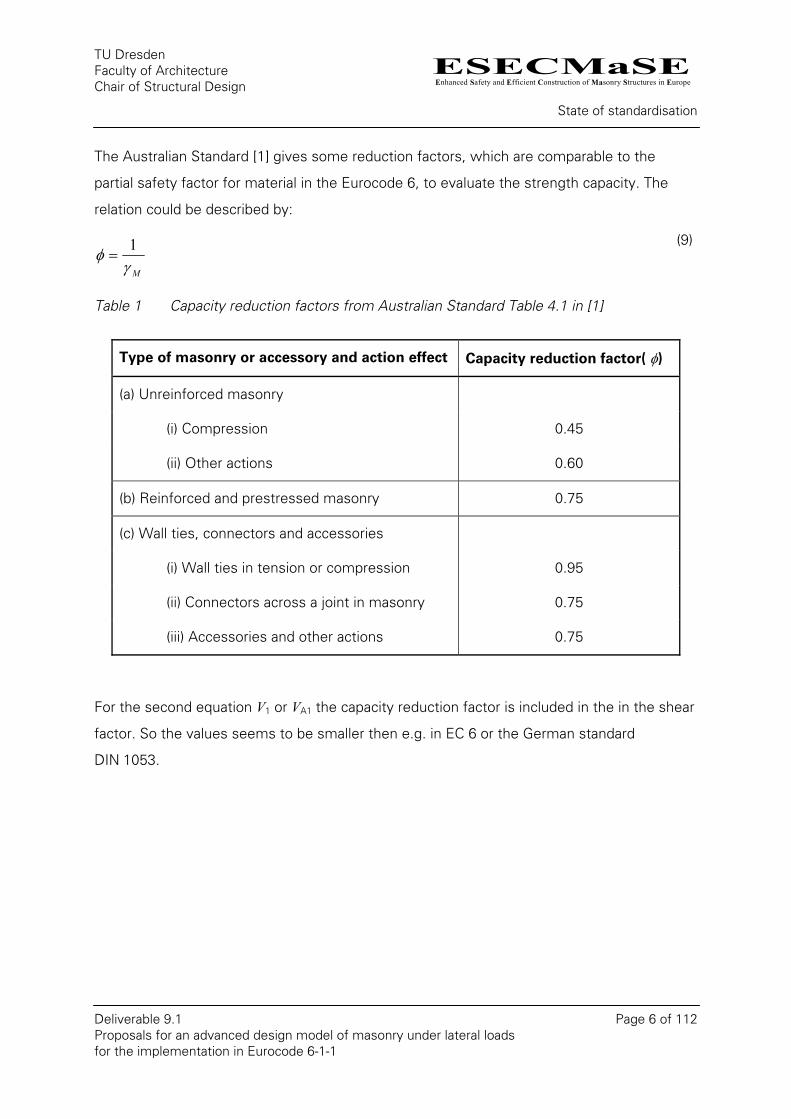
The Australian Standard [1] gives some reduction factors, which are comparable to the
partial safety factor for material in the Eurocode 6, to evaluate the strength capacity. The
relation could be described by:
Mγφ 1
= (9)
Table 1 Capacity reduction factors from Australian Standard Table 4.1 in [1]
Type of masonry or accessory and action effect Capacity reduction factor( φ)
(a) Unreinforced masonry
(i) Compression 0.45
(ii) Other actions 0.60
(b) Reinforced and prestressed masonry 0.75
(c) Wall ties, connectors and accessories
(i) Wall ties in tension or compression 0.95
(ii) Connectors across a joint in masonry 0.75
(iii) Accessories and other actions 0.75
For the second equation V1 or VA1 the capacity reduction factor is included in the in the shear
factor. So the values seems to be smaller then e.g. in EC 6 or the German standard
DIN 1053.

ESECMaSEEnhanced Safety and Efficient Construction of Masonry Structures in Europe
TU Dresden Faculty of Architecture Chair of Structural Design
State of standardisation
Deliverable 9.1 Page 7 of 112 Proposals for an advanced design model of masonry under lateral loads for the implementation in Eurocode 6-1-1
Table 2 Shear factors (friction coefficients) from the Australian Standard Table 3.3 in [1]
Type of masonry Location kv
Clay, concrete or
calcium silicate
At mortar bed joints 0.3
AAC At mortar bed joints 0.12
At membrane-type damp-proof courses, flashings and
similar locations where the membrane is in contact with
the unit, concrete or within the mortar and the damp-
proof course membrane is of—
(b) polyethylene-and-bitumen coated aluminium 0.15
(a) bitumen-coated aluminium or embossed polyethylene 0.3
At interface of masonry with concrete 0.3
At interface of masonry with steel 0.2
All
At other locations zero
In chapter 1.5.2.9 of the Australian Standard [1] the lateral modulus of rupture is descript as:
“The characteristic lateral modulus of rupture of masonry units ( ) is the characteristic
value of the flexural tensile strength of the masonry unit obtained when subjected to
bending in the direction normal to the plane of the wall. In the absence of test data, the
value of ( ) is not allowed to exceed 0.8 MPa.”
'utf
'utf
The characteristic shear strength is defined in 3.3.4 of the Australian Standard [1]. For
membrane-type damp-proof courses, flashings, it should be zero, or an appropriate value
based on the results of tests. For shear in the horizontal direction in continuous horizontal
mortar joints, for masonry constructed of other than AAC units, a value of
( = characteristic flexural tensile strength) but not greater than 0.35 MPa, nor less than
'msf
'25.1 mtf⋅
'mtf
ESECMaSEEnhanced Safety and Efficient Construction of Masonry Structures in Europe
TU Dresden Faculty of Architecture Chair of Structural Design
State of standardisation
Deliverable 9.1 Page 8 of 112 Proposals for an advanced design model of masonry under lateral loads for the implementation in Eurocode 6-1-1
0.15 MPa. At a joint or interface confined by bonded reinforcement normal to the shear
plane 0.35 MPa.
The Australian Standard [1] gives also values for the vertical direction.
2.2. Eurocode 6 (EN 1996-1-1)
The Eurocode 6 [5] is a joint development of some member states of the European Union.
The intention is to unify the normative regulations for Europe. Therefore European
committees were established to develop a proposal which has to be ratified by the national
consortiums. The current version of the EC 6 could be used parallel to the national
standards. The national standards will be entirely replaced in long-term.
A special feature of the Eurocode is the considering of country construction methods or
building material properties. For this purpose possibilities were inserted at the appropriate
points in the standardization text for national definitions. The concretions have to be made in
the respective national annexes. Within a certain scope dissent design rules could also be
define.
In chapter 6.2 of the Eurocode 6 [5] the verification of unreinforced masonry walls subjected
to shear loading is regulated. At the ultimate limit state the design value of the shear load
applied to the masonry wall, VEd, shall be less than or equal to the design value of the shear
resistance of the wall, VRd.
RdEd VV ≤ (10)
The design value of the shear load has to be calculated in accordance to EN 1990 or
DIN 1055-100. Typically it based on a characteristic loads multiplied by combination value and
partial safety factors.
The design value of the shear resistance is given by:
tlfV cvdRd = (11)
Where:
fvd is the design value of the shear strength of masonry, based on the average of the vertical stresses over the compressed part of the wall that is providing the shear resistance;

ESECMaSEEnhanced Safety and Efficient Construction of Masonry Structures in Europe
TU Dresden Faculty of Architecture Chair of Structural Design
State of standardisation
Deliverable 9.1 Page 9 of 112 Proposals for an advanced design model of masonry under lateral loads for the implementation in Eurocode 6-1-1
t is the thickness of the wall resisting the shear;
lc is the length of the compressed part of the wall, ignoring any part of the wall that is in tension. The length of the compressed part of the wall, lc, should be calculated assuming a linear stress distribution of the compressive stresses.
The design value of the shear strength of masonry hast to be calculated by:
M
vkvd
ff
γ=
(12)
In the Eurocode 6 [5] in section 3.6.2 (1) as a binding definition is written: “The characteristic
shear strength of masonry, fvk, shall be determined from the results of tests on masonry”.
As a second source for the shear strength a database could be used. But it is also possible
to calculate the shear strength. For these the EC 6 has foreseen the following equation:
dvkvk ff σ4,00 += (13)
Where:
fvko is the characteristic initial shear strength, under zero compressive stress;
The initial shear strength fvko have to be halve for unfilled perpend joint.
fvlt is a limit to the value of fvk;
σd is the design compressive stress perpendicular to the shear in the member at the
level under consideration, using the appropriate load combination based on the
average vertical stress over the compressed part of the wall that is providing shear
resistance;
fb is the normalised compressive strength of the masonry units, as described in 3.1.2.1
of EC 6, for the direction of application of the load on the test specimens being
perpendicular to the bed face.
For the tensile failure of the unit an upper limit of 0,065 fb or 0,045 fb for unfilled perpend
joints is given. Instead of theses limit a value fvlt could be defined in the National Annex of
every country. Herewith it should be possible to take other effects into account e.g. a
special influence of the tensile strength of the units and/or of the overlap in the masonry.
ESECMaSEEnhanced Safety and Efficient Construction of Masonry Structures in Europe
TU Dresden Faculty of Architecture Chair of Structural Design
State of standardisation
Deliverable 9.1 Page 10 of 112 Proposals for an advanced design model of masonry under lateral loads for the implementation in Eurocode 6-1-1
In shell bedded masonry, where the units are bedded on two or more equal strips of general
purpose mortar, the initial shear strength fvko has to be reduced by the relation of the width
of the stripes to the width of the wall.
The initial shear strength of the masonry may be determined from either tests, like the
characteristic shear strength, or from the values given in table 3.4 in EC 6 [5]. When a
country decides to determine its values of fvko from a database, the values may be found in
the National Annex.
ESECMaSEEnhanced Safety and Efficient Construction of Masonry Structures in Europe
TU Dresden Faculty of Architecture Chair of Structural Design
State of standardisation
Deliverable 9.1 Page 11 of 112 Proposals for an advanced design model of masonry under lateral loads for the implementation in Eurocode 6-1-1
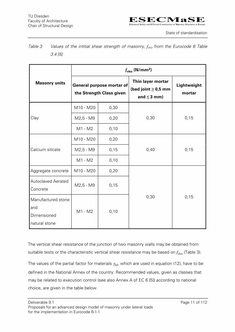
Table 3 Values of the intitial shear strength of masonry, fvko from the Eurocode 6 Table
3.4 [5]
fvko (N/mm2)
Masonry units General purpose mortar of
the Strength Class given
Thin layer mortar
(bed joint ≥ 0,5 mm
and ≤ 3 mm)
Lightweight
mortar
M10 - M20 0,30
M2,5 - M9 0,20 Clay
M1 - M2 0,10
0,30 0,15
M10 - M20 0,20
M2,5 - M9 0,15 Calcium silicate
M1 - M2 0,10
0,40 0,15
Aggregate concrete M10 - M20 0,20
Autoclaved Aerated
Concrete M2,5 - M9 0,15
Manufactured stone
and
Dimensioned
natural stone
M1 - M2 0,10
0,30 0,15
The vertical shear resistance of the junction of two masonry walls may be obtained from
suitable tests or the characteristic vertical shear resistance may be based on fvko (Table 3).
The values of the partial factor for materials γM, which are used in equation (12), have to be
defined in the National Annex of the country. Recommended values, given as classes that
may be related to execution control (see also Annex A of EC 6 [5]) according to national
choice, are given in the table below.
ESECMaSEEnhanced Safety and Efficient Construction of Masonry Structures in Europe
TU Dresden Faculty of Architecture Chair of Structural Design
State of standardisation
Deliverable 9.1 Page 12 of 112 Proposals for an advanced design model of masonry under lateral loads for the implementation in Eurocode 6-1-1
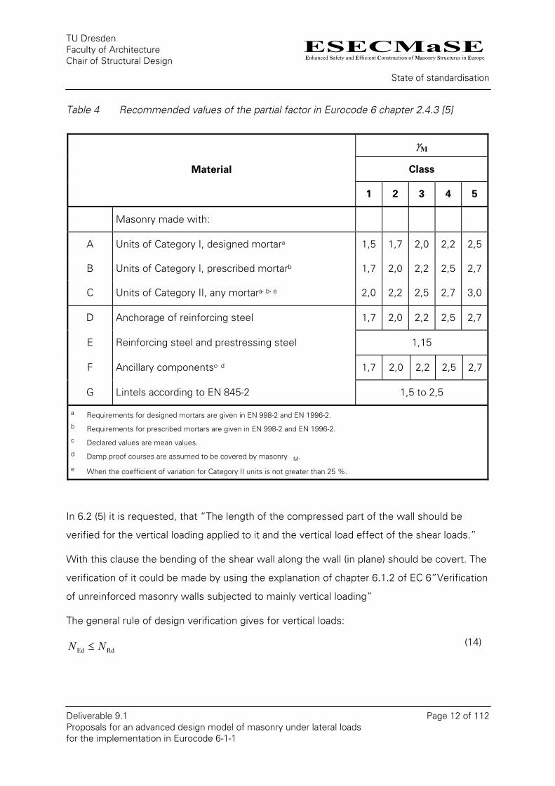
Table 4 Recommended values of the partial factor in Eurocode 6 chapter 2.4.3 [5]
γM
Class Material
1 2 3 4 5
Masonry made with:
A Units of Category I, designed mortara 1,5 1,7 2,0 2,2 2,5
B Units of Category I, prescribed mortarb 1,7 2,0 2,2 2,5 2,7
C Units of Category II, any mortara, b, e 2,0 2,2 2,5 2,7 3,0
D Anchorage of reinforcing steel 1,7 2,0 2,2 2,5 2,7
E Reinforcing steel and prestressing steel 1,15
F Ancillary componentsc, d 1,7 2,0 2,2 2,5 2,7
G Lintels according to EN 845-2 1,5 to 2,5
a Requirements for designed mortars are given in EN 998-2 and EN 1996-2. b Requirements for prescribed mortars are given in EN 998-2 and EN 1996-2. c Declared values are mean values. d Damp proof courses are assumed to be covered by masonry �M.
e When the coefficient of variation for Category II units is not greater than 25 %.
In 6.2 (5) it is requested, that “The length of the compressed part of the wall should be
verified for the vertical loading applied to it and the vertical load effect of the shear loads.”
With this clause the bending of the shear wall along the wall (in plane) should be covert. The
verification of it could be made by using the explanation of chapter 6.1.2 of EC 6”Verification
of unreinforced masonry walls subjected to mainly vertical loading”
The general rule of design verification gives for vertical loads:
RdEd NN ≤ (14)
ESECMaSEEnhanced Safety and Efficient Construction of Masonry Structures in Europe
TU Dresden Faculty of Architecture Chair of Structural Design
State of standardisation
Deliverable 9.1 Page 13 of 112 Proposals for an advanced design model of masonry under lateral loads for the implementation in Eurocode 6-1-1
The design value of the vertical resistance is given by:
dRd ftN Φ= (15)
Where:
Φ is the capacity reduction factor, φi, at the top or bottom of the wall, or φm, in the middle of the wall, as appropriate, allowing for the effects of slenderness and eccentricity of loading;
t is the thickness of the wall;
fd is the design compressive strength of the masonry.
In case of the verification of shear walls in plane the reduction factor φ without the
slenderness effect should be used. This is equals to φi at the top or bottom of the wall.
Therefore the EC 6 suggests a rectangular stress block for the verification.
tei
i 21 −=Φ (16)
The EC 6 has also the opportunity to verify low eccentric loads by using the bending tensile
strength. For this the strength has to be defined by experiments or can be found in the
tables mentioned in the notes.
ESECMaSEEnhanced Safety and Efficient Construction of Masonry Structures in Europe
TU Dresden Faculty of Architecture Chair of Structural Design
State of standardisation
Deliverable 9.1 Page 14 of 112 Proposals for an advanced design model of masonry under lateral loads for the implementation in Eurocode 6-1-1
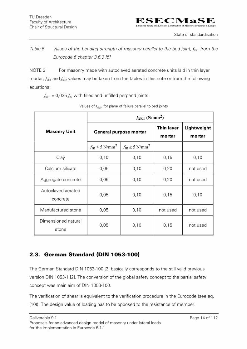
Table 5 Values of the bending strength of masonry parallel to the bed joint, fxk1 from the
Eurocode 6 chapter 3.6.3 [5]
NOTE 3 For masonry made with autoclaved aerated concrete units laid in thin layer
mortar, fxk1 and fxk2 values may be taken from the tables in this note or from the following
equations:
fxk1 = 0,035 fb, with filled and unfilled perpend joints
Values of fxk1, for plane of failure parallel to bed joints
fxk1 (N/mm2)
General purpose mortar Thin layer
mortar
Lightweight
mortar Masonry Unit
fm < 5 N/mm2 fm ≥ 5 N/mm2
Clay 0,10 0,10 0,15 0,10
Calcium silicate 0,05 0,10 0,20 not used
Aggregate concrete 0,05 0,10 0,20 not used
Autoclaved aerated
concrete 0,05 0,10 0,15 0,10
Manufactured stone 0,05 0,10 not used not used
Dimensioned natural
stone 0,05 0,10 0,15 not used
2.3. German Standard (DIN 1053-100)
The German Standard DIN 1053-100 [3] basically corresponds to the still valid previous
version DIN 1053-1 [2]. The conversion of the global safety concept to the partial safety
concept was main aim of DIN 1053-100.
The verification of shear is equivalent to the verification procedure in the Eurocode (see eq.
(10)). The design value of loading has to be opposed to the resistance of member.
ESECMaSEEnhanced Safety and Efficient Construction of Masonry Structures in Europe
TU Dresden Faculty of Architecture Chair of Structural Design
State of standardisation
Deliverable 9.1 Page 15 of 112 Proposals for an advanced design model of masonry under lateral loads for the implementation in Eurocode 6-1-1
The design factor of the applied shear loading has to be defined on the basis of the semi
probabilistic safety concept according to the information in EN 1990. Furthermore the
vertical loading must be considered due to its positive effect with the partial safety factor of
γE = 1.0 to calculate the load capacity.
The design value of the shear load resistance VRd results from:
cdf
VM
vksRd ⋅=
γα (17)
Where:
fvk is the characteristic shear strength;
γM is the partial safety factor for the material;
αs is the coefficient of the shear capacity. For the verification of shear walls under wind
load it is considered to be αs = 1,125 l or αs = 1.333 lc whereas the minor of both
values is decisive. In all other cases αs = l and αs = lc respectively must be applied.
l is the length the verifiable wall;
lc is the length the compressed part of the wall, ignoring any part of the wall that is in
tension;
d is the thickness of the verifiable wall;
c is the factor to consider the shear stress distribution over the cross section.
Der Faktor für die Berücksichtigung der Schubspannungsverteilung in der Wand ist nur in
den deutschen Normen DIN 1053-1 bzw. DIN 1053-100 enthalten. Er ist in Abhängigkeit von
der Wandgeometrie wie folgt zu bestimmt:
Only the German standard DIN 1053-1 and DIN 1053-100 respectively include the factor to
consider the distribution of the shear stress along a wall. The factor must be defined
depending on the geometry of the wall as follows:
c = 1,0 for hw/l ≤ 1
c = 1,5 for hw/l ≥ 2.
(18)
ESECMaSEEnhanced Safety and Efficient Construction of Masonry Structures in Europe
TU Dresden Faculty of Architecture Chair of Structural Design
State of standardisation
Deliverable 9.1 Page 16 of 112 Proposals for an advanced design model of masonry under lateral loads for the implementation in Eurocode 6-1-1
Where:
hw is the height of the wall;
l is the length of the wall.
Intermediate values must be interpolated linearly.
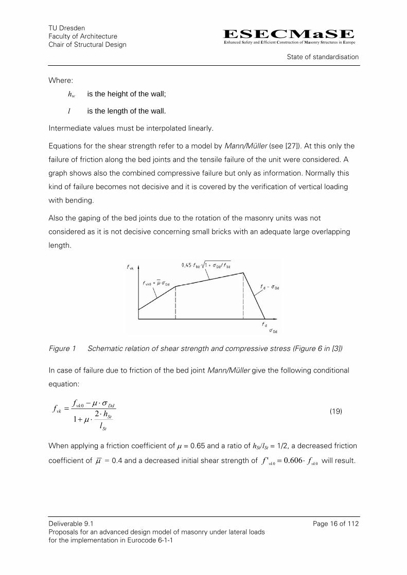
Equations for the shear strength refer to a model by Mann/Müller (see [27]). At this only the
failure of friction along the bed joints and the tensile failure of the unit were considered. A
graph shows also the combined compressive failure but only as information. Normally this
kind of failure becomes not decisive and it is covered by the verification of vertical loading
with bending.
Also the gaping of the bed joints due to the rotation of the masonry units was not
considered as it is not decisive concerning small bricks with an adequate large overlapping
length.
Figure 1 Schematic relation of shear strength and compressive stress (Figure 6 in [3])
In case of failure due to friction of the bed joint Mann/Müller give the following conditional
equation:
St
St
Ddvkvk
lh
ff
⋅⋅+
⋅−=
21
0
µ
σµ (19)
When applying a friction coefficient of µ = 0.65 and a ratio of hSt/lSt = 1/2, a decreased friction
coefficient of µ = 0.4 and a decreased initial shear strength of 00 606.0' vkvk ff ⋅= will result.

ESECMaSEEnhanced Safety and Efficient Construction of Masonry Structures in Europe
TU Dresden Faculty of Architecture Chair of Structural Design
State of standardisation
Deliverable 9.1 Page 17 of 112 Proposals for an advanced design model of masonry under lateral loads for the implementation in Eurocode 6-1-1
Thus the following equation is applied, when verifying shear loading with the exact method
according to DIN 1053-100:
Ddvkvk ff σµ ⋅+′= 0 . (20)
Mann/Müller [27] derive the tensile failure of the unit from the first principal stress (tension)
in the middle of the unit. There a shear stress factor of 2.3 for the maximal shear stress in
the unit was considered. The resulting equation is::
bz
Ddbzvk f
ffσ
+= 145.0
(21)
The minor value in the equations (20) and (21) is decisive for the verification.
Where:
f´vk0 is the decreased initial shear strength according to Table 6;
µ is the decreased friction coefficient. The distribution of the stress in the bed joint along
a unit is considered by decreasing. 4,0=µ can be used for all types of mortar.
σDd is the design compressive stress at the location of the maximal shear stress;
fbz is the tensile strength of the unit. Using the following:
fbz = 0,025 ⋅ fbk for hollow bricks;
fbz = 0,033 ⋅ fbk for perforated bricks and units with grip holes or grip pockets;
fbz = 0,040 ⋅ fbk for bricks without grip holes or grip pockets;
fbk is the characteristical value for compressive strength of the unit (classification of the
unit’s strength).
ESECMaSEEnhanced Safety and Efficient Construction of Masonry Structures in Europe
TU Dresden Faculty of Architecture Chair of Structural Design
State of standardisation
Deliverable 9.1 Page 18 of 112 Proposals for an advanced design model of masonry under lateral loads for the implementation in Eurocode 6-1-1
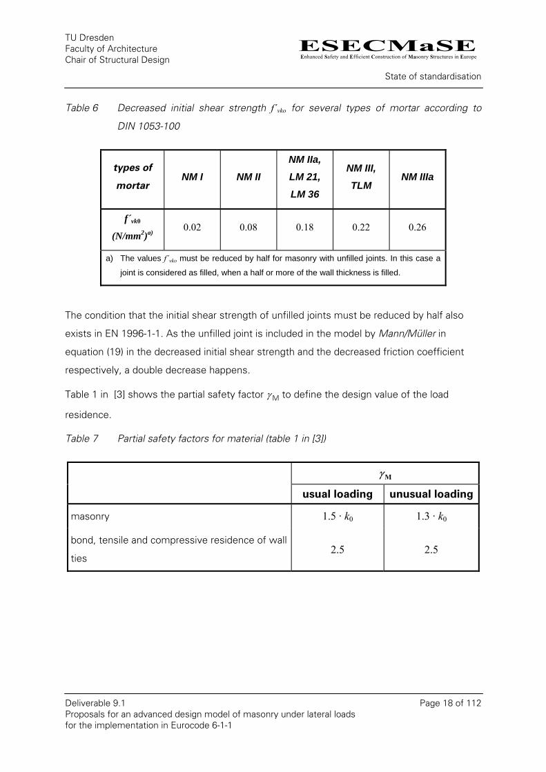
Table 6 Decreased initial shear strength f´vko for several types of mortar according to
DIN 1053-100
types of
mortar NM I NM II
NM IIa,
LM 21,
LM 36
NM III,
TLM NM IIIa
f´vk0
(N/mm2)a) 0.02 0.08 0.18 0.22 0.26
a) The values f´vko must be reduced by half for masonry with unfilled joints. In this case a
joint is considered as filled, when a half or more of the wall thickness is filled.
The condition that the initial shear strength of unfilled joints must be reduced by half also
exists in EN 1996-1-1. As the unfilled joint is included in the model by Mann/Müller in
equation (19) in the decreased initial shear strength and the decreased friction coefficient
respectively, a double decrease happens.
Table 1 in [3] shows the partial safety factor γ M to define the design value of the load
residence.
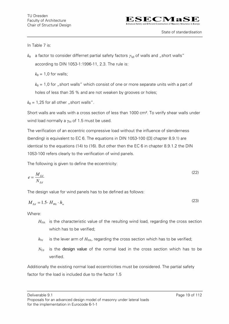
Table 7 Partial safety factors for material (table 1 in [3])
γ M
usual loading unusual loading
masonry 1.5 · k0 1.3 · k0
bond, tensile and compressive residence of wall
ties 2.5 2.5
ESECMaSEEnhanced Safety and Efficient Construction of Masonry Structures in Europe
TU Dresden Faculty of Architecture Chair of Structural Design
State of standardisation
Deliverable 9.1 Page 19 of 112 Proposals for an advanced design model of masonry under lateral loads for the implementation in Eurocode 6-1-1
In Table 7 is:
k0 a factor to consider differnet partial safety factors γ M of walls and „short walls“
according to DIN 1053-1:1996-11, 2.3. The rule is:
k0 = 1,0 for walls;
k0 = 1,0 for „short walls“ which consist of one or more separate units with a part of
holes of less than 35 % and are not weaken by grooves or holes;
k0 = 1,25 for all other „short walls“.
Short walls are walls with a cross section of less than 1000 cm². To verify shear walls under
wind load normally a γM of 1.5 must be used.
The verification of an eccentric compressive load without the influence of slenderness
(bending) is equivalent to EC 6. The equations in DIN 1053-100 ([3] chapter 8.9.1) are
identical to the equations (14) to (16). But other then the EC 6 in chapter 8.9.1.2 the DIN
1053-100 refers clearly to the verification of wind panels.
The following is given to define the eccentricity:
Ed
Ed
NM
e = (22)
The design value for wind panels has to be defined as follows:
wWkEd hHM ⋅⋅= 5.1 (23)
Where:
HWk is the characteristic value of the resulting wind load, regarding the cross section
which has to be verified;
hW is the lever arm of HWk, regarding the cross section which has to be verified;
NEd is the design value of the normal load in the cross section which has to be
verified.
Additionally the existing normal load eccentricities must be considered. The partial safety
factor for the load is included due to the factor 1.5
ESECMaSEEnhanced Safety and Efficient Construction of Masonry Structures in Europe
TU Dresden Faculty of Architecture Chair of Structural Design
State of standardisation
Deliverable 9.1 Page 20 of 112 Proposals for an advanced design model of masonry under lateral loads for the implementation in Eurocode 6-1-1
Besides it is necessary that the calculated strain at the tensile loaded side is not larger than
0.1‰ with eccentricities larger than l/6. Thus an uncracked cross section should be indirectly
ensured to take the initial shear strength into account for verifying friction at different
directions of loading. If it is not possible to verify the tensile strain for unusual load
combinations, the initial shear strength should be omitted when defining shear strength at
ultimate limit state.
2.4. Latest Proposal for DIN 1053
The analytical approach for shear was enhanced in Germany on the basis of the model of
Mann/Müller over the past years. Thus an addition for irregular bond (staircase bond) was
made by Simon [33]. Another essay about shear failure of large-sized masonry by
Jäger/Schöps [22] discusses the regular bond and facture behaviour with partial failure of the
joints. As it is verified experimentally and numerically that failure in case of tensile failure of
the unit begins at the kerb of the unit, a new equation for unit failure was developed as well.
The extended proposal for shear strength was discussed for the German standard and the
national annex of the European masonry code. In the following a short description should be
given.
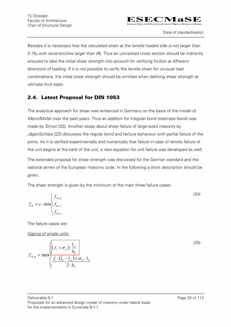
The shear strength is given by the minimum of the main three failure cases:
⎪⎩
⎪⎨
⎧
⋅=
uvk
fvk
gvk
vk
f
f
f
cf
,
,
,
min
(24)
The failure cases are:
Gaping of single units
( )
( )⎪⎪⎩
⎪⎪⎨
⎧
⋅⋅+−⋅
⋅+
=
b
bdolbt
b
oldt
gvk
hlllf
hl
ff
2
max, σ
σ
(25)
ESECMaSEEnhanced Safety and Efficient Construction of Masonry Structures in Europe
TU Dresden Faculty of Architecture Chair of Structural Design
State of standardisation
Deliverable 9.1 Page 21 of 112 Proposals for an advanced design model of masonry under lateral loads for the implementation in Eurocode 6-1-1
Where:
ft is the characteristic initial shear strength. For masonry made of general purpose
mortar and light weight mortar ft = 0,05 N/mm² and for masonry of thin layer mortar
ft = 0,15 N/mm² should be applied;
σd is the design compressive stress at the location of the maximal shear stress;
lol is the overlapping length;
hb is the height of the brick;
lb is the length of the brick.
Friction failure
( )
⎪⎪⎪
⎩
⎪⎪⎪
⎨
⎧
⋅+⋅
−+
⋅+
=
db
olvk
olb
b
dvk
fvk
ll
f
llhσf
f
σµ
µ
µ
0
0
,
1max
(26)
Where:
fvk0 is the characteristic initial shear strength;
µ is the friction coefficient.
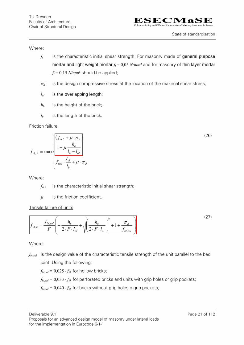
Tensile failure of units
⎟⎟⎟
⎠
⎞
⎜⎜⎜
⎝
⎛++⎟⎟
⎠
⎞⎜⎜⎝
⎛⋅⋅
+⋅⋅
−=calbt
d
ol
b
ol
bcalbtuvk flF
hlF
hF
ff
,
2,
, 122
σ
(27)
Where:
fbt,cal is the design value of the characteristic tensile strength of the unit parallel to the bed
joint. Using the following:
fbt,cal = 0,025 ⋅ fbk for hollow bricks;
fbt,cal = 0,033 ⋅ fbk for perforated bricks and units with grip holes or grip pockets;
fbt,cal = 0,040 ⋅ fbk for bricks without grip holes o grip pockets;

ESECMaSEEnhanced Safety and Efficient Construction of Masonry Structures in Europe
TU Dresden Faculty of Architecture Chair of Structural Design
State of standardisation
Deliverable 9.1 Page 22 of 112 Proposals for an advanced design model of masonry under lateral loads for the implementation in Eurocode 6-1-1
fbk is the characteristic compressive strength of the units (classification of the unit’s
strength according to DIN 1053-1);
F is the shear stress factor for the masonry unit. For masonry with a bed joint thickness
of 12 mm at least, F = 1.7, and in all other cases F = 2.3 should be used.
The theories provide also a combined failure for compression in combination with shear
stress. But this failure mode is covered by other effects, like buckling. Therefore it isn’t
needed for des design.
Through the standardisation process the decision was made to use only the red framed
equations and neglect the ductile effect in the standard. This restriction leads to assumption
of a total collapse due to the first local failure.
ESECMaSEEnhanced Safety and Efficient Construction of Masonry Structures in Europe
TU Dresden Faculty of Architecture Chair of Structural Design
Proposed Equation from Deliverable 4.3
Deliverable 9.1 Page 23 of 112 Proposals for an advanced design model of masonry under lateral loads for the implementation in Eurocode 6-1-1
3. Proposed Equation from Deliverable 4.3
Beside numerous tests in the context of the research project ESECMaSE some analytical
considerations about the shear load capacity were made in a subproject. A s a result of this
investigations Graubner/Kranzler proposed some equation in Deliverable 4.3 [19] and in [21].
The proposed equations are recapitulated in the following.
For failure due to bending it is proposed:
( )2
21 nnv
vbending −⋅
⋅=
λ
(28)
With:
flt
Nn⋅⋅
= is the standardized vertical force;
fltVv
⋅⋅= is the standardized horizontal capacity;
lh
v ⋅=ψλ is the shear slenderness;
ψ is a coefficient to describe the static system of the wall;
ψ = 1.0 for cantilever systems;
ψ = 0.5 for full fixed walls with full restraint at the top.
For failure due to gaping it is proposed:
⎟⎟⎠
⎞⎜⎜⎝
⎛+
⋅=
hhnl
vb
bgaping
112
(29)
ESECMaSEEnhanced Safety and Efficient Construction of Masonry Structures in Europe
TU Dresden Faculty of Architecture Chair of Structural Design
Proposed Equation from Deliverable 4.3
Deliverable 9.1 Page 24 of 112 Proposals for an advanced design model of masonry under lateral loads for the implementation in Eurocode 6-1-1
Where:
hb is the height of the masonry unit;
lb is the length of the masonry unit;
h is the height of the wall.
For sliding:
nv friction ⋅= µ (30)
Where:
µ is the friction coefficient.
For tensile failure of the unit it is proposed:
⎟⎟⎠
⎞⎜⎜⎝
⎛−
⋅++⋅⋅= C
fnkC
Ff
cv
btbtunitSJ 111 2
*,/
(31)
Where:
ol
b
lFh
C⋅⋅
= *2
⎟⎟⎠
⎞⎜⎜⎝
⎛⋅+⋅=
NmmfFF bt
2* 46.06325.0
F is the shear stress factor for the masonry unit; for thin layer mortar F = 2.0; for
general purpose mortar F = 1.7;
c is the factor to consider the shear stress distribution over the cross section
c ≤0.5+λv≤1.5;
k is a factor to take the distribution of the vertical stress in the cross-section into
account k = 1.05;
btf is the standardized tensile strength of the unit ff
f btbt = ;
lol is the overlapping length.
ESECMaSEEnhanced Safety and Efficient Construction of Masonry Structures in Europe
TU Dresden Faculty of Architecture Chair of Structural Design
Proposed Equation from Deliverable 4.3
Deliverable 9.1 Page 25 of 112 Proposals for an advanced design model of masonry under lateral loads for the implementation in Eurocode 6-1-1
After the verification with test results in [20] some verification were made.
Latest version from [21]:
( ) ( )⎟⎟⎟
⎠
⎞
⎜⎜⎜
⎝
⎛−⎟
⎟⎠
⎞⎜⎜⎝
⎛++⋅⋅=
− 1111
,
2*2*,
calbtcalbttensile f
nFFfc
v
(32)
Where:
fbt,cal is the splitting tensile strength for perforated units with more the 25% of holes;
in other cases the horizontal tensile strength should be used.
btfF 85.02.1* +=
For AAC:
( ) ( )⎟⎟⎟
⎠
⎞
⎜⎜⎜
⎝
⎛−⎟
⎟⎠
⎞⎜⎜⎝
⎛++⋅⋅⋅=
− 114
121
,
2*2*
,calbt
calbttensile fnFFf
cv
(33)
For the code a non-standardized notation should be used.
⎟⎟⎠
⎞⎜⎜⎝
⎛⋅⋅
−⋅⋅
=flt
NNVv
bending
2
21λ
(34)
⎟⎟⎠
⎞⎜⎜⎝
⎛+
⋅=
hhNl
Vb
bgaping
112
(35)
NV friction ⋅= µ (36)
( ) ( ) ⎟⎟
⎠
⎞
⎜⎜
⎝
⎛−⎟
⎟⎠
⎞⎜⎜⎝
⎛++⋅⋅⋅⋅=
− 1111
,
2*2*,
calbt
dcalbtunit f
FFtlfc
Vσ
(37)
( ) ( )⎟⎟
⎠
⎞
⎜⎜
⎝
⎛−⎟
⎟⎠
⎞⎜⎜⎝
⎛++⋅⋅⋅⋅⋅=
− 114
121
,
2*2*
,,calbt
dcalbtAACunit f
FFtlfc
Vσ
(38)
The main difference to existing standards is an added failure criterion. It described a
overturning of a unit strut. This one is still knows for many years and investigated in some
research projects. But for old masonry it was assumed as negligible due to the aspect ration.
ESECMaSEEnhanced Safety and Efficient Construction of Masonry Structures in Europe
TU Dresden Faculty of Architecture Chair of Structural Design
Proposed Equation from Deliverable 4.3
Deliverable 9.1 Page 26 of 112 Proposals for an advanced design model of masonry under lateral loads for the implementation in Eurocode 6-1-1
Within the new proposal no bonding strength is needed for calculation. This main
characteristic of these proposals makes the calculation for the load bearing capacities much
easier, because the loos of bonding strength due to opening of joints has no effect on the
calculated shear load capacity. But the shear load capacity will be underestimated for low
loaded walls.
ESECMaSEEnhanced Safety and Efficient Construction of Masonry Structures in Europe
TU Dresden Faculty of Architecture Chair of Structural Design
Comparison and discussion of the proposed equations
Deliverable 9.1 Page 27 of 112 Proposals for an advanced design model of masonry under lateral loads for the implementation in Eurocode 6-1-1
4. Comparison and discussion of the proposed equations
4.1. Bending
The verification of bending is included in all masonry standards. However, it normally relates
only to bending out of plane or for systems like beams. Therefore the stress block is the
basis for the design in EC 6 (see chapter 2.2). In DIN 1053-100 which also has the stress
block as basis, wind panels are clearly listed as an application.
The use of the stress block with masonry is not without controversy. The several stone-
mortar-combinations show a different behaviour in compressive experiments. A variety,
from ductile to very brittle, can be noticed there, which also presents the determined
strength-strain- relations in [12] and [13]. But the stress block shows an adequate
approximation for a failure in small ranges like the support of a slab. There is also no
differentiation between stress block and brittle material for the load capacity in case of a
centric loading of a cross section without influence of slenderness. The influence only
results from eccentric loading and larger compressed length. This applies to stiffening
panels. Is the compressive strength due to in-plane-bending reached in the whole
compressed part, the strain state at the external edges will be much higher than the failure
strain of the masonry.
Another special characteristic of stiffening walls is the superposition of compressive with
shear stress and respectively the resulting principal tensile stress. This can lead to an early
failure in the limiting part regarding bending compression in comparison to a pure bending
load.
As the bending failure mostly appear at the bottom or the upper wall edge in the region of
the load introduction from the slab, the differences of the stiffness between masonry and
reinforced concrete also have an influence. The reinforced concrete slab leads to a
restriction of transverse strain in the masonry. Through this a biaxial compressive stress
state in the masonry is built up, which leads to an increase of the load capacity. The slabs
ESECMaSEEnhanced Safety and Efficient Construction of Masonry Structures in Europe
TU Dresden Faculty of Architecture Chair of Structural Design
Comparison and discussion of the proposed equations
Deliverable 9.1 Page 28 of 112 Proposals for an advanced design model of masonry under lateral loads for the implementation in Eurocode 6-1-1
also cause a special load distribution, when e. g. small parts fail due to local material
inhomogeneity or rotation of units.
The above-mentioned effects partially cancel out each other. Figures 3-3 to 3-7 in [19] show
that with large shear slenderness. The shear load capacity of the numerical calculation lies
between the calculated under the assumption of a stress block and the one under the
assumption of a linear stress distribution. There the geometry of the unit has a minor
influence as the case may be (see Figure 3-3 wall D_6_K). It could actually lie below the
linear elastic approach using smaller shear slenderness (= longer walls).
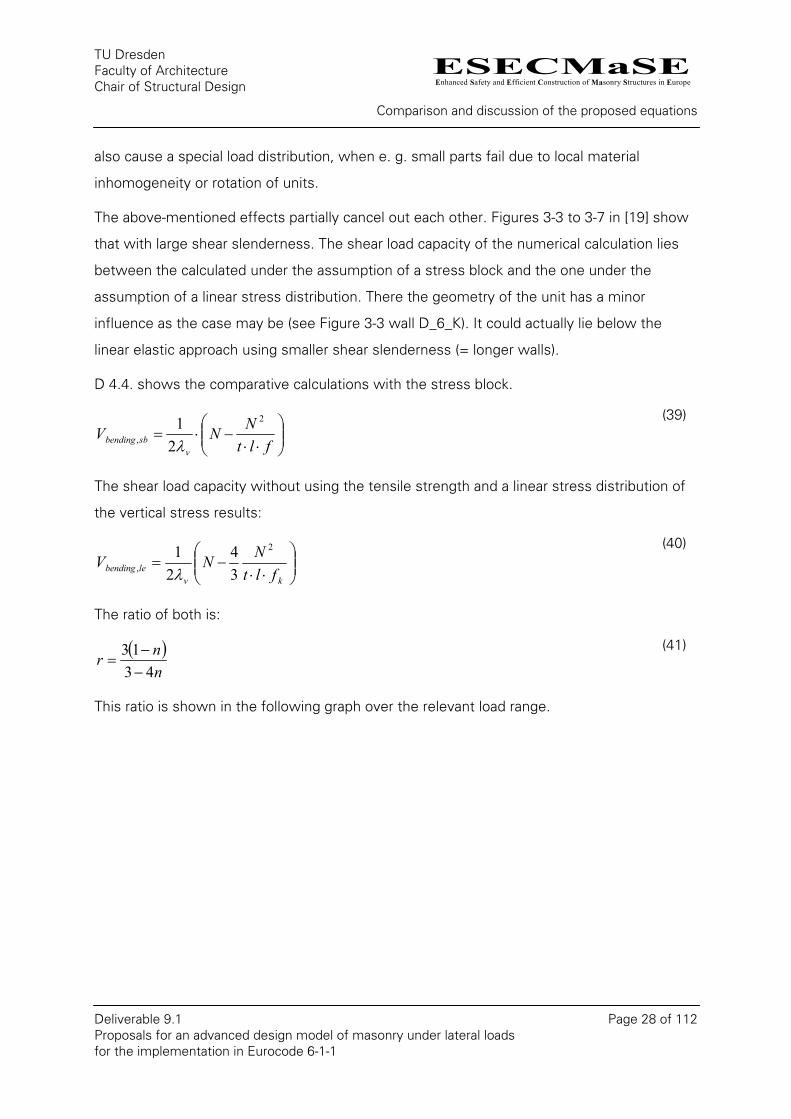
D 4.4. shows the comparative calculations with the stress block.
⎟⎟⎠
⎞⎜⎜⎝
⎛⋅⋅
−⋅=flt
NNVv
sbbending
2
, 21λ
(39)
The shear load capacity without using the tensile strength and a linear stress distribution of
the vertical stress results:
⎟⎟⎠
⎞⎜⎜⎝
⎛⋅⋅
−=kv
lebending fltNNV
2
, 34
21λ
(40)
The ratio of both is:
( )nnr
4313−−
= (41)
This ratio is shown in the following graph over the relevant load range.

ESECMaSEEnhanced Safety and Efficient Construction of Masonry Structures in Europe
TU Dresden Faculty of Architecture Chair of Structural Design
Comparison and discussion of the proposed equations
Deliverable 9.1 Page 29 of 112 Proposals for an advanced design model of masonry under lateral loads for the implementation in Eurocode 6-1-1
1
1.05
1.1
1.15
1.2
1.25
0 0.05 0.1 0.15 0.2 0.25 0.3 0.35n = N /(t l f k)
r
Figure 2 Ratio between the shear design loads due to bending calculated from the stress
block and linear elastic behaviour
For small loads up to n=0.2 the difference between stress block and linear material
behaviour is less then 10%. The use of stress blocks is here adequate.
As far as the design for bending under higher vertical loads only becomes important at large
slenderness (=short walls) compared to other types of failure, and as with these walls there
appears a ductile bending failure, the application of a stress blocks is an acceptable
compromise.
The 10 % reduction of the stress block in Eq. 3-17 which is proposed alternatively in [19]
would lead to a better correlation with the numerical results with smaller slenderness.
Another possibility to verify shear capacity of walls with low loads could be the use of the
tensile strength. This was already done in [23] to recalculate experiments. In this approach a
moment can be calculated using the following known equation (Navier) for the uncracked
cross section together with the maximal stress at the edge, with is equal to the tensile
strength.
ANz
IM
−⋅=σ (42)
ESECMaSEEnhanced Safety and Efficient Construction of Masonry Structures in Europe
TU Dresden Faculty of Architecture Chair of Structural Design
Comparison and discussion of the proposed equations
Deliverable 9.1 Page 30 of 112 Proposals for an advanced design model of masonry under lateral loads for the implementation in Eurocode 6-1-1
Were:
σ is the stress at the by z defined point of the cross section;
M is the moment;
I is the moment of inertia of the cross section;
z is the distance of a defined point from the centre of mass of the contributed
cross section where the stress should be calculated;
N is the normal load;
A is the contributed area of the cross section.
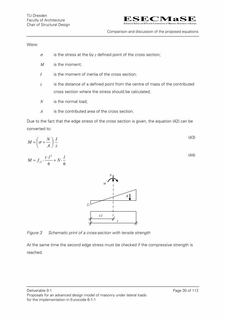
Due to the fact that the edge stress of the cross section is given, the equation (42) can be
converted to:
zI
ANM ⋅⎟
⎠⎞
⎜⎝⎛ += σ
(43)
66
2
1lNltfM x ⋅+
⋅⋅=
(44)
N
M
Figure 3 Schematic print of a cross-section with tensile strength
At the same time the second edge stress must be checked if the compressive strength is
reached.
l/2
l
R
fx1
ESECMaSEEnhanced Safety and Efficient Construction of Masonry Structures in Europe
TU Dresden Faculty of Architecture Chair of Structural Design
Comparison and discussion of the proposed equations
Deliverable 9.1 Page 31 of 112 Proposals for an advanced design model of masonry under lateral loads for the implementation in Eurocode 6-1-1
The shear load resistance can be calculated by the height of the wall and an existing
restraint if applicable.
v
xbending
NltfhMV
λψ ⋅+⋅⋅
=⋅
=6
13,
(45)
As from a defined load the bending load capacity of a cracked cross section (lx) is higher. For
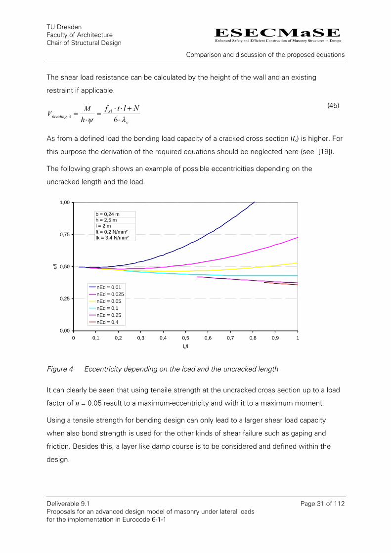
this purpose the derivation of the required equations should be neglected here (see [19]).
The following graph shows an example of possible eccentricities depending on the
uncracked length and the load.
0,00
0,25
0,50
0,75
1,00
0 0,1 0,2 0,3 0,4 0,5 0,6 0,7 0,8 0,9 1
lx/l
e/l
nEd = 0,01nEd = 0,025nEd = 0,05nEd = 0,1nEd = 0,25nEd = 0,4
b = 0,24 m
l = 2 mh = 2,5 m
ft = 0,2 N/mm²fk = 3,4 N/mm²
Figure 4 Eccentricity depending on the load and the uncracked length
It can clearly be seen that using tensile strength at the uncracked cross section up to a load
factor of n = 0.05 result to a maximum-eccentricity and with it to a maximum moment.
Using a tensile strength for bending design can only lead to a larger shear load capacity
when also bond strength is used for the other kinds of shear failure such as gaping and
friction. Besides this, a layer like damp course is to be considered and defined within the
design.
ESECMaSEEnhanced Safety and Efficient Construction of Masonry Structures in Europe
TU Dresden Faculty of Architecture Chair of Structural Design
Comparison and discussion of the proposed equations
Deliverable 9.1 Page 32 of 112 Proposals for an advanced design model of masonry under lateral loads for the implementation in Eurocode 6-1-1
If not considering tensile strength, the self-weight of a wall can already give the required
load for the shear load capacity.
For some of the tests which are summarised in [20] the measured shear load capacity is
larger than the overturning load. Recalculating is only possible when using tensile strength.
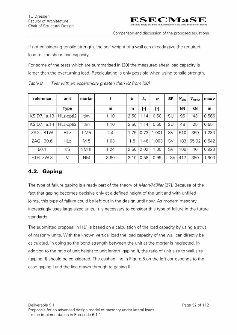
Table 8 Test with an eccentricity greaten then l/2 from [20]
reference unit mortar l h λv ψ SF Nobs VRTest max e
Type m m [-] [-] kN kN m
KS.D7.1a.13 HLz-opti2 tlm 1.10 2.50 1.14 0.50 SU 95 43 0.566
KS.D7.1a.14 HLz-opti2 tlm 1.10 2.50 1.14 0.50 SU 48 25 0.651
ZAG . BTW HLz LM5 2.4 1.75 0.73 1.001 SV 510 359 1.233
ZAG . 30.6 HLz M 5 1.03 1.5 1.46 1.003 SV 183 65.92 0.542
60.1 KS NM III 1.24 2.50 2.02 1.00 SV 109 40 0.920
ETH. ZW 3 V NM 3.60 2.10 0.58 0.99 t- SV 417 380 1.903
4.2. Gaping
The type of failure gaping is already part of the theory of Mann/Müller [27]. Because of the
fact that gaping becomes decisive only at a defined height of the unit and with unfilled
joints, this type of failure could be left out in the design until now. As modern masonry
increasingly uses large-sized units, it is necessary to consider this type of failure in the future
standards.
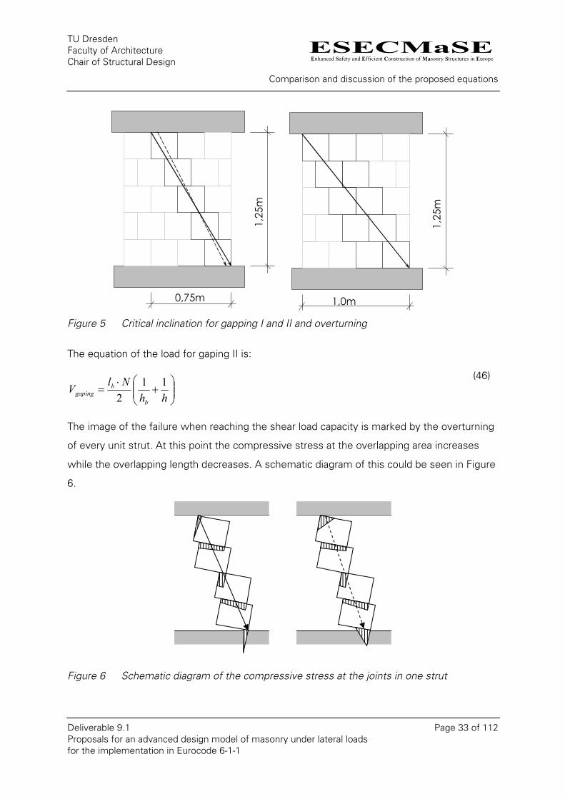
The submitted proposal in [19] is based on a calculation of the load capacity by using a strut
of masonry units. With the known vertical load the load capacity of the wall can directly be
calculated. In doing so the bond strength between the unit at the mortar is neglected. In
addition to the ratio of unit height to unit length (gaping I), the ratio of unit size to wall size
(gaping II) should be considered. The dashed line in Figure 5 on the left corresponds to the
case gaping I and the line drawn through to gaping II.
ESECMaSEEnhanced Safety and Efficient Construction of Masonry Structures in Europe
TU Dresden Faculty of Architecture Chair of Structural Design
Comparison and discussion of the proposed equations
Deliverable 9.1 Page 33 of 112 Proposals for an advanced design model of masonry under lateral loads for the implementation in Eurocode 6-1-1
0,75m
1,25
m
1,0m
1,25
m
Figure 5 Critical inclination for gapping I and II and overturning
The equation of the load for gaping II is:
⎟⎟⎠
⎞⎜⎜⎝
⎛+
⋅=
hhNlV
b
bgaping
112
(46)
The image of the failure when reaching the shear load capacity is marked by the overturning
of every unit strut. At this point the compressive stress at the overlapping area increases
while the overlapping length decreases. A schematic diagram of this could be seen in Figure
6.
Figure 6 Schematic diagram of the compressive stress at the joints in one strut
ESECMaSEEnhanced Safety and Efficient Construction of Masonry Structures in Europe
TU Dresden Faculty of Architecture Chair of Structural Design
Comparison and discussion of the proposed equations
Deliverable 9.1 Page 34 of 112 Proposals for an advanced design model of masonry under lateral loads for the implementation in Eurocode 6-1-1
At the first and at the last unit the stress peak becomes infinite for gapping II. This leads to a
local compressive failure with plasticity like a stress block. The real strut behaviour will be
somewhere between gapping I and II depending on the vertical load.
The proposed equations for gaping neglect the compression failure of each strut, but also
the bond strength.
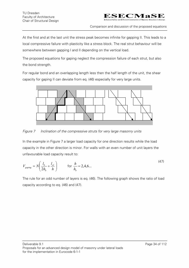
For regular bond and an overlapping length less then the half length of the unit, the shear
capacity for gaping II can deviate from eq. (46) especially for very large units.
Figure 7 Inclination of the compressive struts for very large masonry units
In the example in Figure 7 a larger load capacity for one direction results while the load
capacity in the other direction is minor. For walls with an even number of unit layers the
unfavourable load capacity result to:
⎟⎟⎠
⎞⎜⎜⎝
⎛+=
hl
hlNV ol
b
bgaping 2
for ...6,4,2=bh
h
(47)
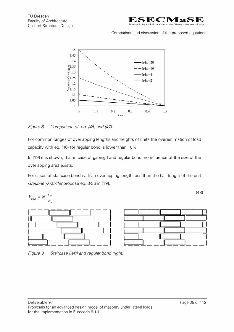
The rule for an odd number of layers is eq. (46). The following graph shows the ratio of load
capacity according to eq. (46) and (47).
ESECMaSEEnhanced Safety and Efficient Construction of Masonry Structures in Europe
TU Dresden Faculty of Architecture Chair of Structural Design
Comparison and discussion of the proposed equations
Deliverable 9.1 Page 35 of 112 Proposals for an advanced design model of masonry under lateral loads for the implementation in Eurocode 6-1-1
11.051.1
1.151.2
1.251.3
1.351.4
1.451.5
0 0.1 0.2 0.3 0.4 0.5l ol/l b
Vsy
mm
etry
/Vov
erla
ppin
g
h/hb=20
h/hb=10
h/hb=4
h/hb=2
Figure 8 Comparison of eq. (46) and (47)
For common ranges of overlapping lengths and heights of units the overestimation of load
capacity with eq. (46) for regular bond is lower than 10%
In [19] it is shown, that in case of gaping I and regular bond, no influence of the size of the
overlapping area exists.
For cases of staircase bond with an overlapping length less then the half length of the unit
Graubner/Kranzler propose eq. 3-36 in [19].
b
olIga h
lNV ⋅=, (48)
Figure 9 Staircase (left) and regular bond (right)
ESECMaSEEnhanced Safety and Efficient Construction of Masonry Structures in Europe
TU Dresden Faculty of Architecture Chair of Structural Design
Comparison and discussion of the proposed equations
Deliverable 9.1 Page 36 of 112 Proposals for an advanced design model of masonry under lateral loads for the implementation in Eurocode 6-1-1
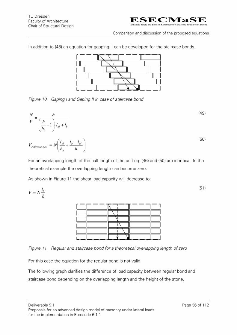
In addition to (48) an equation for gapping II can be developed for the staircase bonds.
Figure 10 Gaping I and Gaping II in case of staircase bond
bolb
llhh
hVN
+⋅⎟⎟⎠
⎞⎜⎜⎝
⎛−
=1
(49)
⎟⎟⎠
⎞⎜⎜⎝
⎛ −+=
hll
hl
NV olb
b
olgaIIstaircase,
(50)
For an overlapping length of the half length of the unit eq. (46) and (50) are identical. In the
theoretical example the overlapping length can become zero.
As shown in Figure 11 the shear load capacity will decrease to:
hlNV b=
(51)
Figure 11 Regular and staircase bond for a theoretical overlapping length of zero
For this case the equation for the regular bond is not valid.
The following graph clarifies the difference of load capacity between regular bond and
staircase bond depending on the overlapping length and the height of the stone.
ESECMaSEEnhanced Safety and Efficient Construction of Masonry Structures in Europe
TU Dresden Faculty of Architecture Chair of Structural Design
Comparison and discussion of the proposed equations
Deliverable 9.1 Page 37 of 112 Proposals for an advanced design model of masonry under lateral loads for the implementation in Eurocode 6-1-1
123456789
1011
0 0.1 0.2 0.3 0.4 0.5l ol/l b
Vre
gula
r /Vst
airc
ase
h/hb=20
h/hb=15
h/hb=10
h/hb=5
11.21.41.61.8
22.22.42.62.8
3
0.15 0.2 0.25 0.3 0.35 0.4 0.45 0.5l ol/l b
Vre
gula
r /Vst
airc
ase
h/hb=20
h/hb=15
h/hb=10
h/hb=5
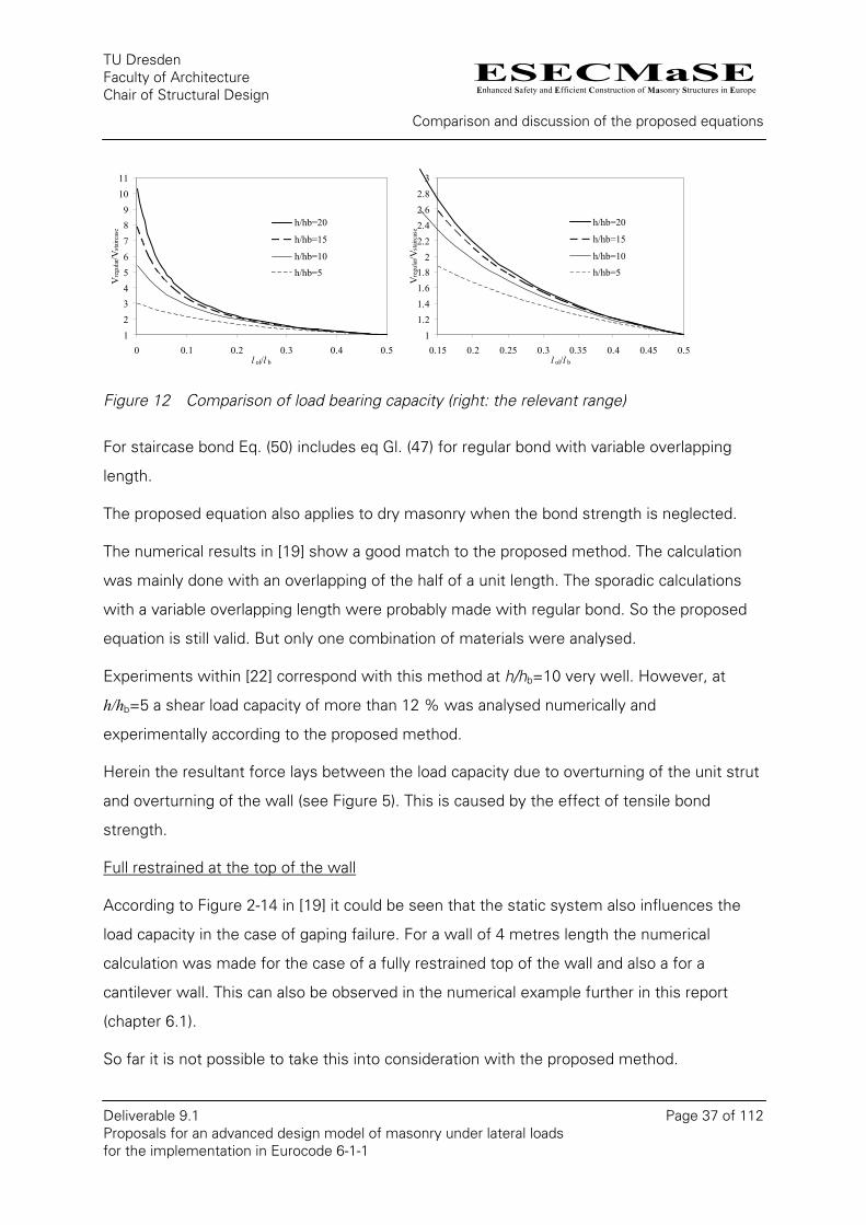
Figure 12 Comparison of load bearing capacity (right: the relevant range)
For staircase bond Eq. (50) includes eq Gl. (47) for regular bond with variable overlapping
length.
The proposed equation also applies to dry masonry when the bond strength is neglected.
The numerical results in [19] show a good match to the proposed method. The calculation
was mainly done with an overlapping of the half of a unit length. The sporadic calculations
with a variable overlapping length were probably made with regular bond. So the proposed
equation is still valid. But only one combination of materials were analysed.
Experiments within [22] correspond with this method at h/hb=10 very well. However, at
h/hb=5 a shear load capacity of more than 12 % was analysed numerically and
experimentally according to the proposed method.
Herein the resultant force lays between the load capacity due to overturning of the unit strut
and overturning of the wall (see Figure 5). This is caused by the effect of tensile bond
strength.
Full restrained at the top of the wall
According to Figure 2-14 in [19] it could be seen that the static system also influences the
load capacity in the case of gaping failure. For a wall of 4 metres length the numerical
calculation was made for the case of a fully restrained top of the wall and also a for a
cantilever wall. This can also be observed in the numerical example further in this report
(chapter 6.1).
So far it is not possible to take this into consideration with the proposed method.
ESECMaSEEnhanced Safety and Efficient Construction of Masonry Structures in Europe
TU Dresden Faculty of Architecture Chair of Structural Design
Comparison and discussion of the proposed equations
Deliverable 9.1 Page 38 of 112 Proposals for an advanced design model of masonry under lateral loads for the implementation in Eurocode 6-1-1
Verification on the basis of shear strength
Considering the tensile bond strength for the case of gaping failure is only possibly by using
the equation for shear strength instead equations for shear forces.
The equation by Mann/Müller [27] at gaping only considers masonry with an overlapping
length of the half length of a unit.
( )b
bdtvk h
lff
2σ+=
(52)
By Simon [33] it was extended by a variable overlapping length.
( )b
oldtvk h
lff σ+=
(53)
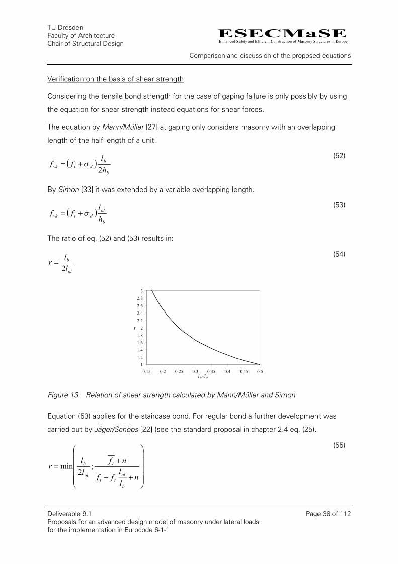
The ratio of eq. (52) and (53) results in:
ol
b
ll
r2
= (54)
11.2
1.41.61.8
2
2.22.42.6
2.83
0.15 0.2 0.25 0.3 0.35 0.4 0.45 0.5l ol /l b
r
Figure 13 Relation of shear strength calculated by Mann/Müller and Simon
Equation (53) applies for the staircase bond. For regular bond a further development was
carried out by Jäger/Schöps [22] (see the standard proposal in chapter 2.4 eq. (25).
⎟⎟⎟⎟⎟
⎠
⎞
⎜⎜⎜⎜⎜
⎝
⎛
+−
+=
nll
ff
nfll
r
b
oltt
t
ol
b ;2
min
(55)
ESECMaSEEnhanced Safety and Efficient Construction of Masonry Structures in Europe
TU Dresden Faculty of Architecture Chair of Structural Design
Comparison and discussion of the proposed equations
Deliverable 9.1 Page 39 of 112 Proposals for an advanced design model of masonry under lateral loads for the implementation in Eurocode 6-1-1
0.9
1
1.1
1.2
1.3
1.4
1.5
0.1 0.2 0.3 0.4 0.5l ol /l b
r
n=0n=0.05n=0.1n=0.15
0.9
1
1.1
1.2
1.3
1.4
1.5
0 0.05 0.1 0.15 0.2n = N /(t l f k )
r
lol/lb=0.15lol/lb=0.25lol/lb=0.33lol/lb=0.5
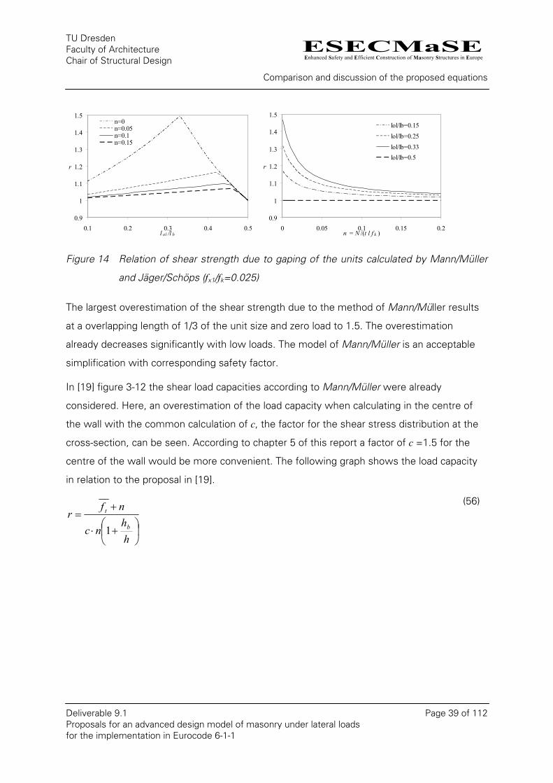
Figure 14 Relation of shear strength due to gaping of the units calculated by Mann/Müller
and Jäger/Schöps (fx1/fk=0.025)
The largest overestimation of the shear strength due to the method of Mann/Müller results
at a overlapping length of 1/3 of the unit size and zero load to 1.5. The overestimation
already decreases significantly with low loads. The model of Mann/Müller is an acceptable
simplification with corresponding safety factor.
In [19] figure 3-12 the shear load capacities according to Mann/Müller were already
considered. Here, an overestimation of the load capacity when calculating in the centre of
the wall with the common calculation of c, the factor for the shear stress distribution at the
cross-section, can be seen. According to chapter 5 of this report a factor of c =1.5 for the
centre of the wall would be more convenient. The following graph shows the load capacity
in relation to the proposal in [19].
⎟⎠
⎞⎜⎝
⎛+⋅
+=
hh
nc
nfr
b
t
1
(56)
ESECMaSEEnhanced Safety and Efficient Construction of Masonry Structures in Europe
TU Dresden Faculty of Architecture Chair of Structural Design
Comparison and discussion of the proposed equations
Deliverable 9.1 Page 40 of 112 Proposals for an advanced design model of masonry under lateral loads for the implementation in Eurocode 6-1-1
0.50.7
0.91.11.31.5
1.71.92.1
2.32.5
0 0.05 0.1 0.15 0.2n = N /(t l f k )
r
fx1/fk=0.1fx1/fk=0.075fx1/fk=0.05fx1/fk=0.025fx1/fk=0.01
0.50.70.91.11.31.51.71.92.12.32.5
0 0.05 0.1 0.15 0.2n = N /(t l f k )
r
h/hb=20h/hb=15h/hb=10h/hb=5
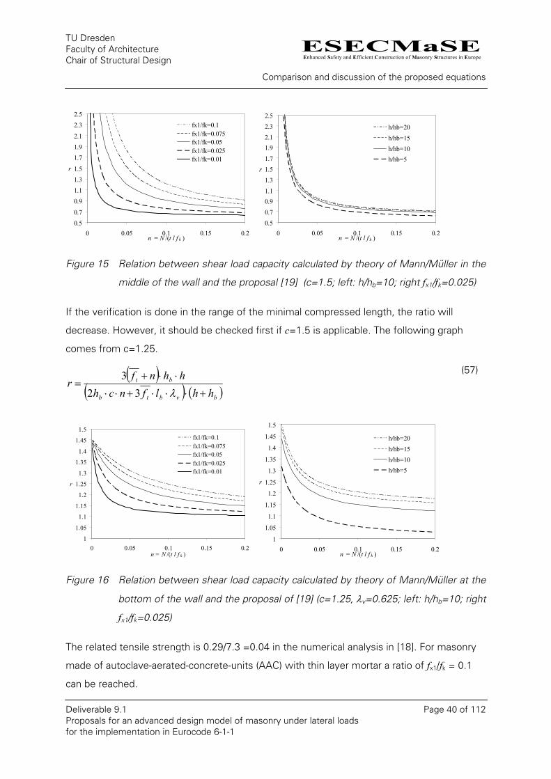
Figure 15 Relation between shear load capacity calculated by theory of Mann/Müller in the
middle of the wall and the proposal [19] (c=1.5; left: h/hb=10; right fx1/fk=0.025)
If the verification is done in the range of the minimal compressed length, the ratio will
decrease. However, it should be checked first if c=1.5 is applicable. The following graph
comes from c=1.25.
( )( ) ( )bvbtb
bt
hhlfnchhhnf
r+⋅⋅⋅+⋅⋅
⋅⋅+=
λ323
(57)
1
1.05
1.1
1.15
1.2
1.25
1.3
1.35
1.4
1.45
1.5
0 0.05 0.1 0.15 0.2n = N /(t l f k )
r
fx1/fk=0.1fx1/fk=0.075fx1/fk=0.05fx1/fk=0.025fx1/fk=0.01
1
1.05
1.1
1.15
1.2
1.25
1.3
1.35
1.4
1.45
1.5
0 0.05 0.1 0.15 0.2n = N /(t l f k )
r
h/hb=20h/hb=15h/hb=10h/hb=5
Figure 16 Relation between shear load capacity calculated by theory of Mann/Müller at the
bottom of the wall and the proposal of [19] (c=1.25, λv=0.625; left: h/hb=10; right
fx1/fk=0.025)
The related tensile strength is 0.29/7.3 =0.04 in the numerical analysis in [18]. For masonry
made of autoclave-aerated-concrete-units (AAC) with thin layer mortar a ratio of fx1/fk = 0.1
can be reached.
ESECMaSEEnhanced Safety and Efficient Construction of Masonry Structures in Europe
TU Dresden Faculty of Architecture Chair of Structural Design
Comparison and discussion of the proposed equations
Deliverable 9.1 Page 41 of 112 Proposals for an advanced design model of masonry under lateral loads for the implementation in Eurocode 6-1-1
The reduction of the tensile strength in shear by stress peaks in the range of the head joints
must be considered with a corresponding decrease (if applicable due to partial safety factor).
But specific analyses are still necessary to define the variables.
The approach of Mann/Müller does not completely apply to the range of the slabs. The
parabolic shear stress distribution according to the bending theory can not completely arise
in this range. For this, further theoretical analysis for the failure model and the factor c need
to be done.
Considering tensile bond strength for the gaping failure is a necessary base for considering
tensile strength for the bending verification. Otherwise the bending verification for walls
without load gives a certain shear load capacity but due to the verification of gaping, a load
cannot be applied.
4.3. Friction
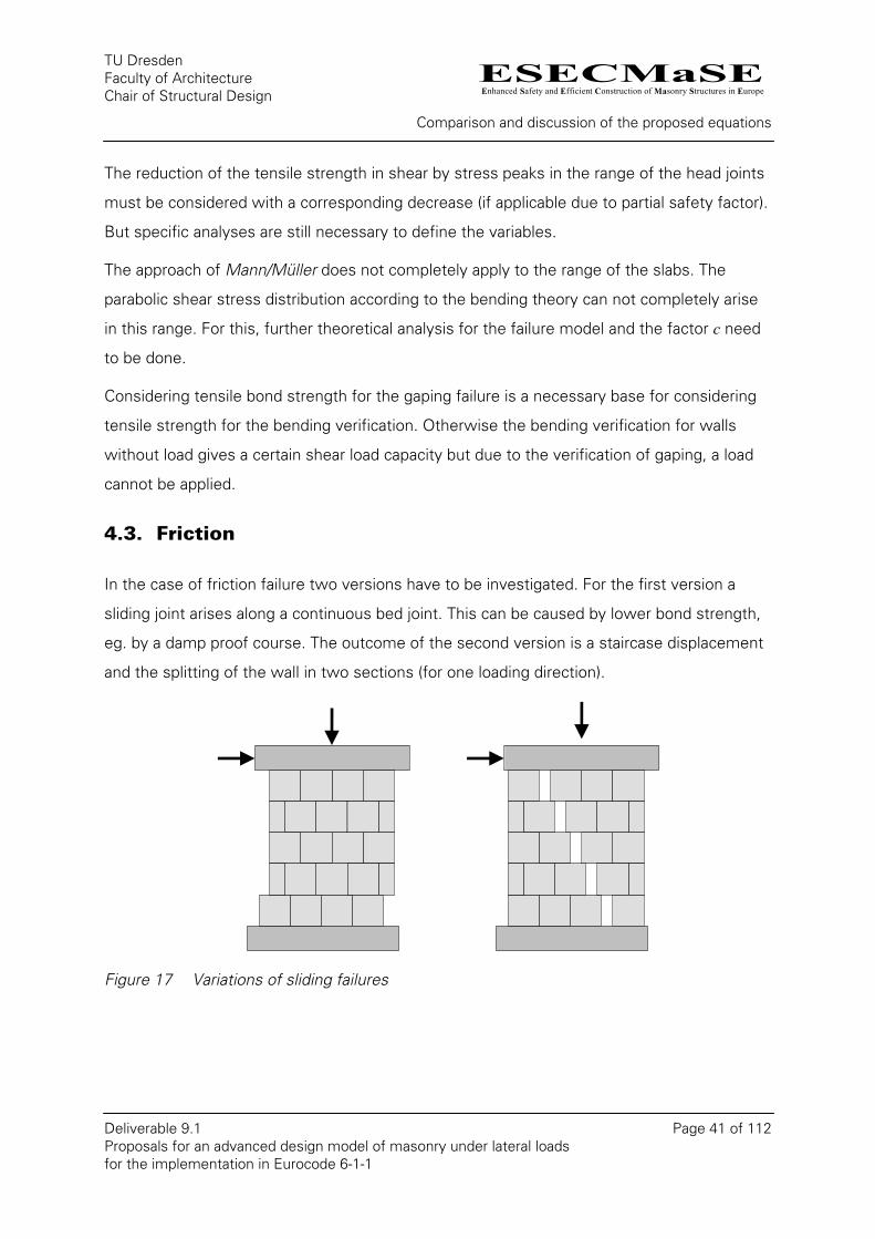
In the case of friction failure two versions have to be investigated. For the first version a
sliding joint arises along a continuous bed joint. This can be caused by lower bond strength,
eg. by a damp proof course. The outcome of the second version is a staircase displacement
and the splitting of the wall in two sections (for one loading direction).
Figure 17 Variations of sliding failures
ESECMaSEEnhanced Safety and Efficient Construction of Masonry Structures in Europe
TU Dresden Faculty of Architecture Chair of Structural Design
Comparison and discussion of the proposed equations
Deliverable 9.1 Page 42 of 112 Proposals for an advanced design model of masonry under lateral loads for the implementation in Eurocode 6-1-1
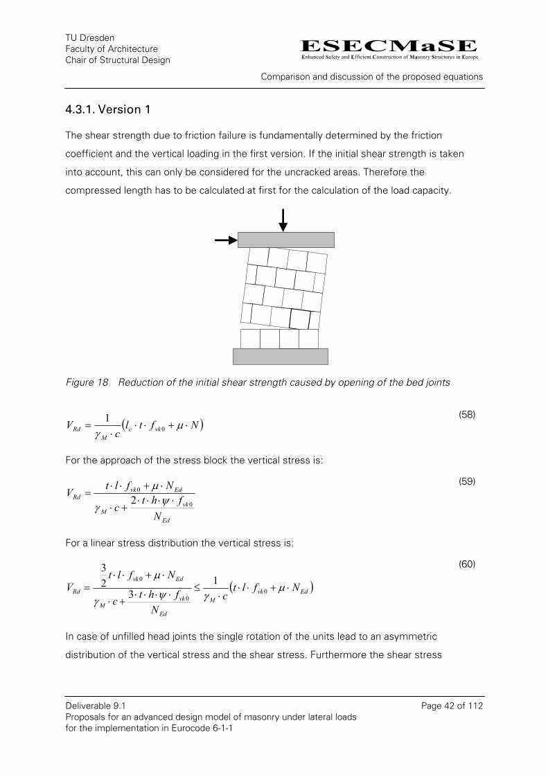
4.3.1. Version 1
The shear strength due to friction failure is fundamentally determined by the friction
coefficient and the vertical loading in the first version. If the initial shear strength is taken
into account, this can only be considered for the uncracked areas. Therefore the
compressed length has to be calculated at first for the calculation of the load capacity.
Figure 18 Reduction of the initial shear strength caused by opening of the bed joints
( )Nftlc
V vkcM
Rd ⋅+⋅⋅⋅
= µγ 0
1
(58)
For the approach of the stress block the vertical stress is:
Ed
vkM
EdvkRd
Nfht
c
NfltV
0
0
2 ⋅⋅⋅⋅+⋅
⋅+⋅⋅=
ψγ
µ
(59)
For a linear stress distribution the vertical stress is:
( )EdvkM
Ed
vkM
Edvk
Rd Nfltc
Nfhtc
NfltV ⋅+⋅⋅
⋅≤
⋅⋅⋅⋅+⋅
⋅+⋅⋅= µ
γψγ
µ0
0
0 13
23
(60)
In case of unfilled head joints the single rotation of the units lead to an asymmetric
distribution of the vertical stress and the shear stress. Furthermore the shear stress
ESECMaSEEnhanced Safety and Efficient Construction of Masonry Structures in Europe
TU Dresden Faculty of Architecture Chair of Structural Design
Comparison and discussion of the proposed equations
Deliverable 9.1 Page 43 of 112 Proposals for an advanced design model of masonry under lateral loads for the implementation in Eurocode 6-1-1
distribution of the wall is not equal to the distribution of the shear strength. This fact has to
be considered with the shear stress factor c.
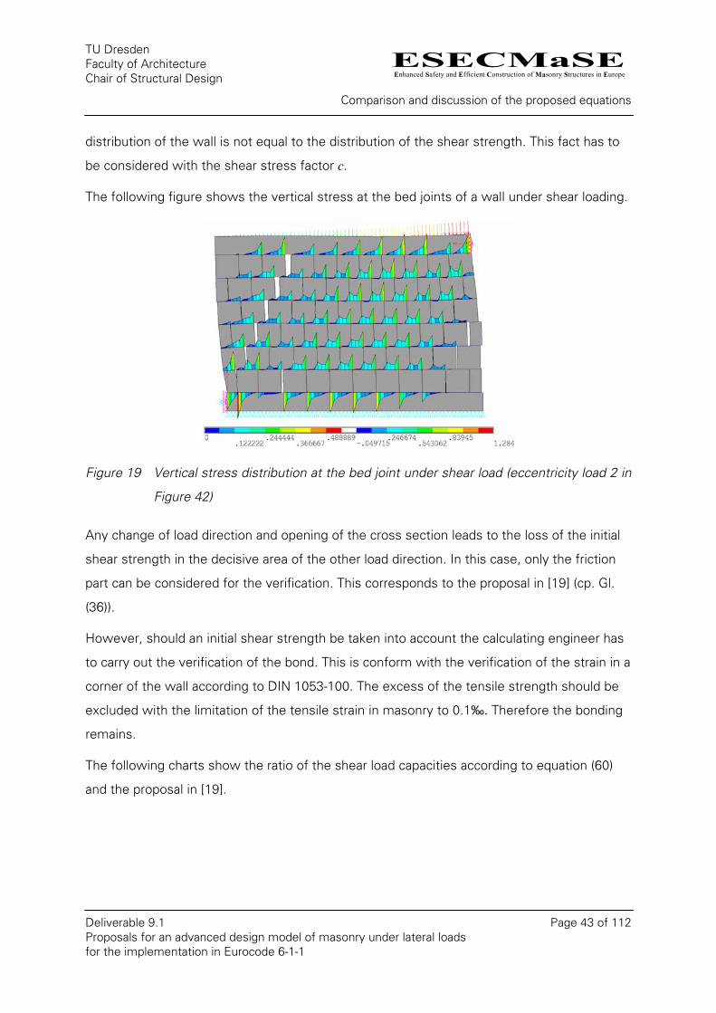
The following figure shows the vertical stress at the bed joints of a wall under shear loading.
Figure 19 Vertical stress distribution at the bed joint under shear load (eccentricity load 2 in
Figure 42)
Any change of load direction and opening of the cross section leads to the loss of the initial
shear strength in the decisive area of the other load direction. In this case, only the friction
part can be considered for the verification. This corresponds to the proposal in [19] (cp. Gl.
(36)).
However, should an initial shear strength be taken into account the calculating engineer has
to carry out the verification of the bond. This is conform with the verification of the strain in a
corner of the wall according to DIN 1053-100. The excess of the tensile strength should be
excluded with the limitation of the tensile strain in masonry to 0.1‰. Therefore the bonding
remains.
The following charts show the ratio of the shear load capacities according to equation (60)
and the proposal in [19].
ESECMaSEEnhanced Safety and Efficient Construction of Masonry Structures in Europe
TU Dresden Faculty of Architecture Chair of Structural Design
Comparison and discussion of the proposed equations
Deliverable 9.1 Page 44 of 112 Proposals for an advanced design model of masonry under lateral loads for the implementation in Eurocode 6-1-1
0.5
1
1.5
2
2.5
3
3.5
0 0.05 0.1 0.15 0.2n = N /(t l f k )
r
λ=0.25
λ=0.5
λ=0.75
λ=1
0.5
0.7
0.9
1.1
1.3
1.5
1.7
1.9
0 0.05 0.1 0.15 0.2n = N /(t l f k )
r
fvk0/fk=0.1fvk0/fk=0.075fvk0/fk=0.05fvk0/fk=0.025fvk0/fk=0.01
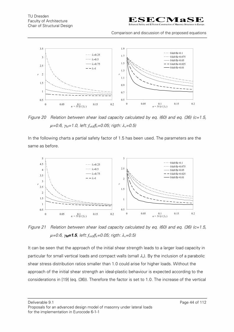
Figure 20 Relation between shear load capacity calculated by eq. (60) and eq. (36) (c=1.5,
µ=0.6, γM=1.0, left: fvk0/fk=0.05; rigth: λv=0.5)
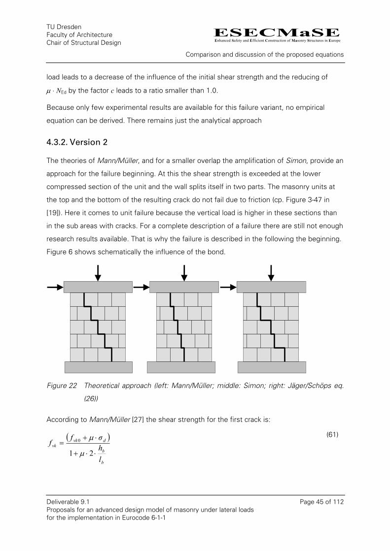
In the following charts a partial safety factor of 1.5 has been used. The parameters are the
same as before.
0.5
1
1.5
2
2.5
3
3.5
4
4.5
5
0 0.05 0.1 0.15 0.2n = N /(t l f k )
r
λ=0.25
λ=0.5
λ=0.75
λ=1
0.5
1
1.5
2
2.5
3
0 0.05 0.1 0.15 0.2n = N /(t l f k )
r
fvk0/fk=0.1fvk0/fk=0.075fvk0/fk=0.05fvk0/fk=0.025fvk0/fk=0.01
Figure 21 Relation between shear load capacity calculated by eq. (60) and eq. (36) (c=1.5,
µ=0.6, γM=1.5, left: fvk0/fk=0.05; rigth: λv=0.5)
It can be seen that the approach of the initial shear strength leads to a larger load capacity in
particular for small vertical loads and compact walls (small λv). By the inclusion of a parabolic
shear stress distribution ratios smaller than 1.0 could arise for higher loads. Without the
approach of the initial shear strength an ideal-plastic behaviour is expected according to the
considerations in [19] (eq. (36)). Therefore the factor is set to 1.0. The increase of the vertical
ESECMaSEEnhanced Safety and Efficient Construction of Masonry Structures in Europe
TU Dresden Faculty of Architecture Chair of Structural Design
Comparison and discussion of the proposed equations
Deliverable 9.1 Page 45 of 112 Proposals for an advanced design model of masonry under lateral loads for the implementation in Eurocode 6-1-1
load leads to a decrease of the influence of the initial shear strength and the reducing of
µ · NEd by the factor c leads to a ratio smaller than 1.0.
Because only few experimental results are available for this failure variant, no empirical
equation can be derived. There remains just the analytical approach
4.3.2. Version 2
The theories of Mann/Müller, and for a smaller overlap the amplification of Simon, provide an
approach for the failure beginning. At this the shear strength is exceeded at the lower
compressed section of the unit and the wall splits itself in two parts. The masonry units at
the top and the bottom of the resulting crack do not fail due to friction (cp. Figure 3-47 in
[19]). Here it comes to unit failure because the vertical load is higher in these sections than
in the sub areas with cracks. For a complete description of a failure there are still not enough
research results available. That is why the failure is described in the following the beginning.
Figure 6 shows schematically the influence of the bond.
Figure 22 Theoretical approach (left: Mann/Müller; middle: Simon; right: Jäger/Schöps eq.
(26))
According to Mann/Müller [27] the shear strength for the first crack is:
( )
b
b
dvkvk
lhσf
f⋅⋅+
⋅+=
21
0
µ
µ
(61)
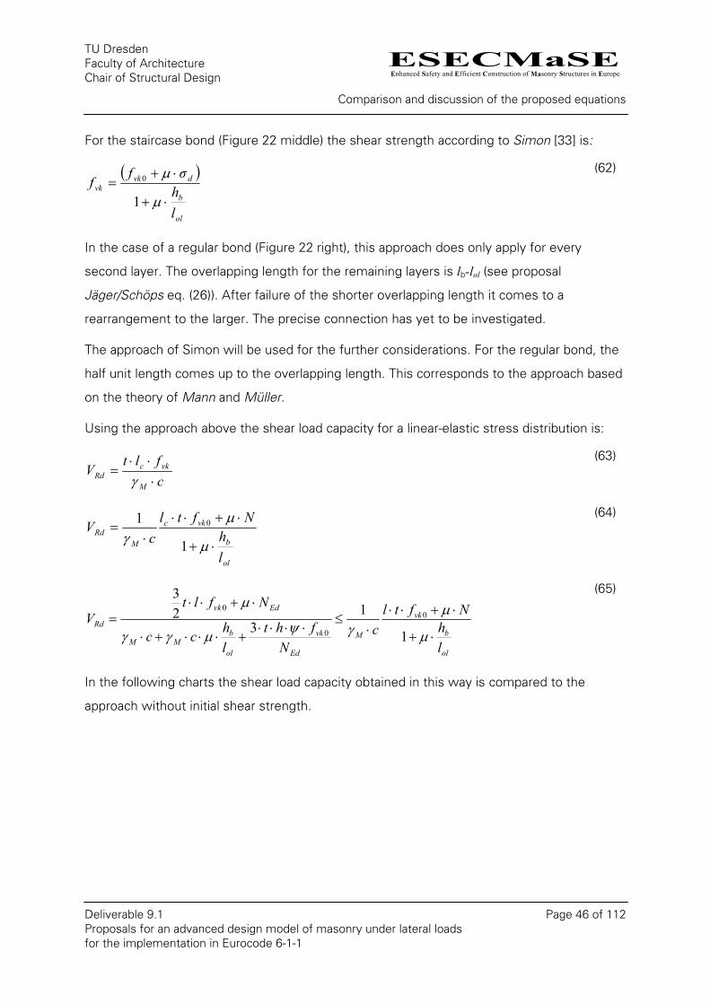
ESECMaSEEnhanced Safety and Efficient Construction of Masonry Structures in Europe
TU Dresden Faculty of Architecture Chair of Structural Design
Comparison and discussion of the proposed equations
Deliverable 9.1 Page 46 of 112 Proposals for an advanced design model of masonry under lateral loads for the implementation in Eurocode 6-1-1
For the staircase bond (Figure 22 middle) the shear strength according to Simon [33] is:
( )
ol
b
dvkvk
lhσf
f⋅+
⋅+=
µ
µ
1
0 (62)
In the case of a regular bond (Figure 22 right), this approach does only apply for every
second layer. The overlapping length for the remaining layers is lb-lol (see proposal
Jäger/Schöps eq. (26)). After failure of the shorter overlapping length it comes to a
rearrangement to the larger. The precise connection has yet to be investigated.
The approach of Simon will be used for the further considerations. For the regular bond, the
half unit length comes up to the overlapping length. This corresponds to the approach based
on the theory of Mann and Müller.
Using the approach above the shear load capacity for a linear-elastic stress distribution is:
cflt
VM
vkcRd ⋅
⋅⋅=
γ
(63)
ol
b
vkc
MRd
lh
Nftlc
V⋅+
⋅+⋅⋅⋅
=µ
µγ 1
1 0 (64)
ol
b
vk
M
Ed
vk
ol
bMM
Edvk
Rd
lh
Nftlc
Nfht
lhcc
NfltV
⋅+
⋅+⋅⋅⋅
≤⋅⋅⋅⋅
+⋅⋅⋅+⋅
⋅+⋅⋅=
µ
µγψµγγ
µ
1
13
23
0
0
0
(65)
In the following charts the shear load capacity obtained in this way is compared to the
approach without initial shear strength.
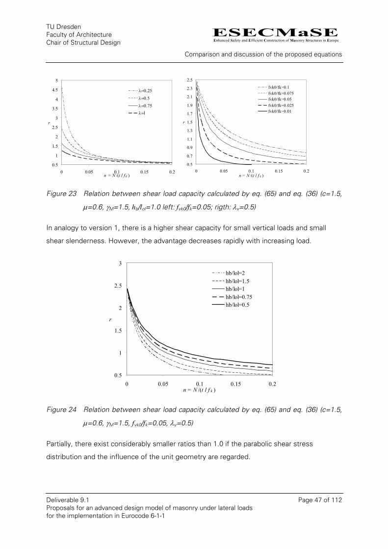
ESECMaSEEnhanced Safety and Efficient Construction of Masonry Structures in Europe
TU Dresden Faculty of Architecture Chair of Structural Design
Comparison and discussion of the proposed equations
Deliverable 9.1 Page 47 of 112 Proposals for an advanced design model of masonry under lateral loads for the implementation in Eurocode 6-1-1
0.5
1
1.5
2
2.5
3
3.5
4
4.5
5
0 0.05 0.1 0.15 0.2n = N /(t l f k )
r
λ=0.25
λ=0.5
λ=0.75
λ=1
0.5
0.7
0.9
1.1
1.3
1.5
1.7
1.9
2.1
2.3
2.5
0 0.05 0.1 0.15 0.2n = N /(t l f k )
r
fvk0/fk=0.1fvk0/fk=0.075fvk0/fk=0.05fvk0/fk=0.025fvk0/fk=0.01
Figure 23 Relation between shear load capacity calculated by eq. (65) and eq. (36) (c=1.5,
µ=0.6, γM=1.5, hb/lol=1.0 left: fvk0/fk=0.05; rigth: λv=0.5)
In analogy to version 1, there is a higher shear capacity for small vertical loads and small
shear slenderness. However, the advantage decreases rapidly with increasing load.
0.5
1
1.5
2
2.5
3
0 0.05 0.1 0.15 0.2n = N /(t l f k )
r
hb/lol=2hb/lol=1.5hb/lol=1hb/lol=0.75hb/lol=0.5
Figure 24 Relation between shear load capacity calculated by eq. (65) and eq. (36) (c=1.5,
µ=0.6, γM=1.5, fvk0/fk=0.05, λv=0.5)
Partially, there exist considerably smaller ratios than 1.0 if the parabolic shear stress
distribution and the influence of the unit geometry are regarded.
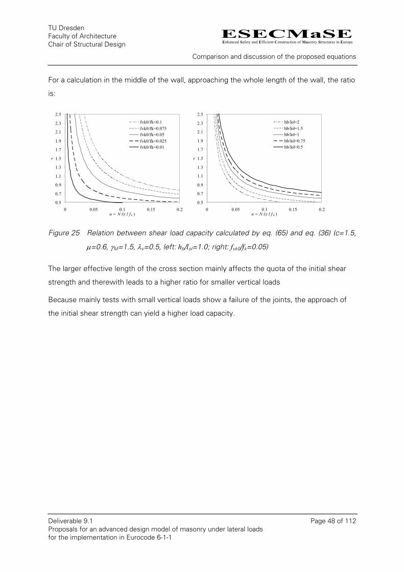
ESECMaSEEnhanced Safety and Efficient Construction of Masonry Structures in Europe
TU Dresden Faculty of Architecture Chair of Structural Design
Comparison and discussion of the proposed equations
Deliverable 9.1 Page 48 of 112 Proposals for an advanced design model of masonry under lateral loads for the implementation in Eurocode 6-1-1
For a calculation in the middle of the wall, approaching the whole length of the wall, the ratio
is:
0.5
0.7
0.9
1.1
1.3
1.5
1.7
1.9
2.1
2.3
2.5
0 0.05 0.1 0.15 0.2n = N /(t l f k )
r
fvk0/fk=0.1fvk0/fk=0.075fvk0/fk=0.05fvk0/fk=0.025fvk0/fk=0.01
0.5
0.7
0.9
1.1
1.3
1.5
1.7
1.9
2.1
2.3
2.5
0 0.05 0.1 0.15 0.2n = N /(t l f k )
r
hb/lol=2hb/lol=1.5hb/lol=1hb/lol=0.75hb/lol=0.5
Figure 25 Relation between shear load capacity calculated by eq. (65) and eq. (36) (c=1.5,
µ=0.6, γM=1.5, λv=0.5, left: hb/lol=1.0; right: fvk0/fk=0.05)
The larger effective length of the cross section mainly affects the quota of the initial shear
strength and therewith leads to a higher ratio for smaller vertical loads
Because mainly tests with small vertical loads show a failure of the joints, the approach of
the initial shear strength can yield a higher load capacity.
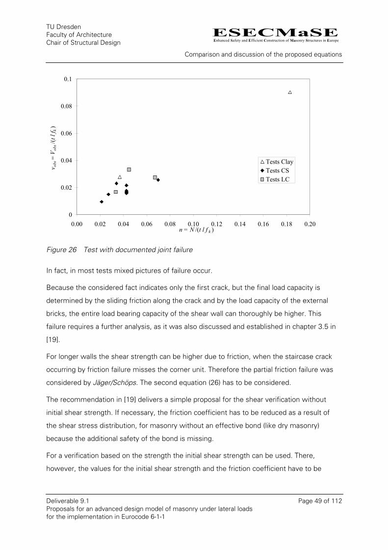
ESECMaSEEnhanced Safety and Efficient Construction of Masonry Structures in Europe
TU Dresden Faculty of Architecture Chair of Structural Design
Comparison and discussion of the proposed equations
Deliverable 9.1 Page 49 of 112 Proposals for an advanced design model of masonry under lateral loads for the implementation in Eurocode 6-1-1
0
0.02
0.04
0.06
0.08
0.1
0.00 0.02 0.04 0.06 0.08 0.10 0.12 0.14 0.16 0.18 0.20n = N /(t l f k )
v obs
= V o
bs/(t
l f k
)
Tests ClayTests CSTests LC
Figure 26 Test with documented joint failure
In fact, in most tests mixed pictures of failure occur.
Because the considered fact indicates only the first crack, but the final load capacity is
determined by the sliding friction along the crack and by the load capacity of the external
bricks, the entire load bearing capacity of the shear wall can thoroughly be higher. This
failure requires a further analysis, as it was also discussed and established in chapter 3.5 in
[19].
For longer walls the shear strength can be higher due to friction, when the staircase crack
occurring by friction failure misses the corner unit. Therefore the partial friction failure was
considered by Jäger/Schöps. The second equation (26) has to be considered.
The recommendation in [19] delivers a simple proposal for the shear verification without
initial shear strength. If necessary, the friction coefficient has to be reduced as a result of
the shear stress distribution, for masonry without an effective bond (like dry masonry)
because the additional safety of the bond is missing.
For a verification based on the strength the initial shear strength can be used. There,
however, the values for the initial shear strength and the friction coefficient have to be

ESECMaSEEnhanced Safety and Efficient Construction of Masonry Structures in Europe
TU Dresden Faculty of Architecture Chair of Structural Design
Comparison and discussion of the proposed equations
Deliverable 9.1 Page 50 of 112 Proposals for an advanced design model of masonry under lateral loads for the implementation in Eurocode 6-1-1
reduced in order to consider the failure of version 2. The reduction ratio can be calculated in
the following way:
ol
b
lh
F⋅+
=µ1
1
(66)
0
0.1
0.2
0.3
0.4
0.5
0.6
0.7
0.8
0.9
0.5 1.0 1.5 2.0 2.5 3.0 3.5 4.h b /l ol
F
0
µ=0.4µ=0.6µ=0.8
Figure 27 Reduction factor depending on the relation of unit height to overlapping length
The equation of the EC 6 for masonry with unfilled head joints results for the case of µ=0.8
and hb/lol =1.25 (cp. eq. (13)). The simplification according to DIN 1053-100 is based on
µ=0.65 and hb/lol =1.0. Masonry made of large-sized units and with staircase bond requires
an additional reduction. However, it is waived, because the influence of the corner unit is
unexplained and the final load capacity can be higher, as explained above. Moreover, the
ratio hb/lol should be restrained.
4.4. Tensile failure of the unit
While the previously discussed failure modes bending, gaping and friction – mainly
analytical failure models for the description of the shear failure – are forming the base of the
standards, an empirical model and an analytical model (DIN 1053) follows for the failure due
to principal tensile stresses in the masonry units. According to DIN 1053-1 the first principal
stress are used as criterions (eq. (21)) while the EC 6 considers the failure of tensile strength
of the unit only with a fixed boundary value, which depends on the compressive strength of
the unit (see chapter 2.2). Besides to the dependence on the tensile strength of the unit the
ESECMaSEEnhanced Safety and Efficient Construction of Masonry Structures in Europe
TU Dresden Faculty of Architecture Chair of Structural Design
Comparison and discussion of the proposed equations
Deliverable 9.1 Page 51 of 112 Proposals for an advanced design model of masonry under lateral loads for the implementation in Eurocode 6-1-1
shear strength is also a function of the vertical load. For the definition of the tensile strength
of the unit, the pattern of the holes has to be considered in addition to the compressive
strength.
The proceeding of Graubner/Kranzler in [19] and [20] are equal to a combination of an
analytical model and an empiric adjustment. The proposed equations (see eq. (31) till (33))
are based on an analytical model (Jäger/Schöps [22]) in which the parameters first were
adjusted to numerical results and afterwards to test results. As an advantage of the
numerical proceeding, different influencing factors can be investigated under controlled
boundary conditions.
The equations of this method are more complex compared to the approach of the EC 6. A
simplification is urgently necessary for a normative suggestion. Hereinafter some possible
influencing factors should be considered.
4.4.1. Influence of the vertical load
During most experimental shear tests only two ore three load steps are investigated. The
failure cases of it are mostly different. It may be that the one is bending and the other one a
tensile failure of the unit. Against it, any number of load steps can be investigated with
numerical considerations. The numerical results from [19] show the nonlinear increase of the
shear capacity with increase of the vertical load and failure of tensile strength of the units.
Concerning this matter, the criterion of the principal tensile stress is therefore applicable for
the failure in the stone, as based on the analytical derivations of Mann/Müller in [22] and
[27].
The following chart shows the tests arranges in [20] depending on the vertical stress level
with tensile failure of the units and full restraint support at the top.

ESECMaSEEnhanced Safety and Efficient Construction of Masonry Structures in Europe
TU Dresden Faculty of Architecture Chair of Structural Design
Comparison and discussion of the proposed equations
Deliverable 9.1 Page 52 of 112 Proposals for an advanced design model of masonry under lateral loads for the implementation in Eurocode 6-1-1
0
0.02
0.04
0.06
0.08
0.1
0.12
0.00 0.05 0.10 0.15 0.20 0.25 0.30 0.35 0.40 0.45n = N /(t l f k )
v obs
= V o
bs/(t
l f k
)
Tests AAC
Figure 28 Relative shear load capacity depending on the vertical stress level for AAC units
and tensile failure of the units (full restraint support at the top)
Analogue to the numerical investigation there is also a dependence on the vertical load.
There is a non-linear coherence for the example of AAC.
4.4.2. Influence of tensile strength of the unit
The numerical comparative analysis in [19] shows for a tensile strength of the unit of
1.12 N/mm² an acceptable coincidence with the existing theoretical models. For the
calculations with the reduced tensile strength of the unit, 0.2 N/mm ² instead of 1.12
N/mm², partially significantly higher capacities were revealed, than the theoretical models of
Mann/Mueller [27] and Jäger/Schöps [22] have shown (see pictures 3-29 to 3-32 and 3-37 to
3-40 in [19]).
Therefore it could be noted, that at the level of input parameters for numerical calculation
only the tensile strength of the unit changed. The other parameters, like modulus of
elasticity, compressive strength and the defined crack energy, are equal in both calculations.
Therefore the masonry with the lower tensile strength of the unit shows a significantly
ductile behaviour. Not until the quintuple crack width is reached does the tensile strength at
the crack growth become zero. With more ductile behaviour, similar to the theoretical plastic

ESECMaSEEnhanced Safety and Efficient Construction of Masonry Structures in Europe
TU Dresden Faculty of Architecture Chair of Structural Design
Comparison and discussion of the proposed equations
Deliverable 9.1 Page 53 of 112 Proposals for an advanced design model of masonry under lateral loads for the implementation in Eurocode 6-1-1
hinge, larger forces can be transferred. This is known from the investigations on the bending
tensile strength. This fact has maybe also an influence on the failure of tensile strength of
the units. Therefore comparative analyses with reduced cracking energy have to be carried
out.
In [19], only two values were available for the adjustment of the equations for the unit failure
with the tensile strength of the unit (fbt = 0.2 N/mm² and 1.12 N/mm²). Because of the
higher shear capacity at a smaller tensile strength of the unit an increase of the equation in
the lower range of fbt was carried out. Compared with the experimental results in [20] for
masonry with a small tensile strength of the unit (AAC) a reduction was implemented again.
The following chart shows the test results depending on the standardised tensile strength of
the unit.
0
0.02
0.04
0.06
0.08
0.1
0.12
0.00 0.02 0.04 0.06 0.08 0.10 0.12 0.14 0.16 0.18 0.20f bt / β D,St
v obs
= V
obs/
(t l f
k)
Tests ClayTests CSTests AACTests LC
0
0.02
0.04
0.06
0.08
0.1
0.12
0.00 0.20 0.40 0.60 0.80 1.00 1.20 1.40 1.60f bt
v obs
= V
obs/(t
l f k
)
Tests ClayTests CSTests AACTests LC
Figure 29 Relative shear load capacity depending on the tensile strength of the masonry
units (left: relative to the compressive strength of the unit)
In the following chart the ratio of the standardised tensile strength of the unit to the
standardised vertical load is shown, because the influence of the tensile strength of the unit
is superimposed with the influence of the vertical loads.
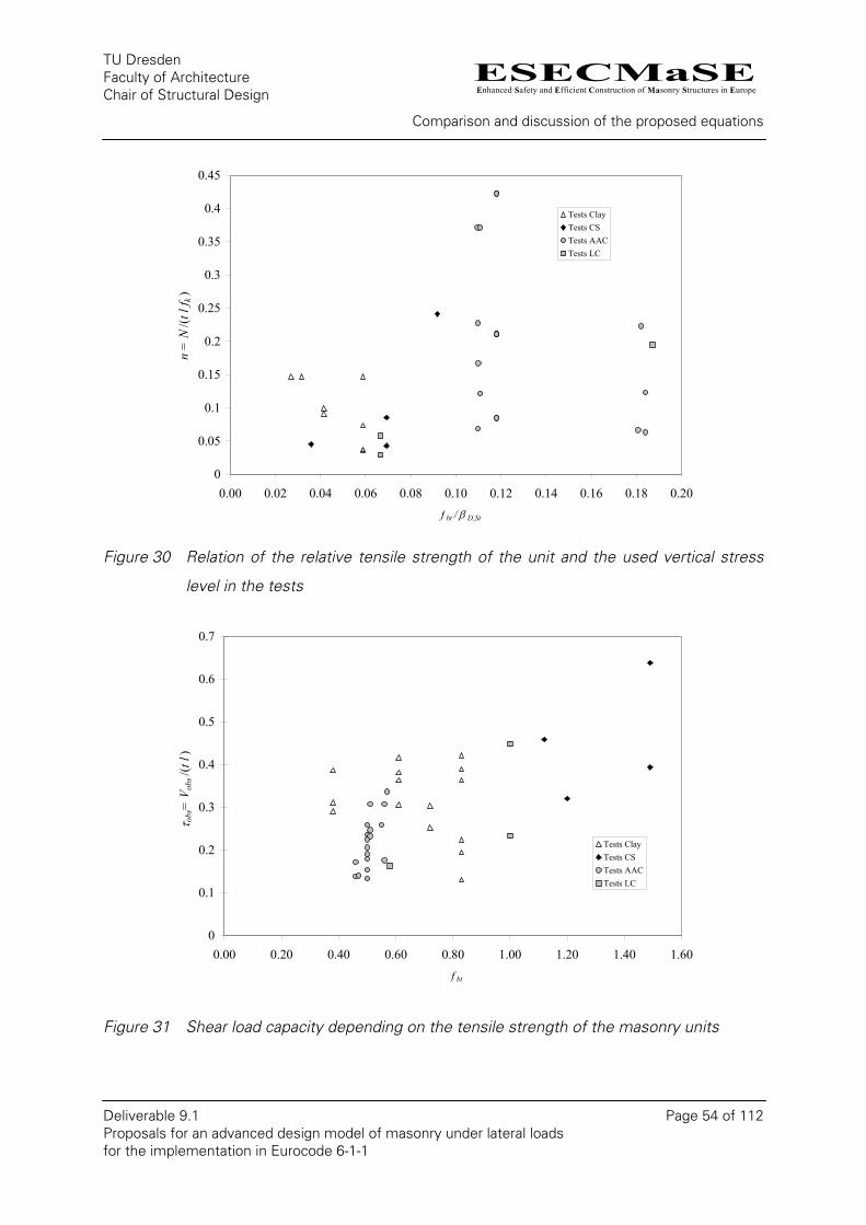
ESECMaSEEnhanced Safety and Efficient Construction of Masonry Structures in Europe
TU Dresden Faculty of Architecture Chair of Structural Design
Comparison and discussion of the proposed equations
Deliverable 9.1 Page 54 of 112 Proposals for an advanced design model of masonry under lateral loads for the implementation in Eurocode 6-1-1
0
0.05
0.1
0.15
0.2
0.25
0.3
0.35
0.4
0.45
0.00 0.02 0.04 0.06 0.08 0.10 0.12 0.14 0.16 0.18 0.20f bt / β D,St
n =
N/(t
l f k
)
Tests ClayTests CSTests AACTests LC
Figure 30 Relation of the relative tensile strength of the unit and the used vertical stress
level in the tests
0
0.1
0.2
0.3
0.4
0.5
0.6
0.7
0.00 0.20 0.40 0.60 0.80 1.00 1.20 1.40 1.60f bt
τ obs
= V
obs/(t
l)
Tests ClayTests CSTests AACTests LC
Figure 31 Shear load capacity depending on the tensile strength of the masonry units

ESECMaSEEnhanced Safety and Efficient Construction of Masonry Structures in Europe
TU Dresden Faculty of Architecture Chair of Structural Design
Comparison and discussion of the proposed equations
Deliverable 9.1 Page 55 of 112 Proposals for an advanced design model of masonry under lateral loads for the implementation in Eurocode 6-1-1
In Figure 31 a basic dependence of the shear capacity from the tensile strength of the unit
can be recognized. A more precise relationship to the unit- or masonry compressive strength
(see Figure 29) can not be established with the present experimental results. Therefore
further investigations are necessary.
4.4.3. Influence of filled head joints
For the failure due to exceeding of the tensile strength of the unit within the numerical
comparative analysis a significant increasing of the load-bearing capacity can be recognized
for masonry with filled head joints (cp. [19]). The difference between filled and unfilled joints
exists only in the contact. This means that the face sides of the bricks do not contact each
other in case of unfilled head joints. The initial shear strength was not defined in case of
filled head joints.
Within the ESECMaSE-project mainly masonry with unfilled head joints was investigated.
The influence of a contact of the face sides of the units on the shear capacity can not be
fixed by experimental data. For one test with filled head joints and AAC in [16] a significant
increasing of the load-bearing behaviour could be recognized (ca. 20%).
While within DIN 1053 filled head joints are not considered for the tension failure of the unit,
the boundary value for filled head joints in EC 6 can be raised up to 44% (0.065fb/0.0.45fb).
The number of tests is not sufficient for a separate evaluation. Already ongoing research
projects will deliver more technical expertise in the next time.
4.4.4. Influence of overlapping length / geometry of the units
According to the results in [19], the size of the unit or the overlapping length have only a
marginal influence on the shear capacity due to tension failure of the unit. Two test with a
reduced overlapping length made by Fehling/Stürz [15] showed contrary to expectations an
increasing of the load up to 25%. For these experiments the regular bond was used. The
transferability to the staircase bond still has to be investigated if necessary.
Based on the results of ESECMaSE, currently the consideration of the geometry of the
stone or the overlapping length is not necessary for the shear verification due to tension
failure of the unit.
ESECMaSEEnhanced Safety and Efficient Construction of Masonry Structures in Europe
TU Dresden Faculty of Architecture Chair of Structural Design
Comparison and discussion of the proposed equations
Deliverable 9.1 Page 56 of 112 Proposals for an advanced design model of masonry under lateral loads for the implementation in Eurocode 6-1-1
4.4.5. Influence of the ratio between unit and wall
In the investigations in [22] of about the influence of the ratio between unit and wall
geometry greater capacities for large stones were measured.
The results of the numerical simulation of the walls D_1 and D_11 in [19] gave slightly
smaller capacities on the other hand, when using large stones (see Figure 3-25 and 3-28).
For large sized units it seems that the aspect ratio of the unit have now an impact on the
results (see D_8 and D_11). Within ESECMaSE in Pavia also tests with KS Quadro-elements
were made. The pictures show a joint failure in combination with a bending failure.
A clear statement could not yet be given. Therefore a consideration for the standard will be
omitted in this report.
4.4.6. Influence of a full restrained support at the top of the wall
The determination of the shear load capacity as a result of unit failure by half a wall height
after eq. (37) and (38) leads to the same shear loads capacities for a full restrained top of the
wall and for the static system of a cantilever. Only a few comparative tests results are
available for that.
Thus different kinds of failure were decisive at the experiments 7 and 8 from Pavia (cp.
Figure 3-11 in [20]). The same applies to the tests 1, 2 and 6 from Pavia (cp. Figure 3-12 in
[20]). With the tests 19 and 22 of the University of Kassel tensile failure of the units or
bending failure appeared with the same geometry and load. The load of the wall with full
restraint support was twice as big, on this occasion (cp. Figure 3-8 right and Figure 3-9 in
[20]). The test values lie both just under the curve for the bending failure.
As a clue for the influence can be used the numerical investigations in [19] on the wall D_3.
In Figure 2-14 both static systems are confronted with each other. The difference amounts
to 20%-25%.
For the consideration of this influence the calculated wall length can be used (see
chapter 6.2). The factor c for the shear stress distribution defined by the shear slenderness
is not suited (see chapter 5).
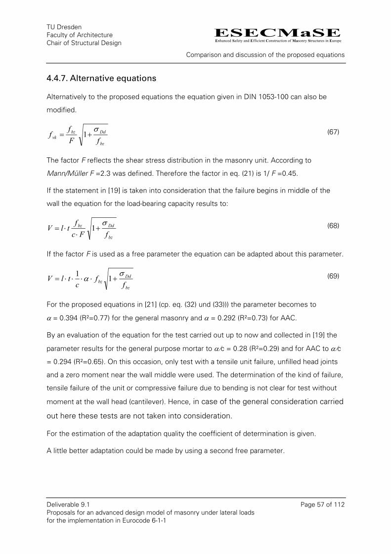
ESECMaSEEnhanced Safety and Efficient Construction of Masonry Structures in Europe
TU Dresden Faculty of Architecture Chair of Structural Design
Comparison and discussion of the proposed equations
Deliverable 9.1 Page 57 of 112 Proposals for an advanced design model of masonry under lateral loads for the implementation in Eurocode 6-1-1
4.4.7. Alternative equations
Alternatively to the proposed equations the equation given in DIN 1053-100 can also be
modified.
bz
Ddbzvk fF
ff
σ+= 1 (67)
The factor F reflects the shear stress distribution in the masonry unit. According to
Mann/Müller F =2.3 was defined. Therefore the factor in eq. (21) is 1/ F =0.45.
If the statement in [19] is taken into consideration that the failure begins in middle of the
wall the equation for the load-bearing capacity results to:
bz
Ddbz
fFcf
tlVσ
+⋅
⋅= 1 (68)
If the factor F is used as a free parameter the equation can be adapted about this parameter.
bz
Ddbz f
fc
tlVσ
α +⋅⋅⋅⋅= 11 (69)
For the proposed equations in [21] (cp. eq. (32) und (33))) the parameter becomes to
α = 0.394 (R²=0.77) for the general masonry and α = 0.292 (R²=0.73) for AAC.
By an evaluation of the equation for the test carried out up to now and collected in [19] the
parameter results for the general purpose mortar to α/c = 0.28 (R²=0.29) and for AAC to α/c
= 0.294 (R²=0.65). On this occasion, only test with a tensile unit failure, unfilled head joints
and a zero moment near the wall middle were used. The determination of the kind of failure,
tensile failure of the unit or compressive failure due to bending is not clear for test without
moment at the wall head (cantilever). Hence, in case of the general consideration carried
out here these tests are not taken into consideration.
For the estimation of the adaptation quality the coefficient of determination is given.
A little better adaptation could be made by using a second free parameter.
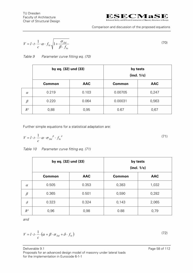
ESECMaSEEnhanced Safety and Efficient Construction of Masonry Structures in Europe
TU Dresden Faculty of Architecture Chair of Structural Design
Comparison and discussion of the proposed equations
Deliverable 9.1 Page 58 of 112 Proposals for an advanced design model of masonry under lateral loads for the implementation in Eurocode 6-1-1
bz
Ddbz f
fc
tlV⋅
+⋅⋅⋅⋅=β
α 11 (70)
Table 9 Parameter curve fitting eq. (70)
by eq. (32) und (33) by tests
(incl. 1/c)
σ
Common AAC Common AAC
α 0.219 0.103 0 .00705 0,247
β 0.220 0.064 0.00031 0,563
R² 0,88 0,95 0.67 0,67
Further simple equations for a statistical adaptation are:
δβσα btDd fc
tlV ⋅⋅⋅⋅⋅=1
(71)
Table 10 Parameter curve fitting eq. (71)
by eq. (32) und (33) by tests
(incl. 1/c)
Common AAC C ommon AAC
α 0.505 0.353 0,383 1,032
β 0.365 0.501 0,590 0,282
δ 0.323 0.324 0,143 2,065
R² 0,96 0,98 0.88 0,79
and
( )btDd fc
tlV ⋅+⋅+⋅⋅⋅= δσβα1 (72)

ESECMaSEEnhanced Safety and Efficient Construction of Masonry Structures in Europe
TU Dresden Faculty of Architecture Chair of Structural Design
Comparison and discussion of the proposed equations
Deliverable 9.1 Page 59 of 112 Proposals for an advanced design model of masonry under lateral loads for the implementation in Eurocode 6-1-1
Table 11 Param 2)
by eq. (32) und (33) by tests
eter curve fitting eq. (7
(incl. 1/c)
Common AAC C ommon AAC
α 0.069 0.011 0,084 -0,285
β 0.148 0.142 0,236 0,101
δ 0.270 0.233 0,051 0,866
R² 0,98 0,99 0.85 0,73
Table 12 Param 2) without α
by eq. (32) und (33) by tests
eter curve fitting eq. (7
(incl. 1/c)
Common AAC Common AAC
α - - - -
β 0.164 0.144 0.270 0.115
δ 0.327 0.253 0.107 0.212
R² 0.96 0.99 0.80 0.65
The best result by the adaptation to the test results arose for an equation with free
exponents (eq. (71)). This equation is the same function as for the calculation of the masonry
compressive strength. Indeed, the coefficient of determination of the AAC masonry is
clearly lower as for the general masonry. This could also be seen at the parameter δ , which
corresponds to a nearly quadratic dependence of the shear load capacity on the tensile
strength of the unit. An adaptation of the equations for AAC masonry to the tensile strength
of the unit is not possible with the available data, as could already be seen in the diagram in
Figure 29 right.
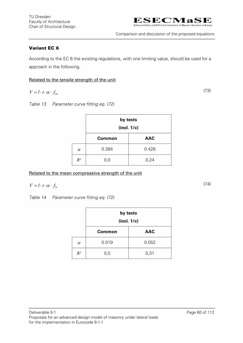
ESECMaSEEnhanced Safety and Efficient Construction of Masonry Structures in Europe
TU Dresden Faculty of Architecture Chair of Structural Design
Comparison and discussion of the proposed equations
Deliverable 9.1 Page 60 of 112 Proposals for an advanced design model of masonry under lateral loads for the implementation in Eurocode 6-1-1
Variant EC 6
According to the EC 6 the existing regulations, with one limiting value, should be used
approach in the following.
Related to the tensile strength of the unit
for a
btftlV ⋅⋅⋅= α (73)
Table 13 Parameter curve fitting
by tests
(incl. 1/c)
eq. (72)
Common AAC
α 0.384 0.428
R² 0,0 0,24
Related to the mean compressive strength of the unit
bftlV ⋅⋅⋅= α (74)
Table 14 Parameter curve fitting
by tests
(incl. 1/c)
eq. (72)
Common AAC
α 0.019 0.052
R² 0,0 0,31
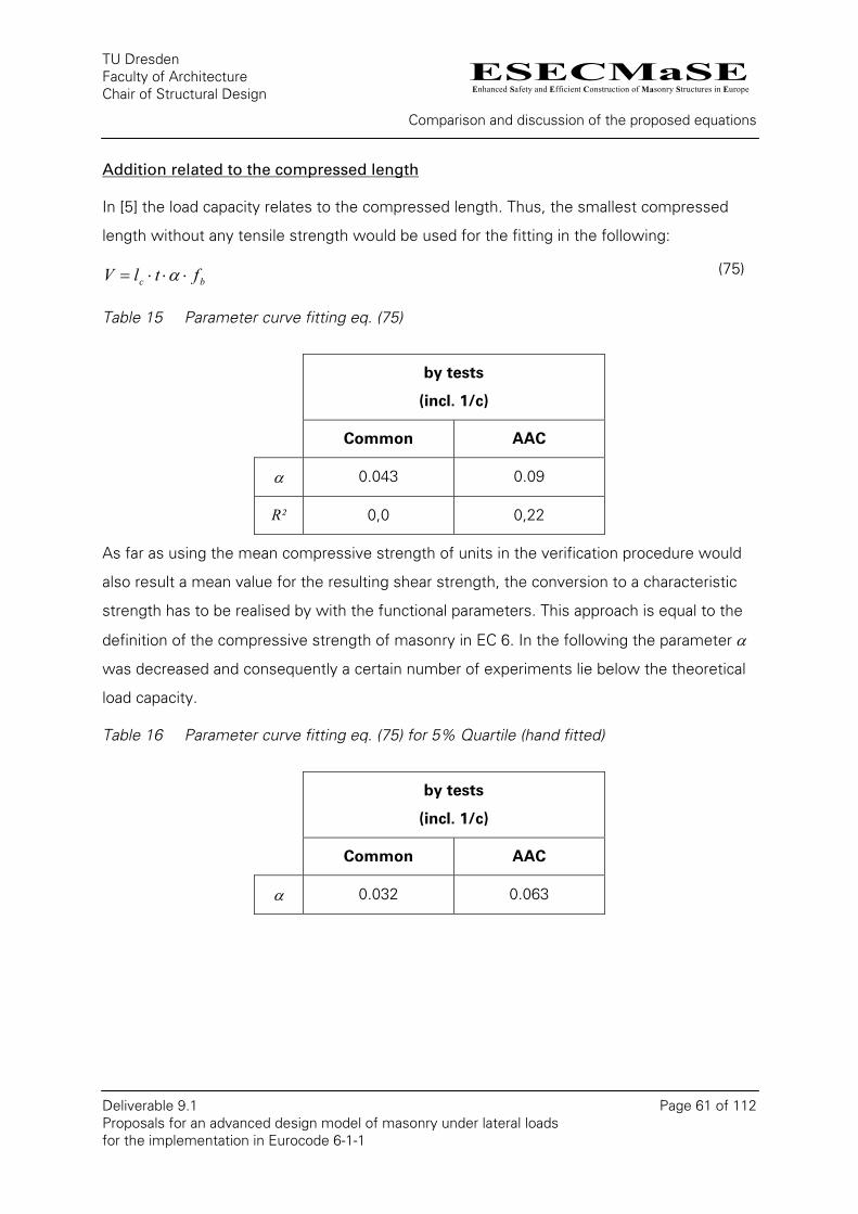
ESECMaSEEnhanced Safety and Efficient Construction of Masonry Structures in Europe
TU Dresden Faculty of Architecture Chair of Structural Design
Comparison and discussion of the proposed equations
Deliverable 9.1 Page 61 of 112 Proposals for an advanced design model of masonry under lateral loads for the implementation in Eurocode 6-1-1
Addition related to the compressed length
In [5] the load capacity relates to the compressed length. Thus, the smallest compressed
length without any tensile strength would be used for the fitting in the following:
bc ftlV ⋅⋅⋅= α (75)
Table 15 Parameter curve fitting eq. (75)
by tests
(incl. 1/c)
Common AAC
α 0.043 0.09
R² 0,0 0,22
As far as using the mean compressive strength of units in the verification procedure would
also result a mean value for the resulting shear strength, the conversion to a characteristic
strength has to be realised by with the functional parameters. This approach is equal to the
definition of the compressive strength of masonry in EC 6. In the following the parameter α
was decreased and consequently a certain number of experiments lie below the theoretical
load capacity.
Table 16 Parameter curve fitting eq. (75) for 5% Quartile (hand fitted)
by tests
(incl. 1/c)
Common AAC
α 0.032 0.063
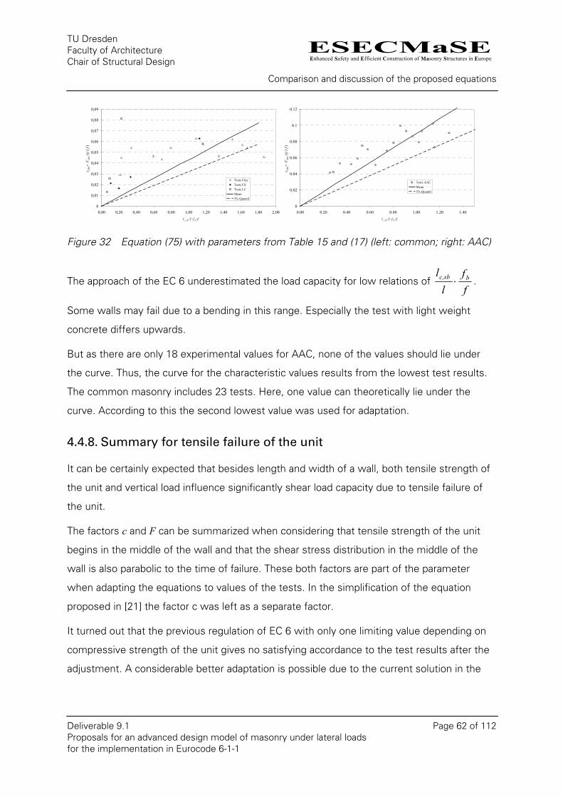
ESECMaSEEnhanced Safety and Efficient Construction of Masonry Structures in Europe
TU Dresden Faculty of Architecture Chair of Structural Design
Comparison and discussion of the proposed equations
Deliverable 9.1 Page 62 of 112 Proposals for an advanced design model of masonry under lateral loads for the implementation in Eurocode 6-1-1
0
0,01
0,02
0,03
0,04
0,05
0,06
0,07
0,08
0,09
0,00 0,20 0,40 0,60 0,80 1,00 1,20 1,40 1,60 1,80 2,00l c,sb /l ·f b /f
v obs
= V
obs/
(t l f
)
Tests ClayTests CSTests LCMean5% Quantil
0
0.02
0.04
0.06
0.08
0.1
0.12
0.00 0.20 0.40 0.60 0.80 1.00 1.20 1.40l c,sb /l ·f b /f
v obs
= V
obs/
(t l f
)
Tests AACMean5% Quantil
Figure 32 Equation (75) with parameters from Table 15 and (17) (left: common; right: AAC)
The approach of the EC 6 underestimated the load capacity for low relations of ff
ll bc,sb ⋅ .
Some walls may fail due to a bending in this range. Especially the test with light weight
concrete differs upwards.
But as there are only 18 experimental values for AAC, none of the values should lie under
the curve. Thus, the curve for the characteristic values results from the lowest test results.
The common masonry includes 23 tests. Here, one value can theoretically lie under the
curve. According to this the second lowest value was used for adaptation.
4.4.8. Summary for tensile failure of the unit
It can be certainly expected that besides length and width of a wall, both tensile strength of
the unit and vertical load influence significantly shear load capacity due to tensile failure of
the unit.
The factors c and F can be summarized when considering that tensile strength of the unit
begins in the middle of the wall and that the shear stress distribution in the middle of the
wall is also parabolic to the time of failure. These both factors are part of the parameter
when adapting the equations to values of the tests. In the simplification of the equation
proposed in [21] the factor c was left as a separate factor.
It turned out that the previous regulation of EC 6 with only one limiting value depending on
compressive strength of the unit gives no satisfying accordance to the test results after the
adjustment. A considerable better adaptation is possible due to the current solution in the

ESECMaSEEnhanced Safety and Efficient Construction of Masonry Structures in Europe
TU Dresden Faculty of Architecture Chair of Structural Design
Comparison and discussion of the proposed equations
Deliverable 9.1 Page 63 of 112 Proposals for an advanced design model of masonry under lateral loads for the implementation in Eurocode 6-1-1
German standard. When using two free parameters a coefficient of determination of 0.67
compared to the values of the experiments and of 0.91 to the equations in [21] will result.
Still higher coefficient of determination can be reached with the exponential and the linear
approach. For both 3 free parameters for adapting were used. But the linear approach gives
for a theoretical tensile strength of the unit of zero and without load a low but not irrelevant
shear load capacity. The solution with the exponential approach results for a load close to
zero a shear load capacity also close to zero independent of the tensile strength of the unit.
But it can be seen when adapting the values of the experiments that in face of the high
coefficient of determination wrong values could be result. A considerable disadvantage of
the statistic approach is due to the still minor database. Compared to the definition of
compressive strength of masonry the size is less than 1/10 at a greater number of possible
influencing factors. There are still analytical/numerical considerations necessary to define
accurate equations. That is why the proposal for the standard is based on a simplification of
the equation in [21]. For this, equation (70) is applied based on DIN 1053-100.
ESECMaSEEnhanced Safety and Efficient Construction of Masonry Structures in Europe
TU Dresden Faculty of Architecture Chair of Structural Design
Shear Stress Distribution
Deliverable 9.1 Page 64 of 112 Proposals for an advanced design model of masonry under lateral loads for the implementation in Eurocode 6-1-1
5. Shear Stress Distribution
In [24] the shear stress distribution was investigated. The classic bending theory gives a
shear factor c = 1.5 for the maximum shear stress for a rectangular cross section. The
maximum shear stress is calculated by:
AVc ⋅=τmax (76)
V shear force
A area of the cross section
In some codes the shear factor is explicitly prescribed. In the German masonry code
DIN 1053 the factor depends on the wall geometry. In the Eurocode 6 (EN1996-1-1 [5]) the
factor is neglected or should be implicit included in the equations for the shear strength.
In [24] the classic bending theory was combined with a nonlinear material behaviour to
calculate the shear stress distribution in case of plasticity. The maximum shear stress
reaches a value of 1,78 · V/A for a example beam. The maximum shear stress further
increases for a material law with a softening if the maximum strain is reached. The reason
for this is the smaller area of the cross section which can take even further load increases.
The example shows that the plastic deformation due to bending does not lead to a reduction
of the maximum shear stress.
Another way to obtain information about the shear stress distribution is to measure the
strain at a wall during shear test. For this, two walls with different vertical loads were tested
(see also [24]). For the first one the load was chosen to get a tension failure in the units. The
second one should have the failures in the joints. Strain gauges were placed on the walls in
several places.
In the first load step the vertical load was imposed on the wall. Logically in this step no
shear stress were established in the middle of the wall. At the bottom the R/C beam
restricted by his higher stiffness the horizontal expansion of the masonry, which leads to an
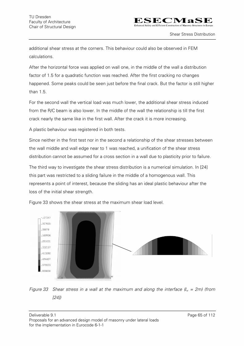
ESECMaSEEnhanced Safety and Efficient Construction of Masonry Structures in Europe
TU Dresden Faculty of Architecture Chair of Structural Design
Shear Stress Distribution
Deliverable 9.1 Page 65 of 112 Proposals for an advanced design model of masonry under lateral loads for the implementation in Eurocode 6-1-1
additional shear stress at the corners. This behaviour could also be observed in FEM
calculations.
After the horizontal force was applied on wall one, in the middle of the wall a distribution
factor of 1.5 for a quadratic function was reached. After the first cracking no changes
happened. Some peaks could be seen just before the final crack. But the factor is still higher
than 1.5.
For the second wall the vertical load was much lower, the additional shear stress induced
from the R/C beam is also lower. In the middle of the wall the relationship is till the first
crack nearly the same like in the first wall. After the crack it is more increasing.
A plastic behaviour was registered in both tests.
Since neither in the first test nor in the second a relationship of the shear stresses between
the wall middle and wall edge near to 1 was reached, a unification of the shear stress
distribution cannot be assumed for a cross section in a wall due to plasticity prior to failure.
The third way to investigate the shear stress distribution is a numerical simulation. In [24]
this part was restricted to a sliding failure in the middle of a homogenous wall. This
represents a point of interest, because the sliding has an ideal plastic behaviour after the
loss of the initial shear strength.
Figure 33 shows the shear stress at the maximum shear load level.
Figure 33 Shear stress in a wall at the maximum and along the interface (lw = 2m) (from
[24])

ESECMaSEEnhanced Safety and Efficient Construction of Masonry Structures in Europe
TU Dresden Faculty of Architecture Chair of Structural Design
Shear Stress Distribution
Deliverable 9.1 Page 66 of 112 Proposals for an advanced design model of masonry under lateral loads for the implementation in Eurocode 6-1-1
At the maximum shear load a nonlinear shear stress distribution could be seen. If the
horizontal load or displacement at the top of the wall increases more, sudden changes
happen. The connections at the interface snap off. The next figure shows the shear stress
and the deformation of the wall after the wall starts to slide. On the right the average shear
stress is plotted against the horizontal displacement at the top of the wall. Due to sliding a
constant shear stress state in the interface region is established. The resistance force
remains also constant for further horizontal displacement.
0.00
0.10
0.20
0.30
0.40
0.50
0.0 1.0 2.0 3.0 4.0 5.0 6.0
horizontal Displacem ent at the top (m m )
aver
age
shea
r stre
ss (N
/mm
²)c· (f vk0 + µ · σ )
1.0· (µ · σ )
Figure 34 Shear stress in a wall after sliding and load-displacement-curve (lw = 2m) (from
[24])
The average shear strength for the investigated area is given by:
⎪⎩
⎪⎨⎧
⋅
⋅+=
σµ
σµc
ff
vk
v
0
max (77)

ESECMaSEEnhanced Safety and Efficient Construction of Masonry Structures in Europe
TU Dresden Faculty of Architecture Chair of Structural Design
Shear Stress Distribution
Deliverable 9.1 Page 67 of 112 Proposals for an advanced design model of masonry under lateral loads for the implementation in Eurocode 6-1-1
In the following diagrams some dependencies for the factor c could be seen.
1
1.1
1.2
1.3
1.4
1.5
0 2 4 6 8 10
Length of the wall (m )
Shea
r fac
tor c
1
1.1
1.2
1.3
1.4
1.5
0.4 0.6 0.8 1
perpenticular s tress (N/m m ²)S
hear
fact
or c
.0
fvk0 = 0.05 N/m m ²
fvk0 = 0.3 N/m m ²
Figure 35 Shear factor for sliding in the middle of the wall depending on the length of the
wall, the vertical stress and initial shear strength (GfII = 0.02 N/mm; left:
fvko = 0.5 N/mm²; right: lw = 2 m) (from [24])
With the done numerical parametric study a dependencies of the factor c on the crack
energy, the wall length, and the relation between the initial shear strength and the stress
perpendicular to the joint could be detected.
The principle conclusion from [24] is that the shear stress distribution can not be neglected.
A shear stress distribution factor greater than 1.0 arises from the theoretical, the
experimental and numeric analysis in any investigated cases. To be on the safe side 1.5
should be used as the factor for the shear stress distribution. In the case of high crack
energy or very large walls a smaller value could be used.
The numerical investigations of the shear stress distribution in [19] also confirmed this fact
and result a shear stress distribution factor between 1.4 and 1.5. Alternatively to the
regulation of DIN 1053-100 it is proposed in [19] to use shear slenderness to calculate the
shear stress distribution factor c.
c = 1.0 ≤0.5+λv≤1.5 (78)

ESECMaSEEnhanced Safety and Efficient Construction of Masonry Structures in Europe
TU Dresden Faculty of Architecture Chair of Structural Design
Shear Stress Distribution
Deliverable 9.1 Page 68 of 112 Proposals for an advanced design model of masonry under lateral loads for the implementation in Eurocode 6-1-1
Where:
lh
v ⋅=ψλ shear slenderness
ψ = 1.0 for cantilever systems
ψ = 0.5 for full fixed walls with full restraint at the top.
In DIN 1053-100 [3] the calculation rule is basically:
1.52
0,5 1.0 ≤+≤=l
hc (79)
0,8
0,9
1
1,1
1,2
1,3
1,4
1,5
1,6
0,00 1,00 2,00 3,00 4,00 5,00 6,00l [m]
c
cantilever
full restrained
Figure 36 Comparison of the factor for the shear stress distribution for a wall high of 2.5 m
The curve for the full restrained wall is equal to the definition of DIN 1053-100 [3]. But it is
clearly under the one in Figure 35 at the same statistic system.
In identical design equations, e. g. for tensile failure of the unit in the middle of the wall, a
load capacity difference between the walls of the same size but with a different restraint
grade is only shown with factor c. The biggest difference between the cantilever and a full
restraint results at a quadratic wall. In this case the load capacity would be 50 % higher
when appearing shear failure with full restraint like the following graph shows:
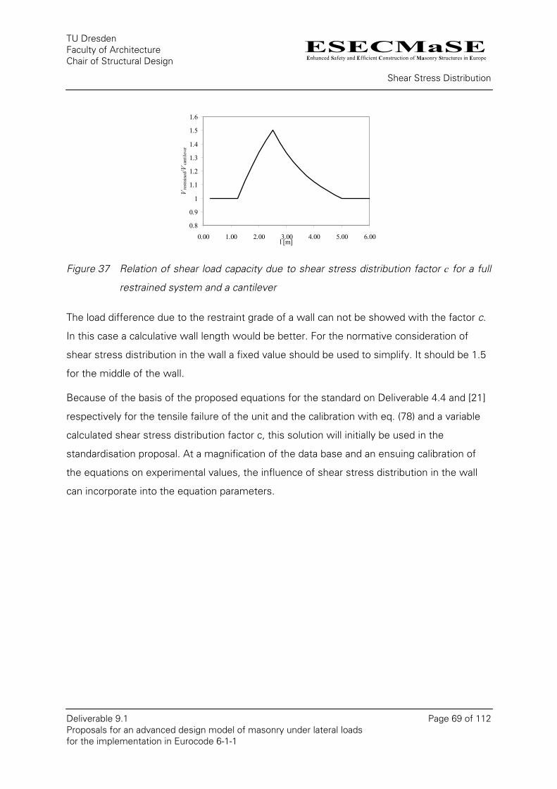
ESECMaSEEnhanced Safety and Efficient Construction of Masonry Structures in Europe
TU Dresden Faculty of Architecture Chair of Structural Design
Shear Stress Distribution
Deliverable 9.1 Page 69 of 112 Proposals for an advanced design model of masonry under lateral loads for the implementation in Eurocode 6-1-1
0.8
0.9
1
1.1
1.2
1.3
1.4
1.5
1.6
0.00 1.00 2.00 3.00 4.00 5.00 6.00l [m]
Vre
stra
ined
/Vca
ntile
ver
Figure 37 Relation of shear load capacity due to shear stress distribution factor c for a full
restrained system and a cantilever
The load difference due to the restraint grade of a wall can not be showed with the factor c.
In this case a calculative wall length would be better. For the normative consideration of
shear stress distribution in the wall a fixed value should be used to simplify. It should be 1.5
for the middle of the wall.
Because of the basis of the proposed equations for the standard on Deliverable 4.4 and [21]
respectively for the tensile failure of the unit and the calibration with eq. (78) and a variable
calculated shear stress distribution factor c, this solution will initially be used in the
standardisation proposal. At a magnification of the data base and an ensuing calibration of
the equations on experimental values, the influence of shear stress distribution in the wall
can incorporate into the equation parameters.
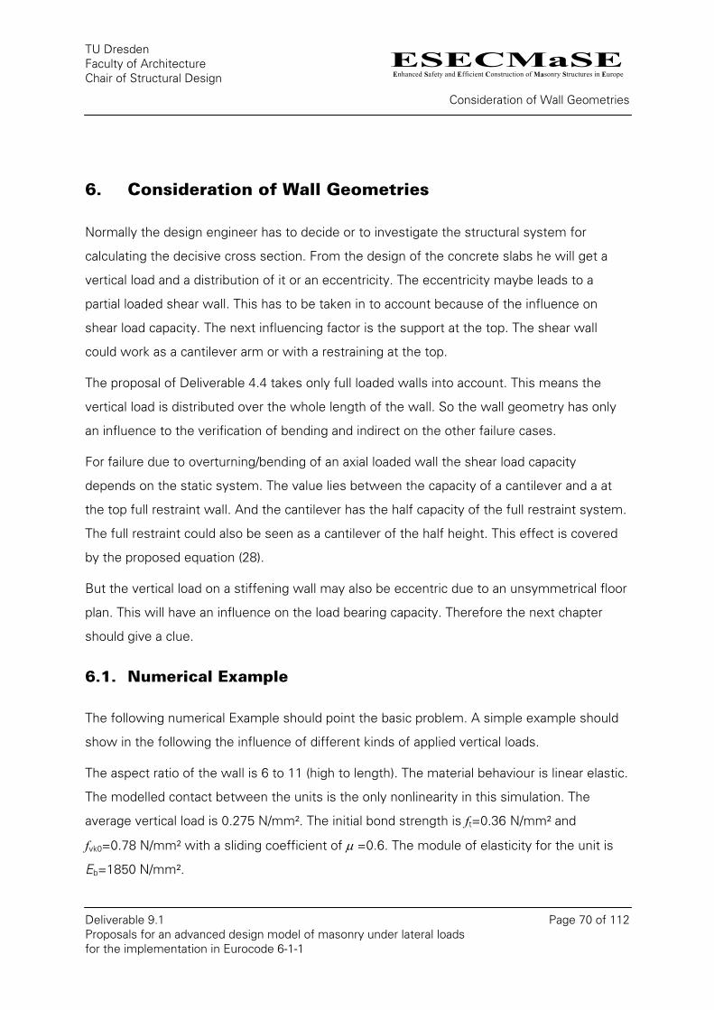
ESECMaSEEnhanced Safety and Efficient Construction of Masonry Structures in Europe
TU Dresden Faculty of Architecture Chair of Structural Design
Consideration of Wall Geometries
Deliverable 9.1 Page 70 of 112 Proposals for an advanced design model of masonry under lateral loads for the implementation in Eurocode 6-1-1
6. Consideration of Wall Geometries
Normally the design engineer has to decide or to investigate the structural system for
calculating the decisive cross section. From the design of the concrete slabs he will get a
vertical load and a distribution of it or an eccentricity. The eccentricity maybe leads to a
partial loaded shear wall. This has to be taken in to account because of the influence on
shear load capacity. The next influencing factor is the support at the top. The shear wall
could work as a cantilever arm or with a restraining at the top.
The proposal of Deliverable 4.4 takes only full loaded walls into account. This means the
vertical load is distributed over the whole length of the wall. So the wall geometry has only
an influence to the verification of bending and indirect on the other failure cases.
For failure due to overturning/bending of an axial loaded wall the shear load capacity
depends on the static system. The value lies between the capacity of a cantilever and a at
the top full restraint wall. And the cantilever has the half capacity of the full restraint system.
The full restraint could also be seen as a cantilever of the half height. This effect is covered
by the proposed equation (28).
But the vertical load on a stiffening wall may also be eccentric due to an unsymmetrical floor
plan. This will have an influence on the load bearing capacity. Therefore the next chapter
should give a clue.
6.1. Numerical Example
The following numerical Example should point the basic problem. A simple example should
show in the following the influence of different kinds of applied vertical loads.
The aspect ratio of the wall is 6 to 11 (high to length). The material behaviour is linear elastic.
The modelled contact between the units is the only nonlinearity in this simulation. The
average vertical load is 0.275 N/mm². The initial bond strength is ft=0.36 N/mm² and
fvk0=0.78 N/mm² with a sliding coefficient of µ =0.6. The module of elasticity for the unit is
Eb=1850 N/mm².
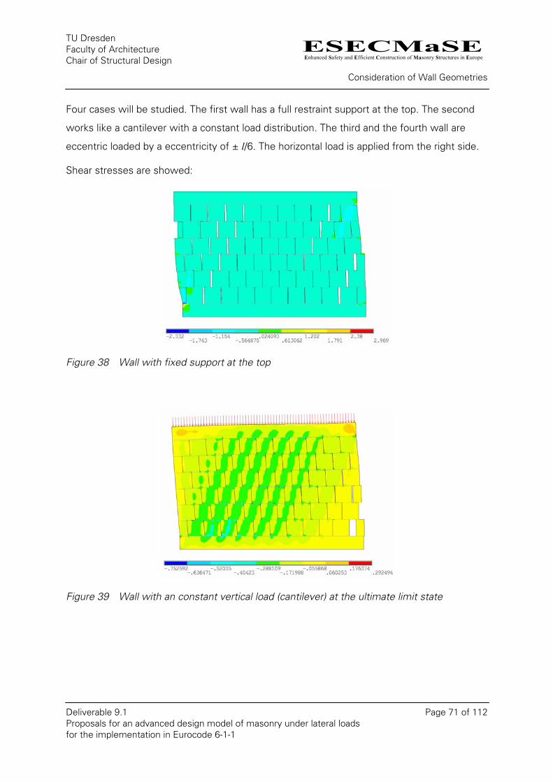
ESECMaSEEnhanced Safety and Efficient Construction of Masonry Structures in Europe
TU Dresden Faculty of Architecture Chair of Structural Design
Consideration of Wall Geometries
Deliverable 9.1 Page 71 of 112 Proposals for an advanced design model of masonry under lateral loads for the implementation in Eurocode 6-1-1
Four cases will be studied. The first wall has a full restraint support at the top. The second
works like a cantilever with a constant load distribution. The third and the fourth wall are
eccentric loaded by a eccentricity of ± l/6. The horizontal load is applied from the right side.
Shear stresses are showed:
Figure 38 Wall with fixed support at the top
Figure 39 Wall with an constant vertical load (cantilever) at the ultimate limit state
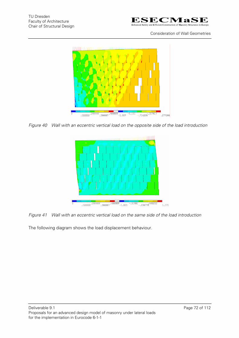
ESECMaSEEnhanced Safety and Efficient Construction of Masonry Structures in Europe
TU Dresden Faculty of Architecture Chair of Structural Design
Consideration of Wall Geometries
Deliverable 9.1 Page 72 of 112 Proposals for an advanced design model of masonry under lateral loads for the implementation in Eurocode 6-1-1
Figure 40 Wall with an eccentric vertical load on the opposite side of the load introduction
Figure 41 Wall with an eccentric vertical load on the same side of the load introduction
The following diagram shows the load displacement behaviour.
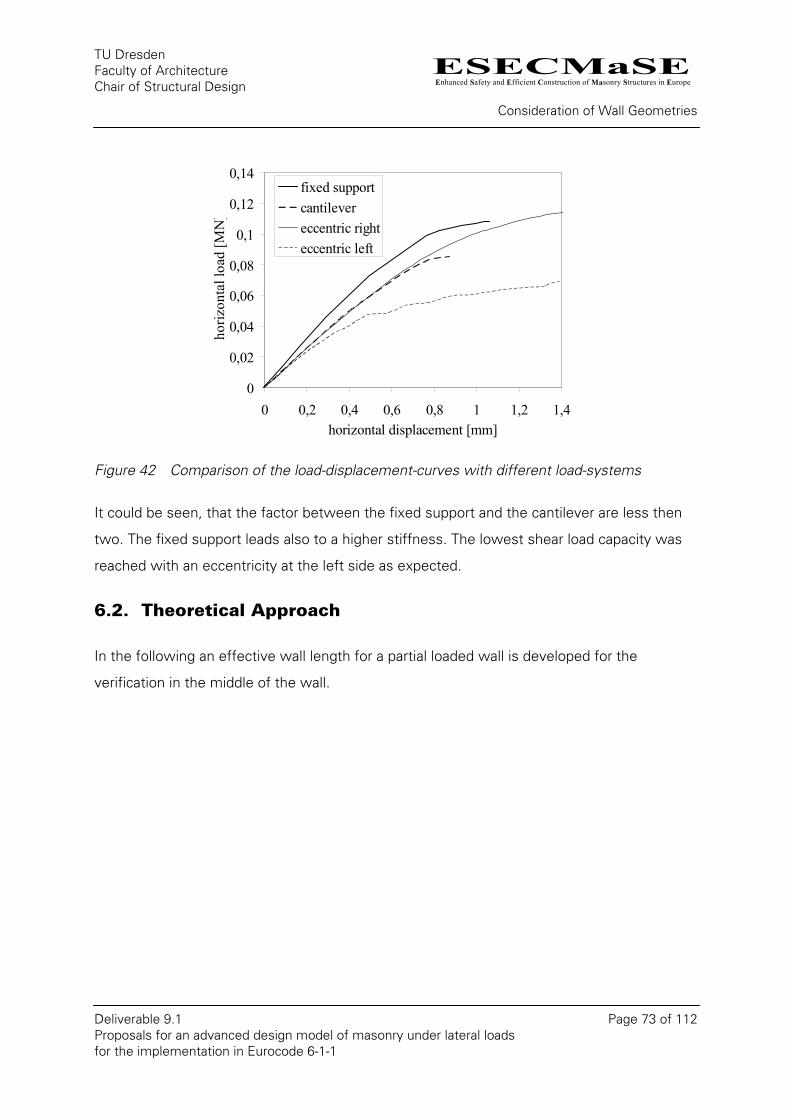
ESECMaSEEnhanced Safety and Efficient Construction of Masonry Structures in Europe
TU Dresden Faculty of Architecture Chair of Structural Design
Consideration of Wall Geometries
Deliverable 9.1 Page 73 of 112 Proposals for an advanced design model of masonry under lateral loads for the implementation in Eurocode 6-1-1
0
0,02
0,04
0,06
0,08
0,1
0,12
0,14
0 0,2 0,4 0,6 0,8 1 1,2 1,4horizontal displacement [mm]
horiz
onta
l loa
d [M
N]
fixed supportcantilevereccentric righteccentric left
Figure 42 Comparison of the load-displacement-curves with different load-systems
It could be seen, that the factor between the fixed support and the cantilever are less then
two. The fixed support leads also to a higher stiffness. The lowest shear load capacity was
reached with an eccentricity at the left side as expected.
6.2. Theoretical Approach
In the following an effective wall length for a partial loaded wall is developed for the
verification in the middle of the wall.
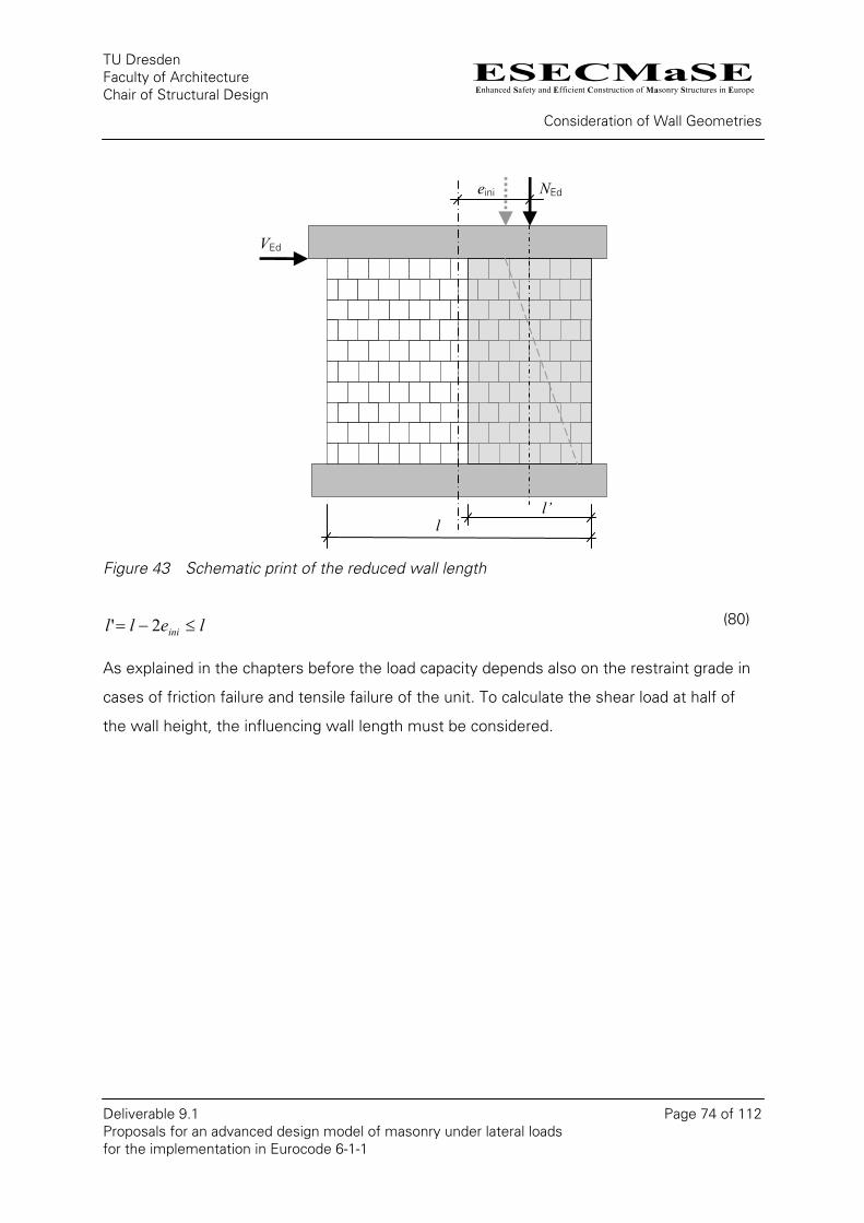
ESECMaSEEnhanced Safety and Efficient Construction of Masonry Structures in Europe
TU Dresden Faculty of Architecture Chair of Structural Design
Consideration of Wall Geometries
Deliverable 9.1 Page 74 of 112 Proposals for an advanced design model of masonry under lateral loads for the implementation in Eurocode 6-1-1
eini NEd
VEd
l’l
Figure 43 Schematic print of the reduced wall length
lell ini ≤−= 2' (80)
As explained in the chapters before the load capacity depends also on the restraint grade in
cases of friction failure and tensile failure of the unit. To calculate the shear load at half of
the wall height, the influencing wall length must be considered.
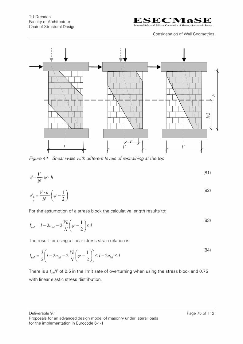
ESECMaSEEnhanced Safety and Efficient Construction of Masonry Structures in Europe
TU Dresden Faculty of Architecture Chair of Structural Design
Consideration of Wall Geometries
Deliverable 9.1 Page 75 of 112 Proposals for an advanced design model of masonry under lateral loads for the implementation in Eurocode 6-1-1
Figure 44 Shear walls with different levels of restraining at the top
hNVe ⋅⋅= ψ'
(81)
⎟⎠⎞
⎜⎝⎛ −⋅
⋅=
21'
2
ψN
hVe h (82)
For the assumption of a stress block the calculative length results to:
lNVhell inical ≤⎟
⎠⎞
⎜⎝⎛ −−−=
2122 ψ
(83)
The result for using a linear stress-strain-relation is:
lelNVhell iniinical ≤−≤⎟⎟
⎠
⎞⎜⎜⎝
⎛⎟⎠⎞
⎜⎝⎛ −−−= 2
2122
23 ψ
(84)
There is a lcal/l’ of 0.5 in the limit sate of overturning when using the stress block and 0.75
with linear elastic stress distribution.
l’ l’ l’
hh/
2
e’
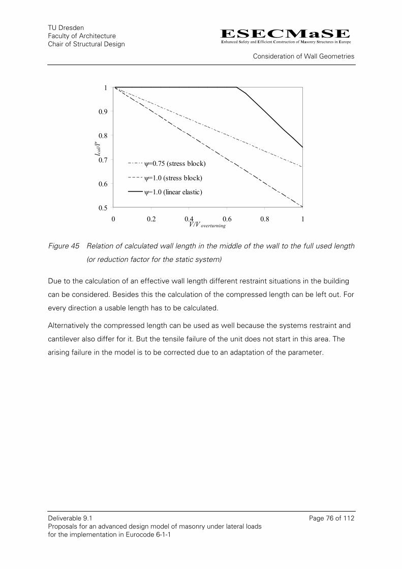
ESECMaSEEnhanced Safety and Efficient Construction of Masonry Structures in Europe
TU Dresden Faculty of Architecture Chair of Structural Design
Consideration of Wall Geometries
Deliverable 9.1 Page 76 of 112 Proposals for an advanced design model of masonry under lateral loads for the implementation in Eurocode 6-1-1
0.5
0.6
0.7
0.8
0.9
1
0 0.2 0.4 0.6 0.8 1V/V overturning
l cal/l
'
ψ=0.75 (stress block)
ψ=1.0 (stress block)
ψ=1.0 (linear elastic)
Figure 45 Relation of calculated wall length in the middle of the wall to the full used length
(or reduction factor for the static system)
Due to the calculation of an effective wall length different restraint situations in the building
can be considered. Besides this the calculation of the compressed length can be left out. For
every direction a usable length has to be calculated.
Alternatively the compressed length can be used as well because the systems restraint and
cantilever also differ for it. But the tensile failure of the unit does not start in this area. The
arising failure in the model is to be corrected due to an adaptation of the parameter.
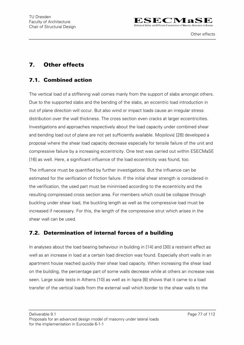
ESECMaSEEnhanced Safety and Efficient Construction of Masonry Structures in Europe
TU Dresden Faculty of Architecture Chair of Structural Design
Other effects
Deliverable 9.1 Page 77 of 112 Proposals for an advanced design model of masonry under lateral loads for the implementation in Eurocode 6-1-1
7. Other effects
7.1. Combined action
The vertical load of a stiffening wall comes manly from the support of slabs amongst others.
Due to the supported slabs and the bending of the slabs, an eccentric load introduction in
out of plane direction will occur. But also wind or impact loads cause an irregular stress
distribution over the wall thickness. The cross section even cracks at larger eccentricities.
Investigations and approaches respectively about the load capacity under combined shear
and bending load out of plane are not yet sufficiently available. Mojsilović [28] developed a
proposal where the shear load capacity decrease especially for tensile failure of the unit and
compressive failure by a increasing eccentricity. One test was carried out within ESECMaSE
[16] as well. Here, a significant influence of the load eccentricity was found, too.
The influence must be quantified by further investigations. But the influence can be
estimated for the verification of friction failure. If the initial shear strength is considered in
the verification, the used part must be minimised according to the eccentricity and the
resulting compressed cross section area. For members which could be collapse through
buckling under shear load, the buckling length as well as the compressive load must be
increased if necessary. For this, the length of the compressive strut which arises in the
shear wall can be used.
7.2. Determination of internal forces of a building
In analyses about the load bearing behaviour in building in [14] and [30] a restraint effect as
well as an increase in load at a certain load direction was found. Especially short walls in an
apartment house reached quickly their shear load capacity. When increasing the shear load
on the building, the percentage part of some walls decrease while at others an increase was
seen. Large scale tests in Athens [10] as well as in Ispra [8] shows that it came to a load
transfer of the vertical loads from the external wall which border to the shear walls to the
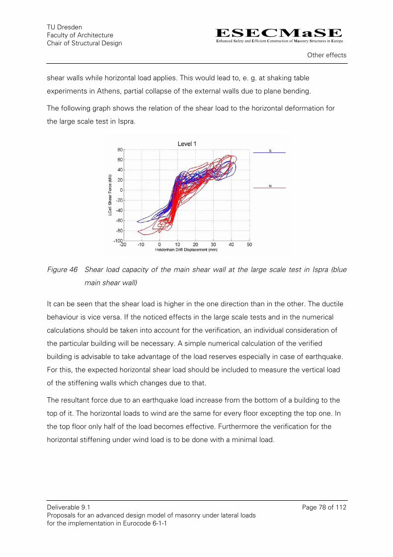
ESECMaSEEnhanced Safety and Efficient Construction of Masonry Structures in Europe
TU Dresden Faculty of Architecture Chair of Structural Design
Other effects
Deliverable 9.1 Page 78 of 112 Proposals for an advanced design model of masonry under lateral loads for the implementation in Eurocode 6-1-1
shear walls while horizontal load applies. This would lead to, e. g. at shaking table
experiments in Athens, partial collapse of the external walls due to plane bending.
The following graph shows the relation of the shear load to the horizontal deformation for
the large scale test in Ispra.
Figure 46 Shear load capacity of the main shear wall at the large scale test in Ispra (blue
main shear wall)
It can be seen that the shear load is higher in the one direction than in the other. The ductile
behaviour is vice versa. If the noticed effects in the large scale tests and in the numerical
calculations should be taken into account for the verification, an individual consideration of
the particular building will be necessary. A simple numerical calculation of the verified
building is advisable to take advantage of the load reserves especially in case of earthquake.
For this, the expected horizontal shear load should be included to measure the vertical load
of the stiffening walls which changes due to that.
The resultant force due to an earthquake load increase from the bottom of a building to the
top of it. The horizontal loads to wind are the same for every floor excepting the top one. In
the top floor only half of the load becomes effective. Furthermore the verification for the
horizontal stiffening under wind load is to be done with a minimal load.
ESECMaSEEnhanced Safety and Efficient Construction of Masonry Structures in Europe
TU Dresden Faculty of Architecture Chair of Structural Design
Material properties
Deliverable 9.1 Page 79 of 112 Proposals for an advanced design model of masonry under lateral loads for the implementation in Eurocode 6-1-1
Figure 47 Schematic comparison of the resultant force at the earthquake design and under
wind load
But there is a significant difference for the verification. While the stiffening wall at the top is
less risky at wind load, the top floor can be more loaded under earthquake load due to the
lower vertical load.
8. Material properties
Only two different material properties are needed for the proposed shear model in [19]: the
sliding coefficient and the tensile strength of the units.
The properties still used in some standardisation codes are listed in chapter 2. However, the
initial shear strength and the tensile strength are also required for the extended proposal in
this report. The compressive strength of masonry is already regulated in all masonry
standards and therefore should not be considered separately.
8.1. Tensile bond strength
The tensile bond strength is a strong scattering material parameter with only few statistic
evaluable test data.
In German standard the approach of a tensile strength perpendicular to the bed joints is
generally not permitted. This means that a verification of non-loadbearing walls without
ESECMaSEEnhanced Safety and Efficient Construction of Masonry Structures in Europe
TU Dresden Faculty of Architecture Chair of Structural Design
Material properties
Deliverable 9.1 Page 80 of 112 Proposals for an advanced design model of masonry under lateral loads for the implementation in Eurocode 6-1-1
vertical load, infill walls for example, is not possible directly. However, the regulation for the
yet allowed infill sections implies a certain tensile strength.
EC-6 includes a proposal for the bending tensile strength (see Table 5), but in the respective
National Annex it can be defined differently.
A compilation of test results shows Table 6 c in [32]. The range of values fluctuate for a
small number of tests per material combination between 0.07 N/mm² for perforated clay
units with light weight mortar and 0.67 N/mm² for CS-units with thin-layer mortar. Masonry
with light weight mortar generally achieves the lowest values.
For the optimised CS-units developed within the ESECMaSE-project the tensile bond
strength was determined in [9]. Mean values between 0.26 and 0.35 N/mm² were indicated
for the different test series. The bending tensile strength of the bond was also determined.
This was higher by a factor of 1.77 within the test series A, but is only valid for a specimen
height of 40mm. On a larger lever arm as in shear walls, the tensile strength and the
bending tensile strength are nearly equal.
As can be seen in Deliverable 5.5 [34], the bending tensile strength of the bond determined
with the 4-point-bending test and with the bond wrench test is larger than the tensile bond
strength which is determined with a axial test. The identified tensile bond strength of CS
(0.20 N/mm² for d=115mm and 0.24N/mm² for d=175mm) is located somewhat below the
level determined in [9]. For clay bricks arose values of 0.23 N/mm² (d=115mm) and 0.16
N/mm² (d=175mm). However, the values of at least 3 of 12 test lays under the level of the
characteristic values of the EC 6 (see Table 5). Both investigations ([9] and [34]) dealt only
with thin layer mortar.
Whether the specified values for the bending tensile strength in EC6 are applied also for the
tensile bond strength, then a lower value must be defined in the standard for hollow bricks.
For this, however, further investigations with different units are necessary.
It is suggested to differentiate the index of the variables too, because the bending tensile
strength perpendicular to the bed joints can reach a much larger value than the tensile bond
strength. For the bending tensile strength it is still fx1 and for tensile bond strength ft.
ESECMaSEEnhanced Safety and Efficient Construction of Masonry Structures in Europe
TU Dresden Faculty of Architecture Chair of Structural Design
Material properties
Deliverable 9.1 Page 81 of 112 Proposals for an advanced design model of masonry under lateral loads for the implementation in Eurocode 6-1-1
8.2. Sliding coefficient and initial shear strength
From the standards presented at the beginning of this report several classifications are
conducted during the normative regulation of the initial shear strength. Whereas the
Australian Standard (AS) defines the initial shear strength with the bending tensile strength
and two further limiting values, according to the German standard the initial shear strength is
addicted to the type of mortar. The EN 1996-1-1 differentiates between unit type as well as
mortar type.
According to the German standard the friction coefficient is 0.6. This applies, however, only
for loading out of plane. Corresponding to the theory of Mann/Müller a reduced friction
coefficient is specified with a value of 0.4 for shear walls. The values for the initial shear
strength were reduced with the same reduction ratio (see chapter 2.3). The reduction ratio is
1.65. In EC6 the friction coefficient for the initial shear strength is also 0.4. On the other
hand, the AS 3700 differentiates between general masonry and masonry made up of
aerated concrete (AAC) as well as different separation layers (cp. Table 2).
Table 17 shows a comparison between the shear strength defined in standards and in
values from the literature.
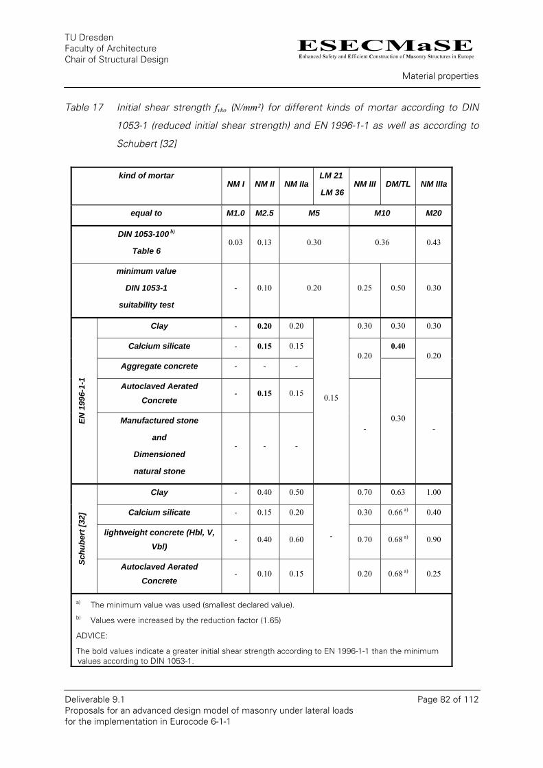
ESECMaSEEnhanced Safety and Efficient Construction of Masonry Structures in Europe
TU Dresden Faculty of Architecture Chair of Structural Design
Material properties
Deliverable 9.1 Page 82 of 112 Proposals for an advanced design model of masonry under lateral loads for the implementation in Eurocode 6-1-1
Table 17 Initial shear strength fvko (N/mm²) for different kinds of mortar according to DIN
1053-1 (reduced initial shear strength) and EN 1996-1-1 as well as according to
Schubert [32]
kind of mortar NM I NM II NM IIa
LM 21
LM 36 NM III DM/TL NM IIIa
equal to M1.0 M2.5 M5 M10 M20
DIN 1053-100 b)
Table 6 0.03 0.13 0.30 0.36 0.43
minimum value
DIN 1053-1
suitability test
- 0.10 0.20 0.25 0.50 0.30
Clay - 0.20 0.20 0.30 0.30 0.30
Calcium silicate - 0.15 0.15 0.40
Aggregate concrete - - - 0.20 0.20
Autoclaved Aerated
Concrete - 0.15 0.15
EN 1
996-
1-1
Manufactured stone
and
Dimensioned
natural stone
- - -
0.15
- 0.30
-
Clay - 0.40 0.50 0.70 0.63 1.00
Calcium silicate - 0.15 0.20 0.30 0.66 a) 0.40
lightweight concrete (Hbl, V, Vbl)
- 0.40 0.60 0.70 0.68 a) 0.90
Schu
bert
[32]
Autoclaved Aerated
Concrete - 0.10 0.15
-
0.20 0.68 a) 0.25
a) The minimum value was used (smallest declared value). b) Values were increased by the reduction factor (1.65)
ADVICE:
The bold values indicate a greater initial shear strength according to EN 1996-1-1 than the minimum values according to DIN 1053-1.

ESECMaSEEnhanced Safety and Efficient Construction of Masonry Structures in Europe
TU Dresden Faculty of Architecture Chair of Structural Design
Material properties
Deliverable 9.1 Page 83 of 112 Proposals for an advanced design model of masonry under lateral loads for the implementation in Eurocode 6-1-1
The values in Table 17 apply for filled head joints. In comparison with values from the
literature, the values of DIN 1053-100 and EC6 are on the safe side.
In [9], Brahmeshuber and Schmidt investigate for the optimized CS-units the initial shear
strength between 0.24 and 0.34 N/mm² with a thin layer mortar. However, they achieve
0.65 N/mm² with the verification according to DIN 18555-5. The static friction coefficient
was 0.54 while the dynamic friction coefficient was 0.73. The carried out torsion shear tests
also revealed an initial shear strength of 0.49 N/mm² and a static friction coefficient of 0.46.
In Deliverable 5.5 [34], values for the initial shear strength (between 0.16 and 0.24 N/mm²)
and the friction coefficient of CS-units (between 0.65 and 0.89) were indicated. For clay-
masonry the band width is between 0.08 and 0.32 N/mm² for initial shear strength and 0.58
and 0.96 for the friction coefficient.
Kirtschig and Anstötz published a proposal for the various separation layers [25]. Table 18
shows the proposed characteristical values.
An indication of the initial shear strength separated in kind of stone and mortar is necessary
for the differentiate determination of the shear strength. Therefore the appropriation of the
characteristic initial shear strength according to EN 1996-1-1 is intended for the German
National Annex. The values determined within the ESECMaSE-project are partly under the
level of EC6. Therefore a further consideration is necessary. The actual values of the EC 6
have been maintained for the shear-proposal at first.

ESECMaSEEnhanced Safety and Efficient Construction of Masonry Structures in Europe
TU Dresden Faculty of Architecture Chair of Structural Design
Material properties
Deliverable 9.1 Page 84 of 112 Proposals for an advanced design model of masonry under lateral loads for the implementation in Eurocode 6-1-1
Table 18 Characteristic initial shear strength and friction coefficient according to [25], for
damp proof course and sealing sludges
8.3. Tensile strength of the unit
By means of the cracking, which is caused by the failure due to the excess of the tensile
strength of the unit, it can be determined in which direction the tensile strength of the unit is
decisive. The longitudinal tensile strength can be applied for the usage of masonry units with
neglect of insignificant anisotropic material properties. Perforated units have a discontinuous
crack growth with diagonal cracks, as explained in [22]. The cracking starts in the smallest
cross-section (hole) and propagates along the principal stress direction. Due to this the
decisive cross-section of the unit is changing. The crack reaches a web and for this the
tensile strength of the units is increasing. This behaviour can not be adequately displayed
with conventional testing methods.
Further specific problems of the perforated clay bricks are cracks as a result of the influence
of high temperatures. Due to the firing of the bricks cracks occur, which prevent the transfer
of the tensile stresses over a couple of webs. This leads to additional bending stresses in
the rest of the webs within a centric tensile test and gives a smaller tensile strength.
ESECMaSEEnhanced Safety and Efficient Construction of Masonry Structures in Europe
TU Dresden Faculty of Architecture Chair of Structural Design
Material properties
Deliverable 9.1 Page 85 of 112 Proposals for an advanced design model of masonry under lateral loads for the implementation in Eurocode 6-1-1
The longitudinal tensile strength as an initial parameter for the calculation of the shear
capacity are significantly underestimated the experimental shear load capacity.
In Deliverable 4.4 [20] the used tensile strength of the units was calculated for perforated
clay units. For the first four tests made in Kassel the calculated tensile strength is a mixture
of vertical and horizontal tensile strength. For the other units the horizontal tensile strength
was doubled.
By the proposal of Deliverable [31] the splitting test should be used to get a practical
estimation of the tensile strength of the unit. Therefore Graubner/Kranzler used these values
for the comparison in [21].
From Deliverable 5.5 [31] the following values for the splitting tensile strength of the used
material in ESECMaSE are given.
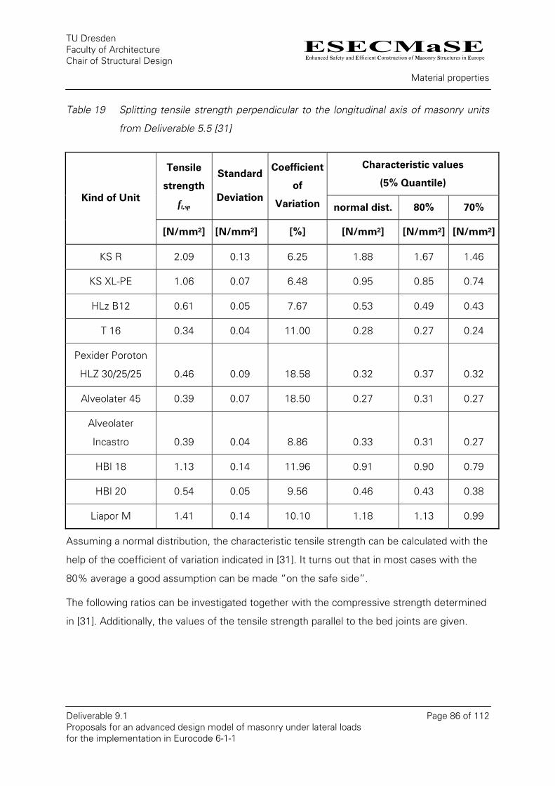
ESECMaSEEnhanced Safety and Efficient Construction of Masonry Structures in Europe
TU Dresden Faculty of Architecture Chair of Structural Design
Material properties
Deliverable 9.1 Page 86 of 112 Proposals for an advanced design model of masonry under lateral loads for the implementation in Eurocode 6-1-1
Table 19 Splitting tensile strength perpendicular to the longitudinal axis of masonry units
from Deliverable 5.5 [31]
Characteristic values
(5% Quantile)
Tensile
strength
ft,sp
Standard
Deviation
Coefficient
of
Variation normal dist. 80% 70% Kind of Unit
[N/mm²] [N/mm²] [%] [N/mm²] [N/mm²] [N/mm²]
KS R 2.09 0.13 6.25 1.88 1.67 1.46
KS XL-PE 1.06 0.07 6.48 0.95 0.85 0.74
HLz B12 0.61 0.05 7.67 0.53 0.49 0.43
T 16 0.34 0.04 11.00 0.28 0.27 0.24
Pexider Poroton
HLZ 30/25/25 0.46 0.09 18.58 0.32 0.37 0.32
Alveolater 45 0.39 0.07 18.50 0.27 0.31 0.27
Alveolater
Incastro 0.39 0.04 8.86 0.33 0.31 0.27
HBl 18 1.13 0.14 11.96 0.91 0.90 0.79
HBl 20 0.54 0.05 9.56 0.46 0.43 0.38
Liapor M 1.41 0.14 10.10 1.18 1.13 0.99
Assuming a normal distribution, the characteristic tensile strength can be calculated with the
help of the coefficient of variation indicated in [31]. It turns out that in most cases with the
80% average a good assumption can be made “on the safe side”.
The following ratios can be investigated together with the compressive strength determined
in [31]. Additionally, the values of the tensile strength parallel to the bed joints are given.
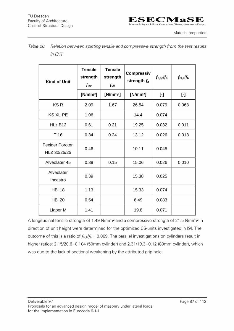
ESECMaSEEnhanced Safety and Efficient Construction of Masonry Structures in Europe
TU Dresden Faculty of Architecture Chair of Structural Design
Material properties
Deliverable 9.1 Page 87 of 112 Proposals for an advanced design model of masonry under lateral loads for the implementation in Eurocode 6-1-1
Table 20 Relation between splitting tensile and compressive strength from the test results
in [31]
Tensile strength
ft,sp
Tensile strength
ft,II
Compressiv strength fb
fb,sp/fb fbt,II/fbKind of Unit
[N/mm²] [N/mm²] [N/mm²] [-] [-]
KS R 2.09 1.67 26.54 0.079 0.063
KS XL-PE 1.06 14.4 0.074
HLz B12 0.61 0.21 19.25 0.032 0.011
T 16 0.34 0.24 13.12 0.026 0.018
Pexider Poroton
HLZ 30/25/25 0.46 10.11 0.045
Alveolater 45 0.39 0.15 15.06 0.026 0.010
Alveolater
Incastro 0.39 15.38 0.025
HBl 18 1.13 15.33 0.074
HBl 20 0.54 6.49 0.083
Liapor M 1.41 19.8 0.071
A longitudinal tensile strength of 1.49 N/mm² and a compressive strength of 21.5 N/mm² in
direction of unit height were determined for the optimized CS-units investigated in [9]. The
outcome of this is a ratio of fbt,II/fb = 0.069. The parallel investigations on cylinders result in
higher ratios: 2.15/20.6=0.104 (50mm cylinder) and 2.31/19.3=0.12 (80mm cylinder), which
was due to the lack of sectional weakening by the attributed grip hole.
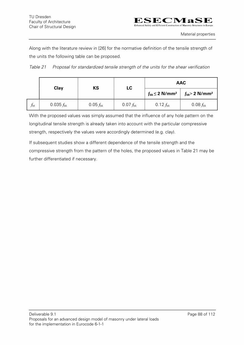
ESECMaSEEnhanced Safety and Efficient Construction of Masonry Structures in Europe
TU Dresden Faculty of Architecture Chair of Structural Design
Material properties
Deliverable 9.1 Page 88 of 112 Proposals for an advanced design model of masonry under lateral loads for the implementation in Eurocode 6-1-1
Along with the literature review in [26] for the normative definition of the tensile strength of
the units the following table can be proposed.
Table 21 Proposal for standardized tensile strength of the units for the shear verification
AAC Clay KS LC
fbk ≤ 2 N/mm² fbk> 2 N/mm²
fbt 0.035 fbk 0.05 fbk 0.07 fbk 0.12 fbk 0.08 fbk
With the proposed values was simply assumed that the influence of any hole pattern on the
longitudinal tensile strength is already taken into account with the particular compressive
strength, respectively the values were accordingly determined (e.g. clay).
If subsequent studies show a different dependence of the tensile strength and the
compressive strength from the pattern of the holes, the proposed values in Table 21 may be
further differentiated if necessary.
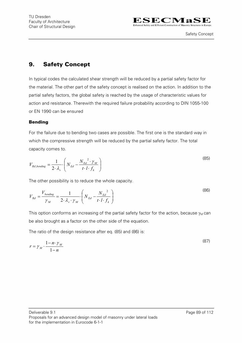
ESECMaSEEnhanced Safety and Efficient Construction of Masonry Structures in Europe
TU Dresden Faculty of Architecture Chair of Structural Design
Safety Concept
Deliverable 9.1 Page 89 of 112 Proposals for an advanced design model of masonry under lateral loads for the implementation in Eurocode 6-1-1
9. Safety Concept
In typical codes the calculated shear strength will be reduced by a partial safety factor for
the material. The other part of the safety concept is realised on the action. In addition to the
partial safety factors, the global safety is reached by the usage of characteristic values for
action and resistance. Therewith the required failure probability according to DIN 1055-100
or EN 1990 can be ensured
Bending
For the failure due to bending two cases are possible. The first one is the standard way in
which the compressive strength will be reduced by the partial safety factor. The total
capacity comes to.
⎟⎟⎠
⎞⎜⎜⎝
⎛
⋅⋅⋅
−⋅⋅
=k
MEdEd
vbendingRd flt
NNV γλ
2
, 21
(85)
The other possibility is to reduce the whole capacity.
⎟⎟⎠
⎞⎜⎜⎝
⎛
⋅⋅−⋅
⋅⋅==
k
EdEd
MvM
bendingRd flt
NN
VV
2
21
γλγ
(86)
This option conforms an increasing of the partial safety factor for the action, because γM can
be also brought as a factor on the other side of the equation.
The ratio of the design resistance after eq. (85) and (86) is:
nn
r MM −
⋅−⋅=
11 γ
γ (87)
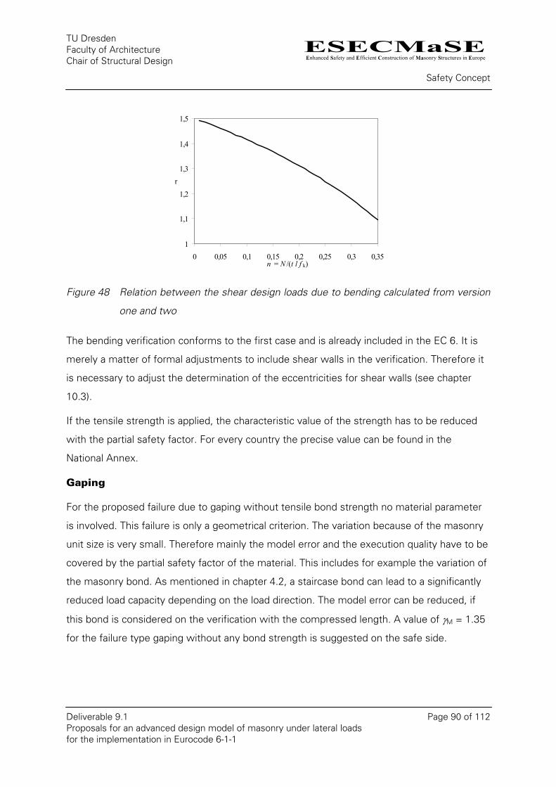
ESECMaSEEnhanced Safety and Efficient Construction of Masonry Structures in Europe
TU Dresden Faculty of Architecture Chair of Structural Design
Safety Concept
Deliverable 9.1 Page 90 of 112 Proposals for an advanced design model of masonry under lateral loads for the implementation in Eurocode 6-1-1
1
1,1
1,2
1,3
1,4
1,5
0 0,05 0,1 0,15 0,2 0,25 0,3 0,35n = N /(t l f k)
r
Figure 48 Relation between the shear design loads due to bending calculated from version
one and two
The bending verification conforms to the first case and is already included in the EC 6. It is
merely a matter of formal adjustments to include shear walls in the verification. Therefore it
is necessary to adjust the determination of the eccentricities for shear walls (see chapter
10.3).
If the tensile strength is applied, the characteristic value of the strength has to be reduced
with the partial safety factor. For every country the precise value can be found in the
National Annex.
Gaping
For the proposed failure due to gaping without tensile bond strength no material parameter
is involved. This failure is only a geometrical criterion. The variation because of the masonry
unit size is very small. Therefore mainly the model error and the execution quality have to be
covered by the partial safety factor of the material. This includes for example the variation of
the masonry bond. As mentioned in chapter 4.2, a staircase bond can lead to a significantly
reduced load capacity depending on the load direction. The model error can be reduced, if
this bond is considered on the verification with the compressed length. A value of γM = 1.35
for the failure type gaping without any bond strength is suggested on the safe side.
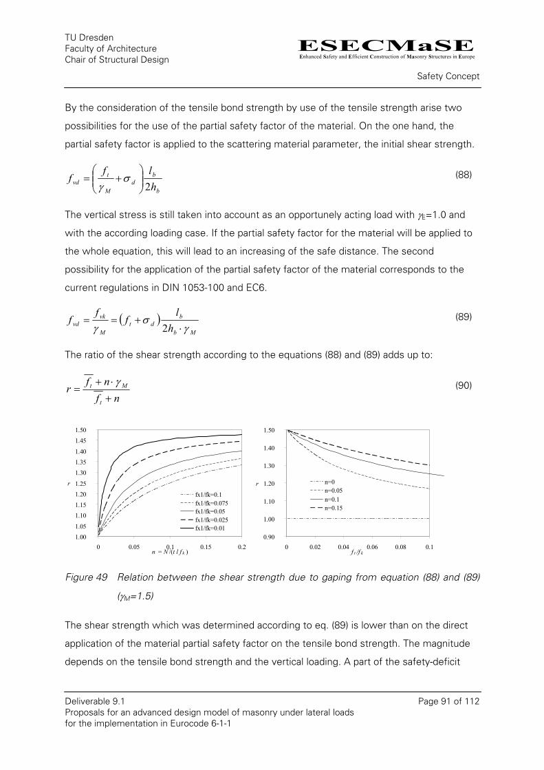
ESECMaSEEnhanced Safety and Efficient Construction of Masonry Structures in Europe
TU Dresden Faculty of Architecture Chair of Structural Design
Safety Concept
Deliverable 9.1 Page 91 of 112 Proposals for an advanced design model of masonry under lateral loads for the implementation in Eurocode 6-1-1
By the consideration of the tensile bond strength by use of the tensile strength arise two
possibilities for the use of the partial safety factor of the material. On the one hand, the
partial safety factor is applied to the scattering material parameter, the initial shear strength.
b
bd
M
tvd h
lff
2⎟⎟⎠
⎞⎜⎜⎝
⎛+= σ
γ (88)
The vertical stress is still taken into account as an opportunely acting load with γE=1.0 and
with the according loading case. If the partial safety factor for the material will be applied to
the whole equation, this will lead to an increasing of the safe distance. The second
possibility for the application of the partial safety factor of the material corresponds to the
current regulations in DIN 1053-100 and EC6.
( )Mb
bdt
M
vkvd h
lf
ff
γσ
γ ⋅+==
2 (89)
The ratio of the shear strength according to the equations (88) and (89) adds up to:
nfnf
rt
Mt
+⋅+
=γ
(90)
1.00 1.05
1.10 1.15 1.20 1.25
1.30 1.35 1.40
1.45 1.50
0 0.05 0.1 0.15 0.2n = N /(t l f k )
r
fx1/fk=0.1fx1/fk=0.075fx1/fk=0.05fx1/fk=0.025fx1/fk=0.01
0.90
1.00
1.10
1.20
1.30
1.40
1.50
0 0.02 0.04 0.06 0.08 0.1f t /f k
r n=0n=0.05n=0.1n=0.15
Figure 49 Relation between the shear strength due to gaping from equation (88) and (89)
(γM=1.5)
The shear strength which was determined according to eq. (89) is lower than on the direct
application of the material partial safety factor on the tensile bond strength. The magnitude
depends on the tensile bond strength and the vertical loading. A part of the safety-deficit
ESECMaSEEnhanced Safety and Efficient Construction of Masonry Structures in Europe
TU Dresden Faculty of Architecture Chair of Structural Design
Safety Concept
Deliverable 9.1 Page 92 of 112 Proposals for an advanced design model of masonry under lateral loads for the implementation in Eurocode 6-1-1
which occurs with an asymmetric overlapping length can thereby be compensated as can be
seen in Figure 14 in chapter 4.2. However, with an asymmetric overlapping length and
without vertical loads the shear strength still can be overestimated. Staircase bonds should
either not be allowed, or be considered via eq. (53). Another security benefit can be
achieved by the use of the tensile bond strength instead of the bending tensile strength of
the bond. Because the decreasing factor for this value is 1.3 to 2.0.
Friction/sliding
Both terms of the design equation contains a material depending factor. The initial shear
strength as well as the coefficient of friction are scattered material parameters. Due to this
the safety factor for the material has to be applied to the whole equation. A variation, like the
one for gaping, is not possible.
Tensile failure of the unit
Similar to the gaping the partial safety factor for the material will be related to the shear
strength and alternatively to the tensile strength of the units in the following. If only the
tensile strength of the unit should be reduced by the safety factor the shear load capacity
becomes to:
ltfNf
cltV
bt
EdM
M
btRd ⋅⋅⋅
⋅+⋅
⋅⋅
=βγ
γα 1 (91)
If the partial safety factor is considered for total shear the equation result to:
ltfN
fc
ltVbt
Edbt
MRd ⋅⋅⋅
+⋅⋅⋅
=β
αγ
1 (92)
The ratio of the shear capacity according to the equations (91) and (92) are:
bt
bt
M
fnfn
r
⋅+
⋅⋅
+
=
β
βγ
1
1 (93)
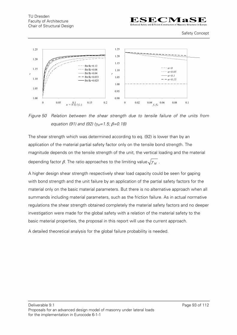
ESECMaSEEnhanced Safety and Efficient Construction of Masonry Structures in Europe
TU Dresden Faculty of Architecture Chair of Structural Design
Safety Concept
Deliverable 9.1 Page 93 of 112 Proposals for an advanced design model of masonry under lateral loads for the implementation in Eurocode 6-1-1
1.00
1.05
1.10
1.15
1.20
1.25
0 0.05 0.1 0.15 0.2n = N /(t l f k )
r
fbt/fk=0.12fbt/fk=0.08fbt/fk=0.04fbt/fk=0.033fbt/fk=0.025
0.90
0.95
1.00
1.05
1.10
1.15
1.20
1.25
0 0.02 0.04 0.06 0.08 0.1f t /f k
r
n=0n=0.05n=0.1n=0.15
Figure 50 Relation between the shear strength due to tensile failure of the units from
equation (91) and (92) (γM=1.5; β=0.18)
The shear strength which was determined according to eq. (92) is lower than by an
application of the material partial safety factor only on the tensile bond strength. The
magnitude depends on the tensile strength of the unit, the vertical loading and the material
depending factor β. The ratio approaches to the limiting value Mγ .
A higher design shear strength respectively shear load capacity could be seen for gaping
with bond strength and the unit failure by an application of the partial safety factors for the
material only on the basic material parameters. But there is no alternative approach when all
summands including material parameters, such as the friction failure. As in actual normative
regulations the shear strength obtained completely the material safety factors and no deeper
investigation were made for the global safety with a relation of the material safety to the
basic material properties, the proposal in this report will use the current approach.
A detailed theoretical analysis for the global failure probability is needed.
ESECMaSEEnhanced Safety and Efficient Construction of Masonry Structures in Europe
TU Dresden Faculty of Architecture Chair of Structural Design
Proposal for the EC 6
Deliverable 9.1 Page 94 of 112 Proposals for an advanced design model of masonry under lateral loads for the implementation in Eurocode 6-1-1
10. Proposal for the EC 6
The proposed indexing differs slightly from the current designations. A standardisation shall
be carried out in the corresponding normative committees. For example the tensile strength
of the unit is not yet regulated in the Eurocode. The bending tensile strength for masonry
perpendicular to the bed joints, which is essentially corresponding to the bending tensile
strength of the bond, is defined as fx1. The tensile bond strength, required for the failure due
to gaping, is defined by ft.
10.1. Shear verification on the basis of shear load capacity
The formulation in chapter 6.2 should be changed to:
6.2 Unreinforced masonry walls subjected to shear loading
(1)P At the ultimate limit state the design value of the shear load applied to the masonry wall, VEd, shall
be less than or equal to the design value of the shear resistance of the wall, VRd, such that :
RdEd VV ≤ (6.12)
(1) The design value of the shear resistance is given by the minimum of:
⎟⎟⎠
⎞⎜⎜⎝
⎛ −+=
hll
hlNV olb
b
ol
M
EdRd γ
(6.13a)
M
EdRd
NV
γµ ⋅
= (6.13b)
calbt
Edbt
M
calRd ltf
Nf
clt
V⋅⋅
⋅+⋅
⋅⋅
=5
122.0γ
(6.13c)
calbt
Edbt
M
calRd ltf
Nf
clt
V⋅⋅
⋅+⋅
⋅⋅
=16
11.0γ
for AAC-masonry
where:
ESECMaSEEnhanced Safety and Efficient Construction of Masonry Structures in Europe
TU Dresden Faculty of Architecture Chair of Structural Design
Proposal for the EC 6
Deliverable 9.1 Page 95 of 112 Proposals for an advanced design model of masonry under lateral loads for the implementation in Eurocode 6-1-1
t is the thickness of the wall resisting the shear;
h is the height of the wall;
hb is the height of the masonry unit;
lb is the length of the masonry unit;
lol is the overlapping length of the masonry bond, for a regular bond it could be taken half of the unit length;
lcal is the calculated length of the wall see clause (6);
γM for eq. (6.13a) a partial safety factor of 1.35 could be used, if the size of the units and the overlapping length is fixed. In the other case 1.35 has to be used.
µ is the friction coefficient; For typical masonry a value of 0.6 could be used. For dry masonry the value should be 0.4. Damp-proof courses or other material affecting the sliding should be taken into account;
fbt is the characteristic tensile strength of the unit;
fbk is the characteristic compressive strength of the unit;
α is a factor to consider the shear stress distribution in the unit and the wall.
c is the factor to consider the shear distribution at the cross section; c = 1.0 ≤ 0.5+λv ≤ 1.5;
λv is the shear slendernesslh
v ⋅=ψλ , with ψ = 1.0 for cantilever systems and
ψ = 0.5 for full restraint walls.
(2) For masonry with filled heat joint eq. (6.13a) don’t need to be used.
(3)The characteristic tensile strength of the unit, fbt, may be determined from either:
the evaluation of a database on the results of splitting tests on the tensile strength of masonry units,
or
from the values given in ….
(4)P The connections between shear walls and flanges of intersecting walls shall be verified for
vertical shear.
ESECMaSEEnhanced Safety and Efficient Construction of Masonry Structures in Europe
TU Dresden Faculty of Architecture Chair of Structural Design
Proposal for the EC 6
Deliverable 9.1 Page 96 of 112 Proposals for an advanced design model of masonry under lateral loads for the implementation in Eurocode 6-1-1
(6) The calculated length of a wall may be taken from equation (6.14)
iniEd
Edinical el
NhV
ell 22133
23
−≤⎟⎠⎞
⎜⎝⎛ −−−= ψ (6.14)
where:
eini is the initial eccentricity of the vertical loads at the top of the wall;
h is the height of the wall;
l is the length of the wall;
ψ is a factor for the consideration of restraining effects at the top of the wall, the value should be chosen between 0.5 for a full restrained system and 1.0 for a cantilever system.
(5) The length of the compressed part of the wall should be verified for the vertical loading applied to
it and the vertical load effect of the shear loads.
10.2. Shear verification on the basis of shear strength
The formulation in chapter 6.2 should be changed to:
6.2 Unreinforced masonry walls subjected to shear loading
(1)P At the ultimate limit state the design value of the shear load applied to the masonry wall, VEd, shall
be less than or equal to the design value of the shear resistance of the wall, VRd, such that :
RdEd VV ≤ (6.12)
(2) The design value of the shear resistance is given by the minimum of the shear resistance due to
gaping, friction and unit failure :
calvd
Rd ltcf
V = (6.13b)
where:
fvd is the design value of the shear strength of masonry, obtained from 2.4.1 and 3.6.2, based on the average of the vertical stresses over the compressed part of
ESECMaSEEnhanced Safety and Efficient Construction of Masonry Structures in Europe
TU Dresden Faculty of Architecture Chair of Structural Design
Proposal for the EC 6
Deliverable 9.1 Page 97 of 112 Proposals for an advanced design model of masonry under lateral loads for the implementation in Eurocode 6-1-1
the wall that is providing the shear resistance;
t is the thickness of the wall resisting the shear;
lcal is the calculated length of the wall, in case of gaping of the unit and friction the calculated length is identical to the length of the compressed part of the wall lc; For shear strength due to tensile failure of the units see clause (5).
c is the factor to consider the shear distribution at the cross section; c = 1.0 ≤ 0.5+λv ≤ 1.5;
λv is the shear slenderness lh
v ⋅=ψλ , with ψ = 1.0 for cantilever systems and
ψ = 0.5 for full restraint walls.
(3) The length of the compressed part of the wall, lc, should be calculated assuming a linear stress
distribution of the compressive stresses, and taking into account any openings, chases or recesses; any
portion of the wall subjected to vertical tensile stresses should not be used in calculating the area of
the wall to resist shear.
(4)P The connections between shear walls and flanges of intersecting walls shall be verified for
vertical shear.
(5) The calculated length of a wall may be taken from equation (6.14)
iniEd
Edinical el
NhV
ell 22133
23
−≤⎟⎠⎞
⎜⎝⎛ −−−= ψ (6.14)
where:
eini is the initial eccentricity of the vertical loads at the top of the wall;
h is the height of the wall;
l is the length of the wall;
ψ is a factor for the consideration of restraining effects at the top of the wall, the value should be chosen between 0.5 for a full restrained system and 1.0 for a cantilever system.
(6) The length of the compressed part of the wall should be verified for the vertical loading applied to
it and the vertical load effect of the shear loads.
ESECMaSEEnhanced Safety and Efficient Construction of Masonry Structures in Europe
TU Dresden Faculty of Architecture Chair of Structural Design
Proposal for the EC 6
Deliverable 9.1 Page 98 of 112 Proposals for an advanced design model of masonry under lateral loads for the implementation in Eurocode 6-1-1
The formulation in chapter 3.6.2 should be changed to:
3.6.2 Characteristic shear strength of masonry
(1)P The characteristic shear strength of masonry, fvk, shall be determined from the results of tests on
masonry.
(2) The characteristic shear strength of masonry, fvk, due to gaping of single units or struts using
general purpose mortar in accordance with 3.2.2(2), or thin layer mortar in beds of thickness 0,5 mm
to 3,0 mm, in accordance with 3.2.2(3), or lightweight mortar in accordance with 3.2.2(4) with all
joints satisfying the requirements of 8.1.5, may be taken from equation (3.5).
( )b
oldtvk h
lff σ+= (3.5a)
where:
hb is the height of the masonry unit;
lb is the length of the masonry unit;
lol is the overlapping length of the masonry bond, for a regular bond it could be taken half of the unit length;
σd is the design compressive stress perpendicular to the shear in the member at the level under consideration, using the appropriate load combination based on the average vertical stress over the compressed part of the wall that is providing shear resistance;
ft is the characteristic tensile bond strength.
(3)The tensile bond strength of the masonry, ft, may be determined from either:
the evaluation of a database on the results of tests on the tensile bond strength of masonry,
or
by calculating from the values for bending strength perpendicular to the bed joints given in chapter
3.6.3 by ft = fx1/ 1.5
(4) The characteristic shear strength of masonry, fvk, due to friction using general purpose mortar in
accordance with 3.2.2(2), or thin layer mortar in beds of thickness 0,5 mm to 3,0 mm, in accordance
ESECMaSEEnhanced Safety and Efficient Construction of Masonry Structures in Europe
TU Dresden Faculty of Architecture Chair of Structural Design
Proposal for the EC 6
Deliverable 9.1 Page 99 of 112 Proposals for an advanced design model of masonry under lateral loads for the implementation in Eurocode 6-1-1
with 3.2.2(3), or lightweight mortar in accordance with 3.2.2(4) with all joints satisfying the
requirements of 8.1.5, may be taken from equation (3.5).
dvkovk 4,0 σ+= ff (3.5)
where:
fvko is the characteristic initial shear strength, under zero compressive stress; the perpend joints unfilled, but with adjacent faces of the masonry units closely abutted together, fvko have to divide in half;
(5) In shell bedded masonry, where the units are bedded on two or more equal strips of general
purpose mortar, the initial shear strength fvko has to be reduced by the relation of the width of the
stripes to the width of the wall.
(6) The characteristic initial shear strength of masonry, fvko, should be determined from tests in
accordance with EN 1052-3 or EN 1052-4.
(7)The initial shear strength of the masonry, fvko, may be determined from either:
the evaluation of a database on the results of tests on the initial shear strength of masonry,
or
from the values given in table 3.4, provided that general purpose mortars made in accordance with EN 1996-2 do not contain admixtures or additives.
(8) The characteristic shear strength of masonry, fvk, due to tensile failure of the units, may be taken
from equation (3.6)
bt
dbtvk f
ffσ
5122.0 +⋅= (3.6a)
bt
dbtvk f
ffσ
1611.0 +⋅= for AAC-masonry (3.6b)
where:
σd is the design compressive stress perpendicular to the shear in the member at the level under consideration, using the appropriate load combination based on the average vertical stress over the calculated length of the wall that is providing shear resistance;
ESECMaSEEnhanced Safety and Efficient Construction of Masonry Structures in Europe
TU Dresden Faculty of Architecture Chair of Structural Design
Proposal for the EC 6
Deliverable 9.1 Page 100 of 112 Proposals for an advanced design model of masonry under lateral loads for the implementation in Eurocode 6-1-1
fbt is the characteristic tensile strength of the unit;
fbk is the characteristic compressive strength of the unit;
α is a factor to consider the shear stress distribution in the unit and the wall.
(9) The characteristic tensile strength of the unit, fbt, may be determined from either:
the evaluation of a database on the results of splitting tests on the tensile strength of masonry units,
or
from the values given in ….
10.3. Bending
The formulation in chapter 6.1.2.1 clause 2 should be changed to:
(2) The design value of the vertical resistance of a single leaf, NRd, is given by:
dRd ftN Φ= (6.2)
where:
Φ is the capacity reduction factor, Φi, at the top or bottom of the wall, or Φm, in the middle of the wall, as appropriate, allowing for the effects of slenderness and eccentricity of loading in or out of plane, obtained from 6.1.2.2;
t is the thickness of the wall or in case of shear walls, the length of the wall;
fd is the design compressive strength of the masonry, obtained from 2.4.1 and 3.6.1.
NOTE For the out of plane eccentricity the verification should be made per unit length.

ESECMaSEEnhanced Safety and Efficient Construction of Masonry Structures in Europe
TU Dresden Faculty of Architecture Chair of Structural Design
Proposal for the EC 6
Deliverable 9.1 Page 101 of 112 Proposals for an advanced design model of masonry under lateral loads for the implementation in Eurocode 6-1-1
6.1.2.2 Reduction factor for slenderness and eccentricity
(1) The value of the reduction factor for slenderness and eccentricity, �, may be based on a rectangular
stress block as follows:
(i) At the top or bottom of the wall (Φi)
tei
i 21 −=Φ (6.4)
where:
ei is the eccentricity at the top or the bottom of the wall, as appropriate, calculated using the equation (6.5) or in case of shear walls with an eccentricity in plane (6.5b):
teeNM
e 05,0initheid
idi ≥++= (6.5)
initid
i eN
hVe calEd +
⋅= (6.5b)
Mid is the design value of the bending moment at the top or the bottom of the wall resulting from the eccentricity of the floor load at the support, analysed according to 5.5.1 (see figure 6.1);
VEd is the design value of the horizontal load at the top of the wall;
Nid is the design value of the vertical load at the top or bottom of the wall;
ehe is the eccentricity at the top or bottom of the wall, if any, resulting from horizontal loads (for example, wind);
einit is the initial eccentricity (see 5.5.1.1);
hcal calculated height of a wall;
t is the thickness of the wall.
In case of a restraint support at the top of the wall ;
hhcal ⋅=ψ
ψ is a factor for the consideration of restraining effects at the top of the wall, the value should be chosen between 0.5 for a full restrained system and 1.0 for a cantilever
ESECMaSEEnhanced Safety and Efficient Construction of Masonry Structures in Europe
TU Dresden Faculty of Architecture Chair of Structural Design
Proposal for the EC 6
Deliverable 9.1 Page 102 of 112 Proposals for an advanced design model of masonry under lateral loads for the implementation in Eurocode 6-1-1
system.
h clear height of a masonry wall to the level of the load;
(2) For a high initial eccentricity or a full restrained system, the vertical resistance for shear walls
should also be verified at the top of the wall.

ESECMaSEEnhanced Safety and Efficient Construction of Masonry Structures in Europe
TU Dresden Faculty of Architecture Chair of Structural Design
Comparison of the standards, the proposed Equations and test results
Deliverable 9.1 Page 103 of 112 Proposals for an advanced design model of masonry under lateral loads for the implementation in Eurocode 6-1-1
11. Comparison of the standards, the proposed Equations
and test results
11.1. Comparison of Proposal, DIN 1053-100 and EN 1996-1-1
Based on a sample wall, the proposal should be compared to the current state of the
German standard DIN 1053-100 [3] and the European standard EN 1996-1-1 [5] in the
following charts. For this the ratios subjected to the vertical loading will be presented for
modern masonry with thin layer mortar and with unfilled head joints.
Table 22 Geometric data for the comparison
ls
[m]
hs
[m]
t
[m]
l
[m]
h
[m]
0.25 0.25 0.24 2.5 2.5
Table 23 General material data for the comparison
ft [N/mm²]
fvk0 [N/mm²]
EN 1996-1-1 a 0.15 0.3 (0,4 CS)
DIN 1053-100 - 0.22b
a with the proposed amplification b reduced value
For the unit tensile strength of the proposed equations the values given in Table 21 were
used. For both standards the same partial safety factors were used for a better
comparability. These are γE = 1.5 for the actions and γE = 1.5 for the material. The wall is
considered as fully fixed (ψ = 0.5).
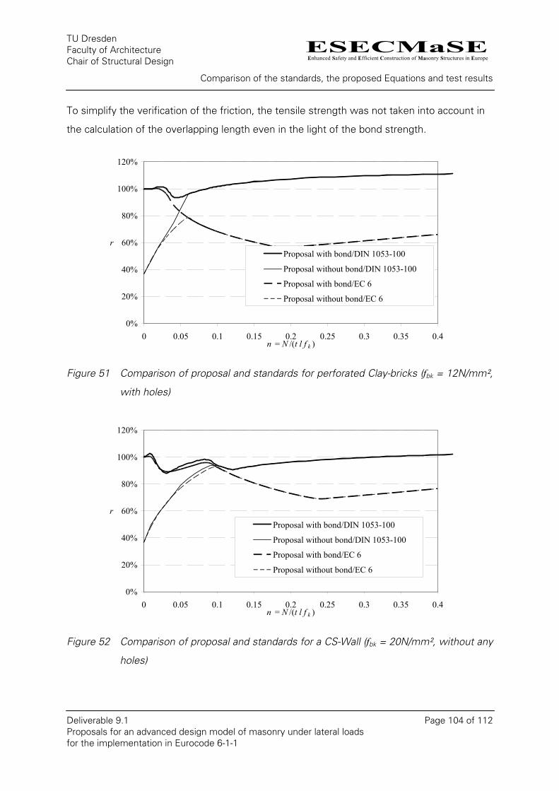
ESECMaSEEnhanced Safety and Efficient Construction of Masonry Structures in Europe
TU Dresden Faculty of Architecture Chair of Structural Design
Comparison of the standards, the proposed Equations and test results
Deliverable 9.1 Page 104 of 112 Proposals for an advanced design model of masonry under lateral loads for the implementation in Eurocode 6-1-1
To simplify the verification of the friction, the tensile strength was not taken into account in
the calculation of the overlapping length even in the light of the bond strength.
0%
20%
40%
60%
80%
100%
120%
0 0.05 0.1 0.15 0.2 0.25 0.3 0.35 0.4n = N /(t l f k )
rProposal with bond/DIN 1053-100
Proposal without bond/DIN 1053-100
Proposal with bond/EC 6
Proposal without bond/EC 6
Figure 51 Comparison of proposal and standards for perforated Clay-bricks (fbk = 12N/mm²,
with holes)
0%
20%
40%
60%
80%
100%
120%
0 0.05 0.1 0.15 0.2 0.25 0.3 0.35 0.4n = N /(t l f k )
rProposal with bond/DIN 1053-100
Proposal without bond/DIN 1053-100
Proposal with bond/EC 6
Proposal without bond/EC 6
Figure 52 Comparison of proposal and standards for a CS-Wall (fbk = 20N/mm², without any
holes)
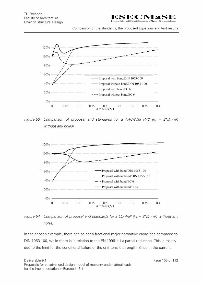
ESECMaSEEnhanced Safety and Efficient Construction of Masonry Structures in Europe
TU Dresden Faculty of Architecture Chair of Structural Design
Comparison of the standards, the proposed Equations and test results
Deliverable 9.1 Page 105 of 112 Proposals for an advanced design model of masonry under lateral loads for the implementation in Eurocode 6-1-1
0%
20%
40%
60%
80%
100%
120%
0 0.05 0.1 0.15 0.2 0.25 0.3 0.35 0.4n = N /(t l f k )
r
Proposal with bond/DIN 1053-100
Proposal without bond/DIN 1053-100
Proposal with bond/EC 6
Proposal without bond/EC 6
Figure 53 Comparison of proposal and standards for a AAC-Wall PP2 (fbk = 2N/mm²,
without any holes)
0%
20%
40%
60%
80%
100%
120%
0 0.05 0.1 0.15 0.2 0.25 0.3 0.35 0.4n = N /(t l f k )
r Proposal with bond/DIN 1053-100
Proposal without bond/DIN 1053-100
Proposal with bond/EC 6
Proposal without bond/EC 6
Figure 54 Comparison of proposal and standards for a LC-Wall (fbk = 8N/mm², without any
holes)
In the chosen example, there can be seen fractional major normative capacities compared to
DIN 1053-100, while there is in relation to the EN 1996-1-1 a partial reduction. This is mainly
due to the limit for the conditional failure of the unit tensile strength. Since in the current

ESECMaSEEnhanced Safety and Efficient Construction of Masonry Structures in Europe
TU Dresden Faculty of Architecture Chair of Structural Design
Comparison of the standards, the proposed Equations and test results
Deliverable 9.1 Page 106 of 112 Proposals for an advanced design model of masonry under lateral loads for the implementation in Eurocode 6-1-1
EC 6 it is not depending on the vertical loads, it leads for smaller loads to an overestimation
of the loading capacity.
With the chosen shear slenderness of 0.5, provided the equations a higher load capacity for
all four combinations of materials with consideration of the bond strength. For shorter walls
or larger shear slenderness even larger capacities can arise without consideration of the
bond strength, especially at friction failure, than with consideration of the bond strength.
Depending on the restraint level or length of the wall, the ratios can also vary due to the
different definition of the factor c (see Figure 37).
11.2. Comparison with test results
In the following chart the ratios between the theoretical model (with bond strength) and
experimental value (with and without safety factors) are described. The partial safety factors
are for the action as well as for the material 1.5.
0
0.2
0.4
0.6
0.8
1
1.2
1.4
1.6
0.0 0.1 0.2 0.3 0.4n = N /(t l f k )
V cal
/Vob
s
0.5
Tests ClayTests CSTests AACTests LC
Figure 55 Comparison of the test result with the theoretical model without partial safety
factors
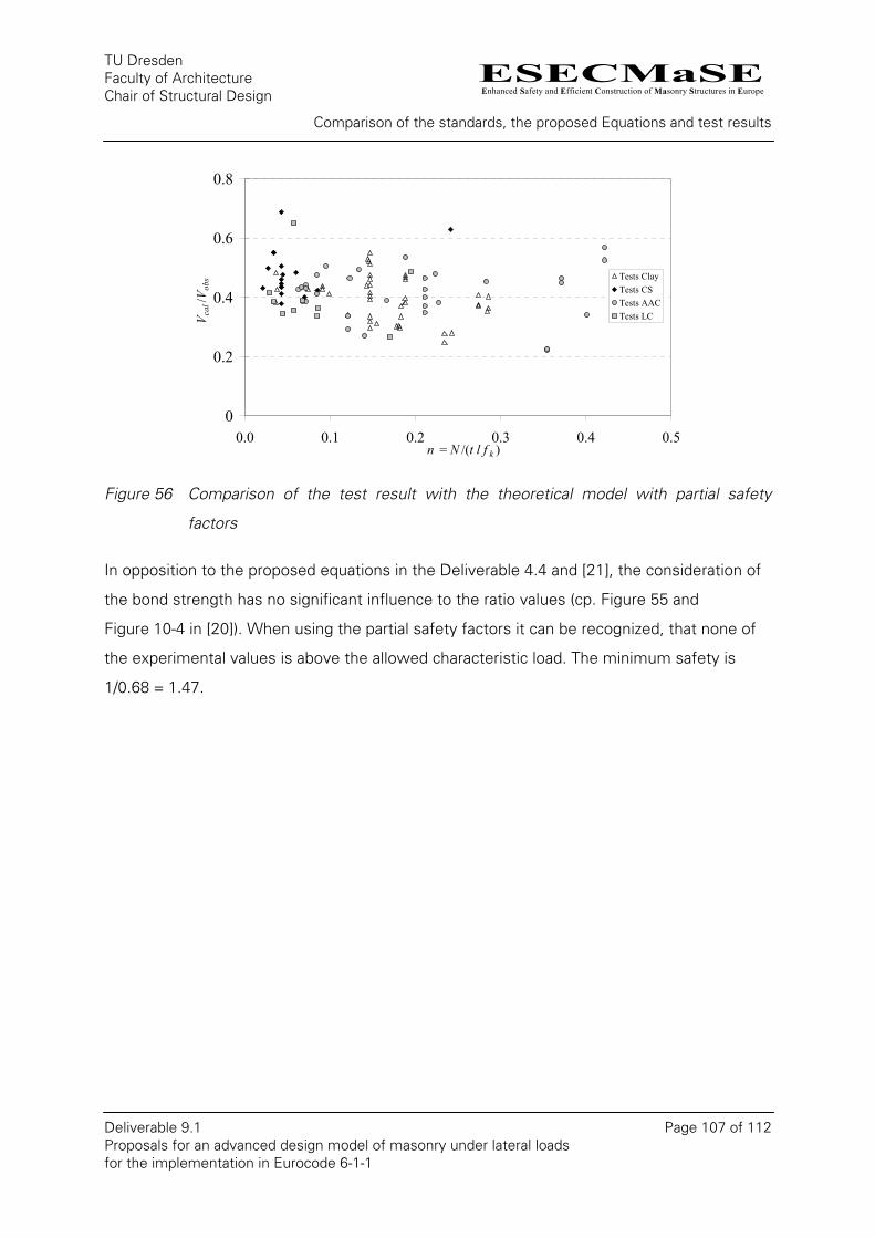
ESECMaSEEnhanced Safety and Efficient Construction of Masonry Structures in Europe
TU Dresden Faculty of Architecture Chair of Structural Design
Comparison of the standards, the proposed Equations and test results
Deliverable 9.1 Page 107 of 112 Proposals for an advanced design model of masonry under lateral loads for the implementation in Eurocode 6-1-1
0
0.2
0.4
0.6
0.8
0.0 0.1 0.2 0.3 0.4n = N /(t l f k )
V cal
/Vob
s
0.5
Tests ClayTests CSTests AACTests LC
Figure 56 Comparison of the test result with the theoretical model with partial safety
factors
In opposition to the proposed equations in the Deliverable 4.4 and [21], the consideration of
the bond strength has no significant influence to the ratio values (cp. Figure 55 and
Figure 10-4 in [20]). When using the partial safety factors it can be recognized, that none of
the experimental values is above the allowed characteristic load. The minimum safety is
1/0.68 = 1.47.
ESECMaSEEnhanced Safety and Efficient Construction of Masonry Structures in Europe
TU Dresden Faculty of Architecture Chair of Structural Design
Conclusion
Deliverable 9.1 Page 108 of 112 Proposals for an advanced design model of masonry under lateral loads for the implementation in Eurocode 6-1-1
12. Conclusion
The objective of this report is a proposal for an advanced design model of masonry under
lateral loads for the purpose of implementation in Eurocode 6-1-1 (EC6).
Therefore, various analytical and empirical models as well as the existing standards have
been discussed. An essential basis for this was the proposal from the Work Package 4 of
the ESECMaSE project. For the analytically described failure modes at the joints (gaping and
friction) an additional consideration of the bond strength was made. The equation for the
tensile failure of the units was simplified.
A text proposal for the revision of the EC 6 was given after a brief reflection of the safety
concept. The proposal was thereupon compared with the existing experimental results. It
could be established, that within the terms of the tested range, an acceptable safety margin
can be guaranteed.
For some test the relevant material data had to be taken from the literature. These values
could in fact be accurately assessed in the meantime, but the material variety and the
changing composition over the time, leads to some uncertainty.
An investigation of the overall failure probability is however needed.
A significant reserve in the design of masonry buildings against horizontal loads consists in
determining the real forces for the member in shear. Through the rearrangement of the load
distribution during the action of the wind or earthquake loads a significantly higher vertical
load for the shear walls will be reached and thus a greater shear resistance will result. The
numerical simulations and large scaled tests, which were performed in the framework of
ESECMaSE showed that circumstance.
Since the test procedure will be continuing until the end of the project, the evaluation
process will going on to the end. In particular, the interpretation of the failure shape in each
test itself will give further evidence of the influencing factors and the proposed equations.
With an increase of the data base also a distinction between Clay, CS and LC instead of a
common rule is possible.

ESECMaSEEnhanced Safety and Efficient Construction of Masonry Structures in Europe
TU Dresden Faculty of Architecture Chair of Structural Design
Conclusion
Deliverable 9.1 Page 109 of 112 Proposals for an advanced design model of masonry under lateral loads for the implementation in Eurocode 6-1-1
The confined masonry could not be discussed within this report, because no new theoretical
investigations were made and the relevant tests have not been completed or released till
now. But the results will incorporated into an ongoing project beside ESECMaSE and lead
there to an advanced design model.
ESECMaSEEnhanced Safety and Efficient Construction of Masonry Structures in Europe
TU Dresden Faculty of Architecture Chair of Structural Design
References
Deliverable 9.1 Page 110 of 112 Proposals for an advanced design model of masonry under lateral loads for the implementation in Eurocode 6-1-1
References
[1] AS 3700-2001: Masonry Structures. Standards Australia International: Sydney 2001
[2] DIN 1053-1: 1996-11, Mauerwerk. Teil 1: Berechnung und Ausführung. Deutsches Institut für Normung e.V.: Beuth Verlag Berlin 1996
[3] DIN 1053-100: 2007-09, Mauerwerk. Teil 100: Berechnung auf der Grundlage des semiprobabilistischen Sicherheitskonzepts. Deutsches Institut für Normung e.V.: Beuth Verlag Berlin 2007
[4] DIN 1055-100: 2001-03: Einwirkungen auf Tragwerke. Teil 100: Grundlagen der Tragwerksplanung, Sicherheitskonzept und Bemessungsregeln. Deutsches Institut für Normung e.V.: Beuth Verlag Berlin 2001
[5] EN 1996-1-1: Eurocode 6: Design of Masonry Structures – Part 1-1: Common rules for reinforced and unreinforced masonry structures. Deutsche Fassung. Deutsches Institut für Normung e.V.: Beuth Verlag Berlin 2006
[6] EN 1990: Basis of structural design. Deutsche Fassung. Deutsches Institut für Normung e.V.: Beuth Verlag Berlin 2002
[7] SIA 266: 2003: Mauerwerk. Schweizerischer Ingenieur- und Architektenverein: Zürich 2003
[8] Anthoine, A: Definition and design of the test specimen. Technical report D8.1 of the collective research project ESECMaSE: European Laboratory for Structural Assessment (ELSA). Joint Research Centre of the European Commission. Ispra October 2007
[9] Brameshuber, W.; Schmidt, U.: Untersuchungen zur Bestimmung von Stoffgesetzen von Kalksandsteinen und des Verbundes. Forschungsbericht F7044/1: Institut für Bauforschung. RWTH Aachen 2006
[10] Carydis, P.; Mouzakis: Static and Dynamic Shear Test on Structural Members Technical report D7 of the collective research project ESECMaSE: National Technical University of Athens, Laboratory for Earthquake Engineering: March 2007
[11] Costa, A.: Experimental testing of lateral capacity of masonry piers. An application to seismic assessment of AAC masonry buildings. Dissertation, European School for advanced studies in reduction of seismic risk: Pavia 2007
[12] Fehling, E.; Stürz, J.: Stress-strain-relation of perforated bricks (4-brick-specimen). Technical report D3.0.2 of the collective research project ESECMaSE: University of Kassel, Institut für Konstruktiven Ingenieurbau, Fachgebiet Massivbau.
[13] Fehling, E.; Stürz, J.: Stress-strain-relation of perforated bricks (Rilem-specimen). Technical report D3.0.3 of the collective research project ESECMaSE: University of Kassel, Institut für Konstruktiven Ingenieurbau, Fachgebiet Massivbau.
[14] Fehling, E.; Stürz, J.: Theoretical Investigation on Stress States of Masonry Structures Subjected to Static and Dynamic Shear Loads (Lateral Loads). Technical report D3.1 of
ESECMaSEEnhanced Safety and Efficient Construction of Masonry Structures in Europe
TU Dresden Faculty of Architecture Chair of Structural Design
References
Deliverable 9.1 Page 111 of 112 Proposals for an advanced design model of masonry under lateral loads for the implementation in Eurocode 6-1-1
the collective research project ESECMaSE: University of Kassel, Institut für Konstruktiven Ingenieurbau, Fachgebiet Massivbau. June 2005
[15] Fehling, E.; Stürz, J.: Experimentelle Untersuchungen zum Schubtragverhalten von Porenbetonwandscheiben. Forschungsbericht im Auftrag der European Autoclaved Aerated Concrete Association: University of Kassel, Institut für Konstruktiven Ingenieurbau, Fachgebiet Massivbau. November 2006
[16] Fehling, E.; Stürz, J.: Test results on the behaviour of masonry under static (monotonic and cyclic) in plane lateral loads. Technical report D7.1a of the collective research project ESECMaSE: University of Kassel, Institut für Konstruktiven Ingenieurbau, Fachgebiet Massivbau. February 2008
[17] Grabowski, S.: Material properties for the tests in WP 7 and 8 and the verification of the design model of WP 4. Technical report D5.5 of the collective research project ESECMaSE: Technical University of Munich, Department of civil engineering and geodesy, Chair of Structural Concrete. November 2005
[18] Graubner, C.-A.; Kranzler, T.: Report on specific demands for the test methods and required material properties. Technical report D4.2 of the collective research project ESECMaSE: Technische Universität Darmstadt, Institut für Massivbau. 2005
[19] Graubner, C.; Kranzler, T.: Report on the integral shear design model for structural masonry members. Technical report D4.3 of the collective research project ESECMaSE: Technische Universität Darmstadt, Institut für Massivbau. 2007
[20] Graubner, C.; Kranzler, T.: Report on the verification of the design model and its verification by experimental results. Technical report D4.4 of the collective research project ESECMaSE: Technische Universität Darmstadt, Institut für Massivbau. 2007
[21] Graubner, C.; Kranzler, T.: Integral model for the in-plane lateral-load capacity of URM (shear) bearing walls and calibration with test results. Proceedings of the 14th International Brick & Block Masonry Conference, Sydney 2008
[22] Jäger, W.; Schöps, P.: Kosteneinsparung durch Ansatz realitätsnaher Bemessungskonzepte für die Schubbeanspruchung von Mauerwerksbauten. Forschungsbericht: TU Dresden, Faculty of Architecture, Chair of Structural Design. Dresden November 2004
[23] Jäger, W.; Schöps P.: Sichtung und Vorauswertung von Schubversuchen. Forschungsbericht: TU Dresden, Faculty of Architecture, Chair of Structural Design. Dresden November 2005
[24] Jäger, W.; Schöps, P.: Shear Stress Distribution of Stiffening Walls. Proceedings of the 7th International Masonry Conference, London 2006
[25] Kirtschig, K.; Anstötz, W.: Ermittlung der Reibungsbeiwerte von Feuchtesperrschichten. Forschungsbericht: Universität Hannover, Institut für Baustoffkunde und Materialprüfung. Juli 1990
[26] Kraus, N.: Material parameters of masonry units - Input for WP 3. Technical report D5.1 of the collective research project ESECMaSE: Technical University of Munich, Department of civil engineering and geodesy, Chair of Structural Concrete. September 2004
ESECMaSEEnhanced Safety and Efficient Construction of Masonry Structures in Europe
TU Dresden Faculty of Architecture Chair of Structural Design
References
Deliverable 9.1 Page 112 of 112 Proposals for an advanced design model of masonry under lateral loads for the implementation in Eurocode 6-1-1
[27] Mann, W.; Müller, H.: Schubtragfähigkeit von Mauerwerk. Mauerwerk-Kalender 3 (1978). Ed. P. Funk. Erst und Sohn: Berlin pp. 35-65
[28] Mojsilović, N.: Zum Tragverhalten von kombiniert beanspruchtem Mauerwerk. Dissertation, ETH Zürich, Institut für Baustatik und Konstruktion: Zürich 1995
[29] Nguyen, S. H.: Festlegung der Teilsicherheitsbeiwerte für das Material. Mauerwerk-Kalender 33 (2008). Ed. W. Jäger. Erst und Sohn: Berlin pp. 527-536
[30] Schermer, D.: Analysis of Apartment House (AH). Technical report D3.2 of the collective research project ESECMaSE: Technical University of Munich, Department of civil engineering and geodesy, Chair of Structural Concrete. May 2005
[31] Schermer, D.: Proposal of suitable and cost-effective test methods for the determination of the tensile strength of units and bond between unit and mortar – tensile strength of units. Technical report D5.5 of the collective research project ESECMaSE: Technical University of Munich, Department of civil engineering and geodesy, Chair of Structural Concrete. December 2006
[32] Schubert, P: Eigenschaftswerte von Mauerwerk, Mauersteinen, Mauermörtel und Putzen. Mauerwerk-Kalender 33 (2008). Ed. W. Jäger. Ernst und Sohn: Berlin pp. 3-27
[33] Simon, E.: Schubtragverhalten von Mauerwerk aus großformatigen Steinen. Dissertation, Technische Universität Darmstadt, Institut für Massivbau. 2002
[34] van der Pluijm, R.; Vullings, M.: Material properties for the tests in WP 7 and 8 and the verification of the design model of WP 4 - bond between unit and mortar. Technical report D5.5 of the collective research project ESECMaSE: TNO Built Environment and Geosciences. Delft November 2005