
Deadlock-free dynamic reconfiguration over InfiniBand™ NETWORKS
17
DEADLOCK-FREE DYNAMIC RECONFIGURATION OVER INFINIBANDe NETWORKS BILAL ZAFAR a , TIMOTHY M. PINKSTON a, *, AURELIO BERMU ´ DEZ b and JOSE ´ DUATO c a Department of Electrical Engineering-Systems, University of Southern California, Los Angeles, CA 90089, USA; b Department of Computer Science, University de Castilla-La Mancha, 02071 Albacete, Spain; c Department of Computer Engineering, University Politecnica de Valencia, Valencia, Spain (Received 16 December 2003; In final form 20 April 2004) InfiniBand Architecture (IBA) is a newly established general-purpose interconnect standard applicable to local area, system area and storage area networking and I/O. Networks based on this standard should be capable of tolerating topological changes due to resource failures, link/switch activations, and/or hot swapping of components. In order to maintain connectivity, the network’s routing function may need to be reconfigured on each topological change. Although the architecture has various mechanisms useful for configuring the network, no strategy or procedure is specified for ensuring deadlock freedom during dynamic network reconfiguration. In this paper, a method for applying the Double Scheme over InfiniBand networks is proposed. The Double Scheme provides a systematic way of reconfiguring a network dynamically while ensuring freedom from deadlocks. We show how features and mechanisms available in IBA for other purposes can also be used to implement dynamic network reconfiguration based on the Double Scheme. We also propose new mechanisms that may be considered in future versions of the IBA specification for making dynamic reconfiguration and other subnet management operations more efficient. Keywords: Deadlock-free dynamic reconfiguration; InfiniBand architecture; Double scheme; Network management INTRODUCTION In the wake of increasing market demand for high performance computing, clustered systems have emerged as a favored solution for low-end commodity systems as well as high-end servers [2,3]. The flexibility, scalability and cost/performance capabilities of clustered systems are among some of the things that make them so attractive. While certain interconnect subsystems like Ethernet [4], Autonet [5], Myrinet [6] and Fibre Channel [7] have traditionally been used, cluster computing/storage systems are shifting toward an open, non-proprietary, low-overhead, switched interconnect paradigm that provides not only high-performance communication but also high reliability, availability and dependability. ISSN 1063-7192 print/ISSN 1029-032X online q 2004 Taylor & Francis Ltd DOI: 10.1080/10637190410001725463 *Corresponding author. E-mail: [email protected] Parallel Algorithms and Applications, Vol. 19 (2–3) June–September 2004, pp. 127–143
-
Upload
independent -
Category
Documents
-
view
3 -
download
0
Transcript of Deadlock-free dynamic reconfiguration over InfiniBand™ NETWORKS

DEADLOCK-FREE DYNAMIC RECONFIGURATIONOVER INFINIBANDe NETWORKS
BILAL ZAFARa, TIMOTHY M. PINKSTONa,*, AURELIO BERMUDEZb and
JOSE DUATOc
aDepartment of Electrical Engineering-Systems, University of Southern California, Los Angeles,CA 90089, USA; bDepartment of Computer Science, University de Castilla-La Mancha, 02071Albacete, Spain; cDepartment of Computer Engineering, University Politecnica de Valencia,
Valencia, Spain
(Received 16 December 2003; In final form 20 April 2004)
InfiniBand Architecture (IBA) is a newly established general-purpose interconnect standard applicable to localarea, system area and storage area networking and I/O. Networks based on this standard should be capable oftolerating topological changes due to resource failures, link/switch activations, and/or hot swapping of components.In order to maintain connectivity, the network’s routing function may need to be reconfigured on each topologicalchange. Although the architecture has various mechanisms useful for configuring the network, no strategy orprocedure is specified for ensuring deadlock freedom during dynamic network reconfiguration. In this paper,a method for applying the Double Scheme over InfiniBand networks is proposed. The Double Scheme providesa systematic way of reconfiguring a network dynamically while ensuring freedom from deadlocks. We show howfeatures and mechanisms available in IBA for other purposes can also be used to implement dynamic networkreconfiguration based on the Double Scheme. We also propose new mechanisms that may be considered in futureversions of the IBA specification for making dynamic reconfiguration and other subnet management operationsmore efficient.
Keywords: Deadlock-free dynamic reconfiguration; InfiniBand architecture; Double scheme; Network management
INTRODUCTION
In the wake of increasing market demand for high performance computing, clustered
systems have emerged as a favored solution for low-end commodity systems as well as
high-end servers [2,3]. The flexibility, scalability and cost/performance capabilities of
clustered systems are among some of the things that make them so attractive. While certain
interconnect subsystems like Ethernet [4], Autonet [5], Myrinet [6] and Fibre Channel [7]
have traditionally been used, cluster computing/storage systems are shifting toward an
open, non-proprietary, low-overhead, switched interconnect paradigm that provides not
only high-performance communication but also high reliability, availability and
dependability.
ISSN 1063-7192 print/ISSN 1029-032X online q 2004 Taylor & Francis Ltd
DOI: 10.1080/10637190410001725463
*Corresponding author. E-mail: [email protected]
Parallel Algorithms and Applications,Vol. 19 (2–3) June–September 2004, pp. 127–143

Toward this end, InfiniBand Architecture (IBA) [8] is a recently established general-purpose
interconnect standard designed to solve a wide spectrum of interprocessor communication and
I/O problems associated with servers and cluster systems. In addition to providing low latency
and high bandwidth point-to-point communication support, it also includes certain features
and mechanisms useful for improving system reliability and availability. Features such as
subnetwork management, multiple service levels (SLs), separate data and control virtual lanes
(VLs), node based table-driven routing, end-to-end path establishment, packet time-out and
virtual destination naming are all useful for implementing reconfiguration functions in IBA
networks. To be truly dependable, however, IBA-compliant networks should be capable of
deadlock-free dynamic reconfiguration, able to efficiently adapt to changes in real-time if and
when voluntary or involuntary changes occur. That is, IBA networks should remain up and
running with high performance in the presence of hot-swapping of components, failure or
addition of links/nodes, activation or deactivation of hosts/switches, etc., arising from changes
in users’ needs and/or system state. The reliability, availability and performance predictability
of IBA-compliant cluster computing and storage systems depend critically on the network’s
ability to efficiently support such functions while maintaining certain SL targets. To this end,
design of deadlock-free routing and reconfiguration strategies that are compatible with
IBA-specifications becomes highly critical as some applications are not designed to tolerate
packet loss at link-level.† Therefore, IBA networks that employ deadlock-free routing
strategies must also provide deadlock-free reconfiguration mechanisms to guarantee that no
link-level flow control anomalies, including deadlocks, would affect network performance.
In other words, reconfiguration-induced deadlocks, however infrequent they may be, cannot
be ignored in highly dependable interconnect sub-system such as InfiniBand.
Recently, several researchers have proposed strategies for computing deadlock-free
routing paths in IBA networks [11,12]. However, the only previous work that deals with
deadlock-free reconfiguration for IBA-compliant networks considers static reconfiguration
[13]. There is no literature to-date on solving the difficult problem of deadlock-free dynamic
reconfiguration of IBA-compliant networks. What makes this a hard problem to solve is that
dynamic reconfiguration (unlike static reconfiguration) does not halt the injection or delivery
of user packets in the network before or during the reconfiguration process. Dynamic
reconfiguration allows packets to be routed in the network under the influence of multiple
routing functions—an old one existing before reconfiguration and a new one existing
afterwards. If one or more packets are subjected to both routing functions, residual
dependencies on network resources from the old routing function can interact in an illegal
way with current dependencies from the new routing function. This can cause deadlock even
if both routing functions independently are designed to be deadlock-free.
PREVIOUS WORK
Several schemes have been proposed in the literature to combat this problem, but none have
been applied to IBA as yet. The NetRec scheme [14] requires every switch to maintain
information about nodes some number of hops away and is only applicable to wormhole
†Deadlock can occur when packets block cyclically waiting for resources while holding onto other resourcesindefinitely [9,10]. If allowed to persist, deadlocks can bring the entire system to a standstill, making it vitallyimportant for both the routing algorithm and the reconfiguration technique to guard against them.
B. ZAFAR et al.128

networks. IBA does not provide mechanisms to keep track of such information in switches or
channel adapters (CAs), and it is packet-switched, not wormhole switched. Partial Progressive
Reconfiguration (PPR) [15], which is applicable to cut-through networks, requires a sequence
of synchronizing steps to progressively update old forwarding table entries to new ones while
ensuring that no cycles form. As the forwarding tables are updated, certain input to output
channel dependencies are progressively disabled. IBA does not take into account the input port
when the output link for an incoming packet is computed. Therefore, PPR, in its original form,
is not directly applicable to IBA networks. This problem of removing input to output channel
dependencies can, however, be solved by using the SL-to-VL mapping tables. That is, packets
arriving at input ports corresponding to which output channels have been disabled can be
dropped by directing them to the management VL.‡ Discarding of these packets can result in
some localized performance degradation, which may not be acceptable in high performance
networks. Link drainage schemes, similar to the one proposed in this paper, are another option
to ensure deadlock freedom without compromising performance. However, what the total cost
of implementing PPR in IBAwould be remains an unanswered question as no mention of this is
given in the literature.
In this paper, a straightforward method for applying the Double Scheme [1] over InfiniBand
networks is presented. In prior work, the Double Scheme is proven to provide a systematic way
of reconfiguring a network dynamically while ensuring deadlock freedom. It is generally
applicable to virtual cut-through (packet-switched) networks, independent of the routing
function or topology being implemented. In this work, we show how features and mechanisms
available in IBA for other purposes can also be used to implement Double Scheme dynamic
reconfiguration. Performance advantages of the Double Scheme in comparison to static
reconfiguration have already been documented in prior work [1]. The contribution of this
paper, therefore, is in the straightforward method for applying this technique to InfiniBand
using mechanisms already included in the standard. This work allows InfiniBand networks to
better support applications requiring certain quality of service (QoS) guarantees that do not
well tolerate intermittent performance drops-offs, as would be the case without deadlock-free
dynamic reconfigurabilty.
The remainder of this paper is organized as follows. “The Double Scheme and exploitable
Infiniband mechanisms” gives an overview of the Double Scheme and useful InfiniBand
mechanisms. The “Applying the Double Scheme to IBA” section describes the proposed
method for implementing the Double Scheme over IBA, followed by an example and
discussion in the “Discussion” section. Simulated IBA networks is presented in the
“Performance Evaluation” section. Finally, conclusions are presented in the last section.
THE DOUBLE SCHEME AND EXPLOITABLE INFINIBAND MECHANISMS
The Double Scheme
The Double Scheme [1] provides a straightforward way of updating a network’s routing
function in a deadlock-free manner when the network undergoes dynamic reconfiguration.
Many variations of the scheme exist, however, the basic idea behind the scheme can be
summarized as follows. At all times, packets are routed under the influence of one and only one
‡IBA specifications require that any data packets in the management virtual lane be dropped.
DEADLOCK-FREE DYNAMIC RECONFIGURATION 129

routing function—either the old routing function (Rold) existing before reconfiguration or the
new one (Rnew) corresponding to the new configuration, but never both. This is accomplished
simply by spatially and/or temporally separating the routing resources used by each routing
function into two sets: one used exclusively by Rold and the other by Rnew. By allowing
dependencies to exist from one set of resources to the other but not from both at any given time,
a guarantee on deadlock freedom during and after reconfiguration can be proved [1].
One possible scenario on how this could work is the following. The routing function before
reconfiguration, Rold, allows packets to be injected into a connected set of routing resources
(designated as Cold) supplied by Rold. Once the need for a reconfiguration event is determined
and the new routing function Rnew is computed, a connected set of routing resources
(designated as Cnew) is required to become available for use by newly injected packets routed
under the influence of Rnew which supplies those resources. This could be done by allowing
packets in a subset of Cold resources to be delivered to their destinations while not injecting
new packets into that subset, which essentially drains those resources. Non-routable packets
encountering any topological disconnectivity which may have caused the need for
reconfiguration can be discarded. As packets are no longer injected into any of the Cold
resources after Cnew resources are used, Cold resources eventually become free and can be
incorporated into the set of Cnew resources once completely empty, nullifying Rold.
In order for Double Scheme dynamic reconfiguration to be applied to a network, support
for the following must exist: (a) support for subjecting some packets to one routing function
(or routing subfunction) and other packets to a different routing (sub)function throughout
packet lifetime in the network; (b) support for initiating, detecting and notifying drainage of
resource sets in the network and network interfaces; and (c) support for changing (updating)
the prevailing routing function across the network and network interfaces without dropping
existing routable packets. For optimization purposes, there should also be support for
segregating and re-integrating connected subsets of resources from a unified set so that
resources can be used efficiently during the common state of no network reconfiguration.
Below, many of the inherent features and mechanisms in IBA that can be exploited to
achieve the above are described.
Exploitable Features of IBA
InfiniBand is a layered network architecture that employs switched, point-to-point links for
the interconnect fabric. An IBA network is composed of one or more sub-networks, a.k.a
subnets, through which communication is done using routers. A subnet is the smallest
functional composition of IBA-compliant components which can operate independently.
End-nodes within a subnet are interconnected through switches, and each end-node has one
or more CAs attached directly to it. These CAs serve as the source and terminus of IBA
packets. Each subnet is managed autonomously by an associated subnet manager (SM).
The SM is responsible for discovery, configuration and maintenance of components
associated with a particular subnet. Only one master SM is active at any given time for each
subnet, and passive subnet management agents (SMAs) residing in IBA network components
are used to communicate with the master SM through a set of well-defined protocols, referred
to as the subnet management interface (SMI).
Routing in IBA is source-based but implemented in a distributed manner using forwarding
tables residing in each switch and CA. Each CA or switch/router port has a globally unique
B. ZAFAR et al.130

identifier (GUID)—a physical name—but can have up to 128 local identifiers (LIDs)—
a logical name—associated with it. A three-bit link mask control (LMC) value can be used to
map multiple LIDs to the same physical port. LIDs in the range of BaseLID to
BaseLID þ 2LMC21 map to the same port to allow destination renaming [11]. For instance,
if a CA port has a LMC value of 3 and a hex base address of 0 £ 0010; then addresses 0 £ 0010
to 0 £ 0017 all map to the same physical port. Mapping of GUIDs to LIDs allows components
in the network to persistently identify other components either logically or physically. How and
where this mapping is stored is not specified; it is assumed that the SM (possibly with the help
of SMAs) can maintain this mapping function. Since there is a unique LID entry corresponding
to each address in the forwarding tables as described below, multiple logical addresses
pointing to the same physical port can be used to implement source multipath routing which
allows packets to reach destinations using different paths in the network.
IBA allows packets to be distinguished by service class into one of sixteen different SLs.
The packet’s SL is contained in the local routing header (LRH) of the packet.
IBA also allows packets to traverse the physical links of a network using different VLs.
A VL is a representation of a set of transmit and receive buffers on a link. Up to sixteen
VLs (VL0–VL15) are allowed, but a minimum of two (VL0 and VLI5) are required by all
ports. VL15 is used only for control packets, whereas the other VLs (VL0–VL14) are used for
data packets.
The actual number of data VLs used by ports and how packets of a given SL map to VLs is
determined by the SM at the time that the network is configured or reconfigured. The VL
assignment of a packet is not necessarily the same across a subnet. Packets of a given SL may
need to be switched between different VLs as they traverse the network. SL-to-VL mapping
is used to change the VL assignment of packets as they traverse a subnet. The SM is
responsible for configuring a 16 entry, four-bit wide SL-to-VL mapping table associated with
each CA or switch port in which each entry indicates the VL to be used for the corresponding
SL. The SL-to-VL mapping table can be read and modified by the SM through subnet
management methods SubnGet( ) and SubnSet( ).
In addition to the SL-to-VL mapping tables, the SM is also responsible for configuring
forwarding tables in CAs and switches. Routing functions in IBA are implemented explicitly
through forwarding tables using LIDs. Forwarding tables are composed of a set of entries
addressed by the LID of a packet’s LRH such that a matching entry specifies the output port
that should be used by the packet. They can be organized as linear or as random forwarding
tables (RFTs). Alternatively, a special mechanism for exchange of control packets between
the SM entities could also be used. This mechanism, called Directed Routes, allows the
sender to specify the complete path that the packet must take from the source node to the
destination node and back. The Directed Routes mechanism implemented in IBA also allows
packets to be routed using the normal LID routing on either side of the directed route.
Linear forwarding table (LFT) entries are configured by the SM through an attribute
modifier. This modifier is a pointer to a list of 64 forwarding table entries or port block
elements, where each entry or element is an eight-bit port identifier to which packets with LIDs
corresponding to this entry are forwarded. All entries in a LFT are in sequential (linear) order
starting from the address specified in the attribute modifier. The level of granularity at which
the LFT can be modified is one block, i.e. 64 entries. Assuming the SM can do a read-modify-
write on each block, entries within a particular block would be unavailable for lookup only
during the time of writing back the block, in the worst case. RFTs provide greater flexibility
DEADLOCK-FREE DYNAMIC RECONFIGURATION 131

since a finer granularity is used for table modification. The attribute modifier for RFTs points to
a block of only 16 LID/Port block elements to which this attribute applies. Also, unlike LFTs,
consecutive entries in RFTs are not necessarily in sequential addressing order. This flexibility
comes at the cost of more complex implementation and higher access time, as RFTs may
require implementation using content addressable memories. Furthermore, the block size for
RFTs is smaller than that for LFTs, 16 entries in case of RTFs as opposed to 64 for LFTs.
Hence, distribution of the forwarding tables takes longer (and more SMPs) in the case of RFTs
than it does for LFTs. In the worst case, this cost difference is bound by O(n), where n is the
number of switches in the network. In the “Proposed Reconfiguration Procedure” section, we
discuss the tradeoffs between using RFTs vs. LFTs in more detail.
The virtual interface between IBA hardware and an IBA consumer process is the send and
receive queue pair (QP). Each port can have up to 224 QPs which are operationally
independent from one another. Connection-oriented service types bind QPs at the sending
and receiving ends whereas datagram (connectionless) service types target QPs at the
receiving end by specifying the QP number along with the target CA’s port LID. QPs are not
directly accessible to the consumer process. Instead, consumer processes use “verbs” to
submit work requests (WRs) to a send queue or a receive queue. The CA processes this
request and places it on the respective queue. IBA allows CAs to pre-allocate QPs or allocate
them in response to a request for communication. For simplicity, this paper assumes that QPs
are allocated only when a request for communication is received.
APPLYING THE DOUBLE SCHEME TO IBA
Spatially separating resources used by each routing function can be supported by assigning two
sets of LID addresses for each GUID. As routing in IBA is source-based and dependent on LID
addresses, this allows two different routing functions to route packets: one using one set of
LIDs and the other using the other set. This, in effect, means that only half of the total possible
number of LIDs and routing table entries are useable during normal operation, which should
not typically be a problem. It is not necessary to divide LIDs equally among the routing
functions, but this may be preferred to allow source multipath capability in both routing
functions.
The drainage of resources can be supported by allowing only half (or any restricted number)
of the SLs to be available to packets at any given time outside of reconfiguration. During
reconfiguration when both routing functions exist in the network simultaneously, packets
under the influence of one routing function use one set of SLs while packets under the influence
of the other use the other set of SLs.{During normal operation, these SLs can be mapped to all
the available VLs, allowing the optimization mentioned in “The Double Scheme” section to be
supported as well. During reconfiguration, the SM can modify the SL-to-VL mapping to
allow a set of VLs to be drained. The SM can also initiate a “Send Queue Drain” to drain QPs
[3]. The drainage state of VLs and QPs can be tracked and notified by the SM.
Finally, changing the prevailing routing function can be supported by having the SM
update the forwarding table and GUID-to-LID mapping. By exploiting these IBA features
{It is expected that this would not cause any significant QoS degradation as most implementations are likely not touse all sixteen SLs at once.
B. ZAFAR et al.132

and mechanisms, Double Scheme dynamic reconfiguration can be accomplished with
a sequence of steps, as presented below.
Proposed Reconfiguration Procedure
The proposed reconfiguration procedure is explained below. Notice that some of these steps
can be executed in parallel, as explained later in the paper.
1. Initiate reconfiguration: The need for reconfiguration is established by the SM.
Reconfiguration could be triggered by a physical link or node being down or up, which is
either detected by the SMA in a neighbor switch and notified to the SM via IBA trap
mechanism or is detected by the SM during network sweeping [16]. Exactly how this is
done is beyond the scope of this study. We, therefore, assume that the SM is notified for
the need to reconfigure by some IBA supported mechanism. Subnet management packets
which cannot be routed due to physical disconnectivity are discarded using IBA’s packet
timeout mechanism.
2. Forwarding table computation: As the reconfiguration initiates, the SM re-discovers
the network and based on the new topological information, computes the forwarding
tables. Depending on the complexity of the routing function and the size of the network,
table computation can potentially be the most time-consuming step during the
reconfiguration process.
3. Modify SL-to-VL mapping: The SM reads the SL-to-VL mapping tables from each port
of a CA or switch and modifies them such that the set of SLs that is currently being used
by the packets map to only half the VLs (or any restricted number of VLs between 1 and
14). The basic idea is to drain at least one VL for packets that would be using the new
routing function. Subnet management packets continue to use VL15.
4. Update forwarding tables: The SM updates forwarding table entries at the switches
and CAs that correspond to the LID addresses used for the new routing function. This
can be done using a process similar to that used during network initialization.
If forwarding is implemented using RFTs, updates can be done without obstructing
current routing operations since the old and the new routing functions can be
implemented on two independent sets of LID/port blocks. If, however, LFTs are
implemented, the SM will have to do a read-modify-write on each port block that needs
to be modified. Packets may not be able to be forwarded concurrently with the update if
their destination LIDs lie in the block being written back. This presents a tradeoff
between using more flexible RFTs that can be modified transparently versus using
simpler LFTs whose port blocks may become unavailable for a short period of time
during reconfiguration. For the purpose of this study, we assume RFTs are used.
Performance of both steps 3 and 4 can be improved if the SM stores current SL-to-VL
mapping tables and Forwarding tables.
5. Modify PathRecord and GUID-to-LID mapping information: Once all the
forwarding tables have been updated, the SM modifies the PathRecord information
for each port such that it now supplies the set of SLs that were previously unused.
By doing this, the SM will ensure that any new packets being injected into the network
use only the VLs that are reserved for them. Notice that by changing the PathRecord
information, the SM will force all newly formed QPs to comply with the new set of SLs;
DEADLOCK-FREE DYNAMIC RECONFIGURATION 133

QPs which had been formed earlier and which contain messages with old SLs will have
to be drained using the “Send Queue Drain” mechanism invoked by the SM.
In parallel with this is the modification of the GUID-to-LID mapping by the SM.
Theaddresses which werepreviously unused (butwithin thevalid range ofBaseLID þ 2LMC
for each port) are now supplied. Recall that the new routing function is implemented in the
forwarding tables on this set of LIDs. So, supplying these addresses as destination addresses
essentially means that packets will now be routed using the new routing function. It is
important that the modification of the PathRecord and GUID-to-LID information
be performed in synchronism for a particular node so that newly injected packets with
LIDs corresponding to the new routing function are placed in send queues with the
appropriate SL. These modifications may be performed asynchronously over the network.
6. Detect old VL drainage: Modification of the PathRecord and GUID-to-LID mapping
information essentially implies that no new packet will be injected into the network such that
it uses the old routing function. However, some old packets might exist in the network and, in
order to ensure deadlock freedom, these packets must be drained before new packets can be
allowed to use all VLs. Therefore, the SM must detect drainage of old VLs in a systematic
fashion before proceeding with the restoration of SL-to-VL mapping. To this end, we
propose a drainage algorithm in the “Algorithm to Detect VL Drainage” section which is
applicable to any deterministic routing function because drainage is based solely on channel
dependency properties of the new routing function.
7. Restore the SL-to-VL mapping: Once the network has been drained ofpackets using the old
routing function, the SM can restore the SL-to-VL mapping tables at all nodes such that they
now provide all available VLs to packets using the new routing function. A process similar to
that described in the first part of step 3 can be used to restore SL-to-VL mapping.
Algorithm to Detect VL Drainage
By modifying the SL-to-VL mapping tables such that they allow the use of only a restricted
set of VLs for packets with SLs associated with the old routing function, VLs for the new
routing function can be drained in a single hop. However, before packets using the new
routing function can be allowed to use these VLs, complete drainage of these VLs across the
entire subnet must be guaranteed. This is because the actions of the steps given previously
need not be carried out synchronously across the entire network. A particular node can
maintain the state of buffers at its input and output ports and, thus, detect local drainage
of VLs, but it has no way of knowing whether or not it will receive more packets on these
VLs from its neighboring nodes. There needs to be some form of synchronization between
the nodes in order to detect drainage across the entire subnet.
Presented here is a simple yet general algorithm that can be used to detect VL (or channel)
drainage across the network. The algorithm uses the channel dependency information available
in the deadlock-free new routing function in order to determinewhich channels must be drained.
This information is represented in the form of a directed graph, which encodes the dependencies
between the channels as allowed by the routing function. By systematically collecting channel
drainage information at individual nodes along this dependency graph, channel drainage across
the entire network for that particular routing function can be achieved.
The key data structure in this algorithm is the channel dependency graph (CDG) [17,18],
which gives dependency relations between different channels. A CDG is simply a directed
B. ZAFAR et al.134
graph in which vertices (or nodes) of the graph are channels connecting the various routing
nodes of the network. Each bidirectional channel is represented as two independent nodes in
the graph. Arcs in the CDG represent the dependencies between channels. For example, an
arc from channel ci to cj indicates that a packet can request cj while holding resources
associated with ci. In order for a deterministic routing function to be deadlock free, the CDG
must be acyclic [17].
The drainage algorithm can be implemented in an IBA subnet with the following steps.
Step 1: The SM computes the CDG for the routing function to be implemented. IBA’s
source-based routing is deterministic for all DLIDs; therefore, the CDG must be cycle-free
in order for the routing function being implemented to be deadlock-free. Using the CDG,
the SM builds a list of all valid paths along the edges of the CDG. The first switch in each
path list is the switch connected to a source channel (i.e. source nodes, from the standpoint
of the CDG) whereas the last switch is the switch connected to the leaf channel (node) in
the CDG.
Step 2: Having built the path list, the SM sends control packets to the switches at the head
of the list. Switches respond to these control packets with the number of packets in each
VL. Upon receiving the reply messages, the SM determines whether a switch has been
drained of packets in the old VLs or not. If the switch is not drained, another drainage
packet is sent to it, and the process repeats until the switch has been drained of old packets.
Step 3: Once a switch is found to be drained of old packets, the next switch in the path list
is drained. If drainage information for this node has already been received (through a
different path), the SM drains the following switch. This check guarantees that no
redundant drainage queries are made throughout the network.
Step 4: The drainage process continues until all switches in the CDG have been drained.
Note that by collecting the drainage information along the paths indicated by the CDG, the
SM ensures that no old packets exist in the network.
DISCUSSION
As an example, let us consider an IBA subnet with nine switches connected in a 2-D mesh
topology. Six of these switches connect to a CA, as shown in Fig. 1. For simplicity, let us
assume that SL1 through SL8 are allocated to the current routing function, while the
remaining SLs are reserved for the new one. Also, let the number of data VLs per physical
channel across the subnet be equal to four. To illustrate the various steps of the
reconfiguration process, we will assume that the source-based deterministic routing function
implemented on this network has to be reconfigured from XY to YX-routing. Both these
routing functions are deadlock free independently.
Notice that both routing algorithms are defined on a C £ N domain [17], i.e. these routing
functions take into account the input channel and the destination node to compute the output
channel of a packet in the network. In IBA, forwarding is defined on an N £ N domain [9]
because the forwarding tables consider only the current and destination nodes of a packet to
determine its output port. In a C £ N based routing algorithm, if the incoming port is not
DEADLOCK-FREE DYNAMIC RECONFIGURATION 135

considered while making the routing decision, routing rules cannot be enforced, and, thus,
deadlock-freedom cannot be guaranteed. However, previous work reported in Ref. [12] has
shown that C £ N based routing algorithms can be implemented on IBA by use of destination
renaming. The basic idea is given below.
Given any C £ N ! C routing table, when there is some switch that supplies two different
paths for the packets arriving at different input channels but destined for the same node/host,
the destination of one of them is modified by selecting an unused address within the valid
range of addresses assigned to that destination node/host. As the destination addresses of
these packets are now different from the point of view of the switches within the subnet, they
can be routed along the different paths without considering the input channel. This technique
will undoubtedly have an impact on the size of the forwarding tables (and, consequently, the
time for table lookup), and the maximum number of renamings that can be done is limited by
the maximum available number of addresses for each host. For the implementation of the
Double Scheme that we are proposing, each host must have at least one LID address reserved
for the new routing function during the time reconfiguration of the network is in progress.
From this point onwards, we shall refer to all the addresses associated with a host that are
being used by the old or the new routing function as including the addresses required for
renaming. Note that this reservation of addresses for renaming is necessary only for those
cases where the routing function to be implemented is defined on the C £ N domain.
At the start of the reconfiguration process, consider that the master SM, residing on CA-E,
establishes the need for reconfiguration of the subnet. The SM reads in the SL-to-VL
mapping table from each CA and switch port, and modifies it such that SL1 through SL8—
which are the SLs being used by the current routing function—map to only two of the four
available data VLs at each channel, i.e. VL0 and VL1. Once the modification has been done,
the tables are written back to their respective ports. Concurrently, the SM starts updating the
forwarding tables at the switches. In the case of RFTs, the SM reads in the LID/port blocks
that are not being used by the current routing function, modifies them to include entries
corresponding to the new routing function, validates these entries, and then writes back the
modified block to respective tables. In the case of LFTs, each 64-entry block may contain
addresses corresponding to both the current and the new routing functions, and thus has to be
modified. A port block is unavailable at most during the time that the SM writes back the
modified block to the forwarding table.
Once the SL-to-VL mapping table at each CA and switch port has been modified and the
forwarding table updated, the SM atomically updates the PathRecord and GUID-to-LID
FIGURE 1 An example IBA subnet.
B. ZAFAR et al.136

mapping information corresponding to each CA in the subnet. This information resides with
the SM, however, the CAs may have cached the information depending on the particular
implementation. In that case, the update has to be done at each CA port in the network.
Note that the PathRecord and GUID-to-LID information corresponding to different CA ports
may be modified in any order. At this point, the CAs start injecting packets, which are routed
using the new routing function. Old packets may still be routing in the network using the old
routing function (i.e. old LIDs). Since the SL-to-VL mapping at each port has already been
updated, an old packet can remain in the VL dedicated for new packets for at most one hop.
Also, once the PathRecord and GUID-to-LID mapping corresponding to all CA ports in the
subnet have been updated, no more packets with old DLIDs will be injected into the network.
As the final step in the reconfiguration process, the SM must allow packets using the new
routing function to use all the four data VLs. However, before new packets can be allowed to
use VL0 and VL1, the SM must ensure complete drainage of these VLs across the subnet.
The SM uses the drainage algorithm described in the “Algorithm to Detect VL Drainage”
section to systematically gather VL drainage information from each port. The SM begins by
computing CDG for the old routing function (i.e. XY-routing) as shown in Fig. 2.
Next, the SM sends general management packets (GMPs)§ to all switches that are
connected to one or more CAs in the subnet. Each of these GMPs executes a VendorGet( )
method to read occupancy information about VLs being used by the data packets (VL0 and
VL1). IBA specification does not define a management attribute that directly provides this
information. However, VL occupancy information is required for the calculation of credit
limit specified in the spec. Therefore, it is safe to assume that vendors will provide a
mechanism by which the SM can retrieve the status of different VLs at each port. A vendor-
specific GMP must also be defined to retrieve this information. We define a management
attribute called VLInfo, which provides the total number of packets in each VL on all the
ports of a switch. The SMA at each switch responds to the SM with a response packet
(using VendorGetResp( ) method) with VL occupancy information from all ports. Upon
receiving drainage confirmation from a source node, the SM sends the VendorGet( ) GMPs to
the next node(s) in the CDG. For example, once the SM receives VL drainage confirmation
from switch 0, it sends GMP to switch 1 to check drainage of VL0 and VL1 at its ports.
FIGURE 2 CDG for the XY-routing function.
§IBA specifications call the vendor-specific management packets “General Management Packets”, as the term“SubnetManagement Packet” is restricted to the subnet management class, as defined in the specifications. Similarly,management methods such as Get( ) and Set( ) for vendor-specific attributes are called VendorGet( ) andVendorSet( ), as opposed to SubnGet( ) and SubnSet( ).
DEADLOCK-FREE DYNAMIC RECONFIGURATION 137

A path is considered drained when the SM receives VendorGetResp( ) GMPs from the switch
connected to the corresponding leaf nodes (channels) in the CDG. Finally, the SM modifies
SL-to-VL mapping along each path that has been drained of old packets. The reconfiguration
process is completed once SL-to-VL mapping across the entire subnet has been changed such
that packets using the new routing function are allowed to use all available VLs.
PERFORMANCE EVALUATION
In this section, we evaluate the cost and performance of dynamic reconfiguration using the
Double Scheme over an InfiniBand subnet. “Cost” here refers to the time taken and/or
the number of SMPs exchanged to complete the reconfiguration process.
Simulation Platform
The platform used for simulating the Double Scheme consists of a physical and link layer IBA
model developed using OPNET Modelere 9.1.A [19]. We have modeled 1 £ links, 4-port
switches and end nodes with one CA per end node. Each port has two data VLs and
one management VL. The switches support both RFT and LFT; however, for reasons
explained earlier in this paper, we only consider RFTs in this study. In case of Double
Scheme reconfiguration, SMPs were exchanged using directed routing even if LID routing was
possible. This issue is discussed later in this section. All network topologies were randomly
generated and use restricted up*/down* routing [13]. Except for the data shown in Table II,
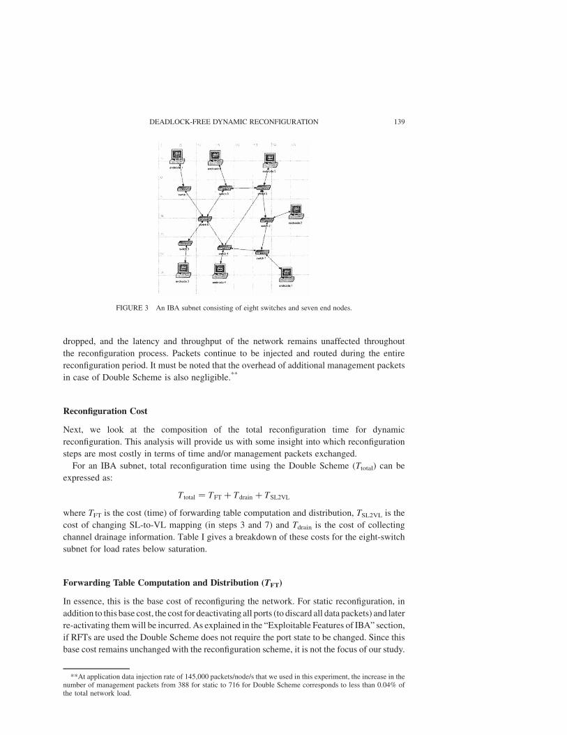
all other simulation results correspond to the IBA network shown in Fig. 3. The network
consists of eight switches and seven end nodes connected in a randomly generated topology.
Each source node generates uniform random traffic at a rate of 145,000 data packets/s which
translates roughly to 25% of saturation load rate as each packet uses a payload of 256 bytes.
Performance Comparison with Static Scheme
Figure 4 shows the IBA subnet of Fig. 3 undergoing reconfiguration triggered at simulation time
61 seconds. Both static and Double Scheme dynamic reconfiguration are shown for comparison
purposes. In the case of static reconfiguration (Fig. 4a), all network ports are brought to
INITIALIZE statek before the forwarding tables are updated. This results in the dropping of
approximately 15,000 data packets at the load rate mentioned above. Furthermore, no data
packets are injected into or delivered by the network during this period. This drop in network
throughput is highlighted in Fig. 4a. Total time taken for static reconfiguration is approximately
65 ms and the total cost, in terms of SMPs, is 388 SMPs. It is important to note that as the network
size or the applied load rate increases, the number of data packets being dropped by the static
scheme also increases.
In the case of Double Scheme dynamic reconfiguration (Fig. 4b), the total reconfiguration
time is 87.67 ms and the total number of management packets exchanged between the
network entities is 716 packets.# The important differences between the static and Double
Scheme dynamic reconfiguration results are that—for Double Scheme—no data packets are
kAccording to IBA specifications, a port in INITIALIZE state accepts management packets but not data packets.#This includes SMPs and vendor-specific GMPs used for drainage. In this section, we will use the term SMPs for
both subnet and general management packets.
B. ZAFAR et al.138
dropped, and the latency and throughput of the network remains unaffected throughout
the reconfiguration process. Packets continue to be injected and routed during the entire
reconfiguration period. It must be noted that the overhead of additional management packets
in case of Double Scheme is also negligible.**
Reconfiguration Cost
Next, we look at the composition of the total reconfiguration time for dynamic
reconfiguration. This analysis will provide us with some insight into which reconfiguration
steps are most costly in terms of time and/or management packets exchanged.
For an IBA subnet, total reconfiguration time using the Double Scheme (Ttotal) can be
expressed as:
T total ¼ TFT þ Tdrain þ TSL2VL
where TFT is the cost (time) of forwarding table computation and distribution, TSL2VL is the
cost of changing SL-to-VL mapping (in steps 3 and 7) and Tdrain is the cost of collecting
channel drainage information. Table I gives a breakdown of these costs for the eight-switch
subnet for load rates below saturation.
Forwarding Table Computation and Distribution (TFT)
In essence, this is the base cost of reconfiguring the network. For static reconfiguration, in
addition to this base cost, the cost for deactivating all ports (to discard all data packets) and later
re-activating them will be incurred. As explained in the “Exploitable Features of IBA” section,
if RFTs are used the Double Scheme does not require the port state to be changed. Since this
base cost remains unchanged with the reconfiguration scheme, it is not the focus of our study.
FIGURE 3 An IBA subnet consisting of eight switches and seven end nodes.
**At application data injection rate of 145,000 packets/node/s that we used in this experiment, the increase in thenumber of management packets from 388 for static to 716 for Double Scheme corresponds to less than 0.04% ofthe total network load.
DEADLOCK-FREE DYNAMIC RECONFIGURATION 139

Changing SL-to-VL Mapping (TSL2VL)
Unlike TFT cost, this component of the total cost is specific to Double Scheme dynamic
reconfiguration and should, therefore, be minimized in order for the scheme to be attractive.
Interestingly, the first change of SL-to-VL can happen in parallel with TFT. Therefore, the
cost of this change, in terms of time, is almost completely hidden for medium to large
networks. As a result, the network only sees the latency of TSL2VL once, i.e. in the last step of
reconfiguration. Table II clearly shows this trend. For a network, consisting of more than 16
switches, the FT computation time becomes the dominant factor.
FIGURE 4 Simulation results for (a) static and (b) Double Scheme dynamic reconfiguration for the IBA subnetshown in Fig. 3. Reconfiguration starts at time 61 s.
TABLE I Cost of various reconfiguration steps
Reconfiguration step Cast (SMPs) Cost (ms) % age of total time
FT computation 28.67 32.70%FT distribution 32 5.04 5.74%Changing SL-to-VL mapping 668 51.75 59.03%Channel drainage 16 2.21 2.52%.Total reconfiguration 716 87.67 100%
TABLE II Scaling of TFT and TSL2VL with network size
Number of switches TFT (s) TSL2VL (s) TSL2VL as % age of Ttotal
8 0.0337 0.0517 59.0312 0.1144 0.1894 62.3616 0.2143 0.1046 32.8032 1.1009 0.1998 15.3648 8.6338 0.3115, 3.4864 18.2012 0.4179 2.2496 19.3370 0.5777 2.90
B. ZAFAR et al.140
Time spent in restoring the SL-to-VL mapping (step 7) can be significantly reduced by
using LID routed SMPs instead of directed routed ones. This, however, may not be possible
in step 3 as the old routing function (which is active in step 3) may not be connected due to
the change in the network.
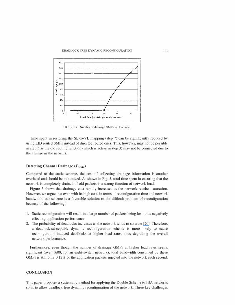
Detecting Channel Drainage (Tdrain)
Compared to the static scheme, the cost of collecting drainage information is another
overhead and should be minimized. As shown in Fig. 5, total time spent in ensuring that the
network is completely drained of old packets is a strong function of network load.
Figure 5 shows that drainage cost rapidly increases as the network reaches saturation.
However, we argue that even with its high cost, in terms of reconfiguration time and network
bandwidth, our scheme is a favorable solution to the difficult problem of reconfiguration
because of the following:
1. Static reconfiguration will result in a large number of packets being lost, thus negatively
effecting application performance.
2. The probability of deadlocks increases as the network tends to saturate [20]. Therefore,
a deadlock-susceptible dynamic reconfiguration scheme is more likely to cause
reconfiguration-induced deadlocks at higher load rates, thus degrading the overall
network performance.
Furthermore, even though the number of drainage GMPs at higher load rates seems
significant (over 1600, for an eight-switch network), total bandwidth consumed by these
GMPs is still only 0.12% of the application packets injected into the network each second.
CONCLUSION
This paper proposes a systematic method for applying the Double Scheme to IBA networks
so as to allow deadlock-free dynamic reconfiguration of the network. Three key challenges
FIGURE 5 Number of drainage GMPs vs. load rate.
DEADLOCK-FREE DYNAMIC RECONFIGURATION 141

for implementing the Double Scheme over IBA networks were identified. A number of IBA
features and mechanisms that address these challenges and how they should be used are also
described. It is shown that spatial and/or temporal separation of resources—which is the
basic idea behind the Double Scheme—can be accomplished in an IBA subnet by
distinguishing sets of SLs and destination LIDs used to route packets in the network.
Drainage of resources can be accomplished under the direction of subnet management using
various methods and attributes. An algorithm is proposed that uses mechanisms allowed by
IBA specifications to accomplish selective resource drainage. It is also shown that dynamic
update of forwarding tables and destination names is also supported by IBA in a manner
consistent with that needed for the Double Scheme. Finally, simulations results presented in
this paper show that the cost of implementing the Double Scheme on IBA, in terms of
reconfiguration time and additional management packets, justify the performance benefits
achieved. As a result, this work enables InfiniBand networks to better support applications
requiring certain QoS guarantees that would not well tolerate intermittent performance
drops-offs, as would be the case without deadlock-free dynamic reconfigurabilty. Interesting
future work could focus on optimizing various reconfiguration steps, such as developing
more efficient drainage schemes based on exponential back-off rather than periodic polling.
Acknowledgements
We acknowledge the efforts of Rafael Casado and Francisco J. Quiles in helping to provide
support for IBA modeling and simulation on OPNETe, and we are grateful to OPNET for
use of their OPNET Modeler simulation tool. This research is supported partly by NSF grant
CCR-0209234 and Spanish CICYT grant TIC2003-08154-C6.
References
[1] Pang, Ruoming, Pinkston, Timothy Mark and Duato, Jose (2000) “The Double Scheme: deadlock-free dynamicreconfiguration of cut-through networks”, The 2000 International Conference on Parallel Processing (IEEEComputer Society), August, pp 439–448.
[2] Buyya, R. (1999) High Performance Cluster Computing (Prentice-Hall, New York).[3] Gregory F. Pfister (2000) “An introduction to the infiniband architecture”, In Proceedings of the Cluster
Computing Conference (Cluster00) Chapter 57, November 2000.[4] Charles Spurgeon (1995) Quick Reference Guide to the Ethernet System. http://wwwhost:ots.utexas.edu/
ethernet/descript-100quickref.html.[5] Schroeder, M.D., Birrell, A.D., Burrows, M., Murray, H., Needham, R.M., Rodeheffer, T.L., Satterthwaite, E.H.
and Thacker, C.P. (1991) “Autonet: a high-speed self-configuring local area network using point-to-pointlinks”, IEEE Journal on Selected Areas in Communication 9(8), 1318–1335, October.
[6] Felderman, R.E., Kulawik, A.E., Seitz, C.L., Seizovic, J., Boden, N.J., Cohen, D. and Su, W. (1995) “Myrinet—a gigabit per second local area network”, IEEE Micro, 29–36, February.
[7] Kumar Malavalli et al. (2000) Fibre Channel Switch Fabric-2 (FC-SW-2). NCITS 321-200x T11/Project1305-D/Rev 4.3 Specification, pp. 57–74.
[8] InfiniBande Architecture Specification Volume 1, Release 1.0. InfiniBand Trade Association, October 24,2000.
[9] Duato, J. (1993) “A new theory of deadlock-free adaptive routing in wormhole networks”, IEEE Transactionson Parallel and Distributed Systems 4(12), 1320–1331.
[10] Duato, J. (1995) “A necessary and sufficient condition for deadlock-free adaptive routing in wormholenetworks”, IEEE Transactions on Parallel and Distributed Systems 6(10), 1055–1067.
[11] Sancho, Jose Carlos, Robles, Antonio and Duato, Jose (2001) “Effective strategy to compute forwarding tablesfor infiniband networks”, Proceedings of the International Conference on Parallel Processing (IEEE ComputerSociety Press, Los Alamitos CA), September, pp 48–57.
[12] Lopez, Pedro, Flich, Jose and Duato, Jose (2001) “Deadlock-free routing in Infiniband through destinationrenaming”, Proceedings of the International Conference on Parallel Processing (IEEE Computer Society Press,Los Alamitos CA), September, pp 427–434.
B. ZAFAR et al.142

[13] Aurelio Bermudez, Rafael Casado, Quiles, F.J., Timothy M. Pinkston and Jose Duato (2003) Evaluation of asubnet management mechanism for infiniband networks. In International Conference on Parallel Processing,October.
[14] Avresky, Dimiter (2000) Dependable Network Computing (Kluwer Academic Publishers, Dordrecht),Chapter 10.
[15] Casado, R., Bermudez, A., Quiles, F.J., Sanchez, J.L. and Duato, Jose (2001) “A protocol for deadlock-freedynamic reconfiguration in high-speed local area networks. Special Issue on Dependable NetworkComputing”, IEEE Transactions on Parallel and Distributed Systems 12(2), 115–132.
[16] Aurelio Bermudez, Rafael Casado, Quiles, F.J., Timothy M. Pinkston and Jose Duato (2003) “Modelinginfiniband with opnet”, In 2nd Annual Workshop on Novel Uses of System Area Networks.
[17] Dally, W. and Seitz, C. (1987) “Deadlock-free Message Routing in Multiprocessor Interconnection Networks”,IEEE Transactions on Computers 36(5), 547–553.
[18] Duato, J., Yalamanchili, S. and Ni, L. (1997) Interconnection Networks: An Engineering Approach (IEEEComputer Society Press, Los Alamitos CA).
[19] OPNET Technologies Inc. http://www.opnet.com.[20] Warnakulasuriya, Sugath (1999) Characterization of Deadlocks in Interconnection Networks, Ph.D. thesis
(University of Southern California).
DEADLOCK-FREE DYNAMIC RECONFIGURATION 143