Models and Verification for Composition and Reconfiguration ...
144
HAL Id: tel-03188299 https://tel.archives-ouvertes.fr/tel-03188299 Submitted on 1 Apr 2021 HAL is a multi-disciplinary open access archive for the deposit and dissemination of sci- entific research documents, whether they are pub- lished or not. The documents may come from teaching and research institutions in France or abroad, or from public or private research centers. L’archive ouverte pluridisciplinaire HAL, est destinée au dépôt et à la diffusion de documents scientifiques de niveau recherche, publiés ou non, émanant des établissements d’enseignement et de recherche français ou étrangers, des laboratoires publics ou privés. Models and Verification for Composition and Reconfiguration of Web of Things Applications Ajay Krishna Muroor Nadumane To cite this version: Ajay Krishna Muroor Nadumane. Models and Verification for Composition and Reconfiguration of Web of Things Applications. Other [cs.OH]. Université Grenoble Alpes [2020-..], 2020. English. NNT : 2020GRALM067. tel-03188299
-
Upload
khangminh22 -
Category
Documents
-
view
0 -
download
0
Transcript of Models and Verification for Composition and Reconfiguration ...

HAL Id: tel-03188299https://tel.archives-ouvertes.fr/tel-03188299
Submitted on 1 Apr 2021
HAL is a multi-disciplinary open accessarchive for the deposit and dissemination of sci-entific research documents, whether they are pub-lished or not. The documents may come fromteaching and research institutions in France orabroad, or from public or private research centers.
L’archive ouverte pluridisciplinaire HAL, estdestinée au dépôt et à la diffusion de documentsscientifiques de niveau recherche, publiés ou non,émanant des établissements d’enseignement et derecherche français ou étrangers, des laboratoirespublics ou privés.
Models and Verification for Composition andReconfiguration of Web of Things Applications
Ajay Krishna Muroor Nadumane
To cite this version:Ajay Krishna Muroor Nadumane. Models and Verification for Composition and Reconfiguration ofWeb of Things Applications. Other [cs.OH]. Université Grenoble Alpes [2020-..], 2020. English. �NNT :2020GRALM067�. �tel-03188299�

THÈSE
Pour obtenir le grade de
DOCTEUR DE L’UNIVERSITE GRENOBLE ALPES
Spécialité : Informatique
Arrêté ministériel : 25 mai 2016
Présentée par
Ajay Krishna MUROOR NADUMANE Thèse dirigée par Gwen SALAÜN, Professeur, Université Grenoble Alpes, et Co-encadrée par Radu MATEESCU, Directeur de recherche, Inria
Grenoble - Rhône-Alpes, et Michel LE PALLEC, Ingénieur de recherche, Nokia Bell Labs France préparée au sein du CONVECS Inria Grenoble - Rhône-Alpes dans l'École Doctorale Mathématiques, Sciences et technologies de l'information, Informatique Models and Verification for Composition and Reconfiguration of Web of Things Applications Modèles et vérification pour la composition et la reconfiguration d'applications basées sur le web des objets
Thèse soutenue publiquement le 10 déc. 2020, devant le jury composé de :
Monsieur Olivier BARAIS Professeur, Université de Rennes 1, Examinateur
Monsieur Didier DONSEZ Professeur, Université Grenoble Alpes, Président
Madame Pascale LE GALL Professeur, CentraleSupélec, Rapporteur
Monsieur Michel LE PALLEC Ingénieur de recherche, Nokia Bell Labs, Co-encadrant de thèse
Monsieur Radu MATEESCU Directeur de recherche, Inria Grenoble, Co-encadrant de thèse
Monsieur Juan Manuel MURILLO RODRIGUEZ Professeur, Universidad de Extremadura, Rapporteur
Monsieur Gwen SALAÜN Professeur, Université Grenoble Alpes, Directeur de thèse
Monsieur Farouk TOUMANI Professeur, Université Clermont Auvergne, Examinateur


Abstract
The Internet of Things (IoT) applications are built by interconnecting everydayobjects over a network. These objects or devices sense the environment aroundthem, and their network capabilities allow them to communicate with other objectsto perform utilitarian tasks. One of the popular ways to build IoT applications in theconsumer domain is by combining different objects using Event-Condition-Action(ECA) rules. These rules are typically in the form of IF something-happens THENdo-something. The Web of Things (WoT) are a set of standards and principles thatintegrate architectural styles and capabilities of web to the IoT. Even though WoTarchitecture coupled with ECA rules simplifies the building of IoT applications to alarge extent, there are still challenges in making end-users develop advanced appli-cations in a simple yet correct fashion due to dynamic, reactive and heterogeneousnature of IoT systems. The broad objective of this work is to leverage formal methodsto provide end-users of IoT applications certain level of guarantee at design time thatthe designed application will behave as intended upon deployment. In this context,we propose a formal development framework based on the WoT. The objects are de-scribed using a behavioural model derived from the Thing Description specificationof WoT. Then, the applications are designed not only by specifying individual ECArules, but also by composing these rules using a composition language. The languageenables users to build more expressive automation scenarios. The description of theobjects and their composition are encoded in a formal specification from which thecomplete behaviour of the application is identified. In order to guarantee correctdesign of the application, this work proposes a set of generic and application-specificproperties that can be validated on the complete behaviour before deployment.Further, the deployed applications may be reconfigured during their applicationlifecycle. The work supports reconfiguration by specifying reconfiguration propertiesthat allow one to qualitatively compare the behaviour of the new configuration withthe original configuration. The implementation of all the proposals is achieved byextending the Mozilla WebThings platform. A new set of user interfaces have beenbuilt to support the composition of rules and reconfiguration. A model transforma-tion component which transforms WoT models to formal models and an integrationwith formal verification toolbox are implemented to enable automation. Finally, adeployment engine is built by extending WebThings APIs. It directs the deploymentof applications and reconfigurations respecting their composition semantics.
iii

RésuméLes applications de l’Internet des objets (IoT) sont construites en interconnectantles objets du quotidien en réseau. Les objets connectés collaborent ensemble, afind’observer l’environnement les entourant, et agir sur celui-ci. Pour le grand pub-lic, l’un des moyens de créer des applications IoT consiste à combiner différentsobjets à l’aide de règles d’action conditionnelle (ECA). Ces règles se présententgénéralement sous la forme « SI quelque chose se produit, ALORS faire quelquechose ». Le web des objets (Web of Things ou WoT) est un ensemble de normeset de principes qui intègrent les capacités du web et les styles architecturaux àl’IoT. Bien que l’architecture WoT associée aux règles de la ECA simplifie dans unelarge mesure la construction d’applications IoT, il reste des défis à relever afin queles utilisateurs finaux puissent développer aisément des applications avancées etcorrectes, en raison de la nature dynamique, réactive et hétérogène des systèmesIoT. L’objectif général de ce travail est de tirer parti des méthodes formelles pourfournir un certain niveau de garantie aux utilisateurs finaux des applications IoT.Cela permet, au moment de la conception, d’assurer que l’application conçue secomportera comme prévu lorsque celle-ci sera déployée. Dans ce contexte, nousproposons un cadre de développement formel basé sur le WoT. Les objets sont décritsà l’aide d’un modèle dérivé de la spécification Thing Description du WoT. Ensuite, lesapplications sont conçues non seulement en spécifiant les règles individuelles ECA,mais aussi en associant ces règles à l’aide d’un langage de composition. Ce langagepermet aux utilisateurs de construire des scénarios d’automatisation plus expressifs.La description des objets et leur composition sont traduites dans une spécificationformelle à partir de laquelle le comportement complet de l’application est identifié.Afin de garantir une conception correcte de l’application avant le déploiement, cettethèse propose de valider un ensemble de propriétés génériques et spécifiques sur lecomportement complet de l’application. En outre, les applications déployées peuventêtre reconfigurées au cours de leur cycle de vie. Le travail supporte la reconfigu-ration en spécifiant des propriétés de reconfiguration qui permettent de comparerqualitativement le comportement de la nouvelle configuration avec la configurationd’origine. La mise en œuvre de toutes les propositions est réalisée en étendant laplate-forme Mozilla WebThings. Un nouvel ensemble d’interfaces utilisateur estconstruit pour prendre en charge la composition des règles et la reconfigurationde l’application. Un composant permettant de transformer automatiquement lesmodèles WoT en modèles formels, pleinement intégré au sein d’une boite à outils devérification formelle a été développé. Enfin, un moteur de déploiement est construiten étendant les API de WebThings. Il dirige le déploiement des applications et desreconfigurations en respectant la sémantique de leur composition.
iv

Acknowledgement
I would like to express my sincerest gratitude to all the people who have contributedto wonderful learning experience during the last three years.
First and foremost, I must thank my thesis director Prof. Gwen Salaün, without hisguidance and supervision, the work would not have materialised. Prof. Salaün’sexperience, knowledge and passion for work has positively influenced my work.He was always willing to listen, understand the problem and guide me in the rightdirection. My heartfelt thanks to Prof. Radu Mateescu for his gentle and timelyguidance which helped me resolve some of the most challenging problems of mywork. I have immensely benefited from his wealth of experience which I will carryinto rest of my work and life. My thanks to Dr. Michel Le Pallec for bringing anindustrial perspective to my work. He was a perfect host whenever I visited BellLabs, Paris.
I am also grateful to be working with highly talented people, who are among thebest in what they do, as part of Convecs team at Inria. Prof. Hubert Garavel, wasalways there to help whenever I needed his advice. My thanks to Prof. FredericLang for his help on technical matters and also enriching discussions over lunch.I would like to thank Prof. Wendelin Serwe for his help especially related to LNTand modelling. I am thankful to Ms. Myriam Etienne for helping me in managingthe administrative aspects of the PhD. My special thanks to all the non-permanentmembers of the team (PhD students, researchers, interns). I am grateful for theirhelp not just in technical matters, but also in day-to-day life. They made my staypleasant and fun. I consider myself lucky to be a part of this team where everyonewas willing to take time out to help me whenever I popped up with questions.
Thanks to members of IoT Control Group at Bell Labs, Paris for their collaboration.
I must thank the reviewers of my thesis and the examiners for reviewing my workand participating in my thesis defense in a period like no other.
A big thanks to my friends and family, who have been a pillar of support and helpedme to pursue my goals.
v


Contents
1 Introduction 1
1.1 Context and Motivation . . . . . . . . . . . . . . . . . . . . . . . . . 3
1.2 Approach . . . . . . . . . . . . . . . . . . . . . . . . . . . . . . . . . 8
1.3 Contributions . . . . . . . . . . . . . . . . . . . . . . . . . . . . . . . 10
1.4 Chronology of Work . . . . . . . . . . . . . . . . . . . . . . . . . . . 12
1.5 Thesis Structure . . . . . . . . . . . . . . . . . . . . . . . . . . . . . . 13
2 Related Work 15
2.1 IoT Application Models . . . . . . . . . . . . . . . . . . . . . . . . . . 15
2.2 Expressiveness of ECA Languages . . . . . . . . . . . . . . . . . . . . 19
2.3 Verification of IoT Applications . . . . . . . . . . . . . . . . . . . . . 20
2.4 Reconfiguration of IoT Applications . . . . . . . . . . . . . . . . . . . 23
2.5 End-User Tools in Smart Homes . . . . . . . . . . . . . . . . . . . . . 25
2.6 Concluding Remarks . . . . . . . . . . . . . . . . . . . . . . . . . . . 30
3 Background 31
3.1 Behavioural Models . . . . . . . . . . . . . . . . . . . . . . . . . . . . 31
3.2 LNT Language . . . . . . . . . . . . . . . . . . . . . . . . . . . . . . . 33
3.3 Model Checking . . . . . . . . . . . . . . . . . . . . . . . . . . . . . . 39
3.4 Rewriting Logic . . . . . . . . . . . . . . . . . . . . . . . . . . . . . . 42
4 A Formal Model for the Web of Things 45
4.1 Web of Things Specification . . . . . . . . . . . . . . . . . . . . . . . 46
4.2 Model for IoT Objects . . . . . . . . . . . . . . . . . . . . . . . . . . 50
4.3 ECA Rules and a Language for Composition . . . . . . . . . . . . . . 53
4.4 Specification in LNT . . . . . . . . . . . . . . . . . . . . . . . . . . . 63
4.5 Specification in Maude . . . . . . . . . . . . . . . . . . . . . . . . . . 71
4.6 Concluding Remarks . . . . . . . . . . . . . . . . . . . . . . . . . . . 74
5 Property Specification for the Web of Things 75
5.1 Design-time Verification with MCL . . . . . . . . . . . . . . . . . . . 75
5.1.1 Generic Properties . . . . . . . . . . . . . . . . . . . . . . . . 76
vii

5.1.2 Application Properties . . . . . . . . . . . . . . . . . . . . . . 815.2 Reconfiguration Properties . . . . . . . . . . . . . . . . . . . . . . . . 84
5.2.1 Seamless Reconfiguration . . . . . . . . . . . . . . . . . . . . 845.2.2 Conservative Reconfiguration . . . . . . . . . . . . . . . . . . 875.2.3 Impactful Reconfiguration . . . . . . . . . . . . . . . . . . . . 895.2.4 Reconfiguration Example . . . . . . . . . . . . . . . . . . . . 91
5.3 Concluding Remarks . . . . . . . . . . . . . . . . . . . . . . . . . . . 92
6 Mozart Tool 936.1 Project WebThings . . . . . . . . . . . . . . . . . . . . . . . . . . . . 93
6.1.1 WebThings Gateway . . . . . . . . . . . . . . . . . . . . . . . 936.2 WebThings Extensions for Design-time Verification and Reconfiguration 96
6.2.1 Design-time Verification Components . . . . . . . . . . . . . . 976.2.2 Reconfiguration Components . . . . . . . . . . . . . . . . . . 99
6.3 Technology and Implementation . . . . . . . . . . . . . . . . . . . . . 1016.3.1 CADP Toolbox . . . . . . . . . . . . . . . . . . . . . . . . . . . 1016.3.2 Maude System . . . . . . . . . . . . . . . . . . . . . . . . . . 1036.3.3 Implementation . . . . . . . . . . . . . . . . . . . . . . . . . . 103
6.4 Evaluation . . . . . . . . . . . . . . . . . . . . . . . . . . . . . . . . . 1046.4.1 Expressiveness of Compositions . . . . . . . . . . . . . . . . . 1046.4.2 User Feedback . . . . . . . . . . . . . . . . . . . . . . . . . . 1066.4.3 Verification Performance . . . . . . . . . . . . . . . . . . . . . 1086.4.4 Deployment Setup . . . . . . . . . . . . . . . . . . . . . . . . 110
6.5 Discussion . . . . . . . . . . . . . . . . . . . . . . . . . . . . . . . . . 112
7 Conclusion 1137.1 Models for the IoT . . . . . . . . . . . . . . . . . . . . . . . . . . . . 1137.2 Verification for the IoT . . . . . . . . . . . . . . . . . . . . . . . . . . 1147.3 Tool Implementation . . . . . . . . . . . . . . . . . . . . . . . . . . . 1157.4 Future Work . . . . . . . . . . . . . . . . . . . . . . . . . . . . . . . . 116
Bibliography 119
viii

Introduction 1„As machines become more and more efficient and
perfect, so it will become clear that imperfectionis the greatness of man.
— Ernst FischerAustrian journalist, writer and politician
Over the years, communication technologies and electronics have evolved rapidly,and this has brought the world closer than ever. Among them, the internet hashelped uncover new frontiers beyond traditional communication. The internet, intandem with modern electronic devices, has shattered geographical and culturalbarriers, created communities of unimaginable scale and reach, enabled a new breedof enterprises. The Internet of Things (IoT) is one such possibility unleashed by theadvent of network communication and modern electronics. In a broad sense, IoTencompasses everything in the physical world that is connected to the internet andwe refer this ‘everything’ as objects or devices. An object could be as simple as a lightbulb that we use every day, or it could be a complex industrial controller connected tothe internet. These objects can communicate with each other and perform utilitariantasks. The International Telecommunication Union (ITU) defines IoT as: “A globalinfrastructure for the information society, enabling advanced services by interconnecting(physical and virtual) things based on existing and evolving interoperable informationand communication technologies” [ITU16]. In this work, we call IoT applications a setof interconnected things designed to serve a specific purpose.
Kevin Ashton, a technologist, first introduced the term IoT in the year 1999 during apresentation at Procter & Gamble (P&G) to describe internet connected systems thatinteract with physical world through ubiquitous sensors [LLC13]. This definitionstemmed out of his research on internet connected Radio-frequency Identification(RFID). However, the idea of connected objects that capture their surroundings isnot new and it goes back even further than the advent of the internet. The PlainOld Telephony System (POTS) developed in the late 18th century can be consideredas the first connected object system. It captured the sound as an analog signal andtransmitted it using conductive wires. Later with the invention of radio, wireless
1
communication systems came into the market and they enabled a new generation ofconnected systems. A significant breakthrough in 1959 led to the birth of modernelectronics: researchers at Bell Labs invented Metal–Oxide–Semiconductor Field-Effect Transistor (MOSFET), a semiconductor device widely used in digital andanalog integrated circuits [Mus20].
If we want to look at an early instance of a more pertinent IoT application, it is theconnected soda vending machine at Carnegie Mellon University (CMU). Researchersin the 1980s implemented an application to check if the soda vending machine wasempty or recently restocked (the drinks would be warm if they were recently placedinside the machine) from the comfort of their offices [Uni70]. It was achieved usinga circuit board connected to the ARPANET, the predecessor of the internet. It isworth noting that the concept of connected objects is not limited to the consumerdomain. In 1995, Siemens introduced the M1 GSM module, which pioneeredcellular machine-to-machine (M2M) communication [Bha18]. It further ushered anew era of industrial manufacturing with remote monitoring, control, and telemetryinvolving embedded control systems. As time passed, machines have evolved notonly to understand the world around themselves but also to coordinate with othermachines and take meaningful decisions.
The IoT ecosystem is rapidly growing towards playing a central role in many ap-plication areas like healthcare, transportation, agriculture, manufacturing, smarthomes, and smart cities. It is expected that nearly 125 billion connected IoT devicesare to be deployed by 2030 [MTK18]. This explosive growth can be explained byunderstanding how IoT delivers value to our daily lives.
Simple sensors like a Bluetooth transceiver or a temperature sensor may seem onlyof specific use when viewed in isolation. The transceiver can exchange data withnearby objects and the temperature sensor can measure the body temperature.But when we connect these seemingly simple objects to the internet and enablethem to communicate with each other, the possibilities are beyond the obvious. Forinstance, Bluetooth combined with GPS helped in contact tracing during the recentCoronavirus outbreak [Gre20]. Smart 1 thermometers played a key role in trackingand reducing the spread of Coronavirus by aggregating the temperature data ofconsumers and accurately predicting the spread of virus even before symptomsappeared in patients [YS20].
1prefixing smart to everyday objects is a way to convey the readers that the object has network andprogramming capabilities
2 Chapter 1 Introduction

1.1 Context and Motivation
As with every system that marches towards maturity, there are some growing painsthat need to be overcome before the successful adoption of IoT ecosystem. We aimto solve the challenges in the IoT ecosystem through the usage of formal methods.Before we present the challenges in detail, let us take a quick look at the techniquesassociated with formal methods. It is important to introduce these techniques as tounderstand how they can fit in to tackle the challenges in the IoT domain.
Formal Specification and Verification Techniques
Formal methods are techniques grounded on mathematics and formal logic. Usingthese techniques, complex software, hardware, and cyberphysical systems can bemodelled as mathematical entities. The process of describing a non-mathematicalrepresentation of a system in a precise formal language is known as formal speci-fication. The rigorous syntax and semantics of the formal language enable formaldeduction about the specification. Since the specification captures the behaviour ofthe system with precision and unambiguity, it can be used to mathematically verifythe implementation.
Model checking [BPS01] is a formal verification technique where a system is mod-elled in terms of a finite state machine. This model is fed to a model checker whichdetermines if the given model satisfies properties expressed as logical formulas.Equivalence checking [CS01] is another verification technique which determineswhether two models are functionally or semantically equivalent.
Term rewriting [BN99] is a computational technique that deals with equationscalled rewrite rules. It is a reduction process where rewrite rules are applied toterms. A term could be a variable, constant or a result of an operation on variablesand constants. Rewriting logic theory models the static and dynamic aspects ofa concurrent system. It consists of an equational theory and a set of conditionalrewrite rules representing the static and dynamic aspects [Mes12], respectively.Equational theory combined with the rewrite rules can specify how a concurrentsystem evolves with respect to its states.
The verification techniques mentioned above can be applied to IoT applications tovalidate that they behave as intended. Validation of IoT applications is important asthere are certain characteristics intrinsic to the applications which make it difficult
1.1 Context and Motivation 3
to guarantee their correct behaviour. In the subsequent text, we describe thesecharacteristics and how formal methods can be placed in this context.
IoT Application Characteristics and Formal Methods
Among the various characteristics of concurrent systems, the ones that make thedevelopment of IoT applications a challenge can be broadly described under threecategories.
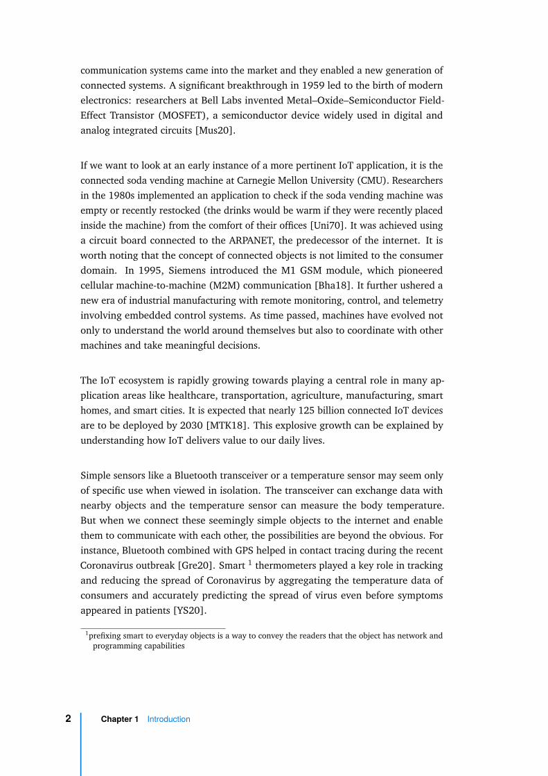
Heterogeneity: As the IoT ecosystem evolved, it leveraged various underlyingtechnologies, standards, and protocols. There are various standards at differentlevels of IoT stack [Fuq+15].
Fig. 1.1: IoT standards and protocols
Figure 1.1 provides a snapshot of existing standards in IoT across different layers ofthe network stack. The list of standards mentioned in Figure 1.1 is not exhaustive,but it tries to give an idea of the diversity present across different layers of the system.The reasons for this diversity are many: evolution of standards over time, proprietarystandards, large number of small manufacturers who have constraints to implementstandards etc. As Petrarch would say, variety is the cure; these standards provide
4 Chapter 1 Introduction

ample choice for developing IoT systems but, they bring in a baggage of interoper-ability issues. To build a truly global infrastructure for the information society asenvisaged by ITU-T, having a single standard would be ideal. So efforts are focussedon building multi-layer frameworks sometimes reusing these protocols, to overcomefragmentation and allow systems with different underlying standards to be inter-operable. There are various organizations and alliances working on this initiative.Internet Engineering Task Force (IETF) has proposed CoRE (Constrained RESTfulEnvironments), OneM2M [Par20] is a Machine2Machine (M2M) standard for IoT,and Weave is an application level protocol backed by Google. Last but not least,the World Wide Web Consortium (W3C) has published Web of Things [W3C20c], aspecification based on the principles of web [GT09].
Although these frameworks solve the problem of interoperability to a large extent,the underlying heterogeneity still remains and thus the difficulties in understandingthe complete behaviour of the system. Formal specification of the behaviour can beof help in this area as one can define the behaviour of the different heterogeneoussystems in a uniform and unambiguous manner. This specification can provide aplatform agnostic definition of the system.
Complexity and dynamicity: The heterogeneity of IoT systems makes it complexto deploy and manage them. Along with this, another salient feature of an IoTsystem which adds to the complexity is its distributed architecture. IoT systems arebuilt to be distributed, spread across network and geographical boundaries. IoTsystems range from small home applications to large deployments like smart cities,manufacturing, etc., and a distributed architecture is readily scalable. However, asdistributed systems exhibit a high level of concurrency, it can be a challenge to assesthe consistency and correctness of these systems, especially when their behavioursare not clearly defined [Alu+16].
IoT objects being reactive systems, constantly interact with their environment andthus change their states. This behaviour of objects makes the IoT application highlydynamic and thus, susceptible to unexpected behaviour. Identifying unexpectedbehaviour and at the same time ensuring that required behaviour is in place can bea challenge, even more so in a dynamic system.
By specifying the unexpected and intended behaviours in a system as properties, onecan check using model checking techniques whether these properties hold on theformal specification of the system. The property specification and verification canhelp detect errors in a dynamic and distributed system, which in effect allows one toobtain correctness guarantees with respect to the behaviour of the system.
1.1 Context and Motivation 5
Maintenance and evolution of applications: IoT applications, especially in theconsumer domain are not built once for all. They are being constantly modified orupgraded just like any other consumer electronic device these days. Compared totraditionally stable applications like manufacturing lines, enterprise software, etc.,the IoT applications evolve at a faster rate. For example, the change in an application(reconfiguration) could be due to a replacement when a device goes out of serviceor it could be an upgrade of the device software (functionality). In some cases anapplication could be entirely replaced to provide altogether a new service.
Evolution of an application involves replacement of an existing behaviour by a newbehaviour. Under typical circumstances, the application behaviour is not completelyreplaced but rather users would like to partially preserve or extend the existingbehaviour. One of the challenges in reconfiguration is to qualitatively measure theimpact of the change with respect to the existing configuration. Additionally, thereconfiguration takes place during the execution lifecycle of the application andtherefore, the impact to running applications should be kept minimal in order topreserve the functionality and quality of service as much as possible.
Term rewriting can efficiently track the evolution of the states in a system as rewritingis primarily a replacement of an expression representing the state of the object byan equivalent expression. Rewriting analysis can identify whether the states in asystem are equivalent and also determine whether the two different systems leadto the same state (converge). These techniques can be used in the context of IoTapplications in two areas: first, to track the evolution of the system with respect tothe original system; and second, to identify the ways to evolve from the originalsystem to the desired system maintaining the consistency of states.
Automation in Smart Homes
The problems mentioned in the earlier section require a range of solutions, some ofwhich are beyond the scope of this work. Furthermore, even though these problemsappear across various IoT domains, the solutions would be more meaningful ifthey are domain specific. So, we focussed our work on consumer IoT, specificallyapplying our approach on smart homes. Smart home automation is one of the fastestgrowing areas in IoT. Users can automate tasks in their homes using the smartobjects available in the market and unlike industrial automation tasks, this is notlimited to skilled or expert users. Usability is a key factor in any system to gain wideadoption, especially where end-users are consumers. In a survey of 250 participantsat the 2017 Consumer Electronics Show (CES), almost all (>99%) participants
6 Chapter 1 Introduction
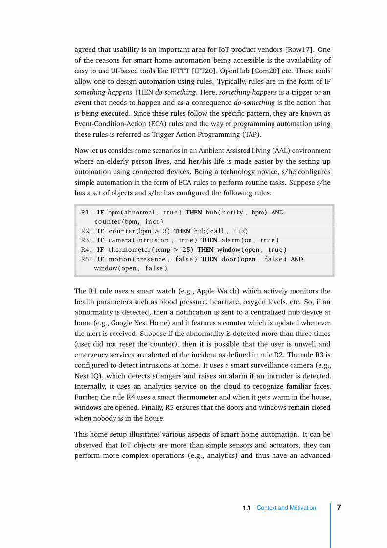
agreed that usability is an important area for IoT product vendors [Row17]. Oneof the reasons for smart home automation being accessible is the availability ofeasy to use UI-based tools like IFTTT [IFT20], OpenHab [Com20] etc. These toolsallow one to design automation using rules. Typically, rules are in the form of IFsomething-happens THEN do-something. Here, something-happens is a trigger or anevent that needs to happen and as a consequence do-something is the action thatis being executed. Since these rules follow the specific pattern, they are known asEvent-Condition-Action (ECA) rules and the way of programming automation usingthese rules is referred as Trigger Action Programming (TAP).
Now let us consider some scenarios in an Ambient Assisted Living (AAL) environmentwhere an elderly person lives, and her/his life is made easier by the setting upautomation using connected devices. Being a technology novice, s/he configuressimple automation in the form of ECA rules to perform routine tasks. Suppose s/hehas a set of objects and s/he has configured the following rules:
R1 : IF bpm( abnormal , t rue ) THEN hub( no t i f y , bpm) ANDcounter (bpm, i n c r )
R2 : IF counter (bpm > 3) THEN hub( c a l l , 112)R3 : IF camera ( in t ru s i on , t rue ) THEN alarm (on , t rue )R4 : IF thermometer ( temp > 25) THEN window(open , t rue )R5 : IF motion ( presence , f a l s e ) THEN door (open , f a l s e ) AND
window(open , f a l s e )
The R1 rule uses a smart watch (e.g., Apple Watch) which actively monitors thehealth parameters such as blood pressure, heartrate, oxygen levels, etc. So, if anabnormality is detected, then a notification is sent to a centralized hub device athome (e.g., Google Nest Home) and it features a counter which is updated wheneverthe alert is received. Suppose if the abnormality is detected more than three times(user did not reset the counter), then it is possible that the user is unwell andemergency services are alerted of the incident as defined in rule R2. The rule R3 isconfigured to detect intrusions at home. It uses a smart surveillance camera (e.g.,Nest IQ), which detects strangers and raises an alarm if an intruder is detected.Internally, it uses an analytics service on the cloud to recognize familiar faces.Further, the rule R4 uses a smart thermometer and when it gets warm in the house,windows are opened. Finally, R5 ensures that the doors and windows remain closedwhen nobody is in the house.
This home setup illustrates various aspects of smart home automation. It can beobserved that IoT objects are more than simple sensors and actuators, they canperform more complex operations (e.g., analytics) and thus have an advanced
1.1 Context and Motivation 7

behaviour (e.g., the hub and surveillance camera). It is important to consider thebehaviour of the objects while designing the rules. For instance, in case of R3, theintrusion detection feature is dependent on the cloud service and this information isnot captured in the automation rules. Further in R1, if the user replaces his watchby another watch of a different make, which does not have an arrythmia detectionfeature, then this abnormality will not be captured by the rule. It can have seriousconsequences on the health of the user. This problem arises because there are nomechanisms to check if the automations are functionally equivalent. In most of theautomation setups, the rules are run in parallel (whenever the events occur). Nowconsidering the rules R4 and R5, there is no guarantee that the windows are alwaysclosed when nobody is in the house (temperature can be > 25). This is can be asecurity issue as the windows might open when the user is away from the home.There are no checks at design time that help users detect unsafe automation.
Considering these aspects, our goal is to enable users design applications in asimple manner, yet provide them with means to ensure that the applications behaveas intended upon deployment. This correctness guarantee is accomplished byconsidering not only the rules but also the behaviour of the individual objects.
1.2 Approach
As mentioned earlier, our work leverages formal methods to address the challengespresented in Section 1.1. Formal modelling allows to specify the behaviour of IoTapplications in an abstract manner, independent of the underlying heterogeneouscomponents. This specification can be analysed using formal verification techniquesto ensure that the system behaves as intended, i.e., it satisfies certain properties ofinterest. The specification of an application encompasses objects, rules, and theirinteractions with the physical environment.
We specify the application on the basis of a multi-layer framework, as these frame-works provide horizontal integration which bridges different protocols. Thus, itallows us to focus on specifying the application behaviour without worrying aboutunderlying protocols. It also makes our approach applicable to all the real-worldobjects and applications which are supported by the framework. The Web of Things(WoT) is a framework that helps to mitigate the interoperability issues by abstractingthe underlying details, yet providing necessary interfaces for the users to developIoT applications. It uses architectural styles and principles of the web, where eachobject is identified by its URI. The object’s capabilities and the ways to interact
8 Chapter 1 Introduction

with it, are specified by a machine-readable description called Thing Description(TD) [W3C20b].
As a first step, we specify the behaviour of an object on the basis of its TD. Thebehaviour is described in terms of a Labelled Transition System (LTS), a state-transition graph where the system moves from one state to another state dependingon the action performed either by the system itself or an external environment.These objects can be used in defining the automation rules. Rules are in the form ofIF something-happens THEN do-something. Further, we use a language for composingthese rules, which allows one to define more advanced applications in comparison torunning the rules independently. Finally, the execution of the application is capturedby specifying an environment which interacts with the objects and thus affects therules and their composition.
Once the model of the application is available, we identified a set of propertiesthat can be checked on the model. These properties are specified as temporallogic formulas. If a model fails to satisfy any of these properties, it indicates thatthe application behaviour may not be as expected and therefore the design of theapplication needs to be revised. Once the design is satisfactory, one can proceed todeploy the application.
Regarding the implementation, the application is formally specified in LNT [Cha+18;GLS17], a language with process algebra semantics and programming languagesyntax. LNT models can be compiled and analysed in CADP [Gar+13], a formalverification toolbox. The correctness properties are specified using Model CheckingLanguage (MCL) [MT08], a data-handling temporal logic suitable for expressingproperties of value-passing concurrent systems. The compilers of CADP translate LNTspecifications to LTSs on which the MCL formulas are checked and correspondingdiagnostics are produced on the fly.
Further, to support possible evolutions of the application over time, we identifyreconfiguration properties allowing the designer to compare the current applica-tion with a new one. The properties check whether it is possible to deploy theapplication maintaining the consistency of states of objects, if the behaviour of thecurrent application is preserved in the new application, and the impact of the newapplication. This check is achieved by specifying the composition and properties inMaude rewriting logic [Cla+07] as it allows us to track the evolution of the states ofobjects in the application through rewrite equations.
Users of IoT objects need to be aware of their capabilities and they should be easilyable to exploit these capabilities to build useful applications. In the consumer domain,
1.2 Approach 9

there are broadly two ways in which users can build applications. First, users withprogramming knowledge can take advantage of the device and platform APIs likeAndroid Things to build applications. Users who lack programming experience orthose who prefer not to use it, can build IoT applications using UI-based tools such asIFTTT [IFT20] and Node-RED [Fou20]. These tools abstract the programming APIsand present users with simple drag-and-drop interfaces to build applications. On thesurface it seems that this approach is working well as there is significant adoptionof these tools from the general public, but if we dig deeper we find two issues: i)users face difficulties in translating the applications they have in mind into the UItools [Bri+17]. This is partly due to the fact that these tools are not sufficientlyexpressive to capture the user requirements [Ur+14; HC15]; and ii) even if theusers could design intended applications, they face difficulties in understanding thecomplete behaviour of the designed application [Bri+17] and if the behaviour is notfully understood, there is no guarantee that the system works as intended.
Keeping these usability issues in mind, we built a tool named MOZART (MozillaAdvanced Rule Triggers) [Kri+20] by extending the Mozilla WebThings platform[Moz20b], which provides a concrete implementation based on the abstract datamodels and architecture specified in the Web of Things. MOZART provides a user-friendly interface to design compositions, verify them, and deploy them. Theexpressiveness of the designs is improved by using a composition language based onregular expressions. Verification provides design-time guarantees on the applicationbehaviour.
Once an application is deployed, the users can perform reconfiguration analysisusing the MOZART tool in case they need to update the design. Reconfiguration issupported through an interface that allows users to redesign the application. Theinterface connects to verification components to perform reconfiguration analysis andprovide the result of the analysis to the end user. Finally, reconfigured applicationscan be deployed in a consistent state using the support provided by the tool. It isworth mentioning that the tool hides the intricacies of formal verification from theend-users by automating the verification process behind a simple user interface.
1.3 Contributions
Our work provides an end-to-end solution i.e., from design-to-deployment for IoTapplications. Specifically, by integrating formal methods, it allows one to ensure that
10 Chapter 1 Introduction

the designed system behaves as expected. In this context, our major contributionsare:
• Models for objects and their composition
A behaviour model of IoT objects and their composition is proposed,which helps to understand the behaviour of the application in a uniform andunambiguous way, considering the heterogeneous nature of IoT systems.
The composition of objects is specified by composing Event-Condition-Action (ECA) rules using a composition language. The syntax and operationalsemantics of composition is defined in this work.
• Property specification for design and reconfiguration analysis
Support for verification of the composition is achieved by encoding themodel and its behaviour in a process algebraic language (LNT) and in rewritinglogic (Maude).
Correctness properties during the design of WoT applications are identifiedand specified in temporal logic. Verifying these properties helps to detectpossible issues in the designed systems before deployment.
Support for reconfiguration of IoT applications is provided by specifyingproperties that qualitatively compare an existing application with the newlydesigned application.
• Tool support
Transparent integration of formal methods and verification techniqueswith the Web of Things platform is achieved by developing an easy-to-useUI tool for end-users. This is achieved by extending the Mozilla WebThingsplatform.
Support for deployment of designed applications is provided through adeployment engine which executes newly designed IoT object compositionsand also deploys reconfigured applications seamlessly.
1.3 Contributions 11

1.4 Chronology of Work
This thesis began in October 2017 at Inria Grenoble in collaboration with Nokia BellLabs, Paris. The broad objective of this thesis was to integrate formal verification forcorrect composition and reconfiguration of IoT applications, with focus on consumerIoT.
In the first year of the thesis, we began experimenting on the Majord’Home [Bou+14],an SDN-based platform developed by Bell Labs for deployment of IoT applications.On top of this platform, we proposed a generic interface-based IoT model for com-position and verification [Kri+19b]. It relied on a state based LTS model whichcaptured the behaviour of IoT objects in the state transition system. This model ofobjects is quite similar to the one presented in this thesis as it specifies the objects’internal behaviour. Unlike our recent work WoT, the composition of objects wasdefined using bindings. A binding is the connection between an output of an objectto the input of another object. The objects and their bindings defined the overall be-haviour of the composition, which was checked for compatibility. All these proposalswere implemented in a tool name IoT Composer [Kri+19a] which was connectedto the Majord’Home platform to deploy the composition respecting the bindings.This approach was targeted to IoT applications with a static communication patternusing a simple interface (port) based wiring for generating the composition. Inour subsequent work, we use an ECA-based language for defining more expressivecompositions and relied on a standard framework, namely WoT.
This thesis covers only the subsequent work on WoT which we did mostly in thesecond year as it is more relevant in the context of consumer IoT.
In the final year of my thesis, we mostly worked on the quantitative analysis of IoTapplications. We built specifications that allow us to perform reliability analysis suchas Mean Time to Failure (MTTF) computation and network latency analysis. Sincethis work is still ongoing at the time of writing, and to keep the manuscript coherent,we have chosen not to present this work and its results in this thesis. Instead, it ismentioned among the future works in the concluding chapter.
Publications
• Ajay Krishna, Michel Le Pallec, Alejandro Martinez, Radu Mateescu, and GwenSalaün. “MOZART: Design and Deployment of Advanced IoT Applications”. In:
12 Chapter 1 Introduction
Companion of The Web Conference 2020 (WWW), Taipei, Taiwan, April 20-24,2020. ACM, 2020, pp. 163–166
• Francisco Durán, Gwen Salaün, and Ajay Krishna. “Automated Composition,Analysis and Deployment of IoT Applications”. In: Software Technology: Meth-ods and Tools - 51st International Conference, TOOLS 2019, Innopolis, Russia,October 15-17, 2019, Proceedings. Vol. 11771. Lecture Notes in ComputerScience. Springer, 2019, pp. 252–268
• Ajay Krishna, Michel Le Pallec, Radu Mateescu, Ludovic Noirie, and GwenSalaün. “Rigorous design and deployment of IoT applications”. In: Proceedingsof the 7th International Workshop on Formal Methods in Software Engineering,FormaliSE@ICSE 2019, Montreal, QC, Canada, May 27, 2019. IEEE, 2019,pp. 21–30
• Ajay Krishna, Michel Le Pallec, Radu Mateescu, Ludovic Noirie, and GwenSalaün. “IoT Composer: Composition and deployment of IoT applications”.In: 2019 IEEE/ACM 41st International Conference on Software Engineering:Companion Proceedings (ICSE-Companion). IEEE. 2019, pp. 19–22
1.5 Thesis Structure
Chapter 2 covers the related work. It sheds light on the existing tools in smarthome automation, discusses usability of these tools with regards to expressive-ness, and reviews the works related to verification and reconfiguration of IoTcompositions. Our contribution is placed in the context of the state of the art.
Chapter 3 describes the preliminary definitions and background required for thereading of the subsequent chapters. It introduces terminology related to Webof Things and formal verification. Specifically, LNT and MCL languages areintroduced for formal verification. A brief introduction to rewriting logic inMaude is also provided.
Chapter 4 defines the formal models proposed for objects and their composition. Italso defines a language for composition which helps design more expressivescenarios. Further, we define the formal semantics of the rule-based com-position. Finally, the encodings of the composition in LNT and Maude arepresented.
1.5 Thesis Structure 13

Chapter 5 focuses on verification. It defines a set of generic and application-specificproperties and their formal specification in MCL. These properties are used tocheck the correctness of the designed IoT applications. Further, it also definesthe set of properties specified in Maude for analysing the reconfiguration of anapplication.
Chapter 6 covers the implementation of the proposals as an end-user tool. Itdescribes the various extensions made to the Mozilla WebThings project, aswell as experiments related to the evaluation of the proposals.
Chapter 7 concludes the manuscript, summarizing the contributions and suggestingpossible directions for future work.
14 Chapter 1 Introduction

Related Work 2„Study the past if you would define the future.
— ConfuciusChinese philosopher and politician
This chapter considers the related work to place our contribution in the context ofthe state of the art. The works are categorized under five sections. First sectiondetails the research focusing on models for IoT applications. Then we briefly touchupon the expressiveness of the ECA languages. In the subsequent section a surveyon the verification techniques specific to IoT is presented. The penultimate sectiondeals with works pertaining to reconfiguration of applications. Finally, existing toolsfor designing and deploying IoT applications are surveyed.
2.1 IoT Application Models
This section takes a look at the works in the literature that deal with modelling ofIoT applications. These models may not necessarily be used for verification, but theyprovide a context to compare the proposed model in this work. Note that in theliterature we often see IoT application models are also referred to as IoT compositionmodels. Although readers may find that we use the term interchangeably, in ourwork a composition refers to the design comprising objects and rules and when it isdeployed, we refer it to as an application.
In [Fel+17] the authors present a model for IoT configuration based on AnswerSet Programming. A configuration consists of a set of constraints and requirementsleading to a set of possible solutions. These solutions map to a set of componentinstances. For modelling smart homes, they identify different types of components:Smart home, smart room and smart appliances. Then concrete instances of thesecomponents are specified (e.g., living room, smart thermometer etc.) and a hierar-chical relationship is established between the components (e.g., appliances inside aroom). Further, components have attributes and constraints encoded (e.g., homeshould have at least two rooms). This constraint based declarative model is solved
15

using a SAT solver to generate a concrete solution(s). This approach is scalable,supports runtime configuration and reconfiguration of applications. However, itis better suited for the initial setup of smart homes rather than designing specificapplications at end-user level.
Automated service composition is a technique where objects are modelled with anaim to automatically build a composition satisfying the application requirements.This approach keeps the user intervention to minimum. In [Buc+17], the authorspropose an AI planning based approach to solve the composition requirements andguide automated deployment of the composition. The composition is modelled asprocesses using Adaptable Pervasive Flows Language (APFL), a workflow language.The behaviour of the activities in the process (called fragments) are modelled usinga Labelled Transition System (LTS). Similarly, the context of execution is specifiedusing the state-transition system. Fragments are made context aware using contextannotations. Finally, requirements are modelled as goals. Fragments, context andrequirements are fed to an execution planner to derive consistent solution. Thiswork offers high degree of automation and it can be applied to various domains.It also captures the behavioural information (state information) in the LTS model.A limitation of this approach is that it does not use a rule-based language, whichis intuitive and prevalent in the design of IoT applications and it does not followuser-driven design of the applications. Moreover, the model will have to be adaptedto the IoT domain as it does not specifically take into account the IoT systemarchitecture.
There are a couple of works that model IoT composition through Business ProcessModel Notion (BPMN), which is an ISO standard [Sta+13] workflow notationmaintained by the Object Management Group. It is quite natural to view IoTapplications as workflows as they exhibit a mix of event-driven and flow-basedarchitectures. In [DM17; MD17], the authors use a subset of BPMN elements tomodel IoT application behaviour – events (timer, start, end), activities (tasks, send,receive), gateways (exclusive split and merge), flows, and data objects. Objectsare modelled in separated pools in the process and the interaction is specifiedthrough collaboration diagrams. In [MRM13], the authors integrate IoT resourceswith business process. They identify four components related to IoT resources viz.,Physical Entity, IoT Service, IoT Device, and Native Service. Similar to [DM17;MD17], they integrate the IoT resources with traditional process by adding anextra lane for IoT devices, where a device acts like a process participant. Lane issub-partition in BPMN, which classifies different activities that can interact usingsequence flows, whereas in pools only message flows can be used for interactionbetween the activities.
16 Chapter 2 Related Work
Overall, the idea of integrating business processes and IoT works because BPMNis expressive and usually only a subset of BPMN elements is required to modelapplications. However, BPMN semantics is loosely defined and it requires domainknowledge to understand the process execution. Moreover, scalability could bean issue especially when someone has to manage a large number of devices andapplication, which translates to even bigger number of activities and processes.Theapplications defined using our composition language can be translated to BPMNprocesses. We provide this option for users to view the application as a processinstead of using BPMN itself as a modelling language.
In [Bro+18], the authors detail IoT-aware business processes. The general idea issimilar to [MRM13], introducing the ability to connect the physical world with thedigital processes. There are two specialized activities (tasks), sensing and actuating.The sensing task extracts data from the physical device and has a direction connectionto the device. The actuating task changes the state of the physical entity. Thesetasks interact with the entity Thing, which is the representation of the physicaldevice. [CW15] extend this notion further by adding specialized events such aslocation-based events, error events and intermediate events.
There are other works in the literature which build Petri-Net models from IoT-awareprocesses. Petri-Nets which are commonly used to model distributed and parallelsystems, is a discrete event dynamic model. [Che+18] extend Petri-Nets with sensingevent factor to model IoT specific events. It differs from traditional Petri-Net assensing events have separate places and they define an additional timer variable tomodel the event waiting time for resources (actions). In [TKJ17], Petri-Nets withpriority which is useful in resolving conflicts between actions are used to transformprocess-aware applications.
In the works related to IoT-aware process models, the focus is on integrating businessprocesses with IoT devices. Interactions between business process elements and IoTdevices are modelled here whereas our work is a greenfield model 1 where the IoTdevices are used from the ground-up design.
There are related works based on Model Driven Engineering (MDE) where IoTconcepts are abstracted in a model away from underlying implementation details.These models can generate deployable code. ThingML [Har+16] is a modellinglanguage that provides IoT specific constructs for the design and implementationof reactive applications. It relies on two structures – Things and Configuration. AThing consists of properties, messages, ports and a set of state machines. Ports arethe communication interfaces which can send and receive messages. The internal
1https://en.wikipedia.org/wiki/Greenfield_project
2.1 IoT Application Models 17

behaviour is specified using state machine or ECA rules to express reaction to eventsin a stateless fashion. The Configuration or the application specifies the couplingof Things. In [Ber+19], the authors propose a Networking Language DomainSpecific Language (DSL) to specify the network of IoT devices. They model thedevice behaviour using ThingML. Then the designed network is controlled using theproposed policy language. Policies can be defined in terms of rules involving triggerconditions and actions. In [Gom+17], the authors use Elaboration Language, a DSLto describe the architectural model of IoT network. The language elements includean Interface, a Component which consists of properties and services (instances ofInterfaces). Interface exposes the services a component can provide, and it enablesto bind compatible components. Properties are the state variables. This worktargets the networking aspect of IoT systems rather than at the end-user applicationlevel. However, these concepts can be translated to application layer as well. MDEtechniques are useful as they abstract the heterogeneity of devices and platforms andcan generate deployable code. As with any domain specific solution, it requires oneto understand the elements of the language and the expressiveness of the generatedsolutions is limited to the available constructs in the language. Our work insteadprovides a solution based on a programming paradigm that is very popular in IoTand its underlying models are based on a W3C standard. This makes our solutionrelevant to end-users especially the non-technical ones as the standard gets widelyadopted.
[Gan+15] is a work in the area of Ambient Assisted Living (AAL) that uses timedautomata to model home care plans. The care plans describe the medical activitiesplanned in the home of a patient. Each activity is specified as a temporal specification,which indicates when an activity needs to performed in a day. This specification istransformed to a pattern automaton and these patterns are combined together tobuild an activity automaton which represents the schedule. Finally, activities arecomposed to build the overall care plan. The composition is done using a specificcomposition operator which ensures at any instance of time, only a single activityis being executed. Compared to our work, this modelling deals specifically withroutine automation which is expressed in terms of temporal expressions. Moreover,the specification is targeted at expert users as there is no high-level specificationlanguage.
Finally, in [CBP12], the authors describe behaviour aware composition for web ofthings. They model the behaviour of things by extending the OASIS standard DevicesProfile for Web Services (DPWS). Using the DPWS profile, they specify the behaviourin terms of sequence order (order in which they can send or receive messages).Specifically, at the interface level, they add partial order constraints that define the
18 Chapter 2 Related Work

device behaviour (afterAll, afterSome, onlyOneOf) and full sequences that need tobe respected in terms of state changes. The overall behaviour is represented as afinite state machine. The approach is quite similar to our approach as they accountfor the internal behaviour of the devices. However, the models are based on theDPWS standard, which although it can be applied to IoT, is more pertinent to webservices. Moreover, the composition is defined at interface level and there is nolanguage to specify the interactions between devices.
2.2 Expressiveness of ECA Languages
There are several works on enriching the expressiveness of ECA rules. Since ourwork uses a composition language, it is worth looking at the works in this area tobetter understand our choice of the language.
Snoop [CM94] was one of the early works that proposed an ECA language. The au-thors proposed an event specification language which supported simple, composite,and temporal event expressions. Composite events are a combination of one or moreevents and temporal events which specified the timing of events. They providedoperators such as or, any, sequence, aperiodic/periodic (repeat) to build compositeevents. The authors also proposed algorithms for detecting these composite events.This work is aimed at active databases [PD99] which support event-driven architec-ture. Our work uses a subset of the operators proposed in this work for the designof IoT applications. These operators are sufficiently expressive to build advancedautomation scenarios.
The expressiveness and limitations of ECA programming style adopted by IFTTTis discussed in [Ur+16]. They describe their findings by analysing 200,000 IFTTTrecipes. Further, in [HC15], the authors provide solutions to clear the ambiguitiesand improve the expressiveness in ECA rules. The authors classify event triggersand actions in ECA rules in terms of their behaviour. They classify events as state-based or instantaneous, based on the time the trigger remains in a particular state.Similarly, the actions are classified as instantaneous, sustained, and extended. Usingthis classification, they propose a high-level ECA language that uses additionalconstructs, such as WHEN-event-trigger-DO-action, AS-LONG-AS-state-trigger-DO-sustained-action, etc. These constructs are useful, but introducing them in our workwould have required additional training to users who are familiar with IFTTT stylerules. Moreover, the implementation of this expressive language along with itsoperational semantics are not provided in the aforementioned work.
2.2 Expressiveness of ECA Languages 19

In [Ghi+17], the authors present a tool for non-programmers to customize thebehaviour of their web applications using ECA rules. They offer a domain-specificcontext dependent interface for building rules which allows users create and reusethese rules in different applications. The rules follow the structure IF/WHEN trigger- expression DO action - expression. In the trigger-expression, one can combine eventsusing AND, OR operators and also use the NOT operator for negation. The actionscan be specified to be executed sequentially. The ECA language presented here isquite similar to the language we use, but we do not allow OR in actions nor NOToperator as they induce ambiguity in the execution. Another important distinction isthat we allow composition of rules based on regular expression operators.
In [MSC+19] the authors present a user-interface to debug ECA rules. It partlyimplements the constructs presented in [HC15]. The authors describe the UI promptsthat can aid or prevent users from creating erroneous rules. Similarly, in [DC15], theauthors propose intuitive UIs for creating rules with multiple triggers. Here the focusis on better interface design, not on the behavioural correctness of the application.Our interfaces are inspired by the design language of Mozilla and users found it tobe quite intuitive (see the user assessment in Chapter 6).
Our work uses a simple yet expressive composition language based on the IFsomething-happens THEN do-something style rules. We kept the constructs of thelanguage simple to avoid introducing additional learning for end-users. Moreover,studies have shown that IFTTT style programming covers nearly 78% of the typicaluser scenarios [Ur+16].
2.3 Verification of IoT Applications
In this section, we review the works that focus on verifying IoT applications, withspecial emphasis on verification involving ECA rules.
[Lia+15] is a work that takes advantage of the satisfiability theories. The authorspresent a safety focussed programming framework for IoT applications. Users writeECA rules and aggregate these rules to build an IoT application, although there areno specific operators for combining the rules. Policies are specified as conditionsthat should never occur in the application. The set of rules and policies are fed toa safety engine which determines any safety violations in the specification. Theengine checks two types of violations – conflicts among the rules and violationsof policies. It uses a combination of SMT solving and runtime code exploration.Further in [Lia+16], the authors extend the work to support debugging of detected
20 Chapter 2 Related Work

policy violations by non-expert users. They propose a framework that localisesthe fault and uses an SMT solver, to iteratively fix the rule parameters so that thesafety properties are satisfied. Although, the authors propose to check these safetyviolations at design time, checking them at runtime as a monitoring feature wouldbe much more useful.
In [Nac+18], the authors present a building management system that allows users tobuild automation in large buildings using trigger-action programming. The automa-tion is built using rules of the form IF something-happens THEN do something. Rulesare mapped to predefined categories (classes of objects). They are considered to bein conflict when more than one rule is simultaneously active and specific actionscannot be satisfied at the same time. They identify the conflicts by encoding therules as a propositional formula, which is fed to the Z3 SMT solver [DB08] to checkfor satisfiability. Rules are checked for conflicts at two levels: design time conflictsare identified statically, and runtime conflicts (which depend on the interactionwith the environment) by simulation. Further, users can assign priorities to rulesfor conflict resolution. The runtime check is similar to the policy violation checkproposed in [Lia+15]. Compared to the works [Nac+18; Lia+15], our verificationis not specific to rules and it considers the entire application behaviour for checkingcorrectness.
In [JLC13], the authors translate the ECA rules into Petri nets (PN). They usethis PN model to analyse two correctness properties: termination and confluence.Termination indicates that the set of rules in the system always yields a result andconfluence ensures that possible interleaving in the rules will always lead to thesame result. Rules with priorities are taken into account by extending PNs withpriorities. The two properties described in this work are generic properties that dealsonly with the rules, whereas our work supports user-specified properties and themodel upon which these properties are verified accounts for the behaviour of theobjects.
The tool vIRONy [Van+17], based on the domain specific language IRON, providesa simulation environment to analyse ECA systems’ behaviour. It has a formalverification component which uses SMT solvers and program analysis to checkthe safety and correctness of a set of ECA rules. The tool checks properties suchas termination of rules, non-determinism, unused, incorrect and redundant rules.The tool also features a semantic analyser to perform quantitative and qualitativeanalysis. This wide range of support for verification is made possible by specifyingthe ECA rules into IRON programs, which are subsequently transformed by vIRONyto Alloy specifications to perform verification. Compared to our work, the authors
2.3 Verification of IoT Applications 21
do not consider the internal behaviour of the objects. Objects are modelled assimple sensors and actuators with properties that can be set to a specific value. Wemodel the internal behaviour respecting the order of execution, which is useful inmodelling complex objects containing embedded software. Also from a usabilitypoint of view, usage of IRON as a composition language makes the approach lessrelevant to end-users.
[Ouc18] uses formal verification for checking functional correctness in IoT systems.The authors define an IoT architecture with actors, sensors, web services, andphysical infrastructure. The architecture is formalized using a process algebraencoding which specifies atomic actions in the components and the interactionsbetween components using a composition operator. The encoding is specified inPRISM language and the functional requirements are expressed as probabilisticcomputation tree logic (PCTL) formulas. In this model, execution of an action has acost and probability associated to it. Compared to other works, here the focus is onquantitative requirements rather than general correctness of the system. Thus, thecost/probability model allows one to capture requirements in terms of likelihoodor possibility than as discrete actions. It is to be noted that the architecture isnot derived from any existing IoT standards, and therefore the semantics of IoTapplications captured in this work may not be fully relevant to real-world IoTsystems.
In [HCH19] the verification deals with identifying attack chains in trigger-actionprogramming. As the number of rules and devices increase, users may inadvertentlyprovide access to unauthorized devices. This happens when action of an ECA ruleis chained as an event in another rules. The authors identify privacy leakage andprivilege escalation as the two attack categories. The interaction between devicesis modelled as a finite state machine. Devices contain attributes that represent thestate and the devices are classified into read only (sensor) and read-write (actuator).Rules are modelled to run concurrently, each rule encoded as a Boolean function,and being triggered when the function returns true. The authors use NuSMV modelchecker to identify property violations in the automata. This work deals with aspecific aspect of chaining of events in rules. Our work does not focus on this aspect,but since our model compiles to an automata, we could verify these chaining ofevents as safety properties using model checking.
In [Eri09], the authors propose a UI-based tool REX (Rule and Event eXplorer) whichallows one to specify event, rules, and application requirements. The event languageproposed allows to specify complex events by composing basic ones. The rules aretransformed into a timed automata specification in UPPAAL and the requirements
22 Chapter 2 Related Work

are expressed in CTL. In order to make the tool accessible to non-expert users, theauthors use the property patterns such as absence, existence, precedence, etc., asidentified in [DAC98]. The tool also supports termination analysis for a given set ofrules. This work does not specifically target IoT applications, but since it uses a rule-based language, it can be applied to IoT applications too. Compared to our work, theauthors model time in their specification. Events are associated with an expirationtime. We found this useful under specific contexts (e.g., manufacturing automation)but for smart home scenarios, it would be simpler to abstract the expiration timeto ∞ (endless wait). For instance, if more than one event needs to be triggered,the system waits until all the required events occur as events or actions in homedevices like lights, alarms, weather monitors etc., are not time-bound. Regarding theverification, the work focuses on the behaviour of the rules rather than the completebehaviour of the system. This prevents discovering the instances where the ruleswith different objects are perfectly valid, but they could not be executed as one ormore objects may have dependencies that need to be executed before the executionof the rules.
A common theme in these IoT verification works is that correctness is checked at rulelevel. The composition of objects is validated by verifying the interaction betweenthe objects for correctness. Our work is different in the context of ECA rules as ourverification accounts for both interaction between the objects (rules) and also thebehaviour of the individual objects involved in these rules.
2.4 Reconfiguration of IoT Applications
As our work proposes reconfiguration properties that allows users to qualitativelycompare a redesigned application with the original application, we review some ofthe works pertaining to reconfiguration of IoT applications.
The authors in [See+19] present an architecture to support automated dynamicreconfiguration of IoT applications in building automation systems. They model theapplication using a semantic description called Recipes. Recipes have the objects asingredients along with interactions between ingredients. Recipes are executed as anautonomous choreography. Automated dynamic reconfiguration is enabled by addingconstraints to the Recipes. When failures are detected in the distributed environment,the system automatically recovers the configuration respecting the constraints tomaintain optimal service. Contrary to this work, our proposals focus on user-drivenreconfiguration rather than environment or system driven reconfiguration. It allows
2.4 Reconfiguration of IoT Applications 23
users to make a choice decide whether to proceed with the changes or preserve theexisting configuration after performing a comparative analysis. A reconfigurationcan never be fully automated as not all reconfiguration scenarios have feasiblesolutions and in such cases user intervention will be required. Moreover, since ourtarget is personal spaces like homes, it is wise to take user choice into account.
The work by Felfernig et. al [Fel+17] described in Section 2.1, model smart homeconfiguration using Answer Set Programming. They also propose to apply the con-figuration techniques for reconfiguration. The hierarchical relationship establishedbetween the components can be used to identify compatible components duringreconfiguration. Unlike our work, the impact of reconfiguration is not measured here.This work can be complementary to our checks. Initial reconfiguration setup canbe checked for the component compatibility and then proceed with the behaviouralchecks.
In [LBP09], the authors propose recovery mechanisms when dealing with servicefailures in the context of an Ambient Assisted Living(AAL) system. They proposetwo kinds of reconfiguration strategies. First, a static reconfiguration is proposed,where at design time components are specified with alternative fallback options(e.g., if there are two lights in the living room, the second light is an alternative if thefirst light fails). The second option is more dynamic in nature, called effect-basedreconfiguration. It compensates for the failed operation by identifying one or moreoperations from the available devices that produce an effect identical or close tothe failed operation. Compared to our work, the focus here is on service failures,whereas we consider both replacements and upgrades to the system. Our approachallows users to compare designs and importantly, enables objects to be deployedseamlessly under certain conditions.
On modelling adaptive systems which enable dynamic reconfiguration, [HLR17] pro-poses a framework which models IoT object functionality using SysML4IoT [FMS14].The interactions between objects are captured in a publish-subscribe system. Thesystem configuration is adapted as a response to the change in environment. Theadaptation is guided by a deployment plan, which is a runtime instance of theIoT system containing values of different attributes of the objects. These plans aremodelled as a state-transition system where states refer to the system configurationsand transitions are adaptation events. In comparison, we deal with design timereconfiguration of the application, whereas [HLR17] focusses on runtime adaptationand it does not take user feedback into account while performing the adaptation.
There are recent works that tackle dynamic reconfiguration using machine learningtechniques. In [Roj+20], the authors use neural networks for automating the inter-
24 Chapter 2 Related Work
actions among IoT devices. Initially, the home is set up with a bunch of automationrules (configuration). As the time goes by, these rules in the automation may not beappropriate and thus, users may have to manually interact with the devices. Theauthors use the contextual information available in the objects (how they interacted,environment status, etc.) to predict the future actions (new configuration) as thecontext evolves. Similarly, in [PA19], the authors use the historical data relatedto user and rules to offer users a personalized automation rules for changing con-texts. These works are complementary to our work. The interactions and the rulesproposed through machine learning can be checked for reconfiguration propertiesbefore deployment.
2.5 End-User Tools in Smart Homes
There are several tools available for end-users to design and deploy IoT applications.During the course of this thesis, the tools have evolved in many different ways.Popular tools have added more features, and a few tools have been integrated intolarger ecosystems (e.g., Workflow [Inc20a] is now integrated into Apple iOS). Thelist of tools in this section is not exhaustive, it covers only a few of the popular toolsthat are relevant to our work. Importantly, the work describes the available featuresof the tools at the time of writing.
IFTTT
IF-This-THEN-That (IFTTT) [IFT20] is one of the most popular automation platforms.It initially started as a web-based automation service, which has evolved to supportphysical IoT objects through the cloud-based web service. The app is available onthe web and as a native app on phones.
As the name suggests, IFTTT uses trigger-action-programming as the basis for au-tomation. There are four concepts in IFFTT that enable users to build automation.An applet or recipe is similar to an application, is made up of triggers and actions(events and actions) in the form IF-THIS-THEN-THAT. Triggers are the event condi-tions that are encoded in the “THIS” part of the applet. Actions are the resultingreaction or output encoded in the “THAT” part of the applet. Services or channelsare similar to objects in an application, they provide data and interfaces that can beintegrated in an applet. A service exposes a set of triggers and actions.
2.5 End-User Tools in Smart Homes 25
As an example, consider a popular applet named “Turn lights out for bed with Alexaand Hue”. The description of the app says “When you say "Alexa, trigger bedtime",this Applet will turn off all Philips Hue lights”. Here, the event trigger is someonesaying “Alexa, trigger bedtime”, and reaction is to turn off all the Philips Hue lights.There are two services or channels in use, Amazon Alexa and Philips Hue. AmazonAlexa exposes the voice API and the Philips Hue API enables to control the state ofthe lighting.
IFTTT has more than 54 million applets and can connect to more than 550 services.These services include IoT devices that interact with the physical world and alsoweb services such as Gmail, Instagram, OneDrive, etc. The application has around11 million users. Users can simply activate the applets and connect to the availableservices to build the automation. They can also build custom applets using thetriggers and actions available from the connected services. Further, users withprogramming skills can take advantage of the Maker platform to integrate newservices and build new applets.
One of the reasons for popularity of IFTTT is its simplicity. Consumers withoutprogramming knowledge can configure and activate applets without any priortraining. It is simple and intuitive to use for everyday automation. However, to buildcomplex scenarios, it requires some programming knowledge, unless there is anapplet already available.
Node-RED
Node-RED [Fou20] is a flow-based writing tool that enables users to visually connectphysical devices, APIs, and online web services. The visual programming paradigmallows one to build automation by graphically manipulating the program componentsrather than writing the code. Node-RED is an open source tool supported by theOpenJS Foundation. Initially, it was developed at IBM and in 2016 it was made intoa JS Foundation project.
Node-RED provides a web-based flow editor. The editor has a set of nodes availablein the palette. Users can use these nodes and create connections between them tobuild applications. Each node serves a specific function. Typically, it takes some inputdata, processes it, and exposes the output data to be sent to the next node in the flow.Once the flows are defined, it can be deployed like an application on the runtimeenvironment. Flows are stored as JSON files, which can be easily shared with thetool community. Users can monitor the devices using the Node-RED dashboard.
26 Chapter 2 Related Work

A node can have at most one input and may have several outputs. Nodes areactivated upon receiving the input. Configuration node is a special node, which isused to share the configuration with regular nodes. Context is an information storethat can be accessed by the nodes. It could be globally accessible or accessible to asubset of nodes. The information exchanged between the nodes are called messagesand they are passed through wires.
Node-RED provides a library of nodes and flows, which can be added to the palette.The commonly used nodes can be found on the palette grouped as function nodes(trigger, execute, delay, etc.), network nodes (mqtt, http, websocket, etc.), parsernodes (csv, xml, html, json, etc.), sequence nodes (join, split, sort), etc.
Suppose a user needs to configure a Philips Hue light using Node-RED, they caninstall the Hue node module which supports controlling of Hue lights. Then theuser can pick the Hue light from the palette, which takes a toggle on/off as aninput and provide status of the light as an output. Users can connect this node withappropriate nodes as shown in Figure 2.1 and deploy the flow.
Fig. 2.1: Node-RED Philips Hue light flow
Node-RED is more expressive than IFTTT. It has support for programming viaJavaScript functions. However, for a typical home user this may not be the right toolas it requires some training to understand the designing of flows and get the notionof nodes as services or processing functions. Just like applets or recipes in IFTTT,users can import the flows already created by other users in the community. Butthen the user is bound to the available flows in the library.
openHAB
The open Home Automation Bus (openHAB) [Com20] is an open source applicationlayer framework that helps users in building home automation. It can be deployedlocally on low-end devices like Raspberry Pi. The installation requires JVM and tomake the installation hassle-free for end-users, it provides a pre-configured SD-cardimage (openHABian) for Raspberry Pi and Pine64 devices.
2.5 End-User Tools in Smart Homes 27
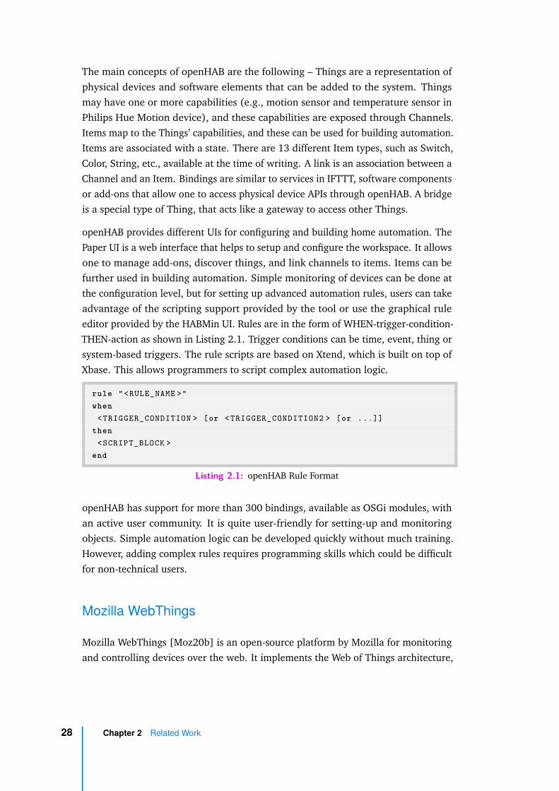
The main concepts of openHAB are the following – Things are a representation ofphysical devices and software elements that can be added to the system. Thingsmay have one or more capabilities (e.g., motion sensor and temperature sensor inPhilips Hue Motion device), and these capabilities are exposed through Channels.Items map to the Things’ capabilities, and these can be used for building automation.Items are associated with a state. There are 13 different Item types, such as Switch,Color, String, etc., available at the time of writing. A link is an association between aChannel and an Item. Bindings are similar to services in IFTTT, software componentsor add-ons that allow one to access physical device APIs through openHAB. A bridgeis a special type of Thing, that acts like a gateway to access other Things.
openHAB provides different UIs for configuring and building home automation. ThePaper UI is a web interface that helps to setup and configure the workspace. It allowsone to manage add-ons, discover things, and link channels to items. Items can befurther used in building automation. Simple monitoring of devices can be done atthe configuration level, but for setting up advanced automation rules, users can takeadvantage of the scripting support provided by the tool or use the graphical ruleeditor provided by the HABMin UI. Rules are in the form of WHEN-trigger-condition-THEN-action as shown in Listing 2.1. Trigger conditions can be time, event, thing orsystem-based triggers. The rule scripts are based on Xtend, which is built on top ofXbase. This allows programmers to script complex automation logic.
rule "<RULE_NAME >"when
<TRIGGER_CONDITION > [or <TRIGGER_CONDITION2 > [or ...]]then
<SCRIPT_BLOCK >end
Listing 2.1: openHAB Rule Format
openHAB has support for more than 300 bindings, available as OSGi modules, withan active user community. It is quite user-friendly for setting-up and monitoringobjects. Simple automation logic can be developed quickly without much training.However, adding complex rules requires programming skills which could be difficultfor non-technical users.
Mozilla WebThings
Mozilla WebThings [Moz20b] is an open-source platform by Mozilla for monitoringand controlling devices over the web. It implements the Web of Things architecture,
28 Chapter 2 Related Work

in which the principles of web are integrated to IoT. The web interface provided bythe project can be used to configure IoT devices and build automation scenarios.
The project has two components, the WebThings Gateway and the WebThingsframework. The Gateway can be installed locally on a low-end device like RaspberryPi. It provides interfaces to monitor and control devices. It has Things UI, a webinterface backed by a rules engine, where users can create rules using a drag anddrop UI. Similar to openHAB binding and IFTTT services, Gateway has an add-onmanagement system that supports a large number of existing IoT devices.
The objects in WebThings are specified using the Mozilla Thing Description specifica-tion. A specification complementary (concrete implementation) to the abstract datamodel provided by the W3C’s Thing Description specification. The description isexposed as a JSON object, through which a device’s capabilities can be understood.The rules engine allows users to create rules in the form of IF-event-THEN-action.The event clause supports conjunction and disjunction of multiple events and actionclause support conjunction of multiple actions. Rules are executed independently,i.e., as and when the event is triggered.
Our work extends Mozilla WebThings, not only because it is open source and backedby Web of Things specification, but also it is very intuitive for end-users to buildautomation scenarios. In our experiments, we noticed that even non-programmerscould start using the tool just after around 10 minutes of training. More detailsregarding the extensions to Mozilla WebThings are available in Chapter 7 describingthe tool support.
Other Automation Tools
There are a few more tools worth mentioning in the section. Here we cover thembriefly, as these tools work on the principles similar to the tools discussed in theearlier section.
Home Assistant [Hom20] is another open source home automation tool that can bedeployed on Raspberry Pi. It provides integrations with more than 1600 services.It has a web UI with the Automation Editor. The Editor allows users to set rules inthe form of Trigger-Condition-Action. There are different types of triggers like time,sunrise/sunset, numeric, state, mqtt etc. Templates can be used to specify modeadvanced triggers. Conditions supported are logical AND, OR, NOT conditions andalso numeric conditions such as time, state etc. The configurations and automationsare saved in YAML format.
2.5 End-User Tools in Smart Homes 29
Samsung SmartThings [Inc20b] is another tool which supports designing of complexrules through webCoRE and SmartRules apps. webCoRE has rules encoded asPistons. Pistons can be created using the Piston Editor UI. SmartRules is a moregraphical option, but it is not as expressive as webCoRE. Apple Workflow [Inc20a]and Microsoft Power Automate (formerly Flow) [Mic20] are automation tools, buttheir focus is mostly on software service level automation.
The two broad reasons for the popularity of the tools mentioned in Section 2.5 are –(i) ease of access (ii) support for a wide range of devices. So, any new tool mustcompete on these metrics to gain traction in the market. Considering these factors,we chose to build a solution on top of an existing platform covering some of itslimitations.
There are a few areas of improvement that we have covered in our work. First, thesetools do not check the validity of the designed application at behaviour level. Thechecks are limited to syntactic checks and matching of ports (data types). Second,simple automation rules are executed independently. There is no easy way tocompose these individual rules to build a more advanced scenario. Further, thesemantics of execution is usually not well defined in the documentation. Finally,most of these tools treat reconfiguration as another deployment of a configuration.There are neither mechanisms to compare an existing and a new configuration noroptions to deploy the new configuration as seamlessly as possible.
2.6 Concluding Remarks
In this chapter, we have covered different areas of work in the literature relatedto our contributions. Our work is distinct from the presented related works inmore than one ways. First, we model the objects and their composition based onthe WoT standard and importantly, our model takes into account the behaviourof the individual objects. By considering the behaviour, the verification is morecomprehensive when compared to the verification at syntactic and rule levels. Withrespect to reconfiguration, we not only propose properties to qualitatively compareconfigurations but also propose mechanisms to deploy new configurations seamlessly.Finally, unlike the tools in the market, our tool integrates formal methods intoapplication design and deployment to provide correctness guarantees at design-time.
30 Chapter 2 Related Work

Background 3„If you do not rest on the good foundation of
nature, you will labour with little honour andless profit.
— Leonardo da VinciItalian polymath
This chapter presents a quick overview of the formal concepts and techniquesused in the subsequent chapters. First, concepts related to formal verification arepresented. A short introduction to Labelled Transition Systems and operations onthem, followed by an overview of the verification techniques are presented. Nextsection covers the LNT language. Model Checking Language (MCL) is described inthe subsequent section. The final section introduces rewriting logic and the Maudesystem. Readers familiar with these tools and techniques, especially from the formalmethods background may safely skip these introductions.
3.1 Behavioural Models
One of the techniques to study the behaviour of a discrete system is by specifying itin terms of a state transition system. The behaviour describes how and when thesystem can interact with its environment [San13]. These systems can be labelledor unlabelled (or label set is a singleton) and in our work we specifically focus ona Labelled Transition System (LTS) as it allows one to distinguish the reasons totrigger the transitions.
Labelled Transition System
An LTS is a 4-tuple consisting of a set of states (S) and a set of transitions (T )between the states. Among the states, one state is identified as an initial state (s0).The transitions are labelled by actions (A). The initial state denotes the state inwhich the system is in before any action is performed on it.
31

Definition 1. Formally, LTS = ⟨S, A, T, s0⟩, where
– S is the set of states
– A is the set of actions
– T ⊆ S × A × S is the transition relation
– s0 ∈ S is the initial state
A transition (s1, a0, s2) (also denoted as s1a0−→ s2), represents a transition represent-
ing that the system can move from a state s1 to another state s2 by performing anaction a0.
An LTS contains all possible execution sequences of a system. An element of this setof all possible finite sequences is called a trace. Given an LTS, a trace is a sequenceof actions a0, a1, ..., an ∈ A, such that s0
a0−→ s1, s1a1−→ s2, ..., sn
an−→ sn+1 ∈ T , wheren ∈ N. The execution sequence in a trace starts from the initial state s0 and the tracecould possibly have infinite sequences due to the presence of loops in the systembehaviour.
Sometimes, it is not possible to know the complete behaviour of a system or moreoften only a subset of system behaviour is of interest to the task. In such instances, aspecial action called internal or hidden action denoted by τ is modelled. These areunobservable actions in the system.
Parallel composition of two LTSs results in an LTS. The composition may involvesynchronization on a subset L ⊆ A1 ∪ A2 of the common actions, with the particularcases of interleaving (L = ∅) and full synchronization (L = A1 ∪ A2).
Definition 2. Given two LTSs, LTS1 = ⟨S1, A1, T1, s01⟩ and LTS2 = ⟨S2, A2, T2, s02⟩where the actions to synchronize are specified by the set L ⊆ A1 ∪ A2. The parallelcomposition (synchronous product) of LTS1 and LTS2, denoted by LTS1 ∥L LTS2
is an LTS = ⟨S, A, T, s0⟩ where:
– S = S1 × S2
– A = A1 ∪ A2
– s0 = ⟨s01, s02⟩
32 Chapter 3 Background

– T ⊆ S × A × S such that
⟨s1, s2⟩ a−→ ⟨s′1, s2⟩ if a ∈ A1 \ L ∧ s1
a−→ s′1
⟨s1, s2⟩ a−→ ⟨s1, s′2⟩ if a ∈ A2 \ L ∧ s2
a−→ s′2
⟨s1, s2⟩ a−→ ⟨s′1, s′
2⟩ if a ∈ L ∧ s1a−→ s′
1 ∧ s2a−→ s′
2
In a composition, the notion of hiding allows one to model internal communicationsof the system. The process of hiding is implemented by renaming visible actions intothe internal action τ .
3.2 LNT Language
LNT [Cha+18; GLS17] is a formal specification language based on the E-LOTOS ISOstandard [ISO01]. It provides constructs derived from imperative and functionalprogramming styles to specify concurrent value-passing systems in a simple mannerwhilst keeping the semantic foundations of process calculi. It is one of the languagessupported by CADP verification toolbox [Gar+13]. The operational semantics ofthe behaviours in LNT are defined in terms of LTSs, i.e., LNT specifications can becompiled to obtain LTSs using CADP compilers. Here we take a look at some of thefeatures of LNT.
Data Types
LNT supports basic data types and constructed data types. The predefined basictypes are Boolean (bool), integer (int), real (real), natural number (nat), character(char), and string (string).
Constructed data types (records, lists, sets, etc.,) can be defined using the typekeyword as illustrated in the listing below. It specifies an enumerated type denotingthree kinds of person that could be present in a home. The with clause is used todefine functions that are automatically declared for the type.
1 type person i s2 re s iden t , guest , i n t rude r3 with " !=" , "=="4 end type
3.2 LNT Language 33

Variables
LNT supports data variables on which read and write operations can be performed.Variables are declared using the var keyword and their scope is defined using the"var ... in ... end var" block.
Variables can be assigned values using the assignment operator := in statements ofthe form X := V, where V is the value to be assigned to the variable X.
1 var presence : person in2 presence := r e s i d e n t3 end var
Statements
Standard control flow structures are supported by LNT. Conditional statementscan be specified using if, and case constructs. Iteration statements can be definedusing loop (general loop), for (stepwise loop), and while (initial condition loop)keywords. Statements can be sequentially composed using ; and the empty statementis denoted by null keyword.
Functions
Functions are defined using the function keyword. Functions support both call-by-value and call-by-reference parameter passing, with call by value being the defaultoption. Call by value and call by reference parameters are denoted by in and outkeywords, respectively. A special keyword inout is used to denote a parameterthat could be both read and updated within the function. In a function call, actualparameter values are prefixed by !, ?, and !? for the in, out, and inout functionparameters, respectively. A function can return a value using the return keyword.
1 function i s _ i n t r u s i o n _ d e t e c t e d ( in presence : person , outl i g h t : co lour ) : bool i s
2 var s t a t u s : bool in3 s t a t u s := fa l se ;4 i f ( presence == r e s i d e n t ) then5 l i g h t := green6 e l s i f ( presence == guest ) then7 l i g h t := blue
34 Chapter 3 Background
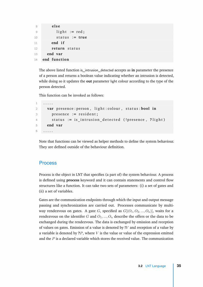
8 else9 l i g h t := red ;
10 s t a t u s := true11 end i f12 return s t a t u s13 end var14 end function
The above listed function is_intrusion_detected accepts as in parameter the presenceof a person and returns a boolean value indicating whether an intrusion is detected,while doing so it updates the out parameter light colour according to the type of theperson detected.
This function can be invoked as follows:
1 . . . . .2 var presence : person , l i g h t : colour , s t a t u s : bool in3 presence := r e s i d e n t ;4 s t a t u s := i s _ i n t r u s i o n _ d e t e c t e d ( !presence , ? l i g h t )5 end var6 . . . . .
Note that functions can be viewed as helper methods to define the system behaviour.They are defined outside of the behaviour definition.
Process
Process is the object in LNT that specifies (a part of) the system behaviour. A processis defined using process keyword and it can contain statements and control flowstructures like a function. It can take two sets of parameters: (i) a set of gates and(ii) a set of variables.
Gates are the communication endpoints through which the input and output messagepassing and synchronization are carried out. Processes communicate by multi-way rendezvous on gates. A gate G, specified as G[(O1, O2, ..., On)], waits for arendezvous on the identifer G and O1, ..., On describe the offers or the data to beexchanged during the rendezvous. The data is exchanged by emission and receptionof values on gates. Emission of a value is denoted by !V and reception of a value bya variable is denoted by ?P , where V is the value or value of the expression emittedand the P is a declared variable which stores the received value. The communication
3.2 LNT Language 35
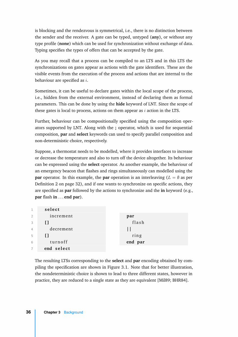
is blocking and the rendezvous is symmetrical, i.e., there is no distinction betweenthe sender and the receiver. A gate can be typed, untyped (any), or without anytype profile (none) which can be used for synchronization without exchange of data.Typing specifies the types of offers that can be accepted by the gate.
As you may recall that a process can be compiled to an LTS and in this LTS thesynchronizations on gates appear as actions with the gate identifiers. These are thevisible events from the execution of the process and actions that are internal to thebehaviour are specified as i.
Sometimes, it can be useful to declare gates within the local scope of the process,i.e., hidden from the external environment, instead of declaring them as formalparameters. This can be done by using the hide keyword of LNT. Since the scope ofthese gates is local to process, actions on them appear as i action in the LTS.
Further, behaviour can be compositionally specified using the composition oper-ators supported by LNT. Along with the ; operator, which is used for sequentialcomposition, par and select keywords can used to specify parallel composition andnon-deterministic choice, respectively.
Suppose, a thermostat needs to be modelled, where it provides interfaces to increaseor decrease the temperature and also to turn off the device altogether. Its behaviourcan be expressed using the select operator. As another example, the behaviour ofan emergency beacon that flashes and rings simultaneously can modelled using thepar operator. In this example, the par operation is an interleaving (L = ∅ as perDefinition 2 on page 32), and if one wants to synchronize on specific actions, theyare specified as par followed by the actions to synchronize and the in keyword (e.g.,par flash in . . . end par).
1 se l ec t2 increment3 []4 decrement5 []6 t u r n o f f7 end se lec t
parf l a s h
||r ing
end par
The resulting LTSs corresponding to the select and par encoding obtained by com-piling the specification are shown in Figure 3.1. Note that for better illustration,the nondeterministic choice is shown to lead to three different states, however inpractice, they are reduced to a single state as they are equivalent [Mil89; BHR84].
36 Chapter 3 Background

Fig. 3.1: Nondeterministic choice and interleaving LTS
Now let us illustrate the LNT process encoding of a physical alarm device interactingwith an environment. An alarm can be set, silenced or turned off completely (e.g.,using a physical button). Silencing of a ringing alarm can be done either using asnooze button, or using a reset button. For the sake of simplicity, let us model thatboth snoozing and resetting the alarm will result in the same state (i.e., hittingsnooze resets the alarm). snooze and reset are specified as a silenceaction enumeratedtype.
1 type s i l e n c e a c t i o n i s2 snooze , r e s e t3 with "==" , " !="4 end type
The behaviour of the alarm is encoded in the process alarm. The possible interactionswith the environment (communication endpoint) are specified in setalarm, silence,turnoff, and ring. The corresponding gates are untyped any. Further, loop is used toencode the repeatable sequence of actions possible in an alarm. Alarm can be eitherset or turned off as encoded using the select operator.
1 process alarm [ seta larm : any , s i l e n c e : any , t u r n o f f : any ,r ing : any] i s
2 loop3 se l ec t4 se ta larm ; r ing ;5 s i l e n c e ( ?any s i l e n c e a c t i o n )6 []7 t u r n o f f8 end se lec t
3.2 LNT Language 37
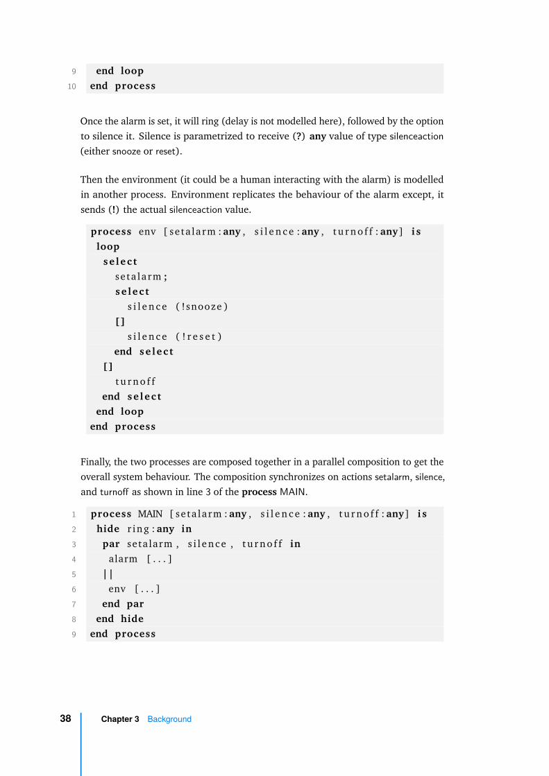
9 end loop10 end process
Once the alarm is set, it will ring (delay is not modelled here), followed by the optionto silence it. Silence is parametrized to receive (?) any value of type silenceaction(either snooze or reset).
Then the environment (it could be a human interacting with the alarm) is modelledin another process. Environment replicates the behaviour of the alarm except, itsends (!) the actual silenceaction value.
process env [ seta larm : any , s i l e n c e : any , t u r n o f f : any] i sloop
se lec tse ta larm ;s e l ec t
s i l e n c e ( !snooze )[]
s i l e n c e ( ! r e s e t )end se lec t
[]t u r n o f f
end se lec tend loop
end process
Finally, the two processes are composed together in a parallel composition to get theoverall system behaviour. The composition synchronizes on actions setalarm, silence,and turnoff as shown in line 3 of the process MAIN.
1 process MAIN [ seta larm : any , s i l e n c e : any , t u r n o f f : any] i s2 hide r ing : any in3 par setalarm , s i l ence , t u r n o f f in4 alarm [ . . . ]5 ||6 env [ . . . ]7 end par8 end hide9 end process
38 Chapter 3 Background

It is to be noted that the ringing of alarm is modelled as an action internal to thesystem (i.e., composition of the alarm and the environment). Therefore, it is hiddenusing the hide keyword in the MAIN process.
Fig. 3.2: Alarm device behaviour
The composition behaviour can be interpreted as an LTS as shown in Figure 3.2. Thehidden action ring appears as an internal transition with label i in the LTS.
3.3 Model Checking
Model checking [BPS01] is an automated verification technique which involves amodel specified as a state-transition system (e.g., LTS) and a formal property thatneeds to be interpreted on the model. The verification involves checking whetherthe property holds for that model.
As illustrated in Figure 3.3, a Model Checker tool takes as input the model andthe property or the specification to be checked. If the property is not satisfied, acounterexample is produced by the Model Checker indicating the behaviour in themodel violating the property. There are many model checking tools available in thecommunity such as CADP, mCRL2, NuSMV, PRISM, SPIN, UPPAAL, etc.
Properties in model checking can intuitively be viewed as the expression of a specificbehaviour in the system. Some examples of properties are: whether the systemreaches deadlock, does the program terminate with correct output, etc. Theseproperties are usually specified in Temporal Logic (TL). The logic specificationdescribes the ordering of states or actions during the execution of the system. It
3.3 Model Checking 39
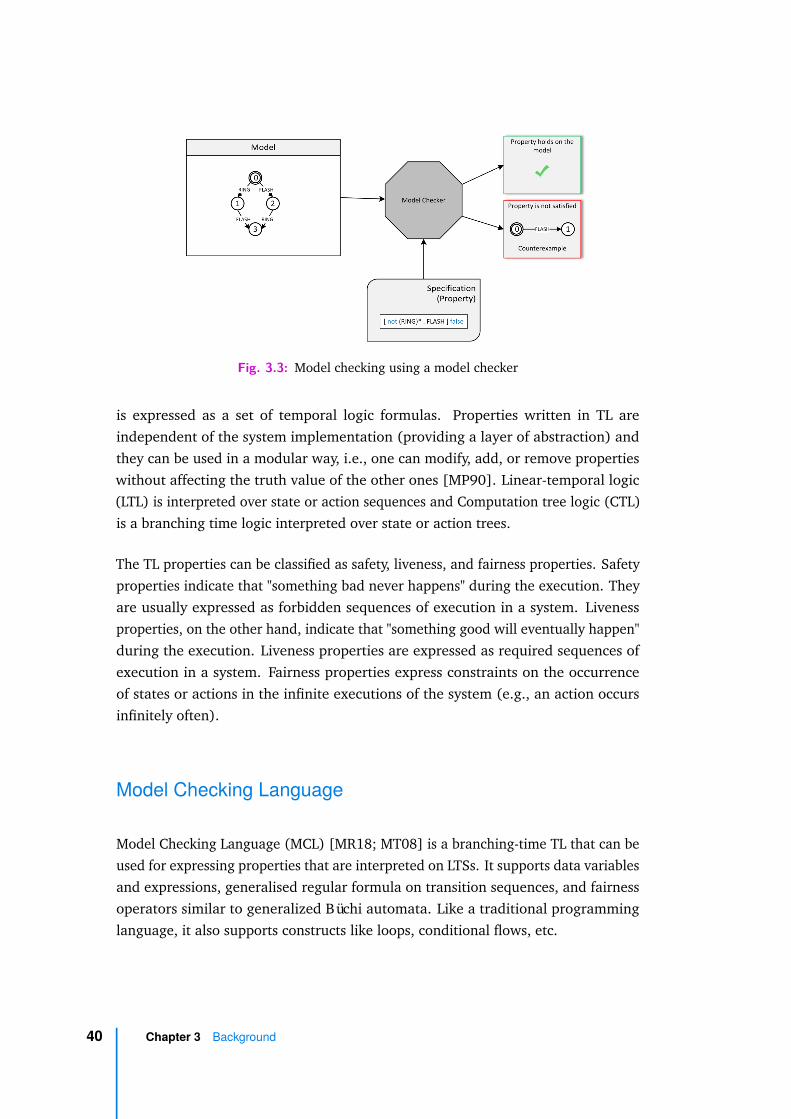
Fig. 3.3: Model checking using a model checker
is expressed as a set of temporal logic formulas. Properties written in TL areindependent of the system implementation (providing a layer of abstraction) andthey can be used in a modular way, i.e., one can modify, add, or remove propertieswithout affecting the truth value of the other ones [MP90]. Linear-temporal logic(LTL) is interpreted over state or action sequences and Computation tree logic (CTL)is a branching time logic interpreted over state or action trees.
The TL properties can be classified as safety, liveness, and fairness properties. Safetyproperties indicate that "something bad never happens" during the execution. Theyare usually expressed as forbidden sequences of execution in a system. Livenessproperties, on the other hand, indicate that "something good will eventually happen"during the execution. Liveness properties are expressed as required sequences ofexecution in a system. Fairness properties express constraints on the occurrenceof states or actions in the infinite executions of the system (e.g., an action occursinfinitely often).
Model Checking Language
Model Checking Language (MCL) [MR18; MT08] is a branching-time TL that can beused for expressing properties that are interpreted on LTSs. It supports data variablesand expressions, generalised regular formula on transition sequences, and fairnessoperators similar to generalized Büchi automata. Like a traditional programminglanguage, it also supports constructs like loops, conditional flows, etc.
40 Chapter 3 Background

MCL formulas are of three different types: action formulas, regular formulas, andstate formulas. Action formulas characterize the actions of the LTS (transition labels).An action pattern {G v} can be used to specify or match all the actions on the LTSassociated to gate G with value v of a particular type. For instance, on the LTSin Figure 3.2, the pattern {SILENCE ?any } matches both SILENCE !RESET andSILENCE !SNOOZE. Action formulas support additional pattern matching throughtwo keywords, any and where. any is a wildcard clause which matches a valueof any type, and where is an option filter clause which is followed by a booleanexpression e (where e), matches an action if and only if the expression e evaluatesto true. For instance, the formula {SILENCE ?act:String where act = “SNOOZE"}is the same as {SILENCE !SNOOZE}. Action formulas can combine action patternsusing the standard Boolean connectives (or, and, implies, not, etc.).
Regular formulas describe transition sequences in the LTS. They are built from actionpatterns and regular expression operators such as or (|), match zero or more (∗),match one or more (+), bounded match ({n}), and concatenate (.). For example,either of the Silence actions in Figure 3.2 can be matched using the | operatoras follows: SETALARM*.({SILENCE !SNOOZE } | {SILENCE !RESET}). Regularformula also supports data handling constructs with variables, conditional flows,and loops.
State formulas, as the name indicate define the predicates over the states of the LTS.They use boolean operators, modalities, fixed-point operators and data handlingconstructs. Modalities such as possibility ⟨E⟩, weak possibility ⟨⟨E⟩⟩, necessity[E], and weak necessity [[E]] can be specified. The infinite looping formula ⟨R⟩@specifies transition sequences with infinite concatenation of sub-sequences thatsatisfy the regular formula R. Safety properties can be expressed as [R]false andliveness properties using the inev operator as [R] inev(A), where A is the actionthat is inevitably reached. In Figure 3.2, a safety property would be to check thatif the alarm is not set, then it cannot be silenced. This can be expressed as [(not{ SETALARM })*.{ SILENCE ?any }] false. The inevitability of occurrence of anaction such as the alarm will always be silenced once it is set can be specified as[true*.{ SETALARM } ] inev({SILENCE ?any}), where inev(A) = mu X. ⟨ true⟩true and [not(A)]X. Properties such as deadlock freedom can be expressed as astate formula: ⟨true⟩ true, which specifies every state as at least one successor (i.e.,no sink state).
The latest version of MCL (V5) [MR18] provides a probabilistic operator to specifyprobability of transition sequences in a probabilistic transition system (PTS). Theoperator is a state formula defined using the prob keyword containing a regular
3.3 Model Checking 41

formula characterizing the required sequence. MCL is equipped with the Evaluatormodel checker [MR18; MT08], which evaluates MCL formulas on the fly on a LTSand generates diagnostics (counterexamples and witnesses). Evaluator also allowsto define derived operators as macros and to group them into reusable libraries.
3.4 Rewriting Logic
Rewriting logic is a logic built to reason about change in a concurrent system [Mes92;Mes12]. It consists of rewrite rules, which are equations used to reason about thechange. Rewriting logic can model the static and dynamic elements of a system.Static elements refer to the states of the system and the dynamic elements are thetransitions in the concurrent system.
A rewriting system R = (O, E, R), where
– O is the set of typed operators
– E is the set of equations that specify the algebraic identities
– R is the set of rewrite rules
A state in rewriting logic is represented mathematically as an algebraic expressionbuilt using the operators specified in O. The states satisfy the algebraic identitiesspecified in E. The set of rewrite rules R represent the evolution of the states. Itspecifies the transitions between the states. In this representation, two states s1 ands2 describe the same state iff s1 ≡ s2 can be proven using E.
The rewrite rule w is implemented through a substitution operation σ. Substitutionmaps variables xi to terms ti. The term substitution tσ replaces all occurrences ofxi by terms ti following the mapping {x1 → t1, x2 → t2, . . . xn → tn}. A rewriteoperation is following the rule w = l → r is denoted by s → t, where s is an instanceof lσ and t is lσ being replaced by rσ. Rewriting can be done in one step or manybut finite steps.
Maude System
Maude is a language and system based on rewriting logic [Cla+07]. It providesa formal toolbox in which Maude can be used as declarative language to specifyan executable formal specification. It has a formal verification system to performanalysis on the specification. Maude integrates an equational style of functional
42 Chapter 3 Background

programming with rewriting logic computation. Maude implements Membershipequational logic, which is a Horn logic [Hor51] whose atomic sentences are equalitiest = t′ and membership assertions of the form t : S , stating that a term t has sort S. Itextends order-sorted equational logic, and supports sorts, subsort relations, subsortpolymorphic overloading of operators, and the definition of partial functions withequationally defined domains.
Maude uses modules as the basic unit of specification and programming. A modulecontains the syntax declarations describing the language of the system, statementsthat assert the properties of the system. The declarations are called signatures whichdefine sorts, subsorts, kinds, and operators. Sorts identify the typed data and Subsortsorganize the data types in a hierarchy. Kinds declare the error types. Operatorsidentified by names operate on data to build expressions. The modules in Maudeare categorized into functional and system modules. Functional modules containequations, data identifiers, and memberships describing the typing informationof a data. System modules contain the rules that describe the evolution of states(transitions), in addition to the elements of the functional module. Functionalmodules are declared using fmod keyword and system modules are declared withmod keyword.
fmod ID i ssort Id .
endfm
In the above listing a functional module ID is declared which contains a sort Id. It isdeclared using the sort keyword followed by an identifier followed by space and aperiod.
Operators in Maude are declared using the op keyword. The keyword is followed bythe operator name, then a colon (:) followed by its sorts as arguments. The resultingsort of the operation is indicated on the right side of arrow ->, which is followed byspace and a period, as with any declaration.
op _+_ : Nat Nat −> Nat .
Operator + defines an addition operator, which takes two natural numbers asarguments and returns a natural number as the result of the operation.
Variables in Maude are declared using the var keyword. Each variable is bound tothe type that it has been declared with. Multiple variables of the same sort can bedeclared with the vars keyword.
var N : Nat .vars M N : Nat .
3.4 Rewriting Logic 43

Unconditional equations in Maude are declared using the eq keyword. The equationshave the following syntax:
eq term1 = term2 [ S ta tementA t t r i bu te s ]
The terms term1 and term2 must have the same kind.
The modules in Maude can be imported as submodules in another module in threedifferent modes: protecting, extending, or including, denoted by keywords pr, ex,and inc, respectively. Protecting mode which is used in our work, indicates thatwhen the module is imported, its ground terms are unaffected by the definitions inthe importing module.
fmod FIBONACCI i spr NAT .op f i b o : Nat −> Nat .
var N : Nat .eq f i b o (0) = 0 .eq f i b o (1) = 1 .eq f i b o ( s s N) = f i b o (N) + f i b o ( s N) .
endfm
Listing 3.1: Fibonacci sequence in Maude
Listing 3.1 shows the Maude specification of the Fibonacci series. It has the sortNAT in protecting mode. The operator fibo takes a natural number as argumentand returns the next natural number in the series. The unconditional equationsdefined using the eq keyword specify the constraints of the Fibonacci sequence. It isto be noted that here we describe only the equational logic in Maude but Maudealso supports rewrite rules and readers interested in further reading can refer to theMaude manual [Cla+07].
44 Chapter 3 Background

A Formal Model for the Webof Things
4
„It’s on the strength of observation and reflectionthat one finds a way. So we must dig and delveunceasingly.
— Claude MonetFrench painter
The IoT ecosystem is built using a set of diverse standards and protocols. Thereare many works focusing on providing a common standard for interacting withobjects and enabling objects with different underlying protocols to be interoperable.Standards such as Constrained Application Protocol (CoAP) by Constrained RESTfulEnvironments group (CoRE), OpenWeave Weave Schema Description Language(WDL) by Google [Nes20], Web of Things (WoT) [W3C20c] by the World Wide WebConsortium (W3C), etc., describe objects in a machine-readable format like JSON.This description specifies the object’s capabilities, and also describes the ways tointeract with it in a standardized manner. This information helps to know the objectbehaviour as it describes how and when the object can interact with the externalworld (environment).
This chapter begins with an introduction to the WoT specification which we usein our work. This is useful in understanding the various components of the WoTarchitecture. Specifically, we detail the Thing Description (TD) specification. In thenext section, we present a behaviour model for objects which is based on the WoTTD specification. Building a model based on a standard makes our approach widelyapplicable and specifically WoT offers a standard that is open, and it has a number ofconcrete implementations available as open-source tools for experiments and furtherextensions. Since Event-Condition-Action (ECA) [DGG95] programming is popularin smart homes, we extend the notion of rule-based ECA programming by defininga language for composition of ECA rules. This language enables users to build orprogram more expressive automation scenarios in their homes. Further, we describethe operational semantics specifying the execution of an IoT application which iscomposed of ECA rules. In the final two sections we encode the models of objects,
45
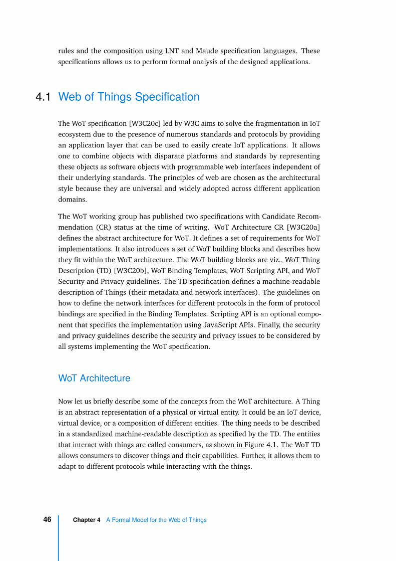
rules and the composition using LNT and Maude specification languages. Thesespecifications allows us to perform formal analysis of the designed applications.
4.1 Web of Things Specification
The WoT specification [W3C20c] led by W3C aims to solve the fragmentation in IoTecosystem due to the presence of numerous standards and protocols by providingan application layer that can be used to easily create IoT applications. It allowsone to combine objects with disparate platforms and standards by representingthese objects as software objects with programmable web interfaces independent oftheir underlying standards. The principles of web are chosen as the architecturalstyle because they are universal and widely adopted across different applicationdomains.
The WoT working group has published two specifications with Candidate Recom-mendation (CR) status at the time of writing. WoT Architecture CR [W3C20a]defines the abstract architecture for WoT. It defines a set of requirements for WoTimplementations. It also introduces a set of WoT building blocks and describes howthey fit within the WoT architecture. The WoT building blocks are viz., WoT ThingDescription (TD) [W3C20b], WoT Binding Templates, WoT Scripting API, and WoTSecurity and Privacy guidelines. The TD specification defines a machine-readabledescription of Things (their metadata and network interfaces). The guidelines onhow to define the network interfaces for different protocols in the form of protocolbindings are specified in the Binding Templates. Scripting API is an optional compo-nent that specifies the implementation using JavaScript APIs. Finally, the securityand privacy guidelines describe the security and privacy issues to be considered byall systems implementing the WoT specification.
WoT Architecture
Now let us briefly describe some of the concepts from the WoT architecture. A Thingis an abstract representation of a physical or virtual entity. It could be an IoT device,virtual device, or a composition of different entities. The thing needs to be describedin a standardized machine-readable description as specified by the TD. The entitiesthat interact with things are called consumers, as shown in Figure 4.1. The WoT TDallows consumers to discover things and their capabilities. Further, it allows them toadapt to different protocols while interacting with the things.
46 Chapter 4 A Formal Model for the Web of Things
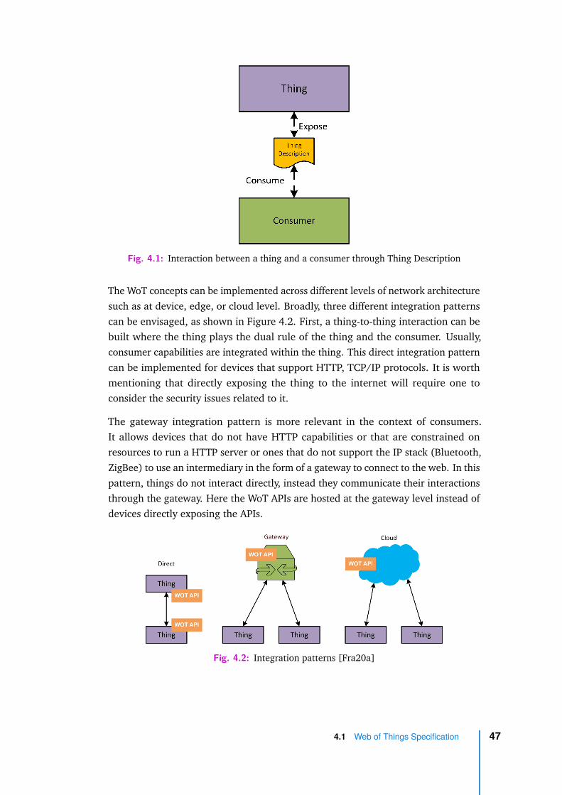
Fig. 4.1: Interaction between a thing and a consumer through Thing Description
The WoT concepts can be implemented across different levels of network architecturesuch as at device, edge, or cloud level. Broadly, three different integration patternscan be envisaged, as shown in Figure 4.2. First, a thing-to-thing interaction can bebuilt where the thing plays the dual rule of the thing and the consumer. Usually,consumer capabilities are integrated within the thing. This direct integration patterncan be implemented for devices that support HTTP, TCP/IP protocols. It is worthmentioning that directly exposing the thing to the internet will require one toconsider the security issues related to it.
The gateway integration pattern is more relevant in the context of consumers.It allows devices that do not have HTTP capabilities or that are constrained onresources to run a HTTP server or ones that do not support the IP stack (Bluetooth,ZigBee) to use an intermediary in the form of a gateway to connect to the web. In thispattern, things do not interact directly, instead they communicate their interactionsthrough the gateway. Here the WoT APIs are hosted at the gateway level instead ofdevices directly exposing the APIs.
Fig. 4.2: Integration patterns [Fra20a]
4.1 Web of Things Specification 47

Finally, the cloud integration pattern is a scalable architecture that connects thingswith the cloud. It is similar to a gateway wherein the cloud service acts as theintermediary. This pattern is useful for large scale deployments, especially across awide geographical area and also when things need access to powerful computingcapabilities (e.g., video recognition).
In this work, we model a gateway pattern which allows us to use both IP and non-IPdevices but without having to rely on cloud service providers. It is also easier toimplement features at the gateway level, as we have more control of the system.Moreover, as both gateway and cloud can be viewed as an intermediary, the broadcharacteristics of the model remain somewhat similar and thus the approach isapplicable to cloud as well.
The W3C WoT specification provides an abstract data model and architecture. Forreal world deployments, we need to use a concrete implementation that providesa JSON serialization of TD and an implementation of protocol bindings, such asHTTP and WebSockets. Mozilla WebThings [Moz20b] is a project by Mozilla thatprovides an implementation based on WoT specification. We built our work on thebasis of this project instead of building our own concrete implementation to avoidduplication of work. Since the Mozilla implementation is open source, it gives usthe flexibility to customize the application to our needs. In the subsequent section,we describe the Mozilla WoT TD [Fra20b] and Web Thing API [Fra20b] which are aconcrete JSON serialization of the WoT TD specification and an implementation ofthe WoT protocol bindings using existing web technologies.
Thing Description
The TD specification describes the metadata of things in a machine readable JSONencoding. Here we describe some of the key elements in a TD. Listing 4.1 showsthe partial thing description of a connected light. The important elements of the TDare Properties, Events and Actions. These are the three interaction affordances thatcan be used to interact with the device. An affordance refers to the fundamentalproperties that determine how the thing could possibly be used [Nor88]. The listinghas two properties on and brightness, an action fade, and an event overheated.
@context is the reference to the semantic schema that defines the different typesof object capabilities. There are different IoT schemas such as IoT Schema [Sch20]and Mozilla Schema [Moz20a].
48 Chapter 4 A Formal Model for the Web of Things
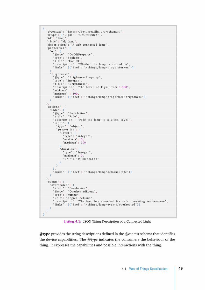
{" @context " : " h t tp s : // i o t . moz i l l a . org /schemas / " ," @type " : [ " L igh t " , " OnOffSwitch " ] ," id " : " lamp " ," t i t l e " : "My Lamp" ," d e s c r i p t i o n " : "A web connected lamp " ," p r o p e r t i e s " : {
" on " : {" @type " : " OnOffProperty " ," type " : " boolean " ," t i t l e " : "On/ Off " ," d e s c r i p t i o n " : " Whether the lamp i s turned on " ," l i n k s " : [ { " hre f " : " / th ings /lamp/ p r o p e r t i e s /on " } ]
} ," b r i gh tne s s " : {
" @type " : " B r i gh tnes sP roper t y " ," type " : " i n t e g e r " ," t i t l e " : " B r i gh tnes s " ," d e s c r i p t i o n " : " The l e v e l of l i g h t from 0−100 " ,"minimum" : 0 ,"maximum" : 100 ," l i n k s " : [ { " hre f " : " / th ings /lamp/ p r o p e r t i e s / b r i gh tne s s " } ]
}} ," a c t i o n s " : {
" fade " : {" @type " : " FadeAction " ," t i t l e " : " Fade " ," d e s c r i p t i o n " : " Fade the lamp to a given l e v e l " ," input " : {
" type " : " o b j e c t " ," p r o p e r t i e s " : {
" l e v e l " : {" type " : " i n t e g e r " ,"minimum" : 0 ,"maximum" : 100
} ," durat ion " : {
" type " : " i n t e g e r " ,"minimum" : 0 ," un i t " : " m i l l i s e c o n d s "
}}
} ," l i n k s " : [ { " hre f " : " / th ings /lamp/ a c t i o n s / fade " } ]
}} ," events " : {
" overheated " : {" t i t l e " : " Overheated " ," @type " : " OverheatedEvent " ," type " : " number " ," un i t " : " degree c e l s i u s " ," d e s c r i p t i o n " : " The lamp has exceeded i t s s a f e opera t ing temperature " ," l i n k s " : [ { " hre f " : " / th ings /lamp/ events / overheated " } ]
}}
}
Listing 4.1: JSON Thing Description of a Connected Light
@type provides the string descriptions defined in the @context schema that identifiesthe device capabilities. The @type indicates the consumers the behaviour of thething. It expresses the capabilities and possible interactions with the thing.
4.1 Web of Things Specification 49

Properties affordance exposes the state of the thing to the consumer. Propertiescan be read by the consumer(and in some cases, also updated). Things can makethe properties observable upon a change of state. Properties can be viewed as theattributes of the device. Each property has a primitive type (String, Integer, Boolean,etc.) and a semantic @type defined by the semantic schema.
Events describe the events than can be emitted by the device. The data from eventsare asynchronously logged and they can be processed by the consumers. Typically,events can be used to describe changes to more than one property or to describe achange in state that cannot be specified by change in properties. In Listing 4.1, theevent overheated is of semantic @type OverheatedEvent, which is different from theproperties.
Actions describes the functions that can be invoked on the thing to affect a changein state of the device. Actions can be used to invoke changes that manipulate statesor trigger a change over time (process) on the object. Usually, these changes cannotbe done by setting of properties. In the case of the light in Listing 4.1, the fade actionmanipulates two properties: brightness level and duration.
The WebThings API provides mechanisms to modify properties, read events, andsend action requests by exposing the affordances as REST (representational statetransfer) resources. The events resource exposes a log of events recently emitted bythe device and actions resource provides access to queue of actions to be executedon a device.
4.2 Model for IoT Objects
The behavioural model of the objects is based on the TD of the object. Here wedefine the model and other components that form a composition of objects.
Definition 3 (Property). Let K be the set of property identifiers, and for any k ∈ K,let Vk be the domain of values associated to k. A property p is a pair (k, v), wherek ∈ K is the identifier of the property and v ∈ Vk its value.
A property refers to the state attributes of the device. It maps to the interactionaffordances in the TD. Typically, IoT objects perform the role of a sensor or anactuator. This behaviour can be viewed as objects having state attributes whosevalues change over a period of time when they interact with the external world.
50 Chapter 4 A Formal Model for the Web of Things
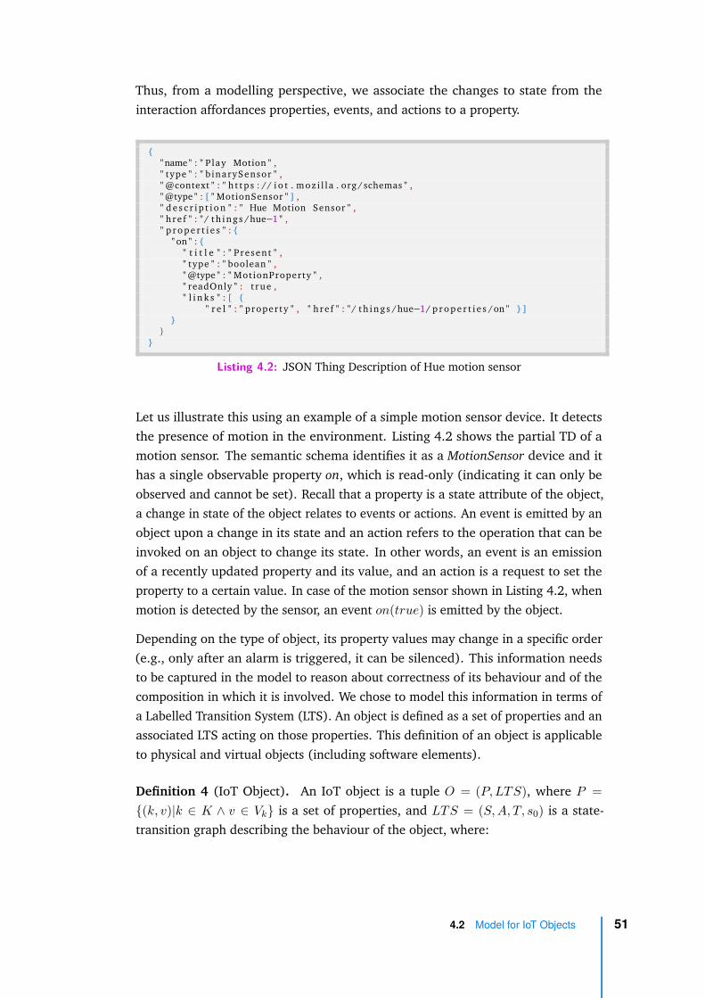
Thus, from a modelling perspective, we associate the changes to state from theinteraction affordances properties, events, and actions to a property.
{"name" : " P lay Motion " ," type " : " b inarySensor " ," @context " : " h t tp s : // i o t . moz i l l a . org /schemas " ," @type " : [ " MotionSensor " ] ," d e s c r i p t i o n " : " Hue Motion Sensor " ," h re f " : " / th ings /hue−1 " ," p r o p e r t i e s " : {
" on " : {" t i t l e " : " Present " ," type " : " boolean " ," @type " : " MotionProperty " ," readOnly " : t rue ," l i n k s " : [ {
" r e l " : " proper ty " , " h re f " : " / th ings /hue−1/ p r o p e r t i e s /on " } ]}
}}
Listing 4.2: JSON Thing Description of Hue motion sensor
Let us illustrate this using an example of a simple motion sensor device. It detectsthe presence of motion in the environment. Listing 4.2 shows the partial TD of amotion sensor. The semantic schema identifies it as a MotionSensor device and ithas a single observable property on, which is read-only (indicating it can only beobserved and cannot be set). Recall that a property is a state attribute of the object,a change in state of the object relates to events or actions. An event is emitted by anobject upon a change in its state and an action refers to the operation that can beinvoked on an object to change its state. In other words, an event is an emissionof a recently updated property and its value, and an action is a request to set theproperty to a certain value. In case of the motion sensor shown in Listing 4.2, whenmotion is detected by the sensor, an event on(true) is emitted by the object.
Depending on the type of object, its property values may change in a specific order(e.g., only after an alarm is triggered, it can be silenced). This information needsto be captured in the model to reason about correctness of its behaviour and of thecomposition in which it is involved. We chose to model this information in terms ofa Labelled Transition System (LTS). An object is defined as a set of properties and anassociated LTS acting on those properties. This definition of an object is applicableto physical and virtual objects (including software elements).
Definition 4 (IoT Object). An IoT object is a tuple O = (P, LTS), where P ={(k, v)|k ∈ K ∧ v ∈ Vk} is a set of properties, and LTS = (S, A, T, s0) is a state-transition graph describing the behaviour of the object, where:
4.2 Model for IoT Objects 51

– S is a set of states. Each state is a function s : K →⋃︁
k∈K Vk s.t. s(k) ∈ Vk;
– A = {(d k(v))|d ∈ {event, action}∧k ∈ K ∧v ∈ Vk} is a set of property labels;
– T ⊆ S × A × S is the transition relation. A transition (s1, (d, k(v)), s2) ∈ T
(also noted s1d k(v)−−−→ s2) indicates that the move from state s1 to state s2 is
either an event or an action denoted by d and its associated property named k.T = {(s event k(v)−−−−−−→ s)}
⋃︁{(s action k(v)−−−−−−→ s[v/k])}, where s[v/k] indicates that the
value of property k is updated to v;
– s0 ∈ S is the initial state, with initial values s0(k) = v0k for all k ∈ K.
This behavioural model of an object can be derived by extracting certain valuesfrom its TD JSON. The Properties attribute in the TD maps to the Properties inthe behavioural model, which form the labels of the LTS. @type semantic attributeprovides information on the order in which these labels appear in the LTS. In caseof simple objects, such as sensors and actuators, the model can be automaticallygenerated as the behaviour is directly inferred from Definition 4 by considering allthe (relevant) values for each property of the object. Figure 4.3 shows a simplifiedbehavioural model of a motion sensor. In the TD of a motion sensor, there is aBoolean property on which represents whether a motion is detected by the object.Initially, the on property is in false state (s0), denoted by concentric circles, and itcan receive an action and set the on value to true. Once the value is set, it emits theevent notifying the change in state.
Fig. 4.3: Labelled transition system of a motion sensor
In case of complex objects, an expert can model the behaviour taking into account thesemantic @type and also the object behaviour, which can be either described manu-ally or can be learnt using appropriate automata learning frameworks [IHS15].
52 Chapter 4 A Formal Model for the Web of Things

4.3 ECA Rules and a Language for Composition
The composition of objects is built by combining the objects through Event-Condition-Action (ECA) rules. ECA rules are of the form IF something-happens THEN do-something. An ECA rule is triggered when an event emitted by a specific objectsatisfies certain condition(s) and, as a reaction, an action is sent to another objectdefined as target. Note that for the sake of simplicity, we denote an event and itstrigger conditions as EVT and an action and its attributes as ACT in the subsequenttext.
Definition 5 (Rule). Given a set of objects {O1, . . . , On}, Oi = (P i, (Si, Ai, T i, si0)),
a rule R is defined as “IF EVT THEN ACT” where,EVT ::= event | EVT1 ∧ EVT2 | EVT1 ∨ EVT2,ACT ::= action | ACT1 ∧ ACT2,event ::= Oi(k, v), where (k, v) ∈ P i,action ::= Oj(k, v), where (k, v) ∈ P j .
Here the ECA rules support the conjunction and disjunction of events in the EVTclause. However, it is to be noted that ∨ operator is not available in the ACT clauseas introducing it will result in nondeterministic decisions. By allowing these logicalconnectives, one can combine events or actions from different objects and buildmore expressive automation scenarios.
A smart environment setup can contain a number of rules ranging from a dozen toa few hundreds, whereas a specific application involves only a few rules from allthe available rules. Typically, these rules are executed in parallel, i.e., as and whenthe event triggers of a rule are satisfied, it gets executed. This execution modelis simple, but it limits the expressiveness as one cannot define a specific order ofexecution of rules. There are many works in the literature that have identified thelimits of expressiveness in ECA rules [Ur+16; HC15; Bri+17]. To be able to specifymore expressive automation scenarios, we use a composition language with simpleoperators based on regular expressions.
Definition 6 (Composition Language). A composition C is an expression built overa set of rules R using the operators Sequence (;), Choice (+), Parallel (||), andRepeat ( k) :
C ::= R | C1; C2 | C1 + C2 | C1||C2 | Ck1
where,C1; C2 represents a composition expression C1 followed by C2,
4.3 ECA Rules and a Language for Composition 53

C1 + C2 represents a choice between expressions C1 and C2,C1||C2 represents the concurrent execution of expressions C1 and C2, andCk
1 represents the execution k times of a composition expression C1.
The sequence operator (;) allows one to define an order for the execution of rules.It is useful in modelling scenarios where automation follows a sequence, e.g., turnon the light as one enters the room and then if it is cold (temperature < 20), turnon the heater whenever someone is inside the room. The choice operator (+)enables one to execute a rule from a set of rules in a group. Here the choice isan exclusive choice meaning only one rule from the group is executed on a first-come-first-serve basis, whereas an inclusive choice would have executed all the rulessatisfying the trigger conditions. Choice is particularly useful when one has to buildan automation involving a set of events that result in different actions. If one justneeds to capture a set of events that result in a certain action, then using a single rulewith the events in disjunction would be a simpler option. The parallel operator (||)indicates that all the rules (compositions) in the operands are executed, irrespectiveof their order of execution. It is to be noted that both in parallel (||) operator andconjunction (∧) of events, the behaviour is not time bound, i.e., the rules can executeat any point in time and there will not be a timeout if a rule operand executes andremaining operands do not execute after a certain time. Finally, the repeat operatorCk introduces bounded looping of the rules. The composition as a whole is runinfinitely, which is useful in automating routine tasks.
Example: In a retirement home, once the old age pensioner unlocks the door ofher/his apartment, the passage light is turned on. Once she/he sits on the sofa,window blinds are opened for sunlight. At the same time, if the outdoor air qualityis measured to be good by an Air Quality Monitor (AQM), then a window is opened,otherwise the Heating, Ventilation, and Air Conditioning (HVAC) system is turnedon to maintain optimum room condition. Finally, if she/he exits the house, the lightand HVAC are turned off, and the window is closed. The ECA rules corresponding tothe scenario are shown in Listing 4.3. Events and actions are described in the formatobject(property, value). The IoT application can be expressed using the compositionlanguage as follows: R1; (R2||(R3 + R4)); R5.
1 R1 : IF door (open , t rue ) THEN l i g h t (on , t rue )2 R2 : IF so fa (on , t rue ) THEN window( bl inds , t rue )3 R3 : IF AQM( qua l i t y , 0 ) THEN HVAC(on , t rue )4 R4 : IF AQM( qua l i t y , 1 ) THEN window(open , t rue )5 R5 : IF door (open , f a l s e ) THEN l i g h t (on , f a l s e ) ∧ HVAC(on , f a l s e )6 ∧ window(open , f a l s e )
54 Chapter 4 A Formal Model for the Web of Things
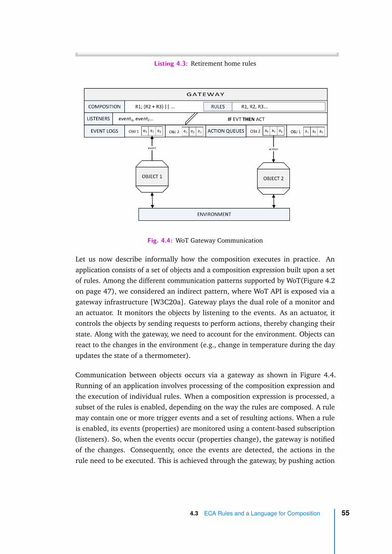
Listing 4.3: Retirement home rules
Fig. 4.4: WoT Gateway Communication
Let us now describe informally how the composition executes in practice. Anapplication consists of a set of objects and a composition expression built upon a setof rules. Among the different communication patterns supported by WoT(Figure 4.2on page 47), we considered an indirect pattern, where WoT API is exposed via agateway infrastructure [W3C20a]. Gateway plays the dual role of a monitor andan actuator. It monitors the objects by listening to the events. As an actuator, itcontrols the objects by sending requests to perform actions, thereby changing theirstate. Along with the gateway, we need to account for the environment. Objects canreact to the changes in the environment (e.g., change in temperature during the dayupdates the state of a thermometer).
Communication between objects occurs via a gateway as shown in Figure 4.4.Running of an application involves processing of the composition expression andthe execution of individual rules. When a composition expression is processed, asubset of the rules is enabled, depending on the way the rules are composed. A rulemay contain one or more trigger events and a set of resulting actions. When a ruleis enabled, its events (properties) are monitored using a content-based subscription(listeners). So, when the events occur (properties change), the gateway is notifiedof the changes. Consequently, once the events are detected, the actions in therule need to be executed. This is achieved through the gateway, by pushing action
4.3 ECA Rules and a Language for Composition 55

requests to the corresponding action queues of the objects. These actions (request toupdate property values) are executed when objects consume the requests from theirqueues. As the processing of the composition expression proceeds, a relevant subsetof rules is enabled and disabled by the gateway components. The environmenthowever, interacts directly with the objects, thereby bypassing the gateway. It isworth recalling that the composition always terminates and the composition asa whole can be executed infinitely. The bound k in Ck ensures that a part of thecomposition is not executed infinitely, thereby allowing the execution of the completeexpression.
Semantics of Composition Expressions
Here we formally define the operational semantics of the composition language. Theexecution is defined with the help of two functions active and exec. These functionsare later used in the inference rules that define the operational semantics.
During the execution of the composition expression, generally only a part of theexpression is active. The function active determines the set of rules that are active ina composition expression (i.e., ready to be executed). This function is defined accord-ing to the different composition operators in Table 4.1. For instance, active(C1; C2)will result in only a first part of the sequence expression (C1) being active, whereasfor choice (+) and parallel operators (∥), the parts of expression operands on eithersides will be active.
Expression Active Rules
active(R) {R}
active(C1; C2) active(C1)
active(C1 + C2) active(C1) ∪ active(C2)
active(C1∥C2) active(C1) ∪ active(C2)Tab. 4.1: Rule activation patterns
Now let us look at how the active function works in the IoT application correspondingto the example automation scenario in Listing 4.3 on page 54. The scenario is shownas a workflow in Figure 4.5. The execution begins where initially, only the ruleR1 is active and once the rule R1 is executed, the rules R2, R3, and R4 are active.Either of the rules R3 or R4 will be triggered, along with the rule R2. Finally, R5 isactivated with all the other rules being inactive.
56 Chapter 4 A Formal Model for the Web of Things

Fig. 4.5: Workflow representing retirement home rules
Further, the execution of the rules can be expressed in terms of a function exec,which generates the (set of) residual(s) of executing a rule R in a compositionexpression C. The rule execution patterns are defined in Table 4.2. Readers maynotice that we do not explicitly define the exec on the repeat operator Ck. Sinceit is a bounded repeat, it can be viewed as a bounded sequential execution of theexpression, i.e., C; . . . . . . ; C⏞ ⏟⏟ ⏞
k times
.
Rule Expression Execution Residual
exec(R, R) {✓}
exec(R, C1; C2) {C; C2|C ∈ exec(R, C1)}
exec(R, C1 + C2) exec(R, C1) ∪ exec(R, C2)
exec(R, C1∥C2) {C′1∥C2|C ′
1 ∈ exec(R, C1)} ∪ {C1∥C′2|C ′
2 ∈ exec(R, C2)}Tab. 4.2: Rule execution patterns
The function exec operates on the rule R to be executed in the composition ex-pression C and therefore R ∈ active(C). The execution of the expression is theexecution of the individual rules. ✓ is a special composition operator which we useto denote the successful execution of a rule (termination). The operator ✓ acts as aneutral element for the binary composition operators:✓
⨁︁C == C, where
⨁︁∈ {; , +, ∥}.
Let us illustrate the execution of the composition expression of the retirement homescenario in Listing 4.3 on page 54. The execution of the expression R1; (R2||(R3 +R4)); R5 is shown in Figure 4.6 on page 59. The execution of an active rule R
produces a transition labelled by R from the current composition expression toone of its residuals. Using the two functions active and exec, the execution of acomposition expression is defined by the following rule:
4.3 ECA Rules and a Language for Composition 57

R ∈ active(C) ∧ C ′ ∈ exec(R, C)
CR−→ C ′
The figure starts with the application of the exec function on the sequence (R1; (. . .)),whose only active rule is R1. The steps of execution of the first part of the composi-tion are as follows:
C = R1; (R2||(R3 + R4)); R5
active(C) = {R1}
exec(R1, C) = {C; (R2||(R3 + R4)); R5|C ∈ exec(R1, R1)}
= {C; (R2||(R3 + R4)); R5|C ∈ {✓}}
= {✓; (R2||(R3 + R4)); R5}
= {(R2||(R3 + R4)); R5}
Subsequently, the remaining part of the composition expression is processed. Inthe Figure 4.6 on the facing page, the solid connectors with rule identifier denotethe execution of the rule and dotted connectors represent the internal executionsteps. As illustrated in the figure, after executing R1, three different three differentrules R2, R3, and R4 become active. The expressions with a strike-through denotethe empty residual (∅) as a result of inactive rule execution. Here we make a slightabuse of notation by overloading the composition operators with sets of compositionexpression (produced by the exec function) as operands on either sides, but this isdone to illustrate the execution in a simplified manner. The empty set ∅ acts as azero element for binary composition operators, i.e.,
∅⨁︂
C == ∅, where⨁︂
∈ {; , +, ∥}
The results of execution are highlighted in solid boxes and dotted boxes are theresults of intermediate steps.
A simplified view of the execution represented as an LTS can be seen in Figure 4.7.Here we can notice the diamond pattern (interleaving) associated with the choiceand the parallel execution.
58 Chapter 4 A Formal Model for the Web of Things
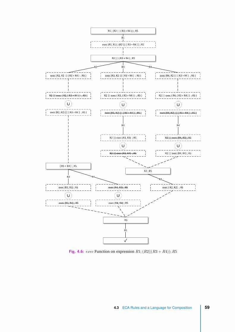
Fig. 4.6: exec Function on expression R1; (R2||(R3 + R4)); R5
4.3 ECA Rules and a Language for Composition 59
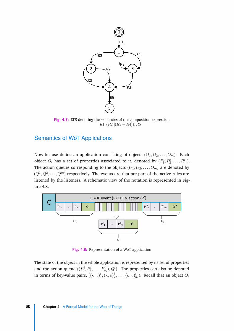
Fig. 4.7: LTS denoting the semantics of the composition expressionR1; (R2||(R3 + R4)); R5
Semantics of WoT Applications
Now let use define an application consisting of objects (O1, O2, . . . , Om). Eachobject Oi has a set of properties associated to it, denoted by (P i
1, P i2, . . . , P i
ni).
The action queues corresponding to the objects (O1, O2, . . . , Om) are denoted by(Q1, Q2, . . . , Qm) respectively. The events are that are part of the active rules arelistened by the listeners. A schematic view of the notation is represented in Fig-ure 4.8.
Fig. 4.8: Representation of a WoT application
The state of the object in the whole application is represented by its set of propertiesand the action queue ((P i
1, P i2, . . . , P i
ni), Qi). The properties can also be denoted
in terms of key-value pairs, ((κ, v)i1, (κ, v)i
2, . . . , (κ, v)ini
). Recall that an object Oi
60 Chapter 4 A Formal Model for the Web of Things

has an LTSi = (Si, Ai, T i, si0), whose states are given by the properties of Oi, i.e.,
(P i1, P i
2, . . . , P ini
) ∈ Si.
The execution of a ECA rule having an event and action can be expressed in termsof two inference rules, one inference rule for triggering the event and another forthe consuming the action from the object queue. The environment action, whichis a special type of action bypassing the object queues, follows a slightly differentexecution semantics.
Before we define the inference rules, let us denote the application state as follows:
⟨((P 11 , .., P 1
n1), Q1), .., ((P k1 , .., P k
i , .., P knk
), Qk), .., ((P m1 , .., P m
i , .., P mnm
), Qm), .., C⟩
where the superscript indexes 1, k, m represent the objects O1, Ok, Om respectivelyand their queues are denoted by Q with the superscript index of the object.
The triggering of an ECA rule R expressed in the form IF event(P ki ) THEN action(P l
j)is given by the following inference rule TRIGGER-EVENT:
R = IF event(P ki ) THEN action(P l
j) ∈ active(C)C ′ ∈ exec(R, C) (κ, v)k
i = P ki l ∈ [1, m] j ∈ [1, nl]
⟨. . . , ((. . .), Ql), . . . , C⟩event(P k
i )−−−−−−→ ⟨. . . , ((. . .), append(Ql, P l
j)), . . . , C ′⟩
(TRIGGER-EVENT)
A rule R can be triggered under these premises: the rule R is active and eventcorresponding to the property P k
i of the object Ok was listened, as denoted by(κ, v)k
i = P ki . Here the rule checks directly the current state of the object. The
emission of an event is not restricted in an object and it does not change the state ofthe object. Therefore, we do not define a premise that specifies an event transitionin the object. The result of the trigger is that the property P l
j (of the object Ol) in theaction part of the rule is pushed to the action queue of the object Ol. This triggeringof an event and the subsequent push of the action results in the execution of therule which is part of the composition expression C.
The consumption of an action from the queue of object Ol is specified by thefollowing inference rule CONSUME-ACTION:
4.3 ECA Rules and a Language for Composition 61

((κ, v)l1, .., (κ, v)l
j , .., (κ, v)lnl
)action((κ,v′)l
j)−−−−−−−−−→
l((κ, v)l
1, .., (κ, v′)lj , .., (κ, v)l
nl) ∈ LTSl
l ∈ [1, m] j ∈ [1, nl] v′ ∈ Vk
⟨.., ((κ, v)l1, .., (κ, v)l
j , .., (κ, v)lnl
, Ql.(κ, v′)lj), .., C⟩
action((κ,v′)lj)
−−−−−−−−−→⟨.., (((κ, v)l
1, .., (κ, v′)lj , .., (κ, v)l
nl), Ql), .., C⟩
(CONSUME-ACTION)
The consumption of an action from the action queue is only possible if there is apossible transition in the LTS of object Ol that allows this update of property value.This is denoted by the premise:
((κ, v)l1, . . . , (κ, v)l
j , . . . , (κ, v)lnl
)action((κ,v′)l
j)−−−−−−−−−→ ((κ, v)l
1, . . . , (κ, v′)lj , . . . , (κ, v)l
nl)
It indicates that the value v of property j of object l can be updated to v′ throughan action, i.e, the transition is possible in the LTSl of the object Ol. The result ofconsumption of the action (property value (κ, v′)l
j) is an action transition in theapplication.
Environment action is a special action which does not go through the action queue.It is specified through the following inference rule ENVACTION:
((κ, v)l1, .., (κ, v)l
i, .., (κ, v)lnk
)action((κ,v′)l
i)−−−−−−−−−→ ((κ, v)l1, .., (κ, v′)l
i, .., (κ, v)lnl
) ∈ LTSl
l ∈ [1, m] i ∈ [1, nl] v′ ∈ Vk
⟨.., (((κ, v)l1, .., (κ, v)l
i, .., (κ, v)lnl
), Ql), .., C⟩envaction((κ,v′)l
i)−−−−−−−−−−−→⟨.., (((κ, v)l
1, .., (κ, v′)li, .., (κ, v)l
nl), Ql), .., C⟩
(ENVACTION)
Although environment actions do not go through the action queue, they can onlybe triggered if the action is possible in the device as specified in the premise ofthe inference rule. The result of environment action is that the property (κ, v)l
i isupdated by a new value (κ, v′)l
i of valid type.
In the concrete WoT implementation, listeners monitor the events correspondingto the active rules. Events are written to the event log and actions are pushed tothe action queues. In the Figure 4.4 on page 55, the events log and the action
62 Chapter 4 A Formal Model for the Web of Things
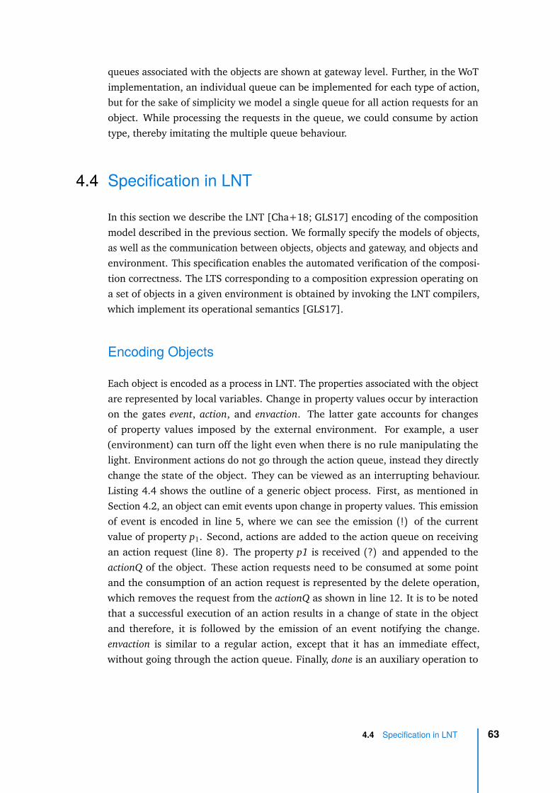
queues associated with the objects are shown at gateway level. Further, in the WoTimplementation, an individual queue can be implemented for each type of action,but for the sake of simplicity we model a single queue for all action requests for anobject. While processing the requests in the queue, we could consume by actiontype, thereby imitating the multiple queue behaviour.
4.4 Specification in LNT
In this section we describe the LNT [Cha+18; GLS17] encoding of the compositionmodel described in the previous section. We formally specify the models of objects,as well as the communication between objects, objects and gateway, and objects andenvironment. This specification enables the automated verification of the composi-tion correctness. The LTS corresponding to a composition expression operating ona set of objects in a given environment is obtained by invoking the LNT compilers,which implement its operational semantics [GLS17].
Encoding Objects
Each object is encoded as a process in LNT. The properties associated with the objectare represented by local variables. Change in property values occur by interactionon the gates event, action, and envaction. The latter gate accounts for changesof property values imposed by the external environment. For example, a user(environment) can turn off the light even when there is no rule manipulating thelight. Environment actions do not go through the action queue, instead they directlychange the state of the object. They can be viewed as an interrupting behaviour.Listing 4.4 shows the outline of a generic object process. First, as mentioned inSection 4.2, an object can emit events upon change in property values. This emissionof event is encoded in line 5, where we can see the emission (!) of the currentvalue of property p1. Second, actions are added to the action queue on receivingan action request (line 8). The property p1 is received (?) and appended to theactionQ of the object. These action requests need to be consumed at some pointand the consumption of an action request is represented by the delete operation,which removes the request from the actionQ as shown in line 12. It is to be notedthat a successful execution of an action results in a change of state in the objectand therefore, it is followed by the emission of an event notifying the change.envaction is similar to a regular action, except that it has an immediate effect,without going through the action queue. Finally, done is an auxiliary operation to
4.4 Specification in LNT 63

track one complete execution of the application scenario. By default, a compositionis designed to run infinitely (unbounded) and presence of done label helps to trackthe completion of one execution of the composition expression. All these operationsare modelled as a choice using the select operator. The entire process is enclosed ina loop to reproduce the reactive behaviour of the objects.
1 process OBJECT [ event , ac t ion , envact ion : any] i s2 var actionQ :QUEUE, p1 : bool , p1Val : bool , p2 : nat , p3 : . . .3 loop4 se l ec t5 event ( !o1 , ?any RuleId , !p1 , ?any bool ) [] event ( . . . ) [] . . .6 []7 ac t ion ( !o1 , ?any RuleId , ?p1Val ) ;8 actionQ := append ( p1Val , actionQ ) [] . . .9 []
10 p1Val := get_p1_value_fromQ ( actionQ ) ;11 p1 := p1Val ;12 actionQ := delete_p1_value_fromQ ( p1Val , act ionQ ) [] . .13 []14 envact ion ( !o1 , ?p1)15 []16 done17 end se lec t18 end loop19 end var20 end process
Listing 4.4: Outline of the LNT process of an IoT object
Now, let us look at a concrete device model. In Figure 4.5, the motion sensordevice used in Rule 2 of the retirement home scenario described in Listing 4.3 isshown. Motion sensor has a property on which is of boolean type in the WoT ThingDescription and when a motion is detected, the value of the property is set to true.Line 9 encodes the emit event. elem encapsulates the property on and its value and?any bool is used for synchronisation with rules. Lines 12-15 describe an action beingpushed to the action queue, and lines 18-27 encode the consumption of an actionfrom the queue. Since a single queue is used for all the different types of actions, ahelper function queue_has_property is used to pick the first corresponding action tobe consumed from the list of different actions in the queue (here, a single type ofaction, concerning property on, is possible). Finally, as in case of a motion sensor, aperson moving in the room can trigger the action of setting the motion property to
64 Chapter 4 A Formal Model for the Web of Things

true. This behaviour is accommodated in the LNT process by receiving the actionsfrom the environment, as described in lines 30-38.
1 (* motion s e n s o r d e v i c e model *)2 process motion [ motionevent : any , mot ionact ion : any ,
motionenvact ion : any , done : any] i s3 var q :QUEUE, motionon : bool , element :QELEMENT,
hasProper ty : bool in4 motionon := fa l se ; q := n i l ;5 element := elem (on , f a l se ) ;6 loop7 se l ec t8 (* emit e v en t *)9 motionevent ( !motion , !elem (on , motionon ) , ?any bool )
10 []11 (* push to a c t i o n queue *)12 var elementAct ion :QELEMENT in13 motionact ion ( !motion , ? elementAct ion of QELEMENT) ;14 q := append ( elementAction , q)15 end var16 []17 (* consume ev en t from a c t i o n queue *)18 eval hasProper ty := queue_has_property (on , q , ! ? element ) ;19 i f hasProper ty then20 case element in21 var onvalue : bool in22 elem (on , onvalue ) −>23 motionon := onvalue24 | any −> null25 end case ;26 q := de l e t e ( element , q)27 end i f28 []29 (* handle a c t i o n va lue from environment *)30 var elementAct ion :QELEMENT in31 motionenvact ion ( !motion , ? elementAct ion of QELEMENT) ;32 case elementAct ion in33 var onvalue : bool in34 elem (on , onvalue ) −>35 motionon := onvalue36 | any −> null37 end case38 end var39 []
4.4 Specification in LNT 65

40 (* used to t r a c k one comple t e e x e c u t i o n o f the compos i t i one x p r e s s i o n *)
41 i f empty (q) then42 done43 end i f44 end se lec t45 end loop46 end var47 end process
Listing 4.5: LNT process specifying a motion sensor
Encoding Rules
As with the encoding of the objects, rules are also encoded in an LNT process. TheECA rules of the format IF EVT THEN ACT are specified using the sequence (;)operator of LNT. Each rule is transformed into a process of the form EV T ; ACT ,where the select operator is used to encode the disjunction of events in EVT and thepar operator is used to encode the conjunction of events in EVT and actions in ACT,as shown below:
(* IF EVT1 OR EVT2 THEN ACT1 AND ACT2*)se l ec tEVT1 [] EVT2
end se lec t ;parACT1 || ACT2
end par
As a concrete example, the rule R2 in Listing 4.3 can be specified in LNT as follows:
1 (* IF s o f a _ p r e s e n c e _ d e t e c t e d −t rue THEN window_blinds−on *)2 process ru le2 [ event : any , a c t i on : any] i s3 event ( ! so fa , !r2 , !elem (on , true ) , ! t r u e ) ;4 ac t ion ( !window , !r2 , !elem ( bl inds , true ) )5 end process
Listing 4.6: LNT process specifying rule R2
66 Chapter 4 A Formal Model for the Web of Things

Here, sofa is the object identifier, r2 is the rule identifier and elem encapsulates thekey and value of the property. The suffix !true in event indicates that the rule is activewhen the event is triggered. This value can be either !true or !false, depending onthe execution state of the composition. In this case, initially the event emitted by thesofa appears with !true label and once the blinds are opened, R2 becomes inactiveand the event emitted by the sofa will be visible in the later parts of the LTS with a!false label.
Encoding Composition
The composition is encoded in a process. The patterns for transforming the composi-tion language operators to an LNT specification are shown in Table 4.3.
Operator Expression LNT Pattern
SEQUENCE C1 ; C2 C1 ; C2
PARALLEL C1 || C2 par C1 || C2 end par
CHOICE C1 + C2 select C1 [ ] C2 end select
REPEAT C1(k) i:=0; while i < k loop C1; i:=i+1 end loop
Tab. 4.3: Composition language to LNT transformation patterns
The sequence operator is specified using the sequential composition (;) operatorof LNT. Parallel execution is specified using the parallel composition (par), choiceis modelled using a nondeterministic choice (select), and bounded iteration isspecified using the cycle (loop) operator.
The composition described in the example can be encoded in a process as follows:
1 (* R1 ; (R2 || (R3 + R4) ) ; R5 *)2 process composit ion [ event : any , a c t i on : any , done : any] i s3 loop4 ru le1 [ event , a c t i on ] ;5 par6 ru le2 [ event , a c t i on ]7 ||
4.4 Specification in LNT 67
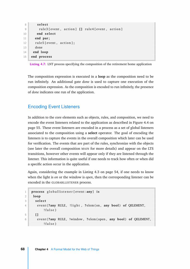
8 se l ec t9 ru le3 [ event , a c t i on ] [] ru le4 [ event , a c t i on ]
10 end se lec t11 end par ;12 ru le5 [ event , a c t i on ] ;13 done14 end loop15 end process
Listing 4.7: LNT process specifying the composition of the retirement home application
The composition expression is executed in a loop as the composition need to berun infinitely. An additional gate done is used to capture one execution of thecomposition expression. As the composition is encoded to run infinitely, the presenceof done indicates one run of the application.
Encoding Event Listeners
In addition to the core elements such as objects, rules, and composition, we need toencode the event listeners related to the application as described in Figure 4.4 onpage 55. These event listeners are encoded in a process as a set of global listenersassociated to the composition using a select operator. The goal of encoding thelisteners is to capture the events in the overall composition which later can be usedfor verification. The events that are part of the rules, synchronize with the objects(see later the overall composition MAIN for more details) and appear on the LTStransitions, however other events will appear only if they are listened through thelistener. This information is quite useful if one needs to track how often or when dida specific action occur in the application.
Again, considering the example in Listing 4.3 on page 54, if one needs to knowwhen the light is on or the window is open, then the corresponding listener can beencoded in the GLOBABLLISTENER process.
1 process g l o b a l l i s t e n e r [ event : any] i s2 loop3 se l ec t4 event ( ?any RULE , ! l i g h t , ?elem (on , any bool ) of QELEMENT,
! f a l s e )5 []6 event ( ?any RULE , !window , ?elem (open , any bool ) of QELEMENT,
! f a l s e )
68 Chapter 4 A Formal Model for the Web of Things
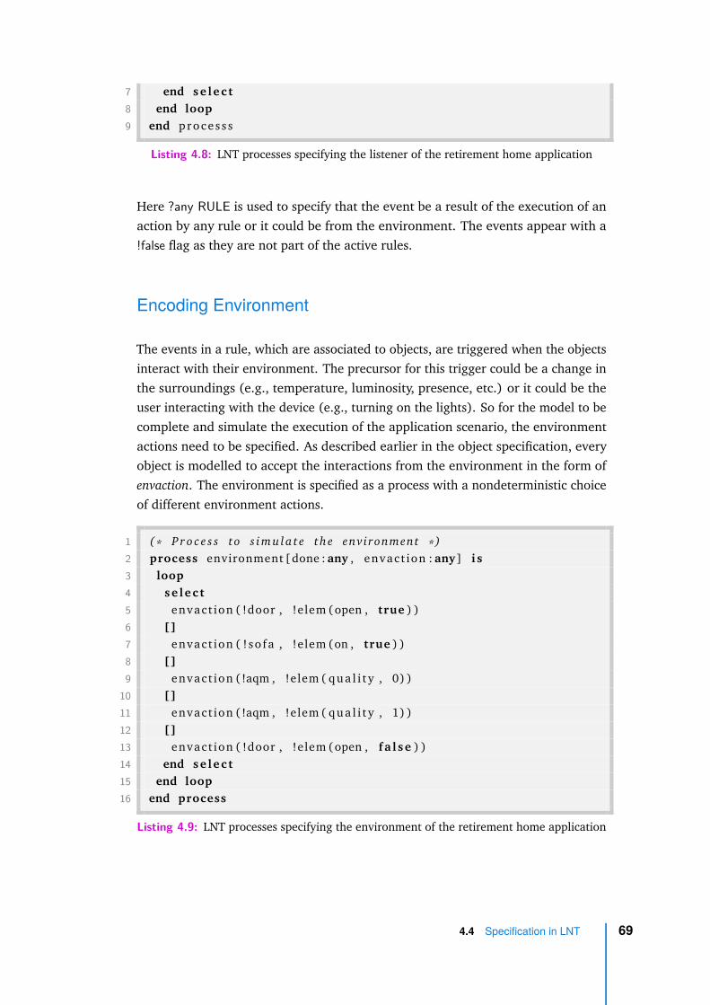
7 end se lec t8 end loop9 end proce s s s
Listing 4.8: LNT processes specifying the listener of the retirement home application
Here ?any RULE is used to specify that the event be a result of the execution of anaction by any rule or it could be from the environment. The events appear with a!false flag as they are not part of the active rules.
Encoding Environment
The events in a rule, which are associated to objects, are triggered when the objectsinteract with their environment. The precursor for this trigger could be a change inthe surroundings (e.g., temperature, luminosity, presence, etc.) or it could be theuser interacting with the device (e.g., turning on the lights). So for the model to becomplete and simulate the execution of the application scenario, the environmentactions need to be specified. As described earlier in the object specification, everyobject is modelled to accept the interactions from the environment in the form ofenvaction. The environment is specified as a process with a nondeterministic choiceof different environment actions.
1 (* P r o c e s s to s imu la t e the environment *)2 process environment [done : any , envact ion : any] i s3 loop4 se l ec t5 envact ion ( !door , !elem (open , true ) )6 []7 envact ion ( ! so fa , !elem (on , true ) )8 []9 envact ion ( !aqm , !elem ( qua l i t y , 0) )
10 []11 envact ion ( !aqm , !elem ( qua l i t y , 1) )12 []13 envact ion ( !door , !elem (open , f a l se ) )14 end se lec t15 end loop16 end process
Listing 4.9: LNT processes specifying the environment of the retirement home application
4.4 Specification in LNT 69
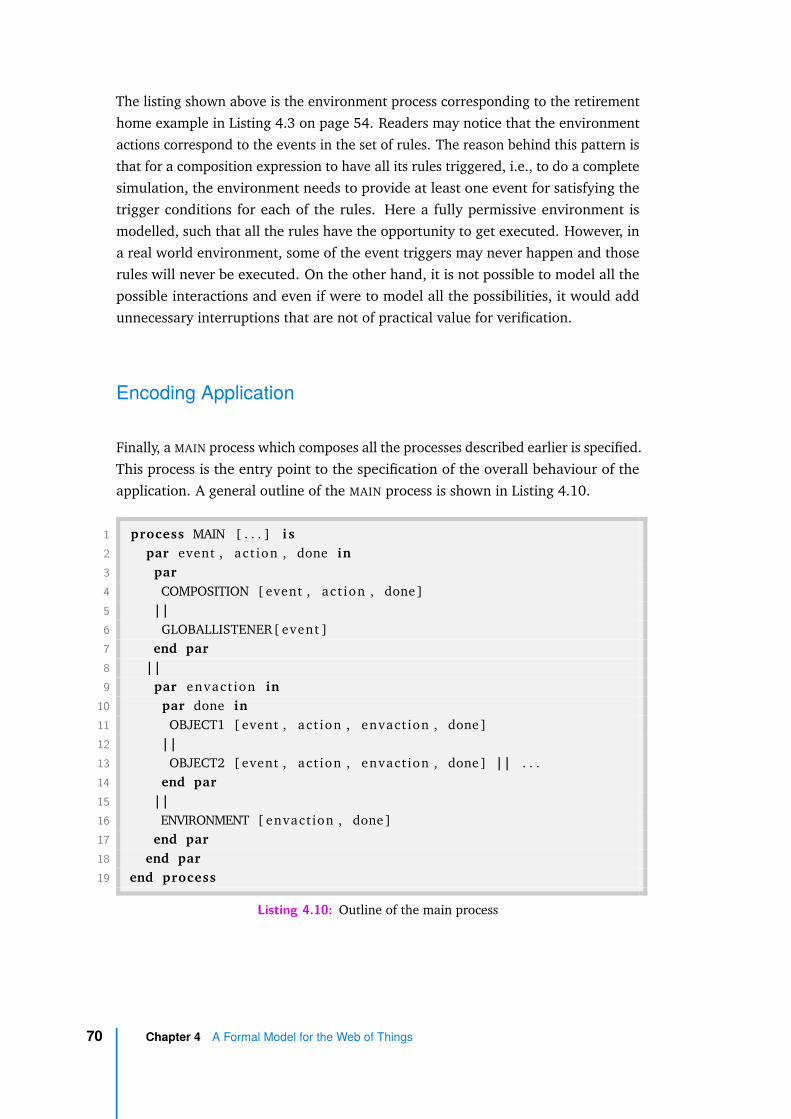
The listing shown above is the environment process corresponding to the retirementhome example in Listing 4.3 on page 54. Readers may notice that the environmentactions correspond to the events in the set of rules. The reason behind this pattern isthat for a composition expression to have all its rules triggered, i.e., to do a completesimulation, the environment needs to provide at least one event for satisfying thetrigger conditions for each of the rules. Here a fully permissive environment ismodelled, such that all the rules have the opportunity to get executed. However, ina real world environment, some of the event triggers may never happen and thoserules will never be executed. On the other hand, it is not possible to model all thepossible interactions and even if were to model all the possibilities, it would addunnecessary interruptions that are not of practical value for verification.
Encoding Application
Finally, a MAIN process which composes all the processes described earlier is specified.This process is the entry point to the specification of the overall behaviour of theapplication. A general outline of the MAIN process is shown in Listing 4.10.
1 process MAIN [ . . . ] i s2 par event , act ion , done in3 par4 COMPOSITION [ event , ac t ion , done]5 ||6 GLOBALLISTENER[ event ]7 end par8 ||9 par envact ion in
10 par done in11 OBJECT1 [ event , ac t ion , envact ion , done]12 ||13 OBJECT2 [ event , ac t ion , envact ion , done] || . . .14 end par15 ||16 ENVIRONMENT [ envact ion , done]17 end par18 end par19 end process
Listing 4.10: Outline of the main process
70 Chapter 4 A Formal Model for the Web of Things

The objects involved in the composition are interleaved and they do not synchronizeon events and actions, as they do not interact themselves directly in a gatewayintegration pattern. Synchronization on gate done is used to track the completion ofexecution and reset the execution status. The interaction among objects is done viathe COMPOSITION process. On the other hand, the environment interacts directly withthe objects and synchronises on the label envaction. By definition, the environmentcan change or interrupt at any time thereby preventing fair execution of rules. Inreal world though, the environment is more reasonable (e.g., temperature does notchange very often). So for simulation purposes we define the ENVIRONMENT with aset of relevant values identified by the property types and defined rules, instead ofall possible values. This also helps in reducing the state space of the overall systemand in fine-tuning the verification. The composition process COMPOSITION and theevent listener GLOBALLISTENER are interleaved as their behaviour is independent ofeach other. The combination of COMPOSITION and GLOBALLISTENER represents thegateway, which is in turn synchronised on events and actions with the behaviour ofthe objects and ENVIRONMENT. Effectively, COMPOSITION acts like an orchestrator,which dictates the activation of rules and the triggering of actions.
4.5 Specification in Maude
In order to support reconfiguration analysis, we encoded the objects and theircomposition in Maude. This specification allows us to perform rewriting analysis ofthe reconfiguration properties described in Chapter 5. We have chosen to build twodifferent encodings as they serve different purposes. The LNT encoding combinedwith the CADP toolbox allows us to verify the properties associated during the designof the application. The Maude encoding is specifically designed for reconfigurationanalysis. Maude is more suitable because reconfiguration analysis primarily involvestracking of state changes with respect to the original configuration and term rewritingespecially using equational logic, is an efficient way to perform these kinds of analysis.In this section we briefly introduce the different modules encoded in Maude as wehave covered all the particularities of the encoding in Section 4.4. Readers interestedin more details on the Maude specification may refer to the code online 1.
The Maude specification defines the objects, rules, composition, and the applica-tion. Listing 4.11 shows the Maude specification defining the LTS, object and thecomposition.
1https://github.com/ajaykrishna/mozart/tree/mozart/maude
4.5 Specification in Maude 71
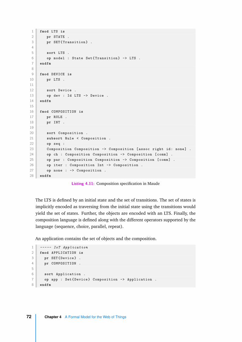
1 fmod LTS is2 pr STATE .3 pr SET{ Transition } .45 sort LTS .6 op model : State Set{ Transition } -> LTS .7 endfm89 fmod DEVICE is
10 pr LTS .1112 sort Device .13 op dev : Id LTS -> Device .14 endfm1516 fmod COMPOSITION is17 pr RULE .18 pr INT .1920 sort Composition .21 subsort Rule < Composition .22 op seq :23 Composition Composition -> Composition [assoc right id: none] .24 op ch : Composition Composition -> Composition [comm] .25 op par : Composition Composition -> Composition [comm] .26 op iter : Composition Int -> Composition .27 op none : -> Composition .28 endfm
Listing 4.11: Composition specification in Maude
The LTS is defined by an initial state and the set of transitions. The set of states isimplicitly encoded as traversing from the initial state using the transitions wouldyield the set of states. Further, the objects are encoded with an LTS. Finally, thecomposition language is defined along with the different operators supported by thelanguage (sequence, choice, parallel, repeat).
An application contains the set of objects and the composition.
1 ----- IoT Application2 fmod APPLICATION is3 pr SET{ Device } .4 pr COMPOSITION .56 sort Application .7 op app : Set{ Device } Composition -> Application .8 endfm
72 Chapter 4 A Formal Model for the Web of Things

Further, a rule is encoded as combination of two modules, one representing theevents and the other representing the actions, as shown in Listing 4.12.
1 ----- Rule2 fmod RULE is3 pr LRULE .4 pr RRULE .56 sort Rule .7 op rule : LRule RRule -> Rule .8 endfm9
10 ----- Left Rule11 fmod LRULE is12 pr REVENT .13 pr SET{ REvent } .1415 sort LRule .16 subsort REvent < LRule .17 op and : Set{ REvent } -> LRule [ctor] .18 op or : Set{ REvent } -> LRule [ctor] .19 endfm2021 ----- Right Rule22 fmod RRULE is23 pr RACTION .24 pr SET{ RAction } .2526 sort RRule .27 subsort RAction < RRule .28 op and : Set{ RAction } -> RRule [ctor] .29 endfm
Listing 4.12: Rule specification in Maude
Two different modules are used for encoding the rule, as the events support con-junction and disjunction of events, whereas the actions support the conjunction ofactions in the composition language.
Further, the execution semantics are defined using equational logic, which is notcovered here as we have already specified the operational semantics and its encodingin LNT in the previous section.
4.5 Specification in Maude 73
4.6 Concluding Remarks
In this chapter, we have described the WoT specification with emphasis on the WoTArchitecture and Thing Description (TD) specifications. The behaviour model forobjects defined in terms of an LTS is based on the TD specification. IoT applica-tions interact with each other through the gateway. These applications are builtby composing ECA rules using the composition language. We have defined theoperational semantics of the composition execution and it has been encoded as LNTand Maude specifications. In the next chapter, we look at the properties related todesign verification and reconfiguration analysis. These properties are verified on thespecifications of the application described in this chapter.
74 Chapter 4 A Formal Model for the Web of Things

Property Specification for theWeb of Things
5
„Automation may be a good thing, but don’tforget that it began with Frankenstein.
— An anonymous machine
In this chapter we specify the properties that can be checked on the IoT applicationsat two different phases of their lifecycle. The first part of the chapter deals withbehavioural properties that allow one to verify the correctness of an IoT applicationat design phase. The second part describes properties related to reconfiguration thatone can use to qualitatively compare the composition of the deployed applicationwith an updated composition while re-designing the application. The properties thatcan be checked during the design phase are specified in Model Checking Language(MCL). These properties are interpreted on the LTSs generated by compiling theLNT specification of the application. The reconfiguration properties are specified inMaude and they are interpreted on the Maude encoding of the application. Theseproperties also enable users to deploy the redesigned application in a consistentstate.
5.1 Design-time Verification with MCL
Here we describe several properties that are verified at design time using modelchecking techniques. These properties express both functional and quantitativeaspects of the designed application.
Properties are specified using the Model Checking Language (MCL) [MT08; MR18], adata-handling temporal language equipped with the Evaluator model checker [MT08;MR18; MS03] of CADP. This verification enables to identify incorrect behaviour andalso to perform qualitative and quantitative analysis of the IoT application at designtime.
75

As described in Chapter 4, by encoding in LNT an application consisting of objectsand a composition expression C, we automatically derive the LTS representing itsbehaviour (denoted by LTSC) using the CADP compilers. Properties are expressedin terms of the events and actions labelling the transitions of LTSC . Event labelshave the form EVENT !R !O !ELEM (k, v) !B, where R is the rule identifier, O isthe object identifier, and ELEM is a structure holding the object property (k,v). TheBoolean clause B serves to track whether the rule R is active in the compositionwhen the event is detected. Actions invoked by the rules are represented by labelsACTION !R !O !ELEM (k, v) and actions invoked by the environment are representedby labels ENVACTION !O !ELEM (k, v), which do not have a rule identifier sincethey are invoked independently of any rule.
5.1.1 Generic Properties
Generic properties are applicable to all IoT applications independently of the waythey are composed. These properties can be expressed using generic MCL patternsirrespective of the labels in LTSC .
Deadlock freedom
This classic property ensures that no rule of the composition expression is blockedfrom completing its execution. This property is useful in identifying missing depen-dencies that prevent the composition expression for executing successfully.
Low-end IoT sensors and actuators have a simple looping (“flower pattern”) be-haviour, where they constantly sense the environment or perform an actuation(update state attribute values). So, if we compose an application with only thesekinds of objects, the resulting behaviour will not encounter deadlocks, as at anypoint in time an interaction with the environment is possible when a fully permissiveenvironment is modelled. However, if we consider more complex objects, especiallythose involving a software, this may have an order of execution in their behaviour.Thus, when a composition is built using these objects and their order is not respected,it will lead to deadlocking behaviour.
A deadlock in terms of the LTS is a state from which a transition to another state isnot possible (sink state) and in terms of ECA rules, it indicates that it is impossible toexecute a certain event or action in an ECA rule of the composition. This impossiblecircumstance arises when the event or action requires another event or action to
76 Chapter 5 Property Specification for the Web of Things
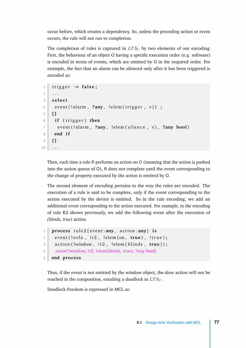
occur before, which creates a dependency. So, unless the preceding action or eventoccurs, the rule will not run to completion.
The completion of rules is captured in LTSC by two elements of our encoding.First, the behaviour of an object O having a specific execution order (e.g. software)is encoded in terms of events, which are emitted by O in the required order. Forexample, the fact that an alarm can be silenced only after it has been triggered isencoded as:
1 t r i g g e r := fa l se ;2 . . .3 se l ec t4 event ( !alarm , ?any , !elem ( t r i g g e r , v ) ) ;5 []6 i f ( t r i g g e r ) then7 event ( !alarm , ?any , !elem ( s i l ence , v ) , ?any bool )8 end i f9 []
10 . . .
Then, each time a rule R performs an action on O (meaning that the action is pushedinto the action queue of O), R does not complete until the event corresponding tothe change of property executed by the action is emitted by O.
The second element of encoding pertains to the way the rules are encoded. Theexecution of a rule is said to be complete, only if the event corresponding to theaction executed by the device is emitted. So in the rule encoding, we add anadditional event corresponding to the action executed. For example, in the encodingof rule R2 shown previously, we add the following event after the execution of(blinds, true) action.
1 process ru le2 [ event : any , a c t i on : any] i s2 event ( ! so fa , !r2 , !elem (on , true ) , ! t r u e ) ;3 ac t ion ( !window , !r2 , !elem ( bl inds , true ) ) ;4 event(!window, !r2, !elem(blinds, true), ?any bool)5 end process
Thus, if the event is not emitted by the window object, the done action will not bereached in the composition, entailing a deadlock in LTSC .
Deadlock freedom is expressed in MCL as:
5.1 Design-time Verification with MCL 77
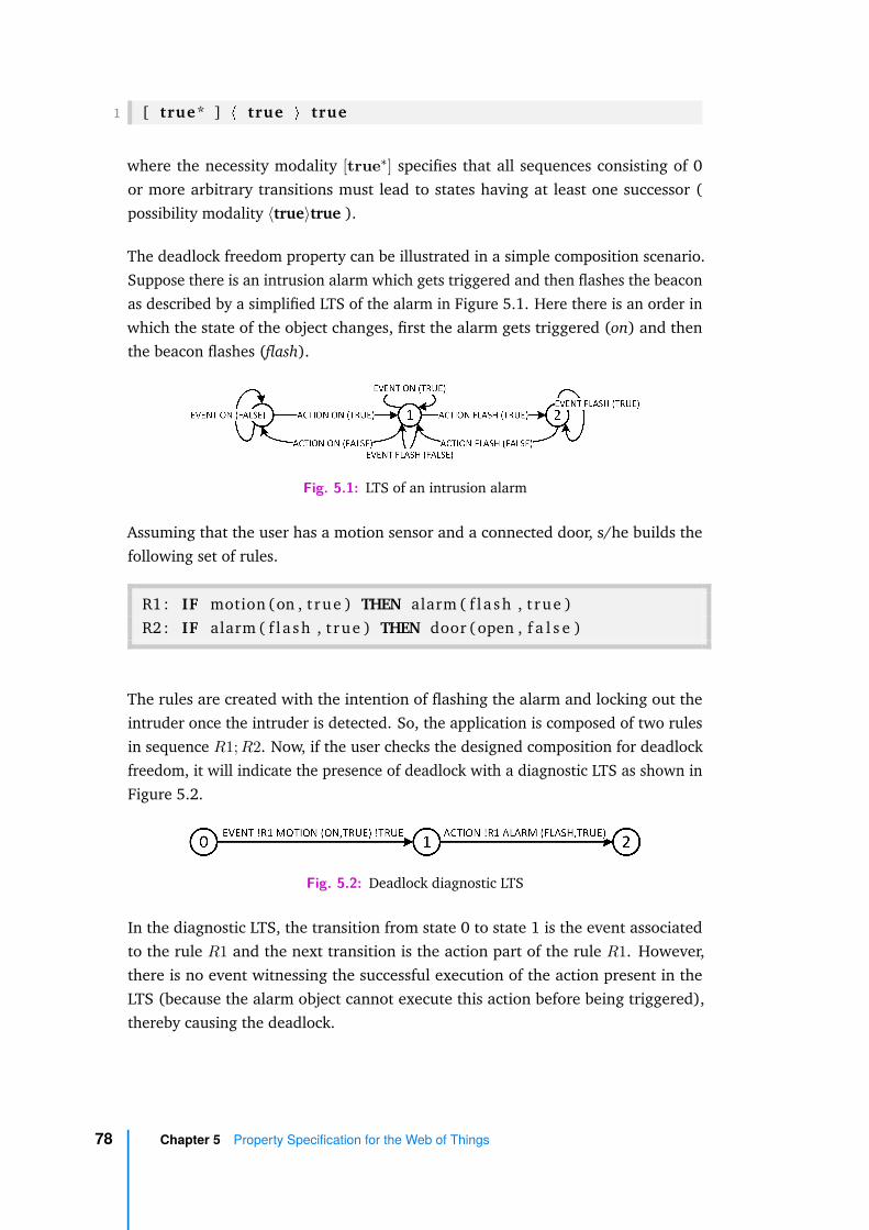
1 [ true* ] < true > true
where the necessity modality [true∗] specifies that all sequences consisting of 0or more arbitrary transitions must lead to states having at least one successor (possibility modality ⟨true⟩true ).
The deadlock freedom property can be illustrated in a simple composition scenario.Suppose there is an intrusion alarm which gets triggered and then flashes the beaconas described by a simplified LTS of the alarm in Figure 5.1. Here there is an order inwhich the state of the object changes, first the alarm gets triggered (on) and thenthe beacon flashes (flash).
Fig. 5.1: LTS of an intrusion alarm
Assuming that the user has a motion sensor and a connected door, s/he builds thefollowing set of rules.
R1 : IF motion (on , t rue ) THEN alarm ( f l a sh , t rue )R2 : IF alarm ( f l a sh , t rue ) THEN door (open , f a l s e )
The rules are created with the intention of flashing the alarm and locking out theintruder once the intruder is detected. So, the application is composed of two rulesin sequence R1; R2. Now, if the user checks the designed composition for deadlockfreedom, it will indicate the presence of deadlock with a diagnostic LTS as shown inFigure 5.2.
Fig. 5.2: Deadlock diagnostic LTS
In the diagnostic LTS, the transition from state 0 to state 1 is the event associatedto the rule R1 and the next transition is the action part of the rule R1. However,there is no event witnessing the successful execution of the action present in theLTS (because the alarm object cannot execute this action before being triggered),thereby causing the deadlock.
78 Chapter 5 Property Specification for the Web of Things

Completeness
Complementary to deadlock freedom, this property indicates that all actions of therules specified in a composition are reachable during the execution of the application.As the composition grows with a large number of rules, it is possible that someactions may never be executed and this property helps to identify such rules.
The successful execution of an action that assigns a new value v to a property k of anobject O is denoted by a subsequent event emitted by O with the updated value v ofproperty k. This can be ensured by checking, for each action ACTION !R !O !ELEM(k, v) encountered in the LTSC , that afterwards, as long as the corresponding eventEVENT !R !O !ELEM (k,v) was not executed, it is still possible to reach it:
1 [ true* . {ACTION !R !O ?ELEM_k_v : Str ing } .2 ( not {EVENT !R !O ! ELEM_k_v ?any})* ]3 < true* . {EVENT !R !O ! ELEM_k_v ?any} > true
where the field ELEM (k, v) is captured (as a string named ELEM_k_v) in the{ACTION...} label predicate and reused in the {EVENT...} predicate. Note thatwe check for emission of an event, instead of an action label. Since each actionis pushed into a queue and an event is emitted upon consumption of the action,checking for the corresponding event validates that the action has been executedsuccessfully.
Ideally, one would expect that the event is reached inevitably after the occurrence ofthe action. However, since we model an all permissive environment, this can preventthe reachability of the event (e.g., by continuously interrupting the processing of theactions from the action queue of an object). Therefore, in the property above weuse fair reachability [QS83], which skips the possible unfair cycles of environmentactions present in LTSC before the desired event. This reasonably reflects thepractical situations, in which the environment (e.g., users, weather conditions,daylight, etc.) acts in a much slower way than the objects.
Further, since we model a permissive environment, the unreachable actions refer tothe actions that are not triggered in spite of the events provided by the environment.This property can also be used to check, given a restricted environment, the actionsthat are not executed.
5.1 Design-time Verification with MCL 79

Spurious Events
Events are being continuously emitted by the devices indicating their current state.As the execution of the composition expression progresses, relevant rules are enabledand disabled. When a rule is enabled, the event being listened to appears with !trueflag, otherwise it appears with !false flag. Only the events that are part of the rulesappear in LTSC . An event that continuously appears in LTSC with !false flag isspurious, meaning that it is listened to, but never consumed by a rule.
Consider an event eventi emitting the current value v of a property k of an object O.This event is spurious if it occurs with !false flag on a cycle of LTSC that containsat least one action actionj not concerning property k of object O (meaning that theglobal execution of the composition expression progresses), but no other actionactioni that could have caused the event eventi. In other words, the action precursorof the event is missing on the cycle. This can be expressed in MCL as follows:
1 < true* . {EVENT ?any ?O ?K ?V ?any}>2 < ( not {ACTION ?any !O !K ?any})* .3 {ACTION ?any ?O2 ?K2 ?any where (O2 <> O) or (K2 <> K) } .4 ( not {ACTION ?any !O !K ?any})* . {EVENT ?any !O !K !V !
f a l se }5 > @
Fig. 5.3: Spurious event in an application
The first diamond modality specifies the existence of a finite sequence leading tothe event eventi. The action predicate extracts the fields O, k, and v contained inthe transition label for later use. The infinite looping modality (<...>@) extends thissequence with a cycle containing eventi and having the form described above. Ifthis formula holds on LTSC , the model checker will produce a lasso-shaped witnessas illustrated in Figure 5.3.
80 Chapter 5 Property Specification for the Web of Things

The case of spurious events is specific to the gateway implementation, these eventsappear on the LTS because they have the associated listeners on the gateway, butthe events are not relevant in the specific context of execution of the composition.
5.1.2 Application Properties
Application specific properties are expressed as temporal formulas containing labelsfrom LTSC . These properties are dependent on the application under considerationand one has to write specific temporal logic formulas to express the properties,unlike in generic properties where a standard formula is sufficient to verify theproperty across all IoT applications.
Functional Properties
The broad categories of functional properties are safety and liveness properties.Safety properties check that nothing bad happens in the system. Liveness propertiescheck that something good eventually happens.
Safety Property
Consider the retirement home example in Listing 4.3 on page 54, since an old-agepensioner lives in this house he might forget to turn off the HVAC when he is away.Safety properties are designed to specify these kind of situations. They check thatsomething unsafe never happens.
Safety properties ensure that there is no reachable error or unsafe state in the LTS.So a way to express safety properties is to forbid the undesirable execution sequencesin the LTS. Safety properties follow the pattern [SEQ]false, where SEQ denotesthe undesired sequence of actions, where the necessity modality followed by falseprohibits the occurrence of the sequence. A safety property in case of pensionerwould be that the HVAC is never turned on when the door is closed (pensioner isaway). This implies that in LTSC , once the door is closed, the HVAC should not beon in the subsequent states. This can be expressed in MCL as follows:
1 [ ( not DONE) * . ’EVENT !DOOR !ELEM (OPEN, FALSE) ! FALSE ’ .2 ( not DONE) * . ’EVENT !HVAC !ELEM (ON, TRUE) ! FALSE ’ ] fa l se
5.1 Design-time Verification with MCL 81

Here, (not DONE) is used to check for the sequence within one execution instance ofthe composition expression. Since the expression is executed infinitely, it is possiblethat events may appear in the subsequent execution instances with different values.The first event is the closing of the door (by setting open attribute to false) and thesecond event is the HVAC being in on state. The presence of this sequence of eventsis forbidden as specified by the false state formula after the necessity modality.
Liveness Property
Liveness properties assert that the specified behaviour eventually occurs in thesystem. Unlike a safety property, where the violation results in a diagnostic traceidentifying the violating sequence, the liveness property violation may not lead to afinite diagnostic trace as the action might eventually occur. So the way to expressliveness properties is by specifying the desired execution sequences. These propertiesfollow the pattern ⟨SEQ⟩true, where SEQ denotes the required sequence of actionswith possibility modality and true specify the existence of the sequence.
In the retirement home example in Listing 4.3 on page 54, a liveness property wouldbe to check that eventually the door would be closed. This can be expressed in MCLas follows:
1 <true* . ( not DONE) * . ’EVENT !DOOR !ELEM (ON, TRUE) ! FALSE ’ > true
Here true* specifies any arbitrary sequence of actions, followed by the closing ofthe door.
It can be observed that the spurious events property follows the liveness propertypattern. It in fact validates progress, whether the event will be eventually picked upby the the gateway.
Quantitative Properties
Quantitative properties are the characteristics of a system that can be observed andmeasured in terms of numerical values. They involve numerical measures such asprobabilities (e.g., probability of a bulb failing), time (e.g., time to transmit thevideo), resources (e.g., amount of battery used by the device), etc. It is possible todenote a property in terms of more than one measure. In our work, we specificallyconsider the probability for property verification.
82 Chapter 5 Property Specification for the Web of Things

The probability of executing an action in a composition can be computed to performcomparative analysis. Users can design different compositions, associate costs toactions and check for the probability of execution of an action across differentdesigns to optimise the costs.
The probability of execution of an action is computed using the support providedby the Evaluator5 tool of CADP [MR18]. Evaluator5 supports on-the-fly verificationof probabilistic properties on probabilistic transition systems (PTSs) [LS91], i.e.,LTSs with probabilities attached to transitions. Given a probability of occurrenceof an event, the probability of occurrence of an action is computed using the probkeyword in MCL, as shown in the formula below:
1 prob2 ( not DONE) * . {ACTION !R !O !ELEM(k , v ) } i s >=? 03 end prob
For instance, in the retirement home scenario in Listing 4.3 on page 54, turning onthe HVAC system is an expensive operation (in terms of power consumption). Theprobability of execution of this action (considering that all transitions in LTSC areequiprobable) is 0.497. However, if the parallel (∥) operation in the composition isreplaced by choice (+), the probability of turning on the HVAC reduces to 0.348.This will save energy but it actually changes the composition wherein the existingbehaviour is not preserved in the new composition. These kinds of changes canbe analysed through the reconfiguration properties that we describe in the nextsection.
In the computation, we considered all other transitions to be equiprobable, but wecould also define specific probabilities to events and compute the probability ofoccurrence of an action. It is to be noted that since the composition expression canrun infinitely, the probability of execution of an action will eventually aggregateto 1.0. Therefore, for probability analysis we need to consider the execution spaceof one instance of execution. Further, there are instances where a compositionexpression (structure) cannot be modified even if it does not seem cost-effectiveafter quantitative analysis. In such cases, one may think of replacing the objects withsimilar behaviour by more cost effective ones (e.g., replace halogen bulbs with LEDbulbs to be more energy efficient). In the next section, we define reconfigurationproperties that help one to compare the new application with the old application interms of their behaviour.
5.1 Design-time Verification with MCL 83
5.2 Reconfiguration Properties
IoT application are not designed once and for all. They are constantly changingas the needs of the user evolve. The evolution may involve replacing objects orenhancing an application with additional automation and while doing so, user maywant to better understand the effect of the evolution of an application. In broadsense, users may want to know if the existing services are preserved in the newapplication, whether there would be an interruption in the service while upgradingto the new application, whether the newly configured objects are really usefulcompared to previous object etc. These aspects of the evolution can be checkedby specifying reconfiguration properties. These properties can be checked by theuser to make the choice of whether to proceed with the deployment of the newapplication.
The reconfiguration properties compare two compositions, the composition that iscurrently deployed and the reconfigured version of the deployed composition. Areconfiguration may involve adding or replacing objects, rules, and modificationsto the composition expression. The comparison takes as input, the current andnew compositions and also the global state of the current application before thereconfiguration is applied. Global state contains the current state of all objects andthe state of execution of the composition expression. The comparison checks if thereconfiguration satisfies three reconfiguration properties: seamless, conservative,and impactful reconfiguration. These properties allow one to know whether thenew application can be deployed in a consistent state without having to completelyrestart the current application based on the global state of the application at thetime of the reconfiguration.
5.2.1 Seamless Reconfiguration
The global state of the application corresponds to the current state of objects and thecomposition expression. The seamless reconfiguration property checks the feasibilityof reaching this state in the newly configured application. This notion is importantbecause if the current global state is reachable in the new configuration, it meansthat the new application can be deployed without restarting the application fromthe beginning. Thus, from the perspective of a user, the deployment is seamless asthe current state of objects is maintained in the new configuration.
Let us now look at how the notion of seamless reconfiguration can be used todeploy the newly configured application. A user can reconfigure the application by
84 Chapter 5 Property Specification for the Web of Things
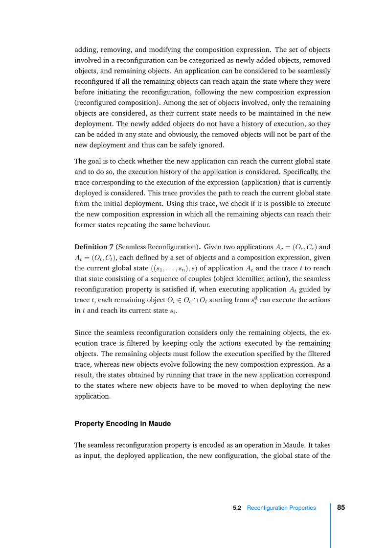
adding, removing, and modifying the composition expression. The set of objectsinvolved in a reconfiguration can be categorized as newly added objects, removedobjects, and remaining objects. An application can be considered to be seamlesslyreconfigured if all the remaining objects can reach again the state where they werebefore initiating the reconfiguration, following the new composition expression(reconfigured composition). Among the set of objects involved, only the remainingobjects are considered, as their current state needs to be maintained in the newdeployment. The newly added objects do not have a history of execution, so theycan be added in any state and obviously, the removed objects will not be part of thenew deployment and thus can be safely ignored.
The goal is to check whether the new application can reach the current global stateand to do so, the execution history of the application is considered. Specifically, thetrace corresponding to the execution of the expression (application) that is currentlydeployed is considered. This trace provides the path to reach the current global statefrom the initial deployment. Using this trace, we check if it is possible to executethe new composition expression in which all the remaining objects can reach theirformer states repeating the same behaviour.
Definition 7 (Seamless Reconfiguration). Given two applications Ac = (Oc, Cc) andAt = (Ot, Ct), each defined by a set of objects and a composition expression, giventhe current global state ((s1, . . . , sn), s) of application Ac and the trace t to reachthat state consisting of a sequence of couples (object identifier, action), the seamlessreconfiguration property is satisfied if, when executing application At guided bytrace t, each remaining object Oi ∈ Oc ∩ Ot starting from s0
i can execute the actionsin t and reach its current state si.
Since the seamless reconfiguration considers only the remaining objects, the ex-ecution trace is filtered by keeping only the actions executed by the remainingobjects. The remaining objects must follow the execution specified by the filteredtrace, whereas new objects evolve following the new composition expression. As aresult, the states obtained by running that trace in the new application correspondto the states where new objects have to be moved to when deploying the newapplication.
Property Encoding in Maude
The seamless reconfiguration property is encoded as an operation in Maude. It takesas input, the deployed application, the new configuration, the global state of the
5.2 Reconfiguration Properties 85
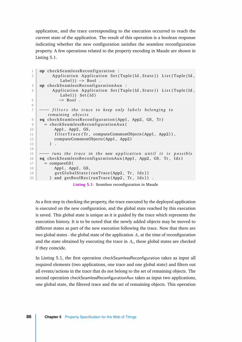
application, and the trace corresponding to the execution occurred to reach thecurrent state of the application. The result of this operation is a boolean responseindicating whether the new configuration satisfies the seamless reconfigurationproperty. A few operations related to the property encoding in Maude are shown inListing 5.1.
1 op checkSeamlessReconf igurat ion :2 App l i ca t i on App l i c a t i on Set { Tuple { Id , S ta te }} L i s t { Tuple { Id ,
Label }} −> Bool .3 op checkSeamlessReconf igurat ionAux :4 App l i ca t i on App l i c a t i on Set { Tuple { Id , S ta te }} L i s t { Tuple { Id ,
Label }} Set { Id }5 −> Bool .67 −−−− f i l t e r s the t r a c e to keep only l a b e l s b e l ong ing to
remaining o b j e c t s8 eq checkSeamlessReconf igurat ion (App1 , App2 , GS , Tr )9 = checkSeamlessReconf igurat ionAux (
10 App1 , App2 , GS ,11 f i l t e r T r a c e ( Tr , computeCommonObjects (App1 , App2) ) ,12 computeCommonObjects (App1 , App2)13 ) .1415 −−−− runs the t r a c e in the new a p p l i c a t i o n u n t i l i t i s p o s s i b l e16 eq checkSeamlessReconf igurat ionAux (App1 , App2 , GS , Tr , Ids )17 = compareGS(18 App1 , App2 , GS ,19 ge tG loba lS ta te ( runTrace (App2 , Tr , Ids ) )20 ) and getBoolRes ( runTrace (App2 , Tr , Ids ) ) .
Listing 5.1: Seamless reconfiguration in Maude
As a first step in checking the property, the trace executed by the deployed applicationis executed on the new configuration, and the global state reached by this executionis saved. This global state is unique as it is guided by the trace which represents theexecution history. It is to be noted that the newly added objects may be moved todifferent states as part of the new execution following the trace. Now that there aretwo global states - the global state of the application Ac at the time of reconfigurationand the state obtained by executing the trace in At, these global states are checkedif they coincide.
In Listing 5.1, the first operation checkSeamlessReconfiguration takes as input allrequired elements (two applications, one trace and one global state) and filters outall events/actions in the trace that do not belong to the set of remaining objects. Thesecond operation checkSeamlessReconfigurationAux takes as input two applications,one global state, the filtered trace and the set of remaining objects. This operation
86 Chapter 5 Property Specification for the Web of Things
calls runTrace to execute the second application guiding this execution by the trace.If an object is not available anymore (removed in the second application), anyobject can be run instead (yet according to the new composition expression). Theoperation compareGS checks that the remaining objects have reached the same statein both global states. The operation runTrace also returns a Boolean value indicatingwhether the complete trace was executed for remaining objects.
5.2.2 Conservative Reconfiguration
Conservative reconfiguration builds upon the seamless reconfiguration propertywhere it checks if the partial behaviour of the current application is replicable inthe new configuration. A reconfiguration is called conservative if the seamlessproperty is preserved and if, from the global state in which the reconfiguration isapplied, all behaviours that could be executed in the current application (objectsand composition expression) are still executable in the new application. It impliesthat all the possible executions in the current application from the global state arealso possible in the new configuration from its behaviourally equivalent global state.More precisely, each trace possible in current configuration is also possible in thenew configuration from their global states.
The conservative property is useful when one extends an existing composition byadding new services, but at the same time one wants to ensure that existing servicesare preserved in the new configuration.
Definition 8 (Conservative Reconfiguration). Given two applications Ac = (Oc, Cc)and At = (Ot, Ct), given the current global state ((s1, . . . , sn), s) of application Ac
and the trace t to reach that state, the conservative reconfiguration property issatisfied if the seamless reconfiguration property is satisfied and if each trace t′ thatcan be executed in Ac from (s1, . . . , sn) can also be executed in At from (s′
1, . . . , s′m)
where the global state (s′1, . . . , s′
m) is obtained by executing At guided by t.
The reconfiguration check involves two operations. First, the trace is executedon the new configuration and a global state of the new configuration is obtained.This needs to be done as the new configuration may have some objects replacedor removed and the global state of the current application cannot be mapped tothe new configuration. So an equivalent global state is obtained by replaying theexecution of events and actions that occurred in the current configuration on the newconfiguration. The newly added objects may have to be placed in appropriate states
5.2 Reconfiguration Properties 87

following the new composition expression. From this starting newly computed globalstate, the possible traces are computed to check for conservative reconfiguration.
Property Encoding in Maude
Similar to seamless reconfiguration, the check takes as input the deployed appli-cation, the new configuration, along with the global state and the execution trace.Therefore, the operations for checking conservative reconfiguration extend the seam-less reconfiguration operations. The result of the check is a boolean value indicatingwhether the property is satisfied.
1 op checkConserva t iveReconf igura t ion :2 App l i ca t i on App l i c a t i on Set { Tuple { Id , S ta te }} L i s t { Tuple { Id ,
Label }}3 −> Bool .45 eq checkConserva t iveReconf igura t ion (app ( Devs1 , Compo1) , app( Devs2
, Compo2) , GS1 , Tr )6 = compareFutureTraces (7 Devs1 , Compo1 , GS1 ,8 g e t B u f f e r s ( runTrace ( app( Devs1 , Compo1) , Tr , keepA l l Id s (
Devs1 ) ) ) ,9 Devs2 , Compo2 ,
10 ge tG loba lS ta te (11 runTrace (12 app( Devs2 , Compo2) ,13 f i l t e r T r a c e ( Tr ,14 computeCommonObjects ( app( Devs1 , Compo1) , app ( Devs2
, Compo2) ) ) ,15 computeCommonObjects ( app( Devs1 , Compo1) , app ( Devs2 ,
Compo2) )16 ) ) ,17 g e t B u f f e r s (18 runTrace (19 app( Devs2 , Compo2) ,20 f i l t e r T r a c e ( Tr ,21 computeCommonObjects ( app( Devs1 , Compo1) , app ( Devs2
, Compo2) ) ) ,22 computeCommonObjects ( app( Devs1 , Compo1) , app ( Devs2 ,
Compo2) ) ) )23 ) .
Listing 5.2: Conservative property in Maude
The check first computes the equivalent global state. Then all the possible executiontraces from the computed global state are matched with the execution traces fromthe current configuration. The match process runs until a mismatch is found or until
88 Chapter 5 Property Specification for the Web of Things
all the traces are matched (complete match). The Maude code shown in Listing 5.2shows how the comparison is executed. The equivalent global state is computed byrunning the trace on the new composition expression. Further, getBuffers get thestate of all action queues. Finally, the operation compareFutureTraces executes allpossible traces in the current application, and checks whether traces can be executedon the original application as well.
5.2.3 Impactful Reconfiguration
Impactful reconfiguration extends the seamless property with an additional con-straint. A reconfiguration is called impactful if the seamless property is preserved andif all new behaviours can be executed in the new composition. It checks whether thenewly added behaviours can be executed given the current state of the application.
The check proceeds by executing the trace to obtain the global state of the newapplication. Then, all the behaviours that are reachable from the global state arecomputed following the new composition expression. This set of behaviours mustcontain all the newly added behaviours for the reconfiguration to be impactful.
Here the term impactful is used because all the newly added behaviours make animpact on the execution of the composition expression. This property is useful if onewants to measure the usefulness of the newly added behaviour.
Definition 9 (Impactful Reconfiguration). Given two applications Ac = (Oc, Cc) andAt = (Ot, Ct), given the current global state ((s1, . . . , sn), s) of application Ac andthe trace t to reach that state, the impactful reconfiguration property is satisfied ifthe seamless reconfiguration property is satisfied and if each new object Oi ∈ Ot\Oc
has its entire behaviour covered in Tr ∪ Tr′ (i.e., for each Oi, for each s1ed−→ s2 ∈ Ti,
e appears at least once in Tr ∪ Tr′), where (s′1, . . . , s′
m) is the global state obtainedby executing At guided by t, Tr is the set of all traces that can be executed in At toreach (s′
1, . . . , s′m), and Tr′ is the set of all traces that can be executed in At from
(s′1, . . . , s′
m).
It is worth comparing this property with the completeness property written inMCL. Both the properties check for reachability but in impactful reconfigurationa comparison between two compositions is made whereas in the completenessproperty reachability in a single composition is checked. Both properties have someoverlapping elements.
5.2 Reconfiguration Properties 89

Property Encoding in Maude
The impactful property checks that all new behaviours can be executed in the new ap-plication. The Maude code for checking the property is partially shown in Listing 5.3.The property check involves first checking seamless property where the global stateof the new composition is deduced from the trace of the current application. Thesecond part of the check focuses solely on the new composition. Following the newcomposition expression, all the observable events and actions associated with eachof the devices are computed and stored. Finally, the getExecutions operation checksthat all events are reachable in the objects from their respective initial states.
1 op check Impac t fu lReconf igura t ion : App l i ca t i on App l i c a t i on L i s t {Tuple { Id , Label }} −> Bool .
23 eq check Impac t fu lReconf igura t ion (App1 , app( Devs2 , Compo2) , Tr )4 = . . . ,5 getExecut ions ( runTrace (6 app( Devs2 , Compo2) ,7 f i l t e r T r a c e ( Tr ,
computeCommonObjects (App1 , app( Devs2 , Compo2) ) ) ,
8 computeCommonObjects (App1 , app(Devs2 , Compo2) )
9 ) )10 )11 ) .
Listing 5.3: Impactful property in Maude
The two properties, impactful and conservative reconfiguration, have seamless prop-erty embedded within them. The precondition of having the seamless property tobe satisfied exists because without the reachability of the global state in the newcomposition, the impactful and conservative properties do not make sense. Thenotion of global state in the new composition is the binding link between the currentand the proposed reconfiguration. Further, the impactful and conservative proper-ties are independent of each other. A reconfiguration that preserves conservativereconfiguration may not satisfy the impactful reconfiguration property because still,it may not be possible to reach all new events in the new expression.
90 Chapter 5 Property Specification for the Web of Things

5.2.4 Reconfiguration Example
The reconfiguration properties can be illustrated using a set of applications describedin Figure 5.4. The figure shows three different compositions. An original one andtwo more reconfigurations built on the original configuration.
Fig. 5.4: Compositions illustrating reconfiguration
Initially, an application was designed using a single rule and it was deployed as anapplication. The rule uses two objects, a motion sensor and a light. The light offersa single event/action where it can be turned on (it turns off automatically after awhile). The automation was deployed at the entrance of a home where whenever amotion was detected, the light was turned on.
In the first reconfiguration of this application, another motion sensor is broughtin and is placed to capture the exit. Along with this, the light was replaced byanother light which could be turned off and turned on at will. Now the automationinvolved two rules composed in a sequence. First, when the motion is detected atthe entrance the light is turned on and when the motion is detected at the exit, thelight is turned off. Unfortunately, after some time the light bulb fails and it is being
5.2 Reconfiguration Properties 91

replaced by another light which supports changing of its colours. The behaviourof objects involved in the compositions is shown in Figure 5.4. It abstracts certaindetails but provides important information about the order of execution.
As readers may recall that seamless reconfiguration concerns the remaining objectsand it checks whether these objects can reach their original states in the new applica-tion following the trace. In this reconfiguration, the remaining objects in composition2 and composition 3 are the motion sensors (motion sensor 1 in composition 2 andboth the sensors in composition 3) which have a single state which is reachable atany time in the composition. The first reconfiguration, when compared with theoriginal application, returns negative for conservative reconfiguration. It is becausethe behaviour of turning on the light at any instant is not preserved anymore inthe new application. The change however is impactful, as the new behaviours canbe executed from any state. The change from composition 2 to composition 3 onthe other hand is conservative, as the same behaviour is preserved but since thenew behaviour (changing of colour) cannot be executed following the compositionexpression, the reconfiguration is not impactful.
5.3 Concluding Remarks
In this section, we have described two different sets of properties: one focusingon verification during the initial design of the application and the second set ofproperties that can be checked during the redesign of the application. The use oftwo different encodings is due to the verification requirements. Even though boththe checks happen during the (re)design of the application, they are associated withdifferent phases of an application lifecycle. LNT and MCL encoding based on processalgebra is useful when checking the behavioural correctness of a system. Rewritinglogic in Maude on the other hand offers a more efficient way to track the evolutionof states, which is the essence of reconfiguration.
92 Chapter 5 Property Specification for the Web of Things

Mozart Tool 6„Users do not care about what is inside the box,
as long as the box does what they need done.
— Jef Raskinabout Human Computer Interfaces
This chapter describes the implementation of the proposals mentioned in the previouschapters. The MOZART tool is developed considering non-expert home users. Thistool is developed on top of the Mozilla WebThings components. Later in the chapter,we present some of the usability and verification related experiments.
6.1 Project WebThings
WebThings is a project by Mozilla which implements the Web of Things architecture.The objective of the set of tools provided by the project is to enable end-usersto monitor and control IoT devices over the web. Mozilla WebThings Gatewayand WebThings Framework are the two major software distributions provided byMozilla under this initiative. An incentive for implementing our proposals on top ofthis project was that it is hosted under Mozilla Public License 2.0, which permitsextensions and modifications.
6.1.1 WebThings Gateway
WebThings Gateway is a software that can be deployed on smart home gateways. Itallows users to monitor and control the IoT devices installed in their homes throughthe web interface provided by the gateway. Compared to the software that is usuallyprovided by the device manufacturers, the gateway allows one to manage the deviceslocally. The data is stored locally and not processed through cloud services. Anadded advantage is that users do not have to install multiple software for differentdevices. The gateway acts as an IoT Hub for all the devices in a home where they
93

can be managed via a web browser. The gateway can be installed on a Raspberry Pi,or it can be hosted on a PC or as a docker image.
Fig. 6.1: WebThings monitoring UI
The UI component of the gateway called ThingsUI, provides a web user interfacethat allows users to connect the smart home devices and create rules using theseobjects to build automation scenarios. Figure 6.1 shows the monitoring screenof the ThingsUI. It shows a set of IoT objects and also virtual objects that can becontrolled through the UI. Virtual objects are a software implementation of real-world objects. They can be primarily used for testing of automation scenarios asthey can be monitored and controlled just like the real objects. Figure 6.2 shows theECA rule automation UI provided by the Things UI. It shows a rule which detectsthe temperature of the room using a Philips Hue sensor and if the temperature isgreater than 30, it turns on a light to red. Users create these rules by dragging anddropping the objects that are available on the bottom of the screen and by settingtheir attributes as events and actions. A rules engine implemented in the gatewayexecutes these rules. It is worth noting that when users create multiple rules, theyare executed as and when the event conditions are satisfied, without any specificorder.
94 Chapter 6 Mozart Tool
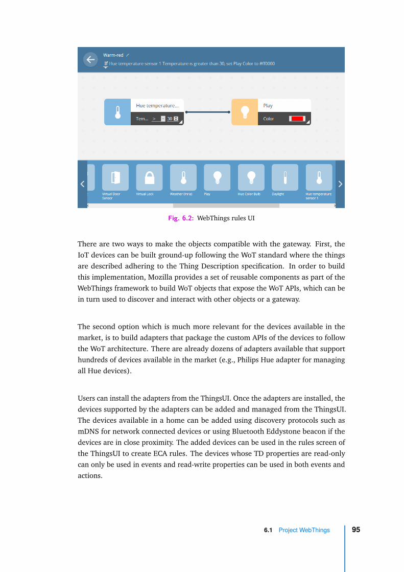
Fig. 6.2: WebThings rules UI
There are two ways to make the objects compatible with the gateway. First, theIoT devices can be built ground-up following the WoT standard where the thingsare described adhering to the Thing Description specification. In order to buildthis implementation, Mozilla provides a set of reusable components as part of theWebThings framework to build WoT objects that expose the WoT APIs, which can bein turn used to discover and interact with other objects or a gateway.
The second option which is much more relevant for the devices available in themarket, is to build adapters that package the custom APIs of the devices to followthe WoT architecture. There are already dozens of adapters available that supporthundreds of devices available in the market (e.g., Philips Hue adapter for managingall Hue devices).
Users can install the adapters from the ThingsUI. Once the adapters are installed, thedevices supported by the adapters can be added and managed from the ThingsUI.The devices available in a home can be added using discovery protocols such asmDNS for network connected devices or using Bluetooth Eddystone beacon if thedevices are in close proximity. The added devices can be used in the rules screen ofthe ThingsUI to create ECA rules. The devices whose TD properties are read-onlycan only be used in events and read-write properties can be used in both events andactions.
6.1 Project WebThings 95

6.2 WebThings Extensions for Design-time Verificationand Reconfiguration
The extensions to Things gateway were identified by gathering the feature require-ments. The following requirements were defined for the implementation of thetool:
• Users are to be provided with an interface to compose rules using the compo-sition language. Users can graphically build a composition and visualize theoverall application
• The interface should allow users to use the rules created by them using theRule UI. New rules can be created from the composition interface as well
• Once the composition is built, the interface should provide a way to verifytheir compositions. The verification process should be seamless to the userand the results of verification should be available on the same interface
• If the result of verification is not satisfactory, users can revise their compositionon the screen. Otherwise, they can proceed with the deployment of theapplication
• The UI should provide the option to deploy the composition. Deploymentshould kick-off the execution of the composition respecting the compositionlanguage semantics
• The UI should provide a screen to redesign an existing composition. The screenshould allow users not only to modify rules and their order of execution, butalso to create new rules
• The UI should allow users to compare the running composition with the newcomposition for reconfiguration properties. Just like the design verification,the process should be seamless to the users (e.g., click of a button)
• Once users are satisfied with the redesign of the composition, the tool shouldallow users to deploy the new composition with minimum interruption to therunning application (objects).
The last three items in the requirements relate to the reconfiguration and theremaining ones relate to the design time verification. Although all the extensionsare packaged within the MOZART tool and they re-use certain code, we describe
96 Chapter 6 Mozart Tool

the extensions in two sections as they serve conceptually two different analysis atdifferent stages of application lifecycle.
6.2.1 Design-time Verification Components
In the context of desing-time verification requirements we built three componentson top of the Thing gateway. A UI for end-users, a verification component, andan execution engine. Figure 6.3 shows an overview of the approach. Users cangraphically build the composition through a UI component. It is transformed intoa formal specification by the verification component. The specification is verifiedusing a verification toolbox and valid compositions are deployed using the executionengine. Now let us look at these components in detail:
Fig. 6.3: Mozart: Design and deployment of IoT applications
The UI component is developed keeping in mind that the learning curve for theusers is kept to minimum. The design principles of the ThingUI are carried over tothe UI for composing the rules. Figure 6.4 shows the UI for composition of the rules.Similar to the rules UI, users can drag-and-drop the rules and also the compositionoperators to build a composition. The drag-and-drop mechanism works like a jigsaw,users can drop a composition operator and then they can drop in the rules in theoperand slots of the operator. In this way, they can incrementally build a compositionexpression. In Figure 6.4, on the top half of the left column, the existing rules can
6.2 WebThings Extensions for Design-time Verification andReconfiguration
97
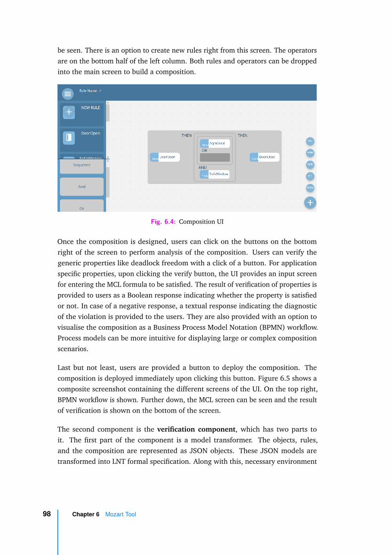
be seen. There is an option to create new rules right from this screen. The operatorsare on the bottom half of the left column. Both rules and operators can be droppedinto the main screen to build a composition.
Fig. 6.4: Composition UI
Once the composition is designed, users can click on the buttons on the bottomright of the screen to perform analysis of the composition. Users can verify thegeneric properties like deadlock freedom with a click of a button. For applicationspecific properties, upon clicking the verify button, the UI provides an input screenfor entering the MCL formula to be satisfied. The result of verification of properties isprovided to users as a Boolean response indicating whether the property is satisfiedor not. In case of a negative response, a textual response indicating the diagnosticof the violation is provided to the users. They are also provided with an option tovisualise the composition as a Business Process Model Notation (BPMN) workflow.Process models can be more intuitive for displaying large or complex compositionscenarios.
Last but not least, users are provided a button to deploy the composition. Thecomposition is deployed immediately upon clicking this button. Figure 6.5 shows acomposite screenshot containing the different screens of the UI. On the top right,BPMN workflow is shown. Further down, the MCL screen can be seen and the resultof verification is shown on the bottom of the screen.
The second component is the verification component, which has two parts toit. The first part of the component is a model transformer. The objects, rules,and the composition are represented as JSON objects. These JSON models aretransformed into LNT formal specification. Along with this, necessary environment
98 Chapter 6 Mozart Tool

Fig. 6.5: Mozart UI screenshots
is generated in the LNT specification to simulate the scenario execution. The secondpart is the software that integrates the Mozart tool with the CADP verificationtoolbox [Gar+13]. It invokes the compilation of the specification, the propertyverification, and returns the results of verification to the interface.
The final component is the execution engine, which takes care of the deployment ofthe application. The gateway provides a rule engine that can execute the rules andwe needed to build an execution engine that executes these rules in a specific orderfollowing the composition language semantics. As the composition expression canbe seen as a workflow, similar to execution of a workflow, the composition follows atoken-based execution. The rules in a composition having the token are consideredactive and remaining ones are inactive. Active rules are executed by the rule engine.Initially, all rules are considered to be inactive (disabled), then a set of rules areactivated (enabled) based on the composition expression.
6.2.2 Reconfiguration Components
Now let us take a look at the three components built on top of WebThings to supportchecking of reconfiguration properties and deployment of the new composition.
Support for reconfiguration is achieved by making extensions at three differentlevels. First, at the design level, interfaces need to be available to specify changes toan existing application. Once the changes are specified, a component to verify theconsistency and correctness of the redesign is required. Finally, deployment of thenew configuration needs to be taken care of.
6.2 WebThings Extensions for Design-time Verification andReconfiguration
99

Fig. 6.6: Reconfiguration workflow
The reconfiguration workflow is shown in Figure 6.6. Initially, users would havedesigned the application and deployed it in their homes. Once a reconfiguration ofthe running application is envisaged, users move the concerned application to thenewly designed reconfiguration UI. The UI is similar to the composition UI shown inFigure 6.2, except it imports the existing composition to this reconfiguration screen.Just like the composition UI, it allows users not only to modify the rules which mayinvolve adding, removing, or changing of objects but also to change the way inwhich the rules are composed in an application. Once the redesign is finalised, userscan compare the new configuration with the original configuration to check impactof reconfiguration. The comparison is guided by the reconfiguration properties tobe checked. The properties are checked by transforming the JSON specification ofthe composition into a specification in Maude using a model transformer. Uponfinishing the check, the users are provided with a response indicating if they couldproceed with the deployment. If the response is negative, they can revise the designor keep the application running as it is. Otherwise, they can proceed to the next stepwhere the reconfiguration manager handles the deployment.
The manager performs two tasks: i) undeploy the removed objects preserving thestate of remaining objects; ii) deploy the new objects and run the reconfiguredapplication, picking up from where it left off.
First, current states of all objects are stored in a database along with the executionhistory of the application. This is followed by disabling of rules. Finally, rules arereplaced or new rules are created depending on the reconfiguration. New rules are
100 Chapter 6 Mozart Tool
created using the Rules UI and they can be enabled or disabled depending on thecomposition. Here, we mention rules and not individual objects because adding orremoving of objects is a modification to a rule, as objects are a part of an event oran action. In other words, adding an object means including the object in a rule,from the available pool of objects and removing an object implies it is no longerused in a rule. Now, these rules need to be deployed for the application to run.Deployment resumes the application from the state where it was before initiatingthe reconfiguration. Remaining objects maintain their previous states. For newlyadded objects, we run the execution trace of the former application on the newcomposition expression. As a result, we obtain the states where the new objectshave to be moved when deploying the new application. Newly added rules areinitialized in disabled state. As a last step, we use the execution history of theformer application to compute the state from where the new composition expressionshould start, which allows us to determine the set of rules to be enabled. Fromhere, previously developed execution engine takes care of the running of application.It follows the composition expression semantics by enabling or disabling relevantsubsets of rules as the execution of the expression progresses.
6.3 Technology and Implementation
A simplified view of the components and technologies used in the tool is shown inFigure 6.7. Mozilla WebThings Gateway is built on NodeJS. Our extension takesadvantage of the existing packages available in the platform to implement theexecution engine. Rules, the composition of rules, the state of objects, and executiontraces are stored in a file-based SQLite database. BPMN visualisation is handled usingbpmn.io JavaScript library. The backend transformation and verification componentis implemented as a Spring Boot application hosted on an embedded Tomcat server.The transformation from JSON to LNT and Maude specification is handled usingFreemarker templating engine. Communication with the CADP verification toolboxand Maude system is done via system calls.
6.3.1 CADP Toolbox
The CADP toolbox [Gar+13] which provides first class support for LNT as a specifi-cation language, contains a wide range of tools to perform formal verification tasks.Here are some of the tools that we used in our work. These tools can be invokedfrom the command-line.
6.3 Technology and Implementation 101
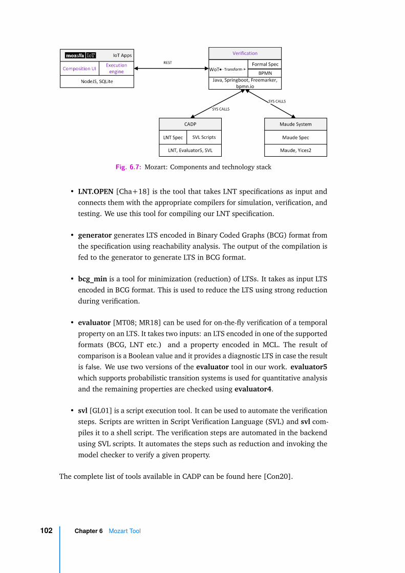
Fig. 6.7: Mozart: Components and technology stack
• LNT.OPEN [Cha+18] is the tool that takes LNT specifications as input andconnects them with the appropriate compilers for simulation, verification, andtesting. We use this tool for compiling our LNT specification.
• generator generates LTS encoded in Binary Coded Graphs (BCG) format fromthe specification using reachability analysis. The output of the compilation isfed to the generator to generate LTS in BCG format.
• bcg_min is a tool for minimization (reduction) of LTSs. It takes as input LTSencoded in BCG format. This is used to reduce the LTS using strong reductionduring verification.
• evaluator [MT08; MR18] can be used for on-the-fly verification of a temporalproperty on an LTS. It takes two inputs: an LTS encoded in one of the supportedformats (BCG, LNT etc.) and a property encoded in MCL. The result ofcomparison is a Boolean value and it provides a diagnostic LTS in case the resultis false. We use two versions of the evaluator tool in our work. evaluator5which supports probabilistic transition systems is used for quantitative analysisand the remaining properties are checked using evaluator4.
• svl [GL01] is a script execution tool. It can be used to automate the verificationsteps. Scripts are written in Script Verification Language (SVL) and svl com-piles it to a shell script. The verification steps are automated in the backendusing SVL scripts. It automates the steps such as reduction and invoking themodel checker to verify a given property.
The complete list of tools available in CADP can be found here [Con20].
102 Chapter 6 Mozart Tool

6.3.2 Maude System
Maude 3.0 tools can be installed on Linux systems. It comes with a connection to anSMT solver for satisfiability (SAT) analysis. In our work, we use Maude with Yices2 distribution, but there is an option to use CVC 4 for SAT solving. Maude systemis packaged as a executable, which takes as input the Maude specification. In thisspecification, we can specify the reconfiguration properties to be verified using rewkeyword followed by the name of the property. This initiates the rewriting analysisand returns the result on the terminal. The result of rewriting is a boolean responseindicating whether the property is satisfied or not, which is captured and displayedon the user screen.
6.3.3 Implementation
In this section we briefly describe some of the implementation details of the verifica-tion and execution engine components.
The objects, rules and composition expressions are encoded as JSON data. For eachof these data, a corresponding Freemarker template which generates LNT and Maudecode is defined. The template is defined with static elements in the specification likeprocess declaration in LNT, generic Maude operations etc. These elements remaincommon for every object, rule or composition. But there are specific elements likeidentifiers, labels to synchronise on, etc., and these are dynamically populated fromthe JSON data. Listing 6.1 shows a template to generate the Maude specificationof a scenario. A scenario is basically a composition of rules. The elements within< # . . . / > denote the loading of the objects into the memory and their values aredynamically loaded within $ . . . $. Here we can see that the rule identifiers and theircomposition are dynamically populated (lines 14-16).
1 load semant ics . maude2 <# l i s t maudescenario . ge tOb jec t s () as obj>3 load ${ obj }$ .maude4 </# l i s t>5
6 fmod SCENARIO i s7 pr DEVICE .8 pr QID .9 subsor t Qid < Id .
10 pr COMPOSITION .
6.3 Technology and Implementation 103
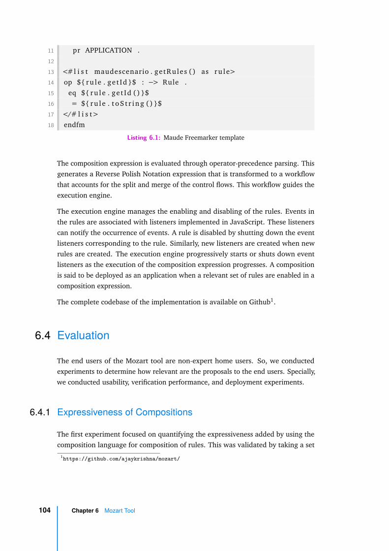
11 pr APPLICATION .12
13 <#l i s t maudescenario . getRules () as ru l e>14 op ${ ru l e . ge t Id }$ : −> Rule .15 eq ${ ru l e . ge t Id () }$16 = ${ ru l e . t o S t r i n g () }$17 </# l i s t>18 endfm
Listing 6.1: Maude Freemarker template
The composition expression is evaluated through operator-precedence parsing. Thisgenerates a Reverse Polish Notation expression that is transformed to a workflowthat accounts for the split and merge of the control flows. This workflow guides theexecution engine.
The execution engine manages the enabling and disabling of the rules. Events inthe rules are associated with listeners implemented in JavaScript. These listenerscan notify the occurrence of events. A rule is disabled by shutting down the eventlisteners corresponding to the rule. Similarly, new listeners are created when newrules are created. The execution engine progressively starts or shuts down eventlisteners as the execution of the composition expression progresses. A compositionis said to be deployed as an application when a relevant set of rules are enabled in acomposition expression.
The complete codebase of the implementation is available on Github1.
6.4 Evaluation
The end users of the Mozart tool are non-expert home users. So, we conductedexperiments to determine how relevant are the proposals to the end users. Specially,we conducted usability, verification performance, and deployment experiments.
6.4.1 Expressiveness of Compositions
The first experiment focused on quantifying the expressiveness added by using thecomposition language for composition of rules. This was validated by taking a set
1https://github.com/ajaykrishna/mozart/
104 Chapter 6 Mozart Tool
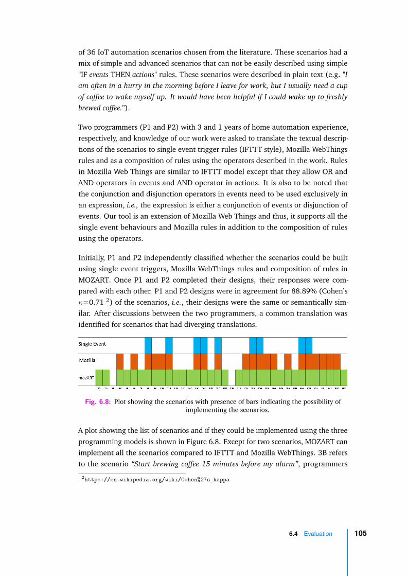
of 36 IoT automation scenarios chosen from the literature. These scenarios had amix of simple and advanced scenarios that can not be easily described using simple"IF events THEN actions" rules. These scenarios were described in plain text (e.g. "Iam often in a hurry in the morning before I leave for work, but I usually need a cupof coffee to wake myself up. It would have been helpful if I could wake up to freshlybrewed coffee.").
Two programmers (P1 and P2) with 3 and 1 years of home automation experience,respectively, and knowledge of our work were asked to translate the textual descrip-tions of the scenarios to single event trigger rules (IFTTT style), Mozilla WebThingsrules and as a composition of rules using the operators described in the work. Rulesin Mozilla Web Things are similar to IFTTT model except that they allow OR andAND operators in events and AND operator in actions. It is also to be noted thatthe conjunction and disjunction operators in events need to be used exclusively inan expression, i.e., the expression is either a conjunction of events or disjunction ofevents. Our tool is an extension of Mozilla Web Things and thus, it supports all thesingle event behaviours and Mozilla rules in addition to the composition of rulesusing the operators.
Initially, P1 and P2 independently classified whether the scenarios could be builtusing single event triggers, Mozilla WebThings rules and composition of rules inMOZART. Once P1 and P2 completed their designs, their responses were com-pared with each other. P1 and P2 designs were in agreement for 88.89% (Cohen’sκ=0.71 2) of the scenarios, i.e., their designs were the same or semantically sim-ilar. After discussions between the two programmers, a common translation wasidentified for scenarios that had diverging translations.
Fig. 6.8: Plot showing the scenarios with presence of bars indicating the possibility ofimplementing the scenarios.
A plot showing the list of scenarios and if they could be implemented using the threeprogramming models is shown in Figure 6.8. Except for two scenarios, MOZART canimplement all the scenarios compared to IFTTT and Mozilla WebThings. 3B refersto the scenario “Start brewing coffee 15 minutes before my alarm”, programmers
2https://en.wikipedia.org/wiki/Cohen%27s_kappa
6.4 Evaluation 105
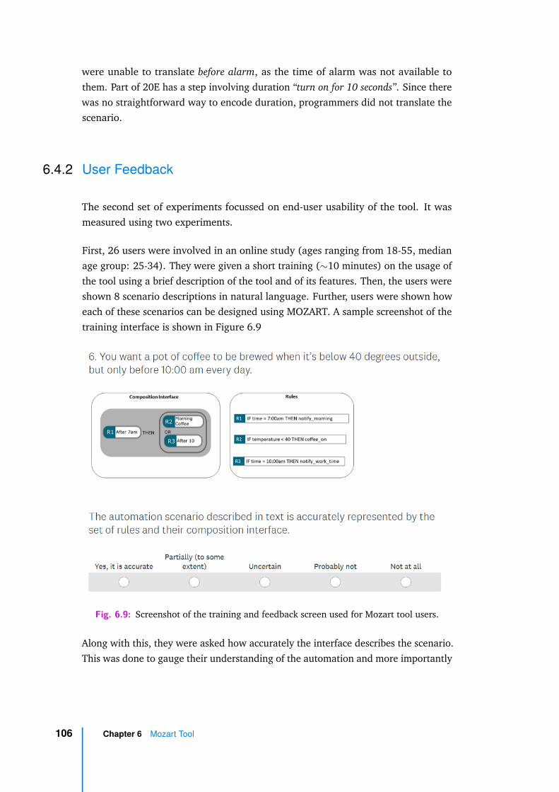
were unable to translate before alarm, as the time of alarm was not available tothem. Part of 20E has a step involving duration “turn on for 10 seconds”. Since therewas no straightforward way to encode duration, programmers did not translate thescenario.
6.4.2 User Feedback
The second set of experiments focussed on end-user usability of the tool. It wasmeasured using two experiments.
First, 26 users were involved in an online study (ages ranging from 18-55, medianage group: 25-34). They were given a short training (∼10 minutes) on the usage ofthe tool using a brief description of the tool and of its features. Then, the users wereshown 8 scenario descriptions in natural language. Further, users were shown howeach of these scenarios can be designed using MOZART. A sample screenshot of thetraining interface is shown in Figure 6.9
Fig. 6.9: Screenshot of the training and feedback screen used for Mozart tool users.
Along with this, they were asked how accurately the interface describes the scenario.This was done to gauge their understanding of the automation and more importantly
106 Chapter 6 Mozart Tool
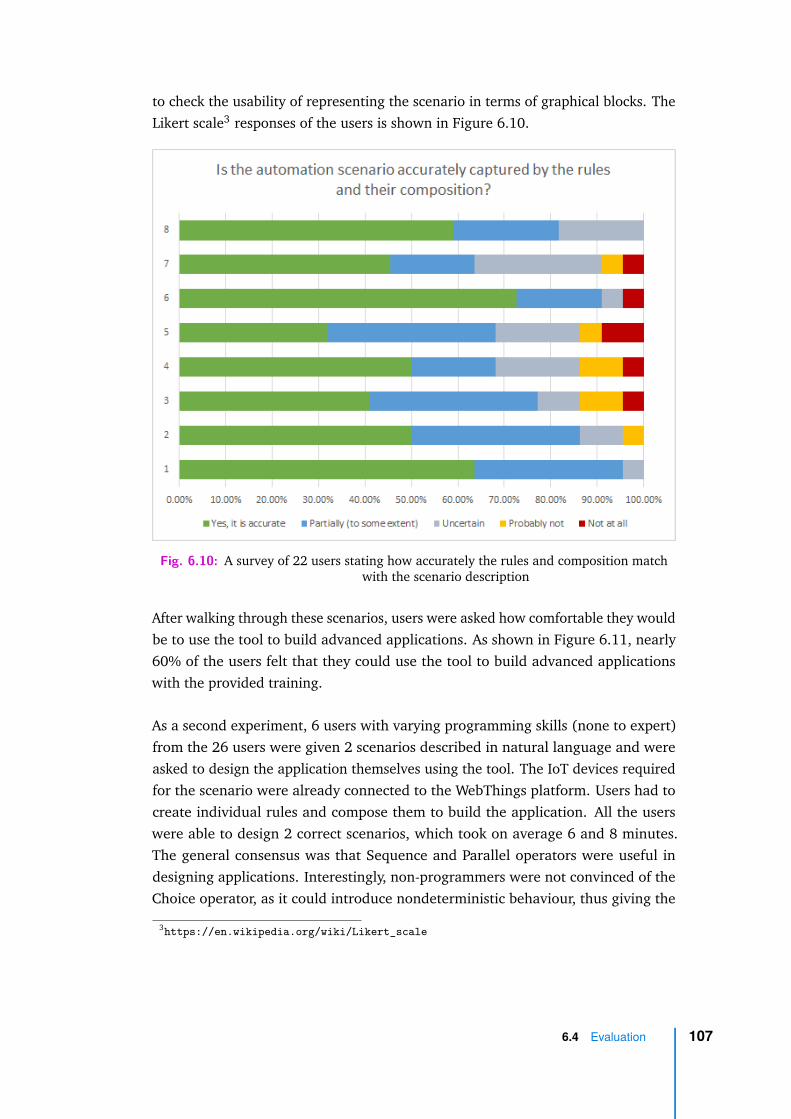
to check the usability of representing the scenario in terms of graphical blocks. TheLikert scale3 responses of the users is shown in Figure 6.10.
Fig. 6.10: A survey of 22 users stating how accurately the rules and composition matchwith the scenario description
After walking through these scenarios, users were asked how comfortable they wouldbe to use the tool to build advanced applications. As shown in Figure 6.11, nearly60% of the users felt that they could use the tool to build advanced applicationswith the provided training.
As a second experiment, 6 users with varying programming skills (none to expert)from the 26 users were given 2 scenarios described in natural language and wereasked to design the application themselves using the tool. The IoT devices requiredfor the scenario were already connected to the WebThings platform. Users had tocreate individual rules and compose them to build the application. All the userswere able to design 2 correct scenarios, which took on average 6 and 8 minutes.The general consensus was that Sequence and Parallel operators were useful indesigning applications. Interestingly, non-programmers were not convinced of theChoice operator, as it could introduce nondeterministic behaviour, thus giving the
3https://en.wikipedia.org/wiki/Likert_scale
6.4 Evaluation 107
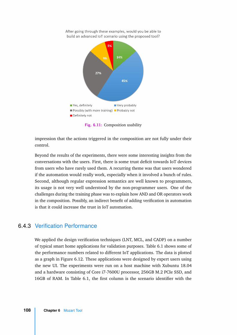
Fig. 6.11: Composition usability
impression that the actions triggered in the composition are not fully under theircontrol.
Beyond the results of the experiments, there were some interesting insights from theconversations with the users. First, there is some trust deficit towards IoT devicesfrom users who have rarely used them. A recurring theme was that users wonderedif the automation would really work, especially when it involved a bunch of rules.Second, although regular expression semantics are well known to programmers,its usage is not very well understood by the non-programmer users. One of thechallenges during the training phase was to explain how AND and OR operators workin the composition. Possibly, an indirect benefit of adding verification in automationis that it could increase the trust in IoT automation.
6.4.3 Verification Performance
We applied the design verification techniques (LNT, MCL, and CADP) on a numberof typical smart home applications for validation purposes. Table 6.1 shows some ofthe performance numbers related to different IoT applications. The data is plottedas a graph in Figure 6.12. These applications were designed by expert users usingthe new UI. The experiments were run on a host machine with Xubuntu 18.04and a hardware consisting of Core i7-7600U processor, 256GB M.2 PCIe SSD, and16GB of RAM. In Table 6.1, the first column is the scenario identifier with the
108 Chapter 6 Mozart Tool
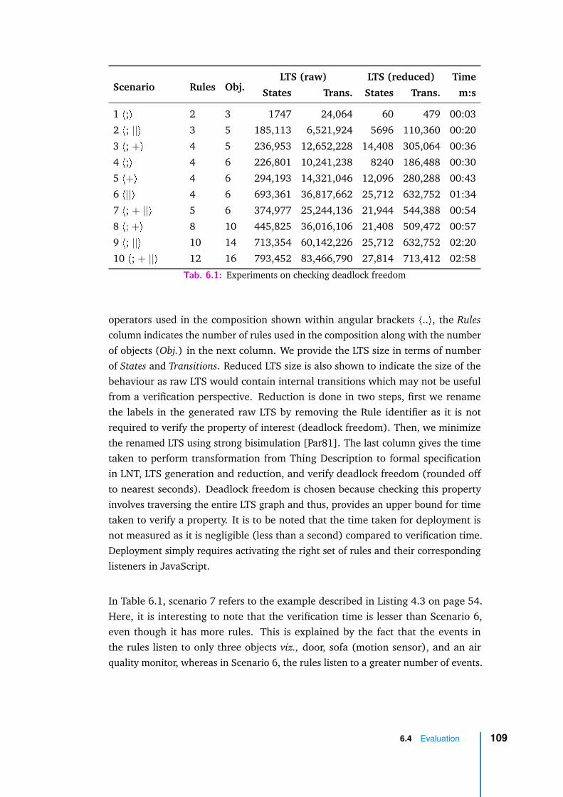
Scenario Rules Obj.LTS (raw) LTS (reduced) Time
States Trans. States Trans. m:s
1 <;> 2 3 1747 24,064 60 479 00:03
2 <; ||> 3 5 185,113 6,521,924 5696 110,360 00:20
3 <; +> 4 5 236,953 12,652,228 14,408 305,064 00:36
4 <;> 4 6 226,801 10,241,238 8240 186,488 00:30
5 <+> 4 6 294,193 14,321,046 12,096 280,288 00:43
6 <||> 4 6 693,361 36,817,662 25,712 632,752 01:34
7 <; + ||> 5 6 374,977 25,244,136 21,944 544,388 00:54
8 <; +> 8 10 445,825 36,016,106 21,408 509,472 00:57
9 <; ||> 10 14 713,354 60,142,226 25,712 632,752 02:20
10 <; + ||> 12 16 793,452 83,466,790 27,814 713,412 02:58
Tab. 6.1: Experiments on checking deadlock freedom
operators used in the composition shown within angular brackets <..>, the Rulescolumn indicates the number of rules used in the composition along with the numberof objects (Obj.) in the next column. We provide the LTS size in terms of numberof States and Transitions. Reduced LTS size is also shown to indicate the size of thebehaviour as raw LTS would contain internal transitions which may not be usefulfrom a verification perspective. Reduction is done in two steps, first we renamethe labels in the generated raw LTS by removing the Rule identifier as it is notrequired to verify the property of interest (deadlock freedom). Then, we minimizethe renamed LTS using strong bisimulation [Par81]. The last column gives the timetaken to perform transformation from Thing Description to formal specificationin LNT, LTS generation and reduction, and verify deadlock freedom (rounded offto nearest seconds). Deadlock freedom is chosen because checking this propertyinvolves traversing the entire LTS graph and thus, provides an upper bound for timetaken to verify a property. It is to be noted that the time taken for deployment isnot measured as it is negligible (less than a second) compared to verification time.Deployment simply requires activating the right set of rules and their correspondinglisteners in JavaScript.
In Table 6.1, scenario 7 refers to the example described in Listing 4.3 on page 54.Here, it is interesting to note that the verification time is lesser than Scenario 6,even though it has more rules. This is explained by the fact that the events inthe rules listen to only three objects viz., door, sofa (motion sensor), and an airquality monitor, whereas in Scenario 6, the rules listen to a greater number of events.
6.4 Evaluation 109

Fig. 6.12: Scenarios and verification Time
Scenario 10 with 12 rules and 16 objects is quite large for a single application, andit takes under 3 minutes to get the verification result. In practice though, whenwe considered the scenarios mentioned in the literature [HC15; Ur+14; Bri+17;MSC+19], they rarely required more than 8 rules. Our scenario with 8 rules took areasonable amount of time (less than a minute) for verification.
The performance of the reconfiguration analysis (Maude system) was measuredwith different redesigns. The reconfiguration analysis took a few milliseconds forthese applications. For instance, a quite large scenario with 6 rules and 10 objects,it took 6ms for the conservative check. This is explained by the fact that the checkdoes not execute the composition, enumerating all possible states like in the LNTencoding. Instead, it syntactically compares the traces from the global state. From auser perspective, considering that we are dealing with web applications, the resultsare almost instantaneous.
6.4.4 Deployment Setup
The tool was evaluated by implementing and deploying scenarios in a local environ-ment with IoT devices. The experiment setup hosted the MOZART tool on a RaspberryPi server. In the same network, a set of connected devices which included PhilipsHue lights, Hue Play bars, Hue motion sensor, luminosity sensor, thermometer, andconnected speakers were added to mimic a smart home. A configuration involving
110 Chapter 6 Mozart Tool

some of the objects is shown in Figure 6.13. These objects were used to build smarthome rules.
Fig. 6.13: Smart home setup for experiments
The set of rules were composed to build different compositions (some of them havebeen listed in Table 6.1 on page 109). In some scenarios, we substituted the deviceswith the devices we had, to mimic equivalent behaviour, otherwise we definedvirtual objects using the Mozilla API. For example, intrusion alarm was implementedthrough connected speakers. Further, these compositions were deployed and testedfor correct execution. The deployment was almost instantaneous as it just requiresactivation of JavaScript listeners. In case of real devices, the environment is thephysical environment and we introduced changes in the environment. In situationswhere it was impossible to modify the environment (e.g., humidity), we used theWoT APIs to set the values. We validated the deployment engine by verifying thedevices whether they followed the composition language semantics.
Once the deployment was validated, the deployed applications were reconfiguredusing the reconfiguration UI. Since the reconfiguration UI is a replica of the UI fordesigning the applications, we did not focus on the usability aspects of the interface.
6.4 Evaluation 111
Our earlier experiments indicated that users were able build scenarios using theproposed UI.
Finally, whenever seamless reconfiguration was possible, we deployed these appli-cations and verified that the reconfiguration manager works as expected, i.e., theexisting states of the devices remained consistent after deployment.
6.5 Discussion
In this chapter, we presented a tool for composition, deployment and reconfigurationof IoT applications. The tool implements our proposals and validates on real-worldapplications. The experiments indicate that the tool can be used by the targetedend-users. Regarding the design verification performance, scalability is a validconcern but since the verification happens at design time users will be more willingto spend time checking the composition rather than deploying it without checksand having problems during the execution. In contrast, the reconfiguration check isdone when an application is already running and therefore users may expect a quickresult. This is taken care by the Maude encoding which returns the results in a fewmilliseconds even for large compositions.
112 Chapter 6 Mozart Tool
Conclusion 7„The end of a melody is not its goal: but
nonetheless, had the melody not reached its endit would not have reached its goal either. Aparable.
— Friedrich NietzscheGerman philosopher
This thesis presents a work that leverages formal methods for the development ofIoT applications to ensure they will function as intended upon deployment. Thework presents a solution that not only supports the design to deployment of theapplications, but also their reconfiguration. Here we summarize the contributionsand take a look at the possible avenues for extending this work.
7.1 Models for the IoT
The first step in guaranteeing that the designed applications work as expected lies inknowing how the objects behave and how they interact with other objects and theenvironment. In this context, the work proposed a formal model that describes thebehaviour of the objects and their interactions.
The behaviour of the objects is specified in terms of a Labelled Transition System(LTS) which describes how and when the objects can interact with their surroundings.This model is based on the Web of Things (WoT) Thing Description (TD) specification,that is part of the WoT standards proposed by W3C. Unlike other textual andsemantic description of the objects, this model explicitly describes the internalbehaviour of the objects and their interfaces in a generic manner, i.e., the descriptionis not bound to any semantic schema. The model is derived from the TD to makethe approach relevant to a large number of devices. However, it can be based onany other standard describing the objects in IoT, provided the right transformationis in place.
113
In the behavioural model, the change of a state in an object is described in termsof events and actions to support Event-Condition-Action programming (ECA), alsoknown as Trigger-Action-Programming (TAP) rules. The ECA model was chosenbecause it is very popular in the smart home automation where an automationscenario (composition of objects) involves a rule in the form of IF-event-THEN-action.
Further, the work models IoT applications as a set of objects whose interactions aredefined by ECA rules. The interaction model is based on the Mozilla WoT specifi-cation, a concrete implementation complementary to the W3C’s WoT specification.Specifically, a gateway interaction pattern where the objects communicate through agateway is modelled.
The models of the objects and their composition are specified in two differentspecification languages. First, a specification in LNT is defined. LNT is a formalspecification language with process algebraic features which is the input of CADPtoolbox. This specification serves as the basis for verifying properties during theinitial design of the application. Another specification in Maude rewriting logic isdefined to support verification during the reconfiguration of a deployed IoT applica-tion. To the best our knowledge, our work is one of the first formal specificationsbased on the W3C’s WoT standard.
7.2 Verification for the IoT
The next step in establishing correctness of the designed application is by verifyingthat the application satisfies certain properties. The work identifies two sets ofproperties that can be checked on IoT applications: i) a set of properties thatcheck if the initial design of the application is satisfactory. ii) a set of properties toqualitatively compare a newly reconfigured design with the existing configuration ofthe application.
The properties that are checked during the initial design of the application can becategorized into generic and application properties. The generic properties identifiedare deadlock freedom, completeness, and detection of spurious events. IoT objectsbeing reactive and permissive, the notion of deadlock is not obvious, howeverupon close inspection of the behaviour of the objects especially ones with software,deadlocking situations are very much possible in an application. Verification of thesedeadlocks is achieved by a specific encoding of the objects and rules. Completenessproperties check the reachability of the rules in the composition expression. Spurious
114 Chapter 7 Conclusion
event detection is a property specific to the gateway interaction pattern. It tracksthe events that occur infinitely often but are never consumed.
The models can be verified for application specific properties, such as safety and live-ness properties. In addition to it, the probability of execution of events and actionsin a composition can be computed by describing the composition as a probabilistictransition system (i.e., decorating the LTS transitions with probabilities).
Unlike in an industrial automation, consumer IoT applications are not designedonce for all. Typically, the applications are redesigned more often than in theindustrial setup. To support such reconfigurations, our work identified three differentproperties that compare the behaviour of the existing application with the newapplication. These properties also indicate whether the new application can bedeployed seamlessly, without having to restart the entire application. Seamlessreconfiguration property checks whether the current state of the application isreachable in the newly redesigned application. Conservative reconfiguration propertychecks whether the current behaviour of the application is preserved in the newapplication. Impactful reconfiguration property focuses on the new applicationwhere it checks whether all the newly added features are reachable, i.e., to be ableto have an impact on the application.
It is worth noting that all the property verifications happen during the (re)designof the application and therefore the verification does not have to provide results innear real time.
7.3 Tool Implementation
The contributions mentioned above have been proposed with an end-user in mind.Therefore, we built a tool support to check the usability and applicability of thesesolutions.
Our MOZART tool was built by extending the Mozilla WebThings platform ratherthan building a new implementation, which enabled us to take advantage of thelarge number of devices already supported by the platform. In addition to thesupport provided by the WebThings for ECA rules, Mozart is backed by a compositionlanguage that allows one to easily compose rules in a graphical way. Our compositionlanguage enables to build more expressive automation scenarios.
The tool abstracts the formal verification from end-users by transforming the JSONcomposition to specifications in LNT and Maude. It integrates with the verification
7.3 Tool Implementation 115

tools provided by CADP and Maude to carry out formal analysis. Here the userinput is only required for the design of the composition, all the other steps beingautomated.
The tool support is provided not only for the design and verification but also forthe deployment and reconfiguration of the IoT applications. The deployment of theoriginal configuration and the reconfiguration uses an execution engine that followsthe composition language semantics. The states of the objects are manipulated usingthe WebThings API.
Usability related experiments indicate that the users find the tool useful and itrequires minimum training for users to learn the new extensions to the WebThingstool. Although, the primary objective of the tool support is to serve as a proof-of-concept implementation of proposals, it is found to be more expressive than existingUI-based ECA programming tools.
7.4 Future Work
The proposals made in this work have scope for improvements and extensions.Here we mention a few of them that we plan to do in the near-term, as well assome long-term projects. We have listed these works under three categories: i) theverification improvements that can be accomplished in the short to medium term, ii)quantitative analysis of WoT applications, and iii) proposals pertaining to the WoTimplementation and application domain.
Verification Improvements
There is an immediate scope for improving usability by providing application specificMCL formulas as a graphical input in form of patterns, for instance taking inspirationfrom the temporal property patterns proposed in [DAC98]. This is more user-friendlyas it eliminates the need for users to write the application specific properties in MCL.This would only require an extension at the user interface level.
Another area for improvement is the way the result of verification is presented to theend-user. Currently, we present the result of verification as a Boolean response witha textual description of the property violation in case of a false response. We couldinstead display the counterexample LTS to show the source of property violation.
116 Chapter 7 Conclusion

The next logical extension concerning formal analysis would be to present the usersthe solutions to overcome the property violations. The solutions can be in the formof suggestions to replace the devices in the composition or to modify the rules or thecomposition expression so that the composition complies with the property check.
Currently, we do not have mechanisms to inform users of possible feature inter-actions in the smart home setup. It would be useful if users are aware of theinteractions when they design a composition. This can be implemented using staticanalysis techniques where the interactions are automatically detected whenever thecomposition is modified in the interface [JGC05].
Concerning the fairness of execution with respect to the environment, we canelaborate further on correctness properties relying on classical fairness notions(weak, strong) [PP18] which can be used to identify whether the application canstill progress under an unfair environment. This could be useful as IoT applicationsare typically subject to ever changing environment.
Quantitative Analysis
Since we analyse both design and reconfiguration, computing a quantitative measurelike Mean Time to Failure (MTTF) in a composition could be a useful metric. It wouldallow users to plan their reconfigurations in a timely manner. The lifetime and failurerate of the device can be modelled as Interactive Markov Chains (IMCs) [Her02].IMCs are supported by the CADP toolbox. At the time of writing, we have developeda model in LNT which specifies smart home scenarios as IMCs.
Going further, more quantitative analysis can be built into the framework. Networkrelated analysis such as latency, delay and network failure rates can be computed forsensitive applications like in the domain of health monitoring, old age care, etc.
In terms of reconfiguration, the current checks are a qualitative comparison focusingon the behaviour. An extension to this work would be to support quantitativeanalysis of current and new configurations. This work can be combined with thequantitative analysis extensions planned for the design of the applications.
Application Domains
The current formal specification is based on the Mozilla WebThings implementationof WoT. It could be interesting to port this specification to another WoT imple-mentation such as ThingWeb [Thi20]. In this case, we would still have the same
7.4 Future Work 117

behavioural model, but it would have a slightly different interaction model. Thespecification of another implementation may lead to a different set of verificationproperties.
WoT standard is proposed to be applied in various domains such as industrial manu-facturing, automobiles, etc. A long term objective would be to re-use the proposedmodels and properties in other application domains. Applying the proposals toother domains, especially the ones which involve thousands of objects, will requireoptimizations (e.g., usage of compositional verification techniques [GLM15]) tomake the current proposals scalable.
118 Chapter 7 Conclusion

Bibliography
[Alu+16] Rajeev Alur, Emery Berger, Ann W Drobnis, et al. “Systems computing challengesin the Internet of Things”. In: arXiv preprint arXiv:1604.02980 (2016) (cit. onp. 5).
[BN99] Franz Baader and Tobias Nipkow. Term rewriting and all that. Cambridge univer-sity press, 1999 (cit. on p. 3).
[BPS01] Jan A Bergstra, Alban Ponse, and Scott A Smolka. Handbook of process algebra.Elsevier, 2001 (cit. on pp. 3, 39).
[Ber+19] Imad Berrouyne, Mehdi Adda, Jean-Marie Mottu, Jean-Claude Royer, and Mas-simo Tisi. “CyprIoT: framework for modelling and controlling network-basedIoT applications”. In: Proceedings of the 34th ACM/SIGAPP Symposium on AppliedComputing. 2019, pp. 832–841 (cit. on p. 18).
[Bha18] Sravani Bhattacharjee. Practical Industrial Internet of Things security: A practi-tioner’s guide to securing connected industries. Packt Publishing Ltd, 2018 (cit. onp. 2).
[Bou+14] Mathieu Boussard, Dinh Thai Bui, Richard Douville, et al. “The Majord’Home: aSDN approach to let ISPs manage and extend their customers’ home networks”.In: 10th International conference on network and service management (CNSM)and workshop. IEEE. 2014, pp. 430–433 (cit. on p. 12).
[Bri+17] Julia Brich, Marcel Walch, Michael Rietzler, Michael Weber, and Florian Schaub.“Exploring end user programming needs in home automation”. In: ACM Transac-tions on Computer-Human Interaction (TOCHI) 24.2 (2017), pp. 1–35 (cit. onpp. 10, 53, 110).
[BHR84] Stephen D Brookes, Charles AR Hoare, and Andrew W Roscoe. “A theory ofcommunicating sequential processes”. In: Journal of the ACM (JACM) 31.3(1984), pp. 560–599 (cit. on p. 36).
[Bro+18] Nadja Brouns, Samir Tata, Heiko Ludwig, E Serral Asensio, and Paul Grefen.“Modeling iot-aware business processes-a state of the art report”. In: arXivpreprint arXiv:1811.00652 (2018) (cit. on p. 17).
[Buc+17] Antonio Bucchiarone, Annapaola Marconi, Marco Pistore, and Heorhi Raik. “Acontext-aware framework for dynamic composition of process fragments in theinternet of services”. In: J. Internet Serv. Appl. 8.1 (2017), 6:1–6:23 (cit. onp. 16).
[CM94] Sharma Chakravarthy and Deepak Mishra. “Snoop: An expressive event specifi-cation language for active databases”. In: Data & Knowledge Engineering 14.1(1994), pp. 1–26 (cit. on p. 19).
119

[Cha+18] David Champelovier, Xavier Clerc, Hubert Garavel, et al. Reference Manual ofthe LNT to LOTOS Translator. 2018 (cit. on pp. 9, 33, 63, 102).
[Che+18] Yongyang Cheng, Shuai Zhao, Bo Cheng, et al. “Modeling and Optimization forCollaborative Business Process Towards IoT Applications”. In: Mobile InformationSystems 2018 (2018) (cit. on p. 17).
[CW15] Hsiao-Hsien Chiu and Ming-Shi Wang. “Extending event elements of businessprocess model for internet of things”. In: 2015 IEEE International Conference onComputer and Information Technology; Ubiquitous Computing and Communica-tions; Dependable, Autonomic and Secure Computing; Pervasive Intelligence andComputing. IEEE. 2015, pp. 783–788 (cit. on p. 17).
[Cla+07] Manuel Clavel, Francisco Durán, Steven Eker, et al. All About Maude-A High-Performance Logical Framework: How to Specify, Program, and Verify Systems inRewriting Logic. Vol. 4350. Springer, 2007 (cit. on pp. 9, 42, 44).
[CS01] Rance Cleaveland and Oleg Sokolsky. “Equivalence and preorder checking forfinite-state systems”. In: Handbook of Process Algebra. Elsevier, 2001, pp. 391–424 (cit. on p. 3).
[Com20] openHAB Community. openHAB: a vendor and technology agnostic open sourceautomation software for your home. 2020. URL: https://www.openhab.org/(visited on May 16, 2020) (cit. on pp. 7, 27).
[Con20] Convecs. CADP Online Manual Pages. 2020. URL: https://cadp.inria.fr/man/#tools (visited on Aug. 2, 2020) (cit. on p. 102).
[CBP12] Javier Cubo, Antonio Brogi, and Ernesto Pimentel. “Behaviour-aware composi-tions of things”. In: 2012 IEEE International Conference on Green Computing andCommunications. IEEE. 2012, pp. 1–8 (cit. on p. 18).
[DB08] Leonardo De Moura and Nikolaj Bjørner. “Z3: An efficient SMT solver”. In:International conference on Tools and Algorithms for the Construction and Analysisof Systems. Springer. 2008, pp. 337–340 (cit. on p. 21).
[DC15] Luigi De Russis and Fulvio Corno. “Homerules: A tangible end-user programminginterface for smart homes”. In: Proceedings of the 33rd Annual ACM ConferenceExtended Abstracts on Human Factors in Computing Systems. 2015, pp. 2109–2114 (cit. on p. 20).
[DGG95] Klaus R Dittrich, Stella Gatziu, and Andreas Geppert. “The active databasemanagement system manifesto: A rulebase of ADBMS features”. In: InternationalWorkshop on Rules in Database Systems. Springer. 1995, pp. 1–17 (cit. on p. 45).
[DM17] Dulce Domingos and Francisco Martins. “Using BPMN to model Internet ofThings behavior within business process”. In: International Journal of Informa-tion Systems and Project Management 5.4 (2017), pp. 39–51 (cit. on p. 16).
120 Bibliography

[DSK19] Francisco Durán, Gwen Salaün, and Ajay Krishna. “Automated Composition,Analysis and Deployment of IoT Applications”. In: Software Technology: Methodsand Tools - 51st International Conference, TOOLS 2019, Innopolis, Russia, Octo-ber 15-17, 2019, Proceedings. Vol. 11771. Lecture Notes in Computer Science.Springer, 2019, pp. 252–268 (cit. on p. 13).
[DAC98] Matthew B Dwyer, George S Avrunin, and James C Corbett. “Property specifica-tion patterns for finite-state verification”. In: Proceedings of the second workshopon Formal methods in software practice. 1998, pp. 7–15 (cit. on pp. 23, 116).
[Eri09] AnnMarie Ericsson. “Enabling tool support for formal analysis of eca rules”.PhD thesis. Linköping University Electronic Press, 2009 (cit. on p. 22).
[Fel+17] Alexander Felfernig, Andreas Falkner, Seda Polat Erdeniz, Christoph Uran, andPaolo Azzoni. “Asp-based knowledge representations for iot configuration sce-narios”. In: 19th International Configuration Workshop. 2017, p. 62 (cit. onpp. 15, 24).
[Fou20] OpenJS Foundation. Node-RED: Low-code programming for event-driven appli-cations. 2020. URL: https://nodered.org/ (visited on May 16, 2020) (cit. onpp. 10, 26).
[Fra20a] Ben Francis. Web of Things Integration Patterns. 2020. URL: https://docs.google.com/document/d/1H3coHbb3Bwd02_NJi4KEBONByUkq92_HsTk1IpfmACY/edit#heading=h.emba0uow6hmb (visited on May 16, 2020) (cit. on p. 47).
[Fra20b] Ben Francis. Web Thing API. 2020. URL: https://iot.mozilla.org/wot/(visited on May 16, 2020) (cit. on p. 48).
[FMS14] Sanford Friedenthal, Alan Moore, and Rick Steiner. A practical guide to SysML:the systems modeling language. Morgan Kaufmann, 2014 (cit. on p. 24).
[Fuq+15] A. Fuqaha, M. Guizani, M. Mohammadi, M. Aledhari, and M. Ayyash. “Internetof Things: A Survey on Enabling Technologies, Protocols, and Applications”. In:IEEE Communications Surveys Tutorials 17.4 (2015), pp. 2347–2376 (cit. onp. 4).
[Gan+15] Kahina Gani, Marinette Bouet, Michel Schneider, and Farouk Toumani. “Usingtimed automata framework for modeling home care plans”. In: 2015 Interna-tional Conference on Service Science (ICSS). IEEE. 2015, pp. 1–8 (cit. on p. 18).
[GL01] Hubert Garavel and Frédéric Lang. “SVL: a scripting language for compositionalverification”. In: International Conference on Formal Techniques for Networkedand Distributed Systems. Springer. 2001, pp. 377–392 (cit. on p. 102).
[GLM15] Hubert Garavel, Frédéric Lang, and Radu Mateescu. “Compositional verificationof asynchronous concurrent systems using CADP”. In: Acta Informatica 52.4-5(2015), pp. 337–392 (cit. on p. 118).
[Gar+13] Hubert Garavel, Frédéric Lang, Radu Mateescu, and Wendelin Serwe. “CADP2011: a toolbox for the construction and analysis of distributed processes”. In:International Journal on Software Tools for Technology Transfer 15.2 (2013),pp. 89–107 (cit. on pp. 9, 33, 99, 101).
Bibliography 121

[GLS17] Hubert Garavel, Frédéric Lang, and Wendelin Serwe. “From LOTOS to LNT”. In:ModelEd, TestEd, TrustEd. Springer, 2017, pp. 3–26 (cit. on pp. 9, 33, 63).
[Ghi+17] Giuseppe Ghiani, Marco Manca, Fabio Paternò, and Carmen Santoro. “Personal-ization of context-dependent applications through trigger-action rules”. In: ACMTransactions on Computer-Human Interaction (TOCHI) 24.2 (2017), pp. 1–33(cit. on p. 20).
[Gom+17] Tiago Gomes, P Lopes, J Alves, et al. “A modeling domain-specific language forIoT-enabled operating systems”. In: IECON 2017-43rd Annual Conference of theIEEE Industrial Electronics Society. IEEE. 2017, pp. 3945–3950 (cit. on p. 18).
[Gre20] Andy Greenberg. “How Apple and Google Are Enabling Covid-19 BluetoothContact-Tracing”. In: Wired (2020). https://www.wired.com/story/apple-google-bluetooth-contact-tracing-covid-19/ (cit. on p. 2).
[GT09] Dominique Guinard and Vlad Trifa. “Towards the web of things: Web mashupsfor embedded devices”. In: Workshop on Mashups, Enterprise Mashups andLightweight Composition on the Web (MEM 2009), in proceedings of WWW (Inter-national World Wide Web Conferences), Madrid, Spain. Vol. 15. 2009, p. 8 (cit. onp. 5).
[Har+16] Nicolas Harrand, Franck Fleurey, Brice Morin, and Knut Eilif Husa. “ThingML:a language and code generation framework for heterogeneous targets”. In:Proceedings of the ACM/IEEE 19th International Conference on Model DrivenEngineering Languages and Systems. 2016, pp. 125–135 (cit. on p. 17).
[Her02] Holger Hermanns. “Interactive markov chains”. In: Interactive Markov Chains.Springer, 2002, pp. 57–88 (cit. on p. 117).
[Hom20] HomeAssistant. Home Assistant: Awaken your home. 2020. URL: https://www.home-assistant.io/ (visited on May 16, 2020) (cit. on p. 29).
[Hor51] Alfred Horn. “On sentences which are true of direct unions of algebras”. In: TheJournal of Symbolic Logic 16.1 (1951), pp. 14–21 (cit. on p. 43).
[HCH19] Kai-Hsiang Hsu, Yu-Hsi Chiang, and Hsu-Chun Hsiao. “Safechain: Securingtrigger-action programming from attack chains”. In: IEEE Transactions on Infor-mation Forensics and Security 14.10 (2019), pp. 2607–2622 (cit. on p. 22).
[HC15] Justin Huang and Maya Cakmak. “Supporting mental model accuracy in trigger-action programming”. In: Proceedings of the 2015 ACM International Joint Confer-ence on Pervasive and Ubiquitous Computing. 2015, pp. 215–225 (cit. on pp. 10,19, 20, 53, 110).
[HLR17] Mahmoud Hussein, Shuai Li, and Ansgar Radermacher. “Model-driven Develop-ment of Adaptive IoT Systems.” In: MODELS (Satellite Events). 2017, pp. 17–23(cit. on p. 24).
[IFT20] IFTTT. Every thing works better together. 2020. URL: https://ifttt.com/(visited on May 16, 2020) (cit. on pp. 7, 10, 25).
[Inc20a] Apple Inc. Workflow. 2020. URL: https://workflow.is/ (visited on May 16,2020) (cit. on pp. 25, 30).
122 Bibliography
[Inc20b] SmartThings Inc. Smart Things: Add a little smartness to your things. 2020. URL:https://www.smartthings.com/ (visited on May 16, 2020) (cit. on p. 30).
[IHS15] Malte Isberner, Falk Howar, and Bernhard Steffen. “The open-source LearnLib”.In: International Conference on Computer Aided Verification. Springer. 2015,pp. 487–495 (cit. on p. 52).
[ISO01] ISO. ISO/IEC 15437:2001 Information technology — Enhancements to LOTOS(E-LOTOS). 2001. URL: https://www.iso.org/standard/27680.html (visitedon May 16, 2020) (cit. on p. 33).
[ITU16] ITU-T. Overview of the Internet of things. 2016. URL: http://handle.itu.int/11.1002/1000/11559 (visited on May 16, 2020) (cit. on p. 1).
[JLC13] Xiaoqing Jin, Yousra Lembachar, and Gianfranco Ciardo. “Symbolic verificationof ECA rules.” In: PNSE+ ModPE 989 (2013), pp. 41–59 (cit. on p. 21).
[JGC05] Helene Jouve, Pascale Le Gall, and Sophie Coudert. “An Automatic Off-LineFeature Interaction Detection Method by Static Analysis of Specifications”. In:Feature Interactions in Telecommunications and Software Systems VIII, ICFI’05,28-30 June 2005, Leicester, UK. Ed. by Stephan Reiff-Marganiec and Mark Ryan.IOS Press, 2005, pp. 131–146 (cit. on p. 117).
[Kri+19a] Ajay Krishna, Michel Le Pallec, Radu Mateescu, Ludovic Noirie, and GwenSalaün. “IoT Composer: Composition and deployment of IoT applications”. In:2019 IEEE/ACM 41st International Conference on Software Engineering: Com-panion Proceedings (ICSE-Companion). IEEE. 2019, pp. 19–22 (cit. on pp. 12,13).
[Kri+20] Ajay Krishna, Michel Le Pallec, Alejandro Martinez, Radu Mateescu, and GwenSalaün. “MOZART: Design and Deployment of Advanced IoT Applications”. In:Companion of The Web Conference 2020 (WWW), Taipei, Taiwan, April 20-24,2020. ACM, 2020, pp. 163–166 (cit. on pp. 10, 12).
[Kri+19b] Ajay Krishna, Michel Le Pallec, Radu Mateescu, Ludovic Noirie, and GwenSalaün. “Rigorous design and deployment of IoT applications”. In: Proceedingsof the 7th International Workshop on Formal Methods in Software Engineering,FormaliSE@ICSE 2019, Montreal, QC, Canada, May 27, 2019. IEEE, 2019, pp. 21–30 (cit. on pp. 12, 13).
[LBP09] Said Lankri, Pascal Berruet, and Jean-Luc Philippe. “Service reconfiguration inthe danah assistive system”. In: International Conference on Smart Homes andHealth Telematics. Springer. 2009, pp. 269–273 (cit. on p. 24).
[LS91] Kim G Larsen and Arne Skou. “Bisimulation through probabilistic testing”. In:Information and computation 94.1 (1991), pp. 1–28 (cit. on p. 83).
[Lia+16] Chieh-Jan Mike Liang, Lei Bu, Zhao Li, et al. “Systematically debugging IoTcontrol system correctness for building automation”. In: Proceedings of the 3rdACM International Conference on Systems for Energy-Efficient Built Environments.2016, pp. 133–142 (cit. on p. 20).
Bibliography 123
[Lia+15] Chieh-Jan Mike Liang, Börje F Karlsson, Nicholas D Lane, et al. “SIFT: buildingan internet of safe things”. In: Proceedings of the 14th International Conferenceon Information Processing in Sensor Networks. 2015, pp. 298–309 (cit. on pp. 20,21).
[LLC13] Lopez Research LLC. An Introduction to the Internet of Things (IoT). 2013.URL: https://www.cisco.com/c/dam/en_us/solutions/trends/iot/introduction_to_IoT_november.pdf (visited on May 16, 2020) (cit. on p. 1).
[MSC+19] Marco Manca, Carmen Santoro, Luca Corcella, et al. “Supporting end-userdebugging of trigger-action rules for IoT applications”. In: International Journalof Human-Computer Studies 123 (2019), pp. 56–69 (cit. on pp. 20, 110).
[MP90] Zohar Manna and Amir Pnueli. “A Hierarchy of Temporal Properties (InvitedPaper, 1989)”. In: Proceedings of the Ninth Annual ACM Symposium on Principlesof Distributed Computing. PODC ’90. Quebec City, Quebec, Canada: Associationfor Computing Machinery, 1990, pp. 377–410 (cit. on p. 40).
[MD17] Francisco Martins and Dulce Domingos. “Modelling IoT behaviour within BPMNbusiness processes”. In: Procedia computer science 121 (2017), pp. 1014–1022(cit. on p. 16).
[MR18] Radu Mateescu and José Ignacio Requeno. “On-the-fly model checking forextended action-based probabilistic operators”. In: International Journal onSoftware Tools for Technology Transfer 20.5 (2018), pp. 563–587 (cit. on pp. 40–42, 75, 83, 102).
[MS03] Radu Mateescu and Mihaela Sighireanu. “Efficient on-the-fly model-checkingfor regular alternation-free mu-calculus”. In: Science of Computer Programming46.3 (2003), pp. 255–281 (cit. on p. 75).
[MT08] Radu Mateescu and Damien Thivolle. “A model checking language for concur-rent value-passing systems”. In: International Symposium on Formal Methods.Springer. 2008, pp. 148–164 (cit. on pp. 9, 40, 42, 75, 102).
[Mes92] José Meseguer. “Conditional rewriting logic as a unified model of concurrency”.In: Theoretical computer science 96.1 (1992), pp. 73–155 (cit. on p. 42).
[Mes12] José Meseguer. “Twenty years of rewriting logic”. In: The Journal of Logic andAlgebraic Programming 81.7-8 (2012), pp. 721–781 (cit. on pp. 3, 42).
[MRM13] Sonja Meyer, Andreas Ruppen, and Carsten Magerkurth. “Internet of things-aware process modeling: integrating IoT devices as business process resources”.In: International conference on advanced information systems engineering. Springer.2013, pp. 84–98 (cit. on pp. 16, 17).
[Mic20] Microsoft. Power Automate. 2020 (cit. on p. 30).
[Mil89] Robin Milner. Communication and concurrency. Vol. 84. Prentice hall EnglewoodCliffs, 1989 (cit. on p. 36).
[MTK18] Sachin Mittal, Wang Tsz Tam, and Chris Ko. Internet of Things: The Pillar ofArtificial Intelligence. https://bit.ly/3dbzOwz. 2018 (cit. on p. 2).
124 Bibliography
[Moz20a] Mozilla. IoT Capability Schema. 2020. URL: https : / / iot . mozilla . org /schemas (visited on May 16, 2020) (cit. on p. 48).
[Moz20b] Mozilla. WebThings: An open platform for monitoring and controlling devices overthe web. 2020. URL: https://iot.mozilla.org/ (visited on May 16, 2020)(cit. on pp. 10, 28, 48).
[Mus20] Computer History Museum. A timeline of semiconductors in computers. 2020. URL:https://www.computerhistory.org/siliconengine/ (visited on May 16,2020) (cit. on p. 2).
[Nac+18] Alessandro A Nacci, Vincenzo Rana, Bharathan Balaji, et al. “BuildingRules: ATrigger-Action–Based System to Manage Complex Commercial Buildings”. In:ACM Transactions on Cyber-Physical Systems 2.2 (2018), pp. 1–22 (cit. on p. 21).
[Nes20] Nest Labs, Inc. OpenWeave: A secure and reliable communications backbone forthe connected home. 2020. URL: https://openweave.io/ (visited on May 16,2020) (cit. on p. 45).
[Nor88] Donald A Norman. The psychology of everyday things. Basic books, 1988 (cit. onp. 48).
[Ouc18] Samir Ouchani. “Ensuring the functional correctness of IoT through formalmodeling and verification”. In: International Conference on Model and DataEngineering. Springer. 2018, pp. 401–417 (cit. on p. 22).
[Par81] David Park. “Concurrency and automata on infinite sequences”. In: Theoreticalcomputer science. Springer, 1981, pp. 167–183 (cit. on p. 109).
[Par20] oneM2M Partners. oneM2M: Standards for M2M and the Internet of Things. 2020.URL: https://www.onem2m.org/ (visited on May 16, 2020) (cit. on p. 5).
[PA19] Fabio Paterno and Sadi Alawadi. “Towards Intelligent Personalization of IoTPlatforms.” In: IUI Workshops. 2019 (cit. on p. 25).
[PD99] Norman W Paton and Oscar Diaz. “Active database systems”. In: ACM ComputingSurveys (CSUR) 31.1 (1999), pp. 63–103 (cit. on p. 19).
[PP18] Nir Piterman and Amir Pnueli. “Temporal logic and fair discrete systems”. In:Handbook of Model Checking. Springer, 2018, pp. 27–73 (cit. on p. 117).
[QS83] Jean-Pierre Queille and Joseph Sifakis. “Fairness and related properties intransition systems—a temporal logic to deal with fairness”. In: Acta Informatica19.3 (1983), pp. 195–220 (cit. on p. 79).
[Roj+20] Javier Rojo, Daniel Flores-Martin, Jose Garcia-Alonso, Juan M Murillo, andJavier Berrocal. “Automating the Interactions among IoT Devices using NeuralNetworks”. In: 2020 IEEE International Conference on Pervasive Computing andCommunications Workshops (PerCom Workshops). IEEE. 2020, pp. 1–6 (cit. onp. 24).
[Row17] Dan Rowinski. Consumers Care Most About Usability, Interoperability And Se-curity Of IoT. 2017. URL: https://www.applause.com/blog/consumer-iot-adoption-concerns (visited on May 16, 2020) (cit. on p. 7).
Bibliography 125
[San13] Davide Sangiorgi. An Introduction to Bisimulation and Coinduction. 2013. URL:http://cs.ioc.ee/ewscs/2013/sangiorgi/sangiorgi-ewscs13-slides.pdf (visited on May 16, 2020) (cit. on p. 31).
[Sch20] Schema.org. Schema.org. 2020. URL: https://iot.schema.org/ (visited onMay 16, 2020) (cit. on p. 48).
[See+19] Jan Seeger, Rohit A Deshmukh, Vasil Sarafov, and Arne Bröring. “Dynamic IoTChoreographies”. In: IEEE Pervasive Computing 18.1 (2019), pp. 19–27 (cit. onp. 23).
[Sta+13] International Organization for Standardization/International ElectrotechnicalCommission et al. “ISO/IEC 19510: 2013”. In: Information Technology–ObjectManagement Group Business Process Model and Notation (2013) (cit. on p. 16).
[TKJ17] Samir Tata, Kais Klai, and Rakesh Jain. “Formal Model and Method to Decom-pose Process-Aware IoT Applications”. In: On the Move to Meaningful InternetSystems. OTM 2017 Conferences - Confederated International Conferences: CoopIS,C&TC, and ODBASE 2017, Rhodes, Greece, October 23-27, 2017, Proceedings, PartI. Vol. 10573. Lecture Notes in Computer Science. Springer, 2017, pp. 663–680(cit. on p. 17).
[Thi20] ThingWeb. thingweb: A web of things implementation. 2020. URL: https://www.thingweb.io/ (visited on May 16, 2020) (cit. on p. 117).
[Uni70] Carnegie Mellon University. The "Only" Coke Machine on the Internet. 1970. URL:https://www.cs.cmu.edu/~coke/history_long.txt (visited on May 16,2020) (cit. on p. 2).
[Ur+14] Blase Ur, Elyse McManus, Melwyn Pak Yong Ho, and Michael L Littman. “Prac-tical trigger-action programming in the smart home”. In: Proceedings of theSIGCHI Conference on Human Factors in Computing Systems. 2014, pp. 803–812(cit. on pp. 10, 110).
[Ur+16] Blase Ur, Melwyn Pak Yong Ho, Stephen Brawner, et al. “Trigger-action program-ming in the wild: An analysis of 200,000 ifttt recipes”. In: Proceedings of the 2016CHI Conference on Human Factors in Computing Systems. 2016, pp. 3227–3231(cit. on pp. 19, 20, 53).
[Van+17] Claudia Vannucchi, Michelangelo Diamanti, Gianmarco Mazzante, et al. “virony:A tool for analysis and verification of ECA rules in intelligent environments”.In: 2017 International Conference on Intelligent Environments (IE). IEEE. 2017,pp. 92–99 (cit. on p. 21).
[W3C20a] W3C. Web of Things (WoT) Architecture. 2020. URL: https://www.w3.org/TR/wot-architecture/ (visited on May 16, 2020) (cit. on pp. 46, 55).
[W3C20b] W3C. Web of Things (WoT) Thing Description. 2020. URL: https://www.w3.org/TR/wot-thing-description/ (visited on May 16, 2020) (cit. on pp. 9, 46).
[W3C20c] W3C. Web of Things at W3C. 2020. URL: https://www.w3.org/WoT/ (visited onMay 16, 2020) (cit. on pp. 5, 45, 46).
126 Bibliography

[YS20] Robin Young and Inder Singh. Smart Thermometers Play Key Role In Tracking,Preventing COVID-19 Spread. 2020. URL: https://www.wbur.org/hereandnow/2020 / 04 / 09 / smart - thermometers - tracking - coronavirus (visited onMay 16, 2020) (cit. on p. 2).
Bibliography 127

List of Figures
1.1 IoT standards and protocols . . . . . . . . . . . . . . . . . . . . . . . . 4
2.1 Node-RED Philips Hue light flow . . . . . . . . . . . . . . . . . . . . . 27
3.1 Nondeterministic choice and interleaving LTS . . . . . . . . . . . . . . 37
3.2 Alarm device behaviour . . . . . . . . . . . . . . . . . . . . . . . . . . 39
3.3 Model checking using a model checker . . . . . . . . . . . . . . . . . . 40
4.1 Interaction between a thing and a consumer through Thing Description 47
4.2 Integration patterns [Fra20a] . . . . . . . . . . . . . . . . . . . . . . . 47
4.3 Labelled transition system of a motion sensor . . . . . . . . . . . . . . 52
4.4 WoT Gateway Communication . . . . . . . . . . . . . . . . . . . . . . . 55
4.5 Workflow representing retirement home rules . . . . . . . . . . . . . . 57
4.6 exec Function on expression R1; (R2||(R3 + R4)); R5 . . . . . . . . . . 59
4.7 LTS denoting the semantics of the composition expression R1; (R2||(R3+R4)); R5 . . . . . . . . . . . . . . . . . . . . . . . . . . . . . . . . . . . 60
4.8 Representation of a WoT application . . . . . . . . . . . . . . . . . . . 60
5.1 LTS of an intrusion alarm . . . . . . . . . . . . . . . . . . . . . . . . . 78
5.2 Deadlock diagnostic LTS . . . . . . . . . . . . . . . . . . . . . . . . . . 78
5.3 Spurious event in an application . . . . . . . . . . . . . . . . . . . . . . 80
5.4 Compositions illustrating reconfiguration . . . . . . . . . . . . . . . . . 91
6.1 WebThings monitoring UI . . . . . . . . . . . . . . . . . . . . . . . . . 94
6.2 WebThings rules UI . . . . . . . . . . . . . . . . . . . . . . . . . . . . . 95
6.3 Mozart: Design and deployment of IoT applications . . . . . . . . . . . 97
6.4 Composition UI . . . . . . . . . . . . . . . . . . . . . . . . . . . . . . . 98
6.5 Mozart UI screenshots . . . . . . . . . . . . . . . . . . . . . . . . . . . 99
6.6 Reconfiguration workflow . . . . . . . . . . . . . . . . . . . . . . . . . 100
6.7 Mozart: Components and technology stack . . . . . . . . . . . . . . . . 102
6.8 Plot showing the scenarios with presence of bars indicating the possibil-ity of implementing the scenarios. . . . . . . . . . . . . . . . . . . . . . 105
129
6.9 Screenshot of the training and feedback screen used for Mozart toolusers. . . . . . . . . . . . . . . . . . . . . . . . . . . . . . . . . . . . . 106
6.10 A survey of 22 users stating how accurately the rules and compositionmatch with the scenario description . . . . . . . . . . . . . . . . . . . . 107
6.11 Composition usability . . . . . . . . . . . . . . . . . . . . . . . . . . . 1086.12 Scenarios and verification Time . . . . . . . . . . . . . . . . . . . . . . 1106.13 Smart home setup for experiments . . . . . . . . . . . . . . . . . . . . 111
130 List of Figures
List of Tables
4.1 Rule activation patterns . . . . . . . . . . . . . . . . . . . . . . . . . . 564.2 Rule execution patterns . . . . . . . . . . . . . . . . . . . . . . . . . . 574.3 Composition language to LNT transformation patterns . . . . . . . . . 67
6.1 Experiments on checking deadlock freedom . . . . . . . . . . . . . . . 109
131


List of Listings
2.1 openHAB Rule Format . . . . . . . . . . . . . . . . . . . . . . . . . . . 28
3.1 Fibonacci sequence in Maude . . . . . . . . . . . . . . . . . . . . . . . 44
4.1 JSON Thing Description of a Connected Light . . . . . . . . . . . . . . 494.2 JSON Thing Description of Hue motion sensor . . . . . . . . . . . . . . 514.3 Retirement home rules . . . . . . . . . . . . . . . . . . . . . . . . . . . 544.4 Outline of the LNT process of an IoT object . . . . . . . . . . . . . . . . 644.5 LNT process specifying a motion sensor . . . . . . . . . . . . . . . . . . 654.6 LNT process specifying rule R2 . . . . . . . . . . . . . . . . . . . . . . 664.7 LNT process specifying the composition of the retirement home applica-
tion . . . . . . . . . . . . . . . . . . . . . . . . . . . . . . . . . . . . . 674.8 LNT processes specifying the listener of the retirement home application 684.9 LNT processes specifying the environment of the retirement home
application . . . . . . . . . . . . . . . . . . . . . . . . . . . . . . . . . 694.10 Outline of the main process . . . . . . . . . . . . . . . . . . . . . . . . 704.11 Composition specification in Maude . . . . . . . . . . . . . . . . . . . . 724.12 Rule specification in Maude . . . . . . . . . . . . . . . . . . . . . . . . 73
5.1 Seamless reconfiguration in Maude . . . . . . . . . . . . . . . . . . . . 865.2 Conservative property in Maude . . . . . . . . . . . . . . . . . . . . . . 885.3 Impactful property in Maude . . . . . . . . . . . . . . . . . . . . . . . 90
6.1 Maude Freemarker template . . . . . . . . . . . . . . . . . . . . . . . . 103
133


List of Listings 135