Corrosion fatigue of 1.4542 exposed to a laboratory saline aquifer ...
10
Available online at www.sciencedirect.com ScienceDirect Energy Procedia 00 (2017) 000–000 www.elsevier.com/locate/procedia 1876-6102 © 2017 The Authors. Published by Elsevier Ltd. Peer-review under responsibility of the organizing committee of GHGT-13. 13th International Conference on Greenhouse Gas Control Technologies, GHGT-13, 14-18 November 2016, Lausanne, Switzerland Corrosion fatigue of 1.4542 exposed to a laboratory saline aquifer water CCS-environment Anja Pfennig a *, Marcus Wolf b ,Andre Gröber a , Thomas Böllinghaus b , Axel Kranzmann b a HTW University of Applied Sciences Berlin, Wilhelminenhofstraße 75 A, Gebäude C, 12459 Berlin, Germany b BAM Federal Institute of Materials Research and Testing, Unter den Eichen 87, 12205 Berlin, Germany Abstract X5CrNiCuNb16-4 has been proven to be sufficient resistant in corrosive environments, but shows rather unusual corrosion behaviour in CCS environment. Therefore a series of 30 specimens was tested at stress amplitudes between 150 MPa and 500 MPa (sinusoidal dynamic test loads, R=-1; resonant frequency ~ 30 Hz). Due to the rather heterogeneous fine machined surfaces (Rz=4) the specimens are comparable with prefabricated parts. X5CrNiCuNb16-4 reached the maximum number of cycles (10 x 106) at a stress amplitude of 150 MPa and lies 60% below the stress amplitude measured in air. The scatter range TN = 1:34 is disproportionately large. Although the fracture surface exhibited the typical striations and corroded surface areas no significant differences were found. The hardness was found to be homogeneous in all specimens tested at 335 HV10. Non-metallic inclusions were found within the microstructure, but no correlation could be found between the inclusions and early rupture. Still specimens that showed inclusions at the fracture surface and its cross section endured lower number of cycles. Additionally Aluminium was analysed in specimens with low number of cycles and may be cause for early rupture during corrosion fatigue tests. These findings reveal a very high sensitivity on a homogeneous microstructure upon the corrosion and corrosion fatigue behaviour of X5CrNiCuNb16-4 and needs to be taken into account when regarding this steel as pipe steel during injection of CO2 into saline aquifers. © 2017 The Authors. Published by Elsevier Ltd. Peer-review under responsibility of the organizing committee of GHGT-13. Keywords: steel; corrosion fatigue; electrochemistry; reliability; CCS; CO 2 -storage 1. Introduction Carbon Capture and Storage (CCS) [1] is known to cause the failure of pipe steels [2] during the compression of emission gasses from combustion processes. When injecting CO 2 into deep geological saline aquifer reservoirs as found in the Northern German Basin CO 2 is dissolved in the geological brine to build a corrosive environment. In general, corrosion processes depend upon the injected gas, its composition and the presence of water and dissolved
-
Upload
khangminh22 -
Category
Documents
-
view
1 -
download
0
Transcript of Corrosion fatigue of 1.4542 exposed to a laboratory saline aquifer ...

Available online at www.sciencedirect.com
ScienceDirect Energy Procedia 00 (2017) 000–000
www.elsevier.com/locate/procedia
1876-6102 © 2017 The Authors. Published by Elsevier Ltd. Peer-review under responsibility of the organizing committee of GHGT-13.
13th International Conference on Greenhouse Gas Control Technologies, GHGT-13, 14-18 November 2016, Lausanne, Switzerland
Corrosion fatigue of 1.4542 exposed to a laboratory saline aquifer water CCS-environment
Anja Pfenniga*, Marcus Wolfb,Andre Gröbera, Thomas Böllinghausb, Axel Kranzmannb a HTW University of Applied Sciences Berlin, Wilhelminenhofstraße 75 A, Gebäude C, 12459 Berlin, Germany
b BAM Federal Institute of Materials Research and Testing, Unter den Eichen 87, 12205 Berlin, Germany
Abstract
X5CrNiCuNb16-4 has been proven to be sufficient resistant in corrosive environments, but shows rather unusual corrosion behaviour in CCS environment. Therefore a series of 30 specimens was tested at stress amplitudes between 150 MPa and 500 MPa (sinusoidal dynamic test loads, R=-1; resonant frequency ~ 30 Hz). Due to the rather heterogeneous fine machined surfaces (Rz=4) the specimens are comparable with prefabricated parts. X5CrNiCuNb16-4 reached the maximum number of cycles (10 x 106) at a stress amplitude of 150 MPa and lies 60% below the stress amplitude measured in air. The scatter range TN = 1:34 is disproportionately large. Although the fracture surface exhibited the typical striations and corroded surface areas no significant differences were found. The hardness was found to be homogeneous in all specimens tested at 335 HV10. Non-metallic inclusions were found within the microstructure, but no correlation could be found between the inclusions and early rupture. Still specimens that showed inclusions at the fracture surface and its cross section endured lower number of cycles. Additionally Aluminium was analysed in specimens with low number of cycles and may be cause for early rupture during corrosion fatigue tests. These findings reveal a very high sensitivity on a homogeneous microstructure upon the corrosion and corrosion fatigue behaviour of X5CrNiCuNb16-4 and needs to be taken into account when regarding this steel as pipe steel during injection of CO2 into saline aquifers. © 2017 The Authors. Published by Elsevier Ltd. Peer-review under responsibility of the organizing committee of GHGT-13.
Keywords: steel; corrosion fatigue; electrochemistry; reliability; CCS; CO2-storage
1. Introduction
Carbon Capture and Storage (CCS) [1] is known to cause the failure of pipe steels [2] during the compression of emission gasses from combustion processes. When injecting CO2 into deep geological saline aquifer reservoirs as found in the Northern German Basin CO2 is dissolved in the geological brine to build a corrosive environment. In general, corrosion processes depend upon the injected gas, its composition and the presence of water and dissolved

2 Author name / Energy Procedia 00 (2017) 000–000
salts as well as on environmental factors, such as the composition of surrounding media and alloy, temperature, CO2 partial pressure, flow conditions, contaminations and formation of protective scales is mentioned in literature [3-5]. During injection intervals the aquifer water may flow back into the injection pipe and then form phase boundaries where the corrosion of the injection pipe in CO2-rich aquifer water becomes likely [6-8]. Here a critical temperature of 60 °C well known for severe corrosion processes [6-16]. The anodic iron dissolution of the surface of pipe steels results in the growth of corrosion layers mainly composed of iron carbonate FeCO3 (siderite) [6-8,17].
Materials in geothermal power plants are loaded cyclically under pressure and exposed constantly to the highly
corrosive hot thermal water (up to ca. 200 °C, ca. 100 bar, ca. 20 % salinity of the geothermal water) where fluid properties may differ strongly [18]. This leads to corrosion fatigue and thus inevitably to the reduction of the lifetime of these components. The influence of frequency, temperature and chloride concentration on the corrosion fatigue behavior is very well known in literature [19,15]. Corrosion fatigue mechanisms are enhanced, especially in steels with low chromium content [14] and in the presence of chlorides [20], hydrogen sulfide (H2S) [21] as well as CO2 [22]. The endurance limit will decrease with increasing temperature, increasing mechanical load and decreasing pH for high alloyed steels [23]. But increasing chromium content of steels as well as internal compressive stress in surface regions will increase the endurance limit [24].
The authors presented the influence of corrosive media on the mechanical behavior of stainless steel AISI 630
(X5CrNiCuNb16-4, 1.4542) during carbon capture and storage as well as in geothermal energy production [15]. The measured potential in the reference test stand is identical with the initial potential in the corrosion chamber and therefore stable throughout the measurement series. Fatigue tests show that cracking of the specimen in general is accompanied with a drop of the potential. The rather unusual corrosion behaviour [25] and corrosion fatigue behaviour [15] was found: Non-uniform surface corrosion products on AISI630 (X5CrNiCuNb16-4, 1.4542) are identified as siderite and goethite. Specimens show rather unusual pattern which is possibly explained by the distinct microstructure of the steel [25]. Localized corrosion is present, but not clearly identified as the cause of crack initiation and failure. The corrosion fatigue behaviour of AISI630 (X5CrNiCuNb16-4, 1.4542) was described by statistical crack initiation but characteristic crack propagation and fracture surfaces for one stress amplitude.
The S-N-curve did not show typical fatigue strength (Fig. 1). The coefficient of correlation r2 = 0.33 is very
small indicating a non-linear relationship of the considered variables. In addition, the scattering range TN = 1:34.4 was disproportionately large. The corrosion fatigue strength of X5CrNiCuNb16-4 is 60% below the endurance limit measured in air (620 MPa). Maximum number of cycles (10 x 107) was reached at a stress amplitude of 150 MPa. The decrease of the fatigue limit line with increasing number of cycles (Wöhler-exponent of k = 3.59) is much larger in corrosive environment than in air. [15]
In this study hardness testing and intensive microstructural analysis was applied to explore the rather unusual
corrosion fatigue behavior of a steel well known to perform consistently in highly corrosion environments.

Author name / Energy Procedia 00 (2017) 000–000 3
Fig. 1. S-N-curve and sample of 1.4542 exposed to flowing saline aquifer [20] and CO2 at 60 °C [34].
2. Material and Methods
Exposure Tests
An appropriate system for fatigue testing at temperatures existing in deep geological layers (in-situ conditions) was set up, to assess materials of components loaded cyclically and exposed constantly to the highly corrosive hot thermal water at 60 °C and ca. 20 % salinity of the geothermal water and fluid properties differing strongly [27]. Fatigue tests were carried out using samples of martensitic AISI 630 (X5CrNiCuNb16-4, 1.4542, tensile strength in air: 1078 MPa) (table 1). The surfaces were activated via machining to Rz=4.
Table 1. Chemical composition of 1.4542 (X5CrNiCuNb16-4, AISI 630), no Co detected.
Elements C Si Mn P S Cr Mo Ni Cu Nb Fe acc standard a
≤ 0.07 ≤ 0.70 ≤ 1.50 ≤ 0.04 ≤ 0.015
15.0 - 17.0
≤ 0.60 3.00 – 5.00
3.00 – 5.00
0.20 – 0.45
rest
analysed b 0.03 0.42 0.68 0.018 0.002 15.75 0.11 4.54 3.00 0.242 75.00 a) Elements as specified according to DIN EN 10088-3 in % b) Spark emission spectrometry
The brine (as known to be similar to the Stuttgart Aquifer [26]: Ca2+: 1760 mg/L, K2+: 430 mg/L, Mg2+: 1270
mg/L, Na2+: 90,100 mg/L, Cl-: 143,300 mg/L, SO42-: 3600 mg/L, HCO3
-: 40 mg/L) was synthesized in a strictly orderly way to avoid precipitation of salts and carbonates.
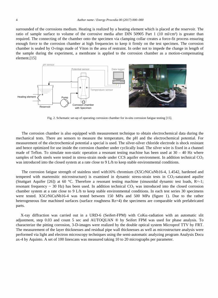
The objective was to simulate in-situ conditions (temperature 60 °C, corrosive environment) of a material exposed to dynamic mechanical stress and corrosive gas- saturated saline aquifer environment. The corrosion chamber is fixed directly onto the sample leaving the resonant testing machine unaffected (Fig. 2). During mechanical stress-strain tests a magnetically driven gear pump constantly pumps the corrosive media from the reservoir to the corrosion- and temperature-resistant corrosion chamber. The specimen is during the complete test
4 Author name / Energy Procedia 00 (2017) 000–000
surrounded of the corrosions medium. Heating is realized by a heating element which is placed at the reservoir. The ratio of sample surface to volume of the corrosive media after DIN 50905 Part 1 (10 ml/cm²) is greater than required. The connecting of the chamber onto the specimen via clamping collar creates a force-fit process ensuring enough force to the corrosion chamber at high frequencies to keep it firmly on the test specimen. The corrosion chamber is sealed by O-rings made of Viton in the area of restraint. In order not to impede the change in length of the sample during the experiment, a membrane is applied to the corrosion chamber as a motion-compensating element.[15]
Reservoir
Pump
Corrosion chamber with Specimen
Data loggerPotential sensor
Temperature sensor
pH sensor
Heating element
Fig. 2. Schematic set-up of operating corrosion chamber for in-situ corrosion fatigue testing [15].
The corrosion chamber is also equipped with measurement technique to obtain electrochemical data during the mechanical tests. There are sensors to measure the temperature, the pH and the electrochemical potential. For measurement of the electrochemical potential a special is used. The silver-silver chloride electrode is shock resistant and hence optimized for use inside the corrosion chamber under cyclically load. The silver wire is fixed in a channel made of Teflon. To simulate non-static operation a resonant testing machine has been used at 30 – 40 Hz where samples of both steels were tested in stress-strain mode under CCS aquifer environment. In addition technical CO2 was introduced into the closed system at a rate close to 9 L/h to keep stable environmental conditions.
The corrosion fatigue strength of stainless steel with16% chromium (X5CrNiCuNb16-4, 1.4542, hardened and
tempered with martensitic microstructure) is examined in dynamic stress-strain tests in CO2-saturated aquifer (Stuttgart Aquifer [26]) at 60 °C. Therefore a resonant testing machine (sinusoidal dynamic test loads, R=-1; resonant frequency ~ 30 Hz) has been used. In addition technical CO2 was introduced into the closed corrosion chamber system at a rate close to 9 L/h to keep stable environmental conditions. In each test series 30 specimens were tested. X5CrNiCuNb16-4 was tested between 150 MPa and 500 MPa (figure 1). Due to the rather heterogeneous fine machined surfaces (surface roughness Rz=4) the specimens are comparable with prefabricated parts.
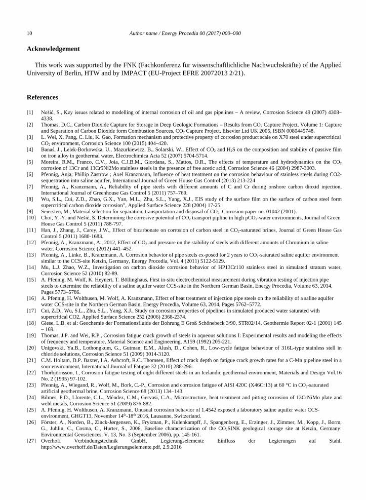
X-ray diffraction was carried out in a URD-6 (Seifert-FPM) with CoKα-radiation with an automatic slit adjustment, step 0.03 and count 5 sec and AUTOQUAN ® by Seifert FPM was used for phase analysis. To characterize the pitting corrosion, 3-D-images were realized by the double optical system Microprof TTV by FRT. The measurement of the layer thicknesses and residual pipe wall thicknesses as well as microstructure analysis were performed via light and electron microscopy techniques using the semi-automatic analyzing program Analysis Docu ax-4 by Aquinto. A set of 100 linescans was measured taking 10 to 20 micrographs per parameter.

Author name / Energy Procedia 00 (2017) 000–000 5
3. Results and Discussion
To explain the unusual high scatter range TN = 1:34 (figure 3) and differing results in corrosion fatigue tests extended analysis was performed selecting four specimens two that failed after maximum/minimum of cycles at low stress amplitude (250 MPa) and two that failed after maximum/minimum of cycles at high stress amplitude (450 MPa). Figure 3 demonstrates that at certain stress amplitudes the number of cycles differ by a factor of 50.
Fig. 3. Scatter range of number of cycles at certain stress amplitudes after fatigue testing.
Although each of the specimens was wrapped carefully after production an unknown number revealed surfaces scratches that may influence the endurance limit. Also all tests were conducted following a protocol and were cleaned with acetone and paper towels prior to assembly in the corrosion chamber. But it is not 100 % reliable if this was done in a proper way. Measurements of the electrochemical potential during fatigue tests show that cracking of the specimen is accompanied with a drop of the potential. Thus follows that both, mechanical load and the crack propagation are crucial for the potential change. For specimens with large number of cycles to failure the slope in the line of potential drop is rather large, whereas for specimens with small number of cycles the slope in the line of potential drop is small. But, even if the drop in electrochemical potential of approximately 100 mV reliably indicates the crack initiation prior to failure, still it is dependent on many issues, such as: pH, temperature, pressure, velocity of currency of the aquifer water, isolation of the corrosion chamber or sample surface conditions. Therefore these finding do not properly explain the large scatter range and unusual fatigue behavior. Because the hardness of the alloy is a measure of its endurance limit hardness tests were conducted with all 4 specimens revealing no difference and stable hardness about 335 HV10.
3.1. Possible influence of synthesized aquifer water
Ordering the numbers of failure within the S-N-plot results in three data sets as demonstrated by different types of lines in Fig. 4. These may be related to the charge of synthesized aquifer water.
Minimum of cycles Maximum of cycles
Stress amplitude σa in MPa
N
umbe
r of c
ycle
s Nb

6 Author name / Energy Procedia 00 (2017) 000–000
Fig. 4. Microstructure of X5CrNiCuNb16-4.
The large scatter range, the possibility of three charges and the very small coefficient of correlation r2 = 0.33 indicate a non-linear relationship of the considered variables giving only a 24% chance of linear relationship. The overall scatter range is TN=1:34 while Fig. 5 shows estimated scatter ranges for the different aquifer charges as follows: 1. Aquifer: TN=1:9,4, 2. Aquifer: TN=1:43,2, 3. Aquifer: TN=1:2,6 4. Aquifer: TN=1:48,4. Even here the differences between the charges are unusually high. Still, each of the 4 charges has been synthesized in a strictly orderly way following the same protocol to guarantee high quality and therefore reliability of the fatigue tests. Chemical analysis indicates no significant difference in composition or pH. It is highly doubtful, that even if Fig. 5 may assume otherwise the charge of Aquifer water is reason for this fatigue behavior.
3.2. Possible influence of distinct crack initiation and fracture
Multiple cracks were found throughout the entire sample area of X5CrNiCuNb16-4 and not –as expected- only within the sample area that is mechanically loaded highest [23]. In general pit formation on stainless steels is enhanced by chemical reactions, local changes of lattice energy within the steel`s surface and mechanical load. Within the microstructure an increase in dislocation number, grain boundaries, boundaries of precipitation phases e.g. carbides lead to local lattice mismatch resulting in higher local boundary energy [23] enhancing local corrosion. Pits may then consequently lead to crack formation and also accelerates crack propagation – both responsible for early failure.
All specimens were thoroughly visually analyzed at their crack surfaces to determine differences on the crack surface that may be related to high or low number of cycles to failure at certain stress amplitudes (Fig.5). Fig. 6 clearly points out that the surfaces of the cracks show darker areas related to impurities. But, these impurities were found on various surfaces with no significant correlation to the endurance limit. Note, the specimen in Fig. 5 was tested a high number of cycles prior to failure.

Author name / Energy Procedia 00 (2017) 000–000 7
Fig. 5. Crack surfaces after fatigue failure. Samples reveal impurities with no influence on endurance limit.
Additionally, all specimens revealed corrosion layers on the fatigue surface. These corrosion layers are mainly composed of iron carbonate (siderite, FeCO3) and iron hydroxide (Fe(OH)2) (Fig. 6, left). Once the crack opens the crack-flank surfaces corrode continuously during cyclic load leading to crack propagation perpendicular to the direction of load. Localized corrosion (pits: 0.1 mm deep and 0.2 mm diameter) is accompanied with cracks, but not necessarily identified as the cause of crack initiation and failure under mechanical load [15]. Both, the presence and the thickness of the corrosion layer could not be related to early failure. Concurrently all samples exposed striations indicating the opening and closing of the initial crack during cyclic load (Fig. 6, right). The number of striations was also not a matter of early or late failure
Fig. 6. Crack surfaces after fatigue failure. Samples reveal impurities with no influence on endurance limit.
Corrosion layer
Striations

8 Author name / Energy Procedia 00 (2017) 000–000
3.3. Possible influence of chemical composition
The analysis of the surface corrosion layers revealed multiple elements from the alloy, but in 50% of the corrosion layers aluminium was detected (Fig. 7).
Fig. 7. Surface image (left) of corrosion layer on crack flank and main elements indicating Al as impurity (right).
Because aluminium is not constituent of the alloy the chemical composition was double checked displaying aluminium also in the base material of all specimens. The presence of aluminium in the corrosion layer was correlated to samples with short number of cycles to failure and therefore is the only evidence for reason of lower endurance limits so far. In steels aluminium is added to obtain a fine grain microstructure. It also minimizes the decrease of mechanical properties related to aging processes and precipitates to aluminium nitrides in the presence of nitrogen promoting hardness (precipitation hardening) [27]. But, there is no information on the influence of aluminium on the corrosion fatigue behavior of steels. It is most likely that all of the aluminium analyzed is located in the base material and not in the corrosions layer. This excludes impurities from the aquifer water, the corrosion chamber or the test system.
3.4. Possible influence of inhomogeneous microstructure
After hardening and annealing the microstructure of X5CrNiCuNb16-4 reveals the typical needle-structure of martensite with embedded δ-ferrite (Fig. 8). White areas and darker spots that may be related to non metallic precipitations do not influence the mechanical properties because of their rather small diameter (5-10 µm). Samples with low number of cycles to failure revealed non-metallic inclusions that were distributed discontinuously lamellar within the alloy. But, these findings were also found in samples with high number of cycles to failure. It may be assumed that, impurities present in the base material consolidate during cyclic loading within the corrosive environment and then lead to unpredictable early failure. Perhaps some specimens contained more inclusions at the rupture cross section than other specimens explaining early failure. Possibly the endurance limit is dependent on the number of impurities within the alloy, but, because this is a statistic process no significant correlation may be given for microstructural appearance and endurance limit. Crack formation is correlated with local corrosion phenomena (pitting) resulting in inter crystalline corrosion. It may also be possible that these impurities lead to local corrosion phenomena, but again failure is not necessary a consequence of local corrosion.

Author name / Energy Procedia 00 (2017) 000–000 9
Fig. 8. Microstructure of X5CrNiCuNb16-4.
4. Conclusion
Corrosion fatigue tests were performed with possible injection pipe steel X5CrNiCuNb16-4, 1.4542 with 0.05% Carbon and 16% Chromium. Samples were tested in a resonant testing machine under stress-strain mode in CCS aquifer environment at 30 – 40 Hz to simulate non-static operation. Additionally technical CO2 was introduced into the closed system at a rate close to 9 L/h to keep stable environmental conditions. The unusual surface corrosion pattern [25] revealing FeCO3 and FeOOH as corrosion products as well as the unusual S-N plot, no typical corrosion fatigue limits, high scatter range 1:34 [15] and a maximal number of cycles to failure of 10 x 106 at a stress amplitude of 150 MPa demonstrate a distinct corrosion behaviour influencing mechanical performance under corrosive environment. Therefore four specimens were analysed thoroughly to display this unusual corrosion fatigue behaviour.
None of the following issues could precisely be correlated with early or late failure under corrosive environment: hardness of the specimen (335 HV10), crack initiation, crack propagation, aquifer water, state of microstructure of the steel. Statistical crack formation as well as characteristic crack propagation and fracture surfaces for one distinct stress amplitude are correlated with pit corrosion phenomena resulting in intercrystalline corrosion during crack propagation. Localized corrosion is present, but not definitely identified as the cause of crack initiation and failure.
Aluminium was found in all four specimens with the same mass percentage, but was not identified to be responsible for early rupture during corrosion fatigue tests. The microstructure revealed significant non-metallic inclusions which differed in quantity and type within each specimen and from specimen to specimen. But, no correlation was found for inclusions and early rupture. It was assumed that the quantity of inclusions and their position in the specimen may be responsible for failure during corrosion fatigue tests explaining the large scatter range. To determine the actual quantity of inclusions and the level of purity, further analysis of purity
Due to its susceptibility towards local corrosion DIN 6601 states that X5CrNiCuNb16-4, 1.4542 is unsuitable for pressure vessel application surrounded by CO2-saturated aquifer water. Even with low surface corrosion rates [16,25] X5CrNiCuNb16-4, 1.4542 shows unpredictable pitting behaviour and its mechanical properties under cyclic mechanical load have been proven to be highly dependent on alloy quality such as chemical composition and number of impurities. Therefore it is suitable for injection pipes in CCS environments only if monitored closely.
δ-ferrite
200 µm 50 µm
10 Author name / Energy Procedia 00 (2017) 000–000
Acknowledgement
This work was supported by the FNK (Fachkonferenz für wissenschaftlichliche Nachwuchskräfte) of the Applied University of Berlin, HTW and by IMPACT (EU-Project EFRE 20072013 2/21).
References
[1] Nešić, S., Key issues related to modelling of internal corrosion of oil and gas pipelines – A review, Corrosion Science 49 (2007) 4308–4338.
[2] Thomas, D.C., Carbon Dioxide Capture for Storage in Deep Geologic Formations – Results from CO2 Capture Project, Volume 1: Capture and Separation of Carbon Dioxide form Combustion Sources, CO2 Capture Project, Elsevier Ltd UK 2005, ISBN 0080445748.
[3] L. Wei, X. Pang, C. Liu, K. Gao, Formation mechanism and protective property of corrosion product scale on X70 steel under supercritical CO2 environment, Corrosion Science 100 (2015) 404–420.
[4] Banaś, J., Lelek-Borkowska, U., Mazurkiewicz, B., Solarski, W., Effect of CO2 and H2S on the composition and stability of passive film on iron alloy in geothermal water, Electrochimica Acta 52 (2007) 5704-5714.
[5] Moreira, R.M., Franco, C.V., Joia, C.J.B.M., Giordana, S., Mattos, O.R., The effects of temperature and hydrodynamics on the CO2 corrosion of 13Cr and 13Cr5Ni2Mo stainless steels in the presence of free acetic acid, Corrosion Science 46 (2004) 2987-3003.
[6] Pfennig, Anja; Phillip Zastrow ; Axel Kranzmann, Influence of heat treatment on the corrosion behaviour of stainless steels during CO2-sequestration into saline aquifer, International Journal of Green House Gas Control (2013) 213-224
[7] Pfennig, A., Kranzmann, A., Reliability of pipe steels with different amounts of C and Cr during onshore carbon dioxid injection, International Journal of Greenhouse Gas Control 5 (2011) 757–769.
[8] Wu, S.L., Cui, Z.D., Zhao, G.X., Yan, M.L., Zhu, S.L., Yang, X.J., EIS study of the surface film on the surface of carbon steel form supercritical carbon dioxide corrosion”, Applied Surface Science 228 (2004) 17-25.
[9] Seiersten, M., Material selection for separation, transportation and disposal of CO2, Corrosion paper no. 01042 (2001). [10] Choi, Y.-Y. and Nešić, S. Determining the corrosive potential of CO2 transport pipline in high pCO2-water environments, Journal of Green
House Gas Control 5 (2011) 788-797. [11] Han, J., Zhang, J., Carey, J.W., Effect of bicarbonate on corrosion of carbon steel in CO2-saturated brines, Journal of Green House Gas
Control 5 (2011) 1680-1683. [12] Pfennig, A., Kranzmann, A., 2012, Effect of CO2 and pressure on the stability of steels with different amounts of Chromium in saline
water, Corrosion Science (2012) 441–452. [13] Pfennig, A., Linke, B., Kranzmann, A. Corrosion behavior of pipe steels ex-posed for 2 years to CO2-saturated saline aquifer environment
similar to the CCS-site Ketzin, Germany, Energy Procedia, Vol. 4 (2011) 5122-5129. [14] Mu, L.J. Zhao, W.Z., Investigation on carbon dioxide corrosion behavior of HP13Cr110 stainless steel in simulated stratum water,
Corrosion Science 52 (2010) 82-89. [15] A. Pfennig, M. Wolf, K. Heynert, T. Böllinghaus, First in-situ electrochemical measurement during vibration testing of injection pipe
steels to determine the reliability of a saline aquifer water CCS-site in the Northern German Basin, Energy Procedia, Volume 63, 2014, Pages 5773–5786.
[16] A. Pfennig, H. Wolthusen, M. Wolf, A. Kranzmann, Effect of heat treatment of injection pipe steels on the reliability of a saline aquifer water CCS-site in the Northern German Basin, Energy Procedia, Volume 63, 2014, Pages 5762–5772.
[17] Cui, Z.D., Wu, S.L., Zhu, S.L., Yang, X.J., Study on corrosion properties of pipelines in simulated produced water saturated with supercritical CO2, Applied Surface Science 252 (2006) 2368-2374.
[18] Giese, L.B. et al: Geochemie der Formationsfluide der Bohrung E Groß Schönebeck 3/90, STR02/14, Geothermie Report 02-1 (2001) 145 – 169.
[19] Thomas, J.P. and Wei, R.P., Corrosion fatigue crack growth of steels in aqueous solutions I: Experimental results and modeling the effects of frequency and temperature, Material Science and Engineering, A159 (1992) 205-221.
[20] Unigovski, Ya.B., Lothongkum, G., Gutman, E.M., Alush, D., Cohen, R., Low-cycle fatigue behaviour of 316L-type stainless stell in chloride solutions, Corrosion Science 51 (2009) 3014-3120.
[21] C.M. Holtam, D.P. Baxter, I.A. Ashcroft, R.C. Thomsen, Effect of crack depth on fatigue crack growth rates for a C-Mn pipeline steel in a sour environment, International Journal of Fatigue 32 (2010) 288-296.
[22] Thorbjörnsson, I., Corrosion fatigue testing of eight different steels in an Icelandic geothermal environment, Materials and Design Vol.16 No. 2 (1995) 97-102.
[23] Pfennig, A., Wiegand, R., Wolf, M., Bork, C.-P., Corrosion and corrosion fatigue of AISI 420C (X46Cr13) at 60 °C in CO2-saturated artificial geothermal brine, Corrosion Science 68 (2013) 134–143.
[24] Bilmes, P.D., Llorente, C.L., Méndez, C.M., Gervasi, C.A., Microstructure, heat treatment and pitting corrosion of 13CrNiMo plate and weld metals, Corrosion Science 51 (2009) 876-882.
[25] A. Pfennig, H. Wolthusen, A. Kranzmann, Unusual corrosion behavior of 1.4542 exposed a laboratory saline aquifer water CCS-environment, GHGT13, November 14th-18th 2016, Lausanne, Switzerland.
[26] Förster, A., Norden, B., Zinck-Jørgensen, K., Frykman, P., Kulenkampff, J., Spangenberg, E., Erzinger, J., Zimmer, M., Kopp, J., Borm, G., Juhlin, C., Cosma, C., Hurter, S., 2006, Baseline characterization of the CO2SINK geological storage site at Ketzin, Germany: Environmental Geosciences, V. 13, No. 3 (September 2006), pp. 145-161.
[27] Overhoff Verbindungstechnik GmbH, Legierungselemente Einfluss der Legierungen auf Stahl, http://www.overhoff.de/Daten/Legierungselemente.pdf, 2.9.2016