Elevation of cytoskeletal protein breakdown in aged Wistar rat brain
Upload
independentCategory
view
5download
0
Controlling Mammalian Cell Spreading and CytoskeletalArrangement with Conveniently Fabricated Continuous
Wavy Features on Poly(dimethylsiloxane)
Xingyu Jiang,† Shuichi Takayama,† Xiangping Qian,† Emanuele Ostuni,†Hongkai Wu,† Ned Bowden,† Philip LeDuc,‡ Donald E. Ingber,‡ and
George M. Whitesides*,†
Department of Chemistry and Chemical Biology, Harvard University, 12 Oxford Street,Cambridge, Massachusetts 02138, and Departments of Pathology and Surgery,
Children’s Hospital and Harvard Medical School, Enders 1007, 300 Longwood Avenue,Boston, Massachusetts 02115
Received November 13, 2001. In Final Form: February 6, 2002
This paper reports a simple and versatile technique for generating structures on the surfaces of poly-(dimethylsiloxane) (PDMS), approximately sinusoidal waves with periods between 0.1 and 10 µm, and theuse of these structures to study cell contact guidance.1 The features are generated by stretching PDMSslabs mechanically, oxidizing them in an oxygen plasma, and allowing them to relax. These surface featuresare similar to photolithographically fabricated grooves that have traditionally been used to investigatecell contact guidance, although their edges are rounded rather than angular. Bovine capillary endothelialcells align and elongate on these features. The morphology and cytoskeletal structure of the aligned cellsare similar to those of cells described in previous studies of contact guidance on surfaces with other typesof topography. These observations and comparisons indicate that sharp edges in the features defining thegrooves are not essential in eliciting contact guidance. This technique provides a method for fabricatingmicrofeatures for the studies of the interactions between cells and their environment that does not requirea cleanroom or access to photolithographic tools.
Introduction
This paper describes an experimentally straightforwardtechnique to fabricate arrays of ordered sinusoidal featureson the surface of poly(dimethylsiloxane) (PDMS). It alsosummarizes the use of these structures to control cellspreading and to investigate the mechanisms employedby the cell to adapt to the topography of the substrate onwhich it rests. This technique does not require the use ofphotolithography: it is based on the spontaneous bucklingof PDMS whose surface has been oxidized in an air plasmaunder specific circumstances.2 It is possible to fabricateapproximately sinusoidal waves with wavelengths be-tween 0.1 and 10 µm; the corresponding depths of thesewaves are between 0.01 and 1 µm. These dimensions arewell suited for the study of the response of cells totopographical features in vitro, because cells react stronglyto features in this range of sizes.1
The tendency of surface topography to influence cellspreading is called “contact cue guidance”.1,3-6 Systematicstudies of contact cue guidance have used featuresfabricated photolithographically, sometimes coupled witha microelectromechanical system.7,8 Photolithography andassociated methods of fabrication have several disadvan-
tages, including the high cost and substantial inconve-nience of using clean room facilities, the inability togenerate gradients in features easily, and the opacity ofsilicon (the most commonly used material of fabrication)to visible light. The methodology described in this paperovercomes these difficulties: we demonstrate the ap-plication of the microfeatures fabricated using this simpletechnique in cell biology by controlling the spreading ofbovine capillary endothelial (BCE) cells with surfacesbearing patterns of sinusoidal waves.
The cross sections of these topographical features areapproximately smooth sinusoidal waves; we refer to themas “waves” (Figure 1A). We refer to features whose crosssections are square or V-shaped (both of which have sharpedges) as “grooves” (Figure 1B,C). Grooves with a rangeof depths and periodicities (from tens of nanometers tohundreds of micrometers) have been the substrates mostwidely used in studies of contact cue guidance.7-14 The
† Harvard University.‡ Children’s Hospital and Harvard Medical School.(1) Curtis, A.; Wilkinson, C. Biomaterials 1997, 18, 1573-1583.(2) Bowden, N.; Huck, W.; Paul, K.; Whitesides, G. M. Appl. Phys.
Lett. 1999, 75, 2557-2559.(3) Dunn, G. A. BioEssays 1991, 13, 541-543.(4) Brunette, D. M.; Chehroudi, B. J. Biomech. Eng. Trans. ASME
1999, 121, 49-57.(5) Flemming, R. G.; Murphy, C. J.; Abrams, G. A.; Goodman, S. L.;
Nealey, P. F. Biomaterials 1999, 20, 573-588.(6) Weiss, P. Int. Rev. Cytol. 1958, 7, 391.(7) Clark, P.; Connolly, P.; Curtis, A.; Dow, J.; Wilkinson, C.
Development 1987, 99, 439-448.(8) Brunette, D. Exp. Cell Res. 1986, 164, 11-26.
(9) Brunette, D. Exp. Cell Res. 1986, 67, 203-217.(10) Clark, P.; Connolly, P.; Curtis, A.; Dow, J.; Wilkinson, C.
Development 1990, 108, 635-644.
Figure 1. Schematic illustration of the features that we haveused (A) and those used historically (B, C). In (A), the ratio ofwavelength to amplitude of the waves is approximately 10.
3273Langmuir 2002, 18, 3273-3280
10.1021/la011668+ CCC: $22.00 © 2002 American Chemical SocietyPublished on Web 03/20/2002

cylindrical surfaces of optical fibers have also been usedin these studies.15,16 Continuous sinusoidal wave featurescomparable in size with the grooves that are commonlyused have not been systematically investigated.8,17
The ability to control the topography of surfaces offersone approach to answering certain types of questions incell biology concerning the influence of topography oncellular behavior. Many hypotheses about the mechanismof cellular reaction to topographical features are centeredon the geometrical details of the features that the cellsmay encounter.18 For example, some investigators suggestthat cells sense edges and require an abrupt change intopography (as observed in grooves or ridges) in order toreact to the substrate.18 The grooves used previously allhadsharpedges,andcylindersarenot continuous features.It has, therefore, been difficult to study how cells react tocontinuous topographies that do not present sharp edges.Waves represent a unique topography that is bothcontinuous (like grooves) and have no sharp edges in shape(like cylinders). We have compared cellular reactions tosmooth contoured surfaces (e.g., waves) and contouredsurfaces that have sharp edges (e.g., grooves) and il-lustrated approaches to some questions concerning themechanism of contact guidance. Wave features may alsobe more relevant to physiological contact cue guidancethan angular features, since there are few sharp edges inthe cellular environment experienced by cells inside thebody.
Results and DiscussionSurface Features. We generated waves with sizes
between hundreds of nanometers and tens of micrometers.These dimensions are compatible with studies in cellbiology, because individual cells normally have dimensionsof tens of micrometers. These structures were fabricatedas outlined in Figure 2, route A. This method is simplerthan that developed previously (where the PDMS washeated, oxidized, and allowed to cool).2 The waves arewell ordered over distances of 5 mm and are ideal forstudies in cell biology because high perfection and long-range order are seldom required in these studies. Imagesfrom both light microscopy (Figure 2, insert I) and scanningelectron microscopy (Figure 2, insert II) confirm that thefeatures produced have regular periodicity and amplitude.The dimensions of the waves can be controlled easily byvarying the duration of oxidation.2 The longer the oxida-tion, the larger the wavelength and the amplitudes (Figure3). There is a practical limit, however, to the sizes of wavesthat can be generated. Because oxidized PDMS is brittle,crack defects that run perpendicular to waves become morecommon at longer oxidation times (>30 min). Thisrestriction dictates the upper limit of the amplitude andwavelength of these waves at 2 and 20 µm, respectively.Other ways to vary the wavelengths and amplitudes ofthe waves include controlling the thickness and elasticmodulus of the PDMS slab. Thin and soft PDMS slabstend to produce large waves.2
We also generated gradients of waves using the methoddescribed in Figure 2, route B. As in method A, we wrappeda PDMS slab around a cylinder. In addition, we placedanother PDMS slab in tangential contact with the bentPDMS slab. The flat top slab shields the bent slab fromoxidation increasingly as the bent and flat surfaces becomecloser to each other (from 0% shielding in areas far awayfrom the top slab to 100% shielding on the area of contactbetween the two PDMS slabs). This procedure gives agradient of waves whose wavelengths decrease from amaximum of 10 to 0 µm (Figure 2, insert III). The abilityto generate a gradient in the dimensions of features withease is another advantage that this new method has overpreviously reported techniques.2
The mechanism by which the waves on the surface aregenerated can be summarized qualitatively as follows(more quantitative analysis can be found elsewhere2,19,20):bending the PDMS slab induces mechanical stress on itssurface. When oxidized, the PDMS surface is chemicallymodified: the exposed Si-CH3 groups are oxidized to Si-OH groups and form a thin, stiff oxide layer. When releasedfrom the cylinder, the bulk PDMS returns approximatelyto its original shape; this relaxation places the rigid surfaceoxide under compressive stress. This stress is relieved bybuckling into continuous and periodic waves.
This method of generating microfeatures offers severaladvantages, relative to photolithography, as a methodol-ogy: (i) It is more convenient experimentally thanphotolithography, since it does not require masks or accessto clean room facilities. (ii) It generates gradients easily.(iii) It generates features with rounded edges. (iv) It canbe applied to PDMS; PDMS is a transparent elastomerhaving the optical properties needed for microscopy andthe mechanical properties needed in studies where cellsneed to be stretched. The disadvantage of this method isthe limited range of sizes and geometries that it producesand the fact that the depth and wavelength cannot beeasily controlled independently.
Response of BCE Cells to Surface Waves. BCE cellsshow clear evidence of contact guidance on a contouredsurface of PDMS. Within 2 h of cell attachment to thesurface, cells respond to the topography; by 24 h, thecells have adapted fully to these features and displaydistinct elongated cell morphology. Figure 4A shows amonolayer of cells on wave topography. The cells elongateand spread parallel to the direction of the waves. Incontrast, cells on a flat substrate show random orientationand less elongation (Figure 4B). Statistical analysis showsthat cells are increasingly guided by the waves as thewavelength and amplitude increase, as indicated byincreases in the elongation index and decreases in theaverage orientation angle (Figure 5B) (see ExperimentalSection for detailed explanation of the method for quan-tification). Both elongation and orientation angle level offwhen the wavelength is above 8 µm. It appears that thewaves control the spreading of the cells maximally whenthe wavelength is above 8 µm for the size range tested.
To investigate some of the ultrastructures of cells spreadon surfaces patterned with waves, we used confocalscanning microscopy to examine the complex cytoskeletonon contoured surfaces. Actin stress fibers and microtubulesalign with the general direction of the contoured surface(Figure 6). Within one cell, there are several levels oforganization of the cytoskeleton. For instance, on differentplanes parallel to the mean plane of the surface, actin
(11) Rovensky, Y.; IL, S.; Vasiliev, J. Exp. Cell Res. 1971, 65, 193-201.
(12) denBraber, E. T.; deRuijter, J. E.; Ginsel, L. A.; vonRecum, A.F.; Jansen, J. A. Biomaterials 1996, 17, 2037-2044.
(13) Mrksich, M.; Chen, C. S.; Xia, Y.; Dike, L. E.; Ingber, D. E.;Whitesides, G. M. Proc. Natl. Acad. Sci. U.S.A. 1996, 93, 10775-10778.
(14) Takayama, S.; Ostuni, E.; Qian, X.; McDonald, J. C.; Jiang, X.;LeDuc, P.; Wu, M. H.; Ingber, D. E.; Whitesides, G. M. Adv. Mater.2001, 13, 570-574.
(15) Curtis, A. S. G.; Varde, M. J. Natl. Cancer Inst. 1964, 33, 15-26.(16) Rovensky, Y.; Samoilov, V. J. Cell Sci. 1994, 107, 1255-1263.(17) Rosdy, M.; Grisoni, B.; Clauss, L. Biomaterials 1991, 12, 511-
517.(18) Curtis, A. S. G.; Clark, P. Crit. Rev. Biocompat. 1990, 5, 343-
362.
(19) Bowden, N.; Brittain, S.; Evans, A. G.; Hutchinson, J. W.;Whitesides, G. M. Nature 1998, 393, 146-149.
(20) Huck, W. T. S.; Bowden, N.; Onck, P.; Pardoen, T.; Hutchinson,J. W.; Whitesides, G. M. Langmuir 2000, 16, 3497-3501.
3274 Langmuir, Vol. 18, No. 8, 2002 Jiang et al.

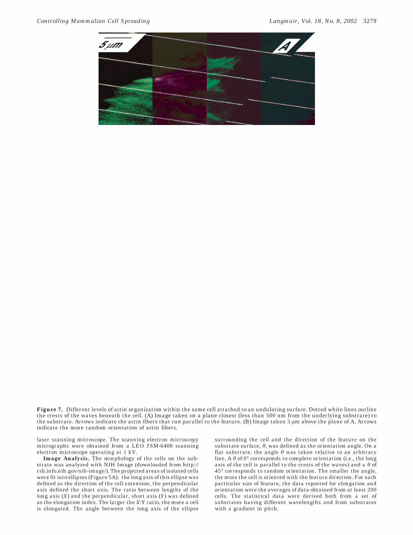
fibers organize into quite different macroassemblies. Actinfibers near the substrate (<500 nm) are most stronglyguided by the waves; most fibers are straight and extendalong the features on the surface (Figure 7A), while actinfibers imaged in a parallel plane 3 µm away from thesurface (toward the dorsal side of the cell) appear to bemore random in orientation (Figure 7B). These findingsconfirm previous reports on the alignment of actin fibersthat many cell types exhibit when cultured on groovedsubstrates.21-23
We then visualized vinculin to identify focal adhesioncomplexes (FACs). Although some FACs appear to becolocalized with actin fibers (especially at the termini of
these fibers), there is no general tendency for the FACsto be localized in either the troughs or the crests on thesurface features (Figure 8). We infer that, at this stage(36 h after seeding), cells adhere to the substratesconformally, without any preference for adhesion to thetroughs or the crests of the wave.
Comparison of Cell Alignment to Waves andGrooves of Similar Sizes. BCE cells clearly respond tosurface waves, and this response is manifested both intheir morphology and in their cytoskeleton organization.We have compared their responses to waves and groovesand quantified the differences in their reactions to thetwo different types of substrates. The groove features thatwe made are illustrated schematically in Figure 1B. Thegrooves had the same wavelength and amplitudes as thesinusoidal waves fabricated by oxidizing stretched PDMS.Table 1 compares the average orientation angles of BCEcells on two sets of waves and grooves. The results areindistinguishable: the cells do not sense a difference
(21) Oakley, C.; Brunette, D. M. Cell Motil. Cytoskeleton 1995, 31,45-58.
(22) Wojciakstothard, B.; Curtis, A. S. G.; Monaghan, W.; McGrath,M.; Sommer, I.; Wilkinson, C. D. W. Cell Motil. Cytoskeleton 1995, 31,147-158.
(23) den Braber, E. T.; de Ruijter, J. E.; Ginsel, L. A.; von Recum,A. F.; Jansen, J. A. J. Biomed. Mater. Res. 1998, 40, 291-300.
Figure 2. Illustration of the process for generating waves on the surface of PDMS. Top: Route A illustrates the generation ofa surface that has waves with uniform pitch. A PDMS slab was first wrapped around a glass cylinder, oxidized in a plasma, andthen unwrapped. Waves form in the direction of maximal stress relief. Route B sketches the generation of a surface with a continuousgradient of waves. Inserts I and III are bright field optical micrographs. Insert II is a scanning electron micrograph. Bottom: Oncethe features are made, the surface is silanized and cast into a UV curable polymer to make the master to fabricate more PDMSsubstrates. See Experimental Section for details.
Controlling Mammalian Cell Spreading Langmuir, Vol. 18, No. 8, 2002 3275

between the waves and grooves. Actin filaments andmicrotubule organization of cells on both features aresimilar to each other. We conclude that cells react to wavesin essentially the same way as they do to grooves. To ourknowledge, this report is the first one to compare cellularresponses to wave and groove features of comparable sizes.
The Mechanism of Contact Guidance. The mech-anism of contact guidance of eukaryotic cells is still notwell understood.1 Several hypotheses have been pro-posed: Ohara and Buck suggested that cellular alignmentto grooved surfaces is caused by the alignment of focaladhesion complexes.24 This suggestion was later provennot to be universally applicable for all cases of contactguidance.25 Dunn explained cellular alignment using amodel based on the tendency of stress fibers to form instraight lines. Since linear actin fibers cannot form acrossthe ridges and conform to the surface at the same time(as doing so would make the fibers bend up and down onthe surface contours), fibers perpendicular to these ridgeswill not form. Only those fibers parallel with the grooveswill tend to form, and thus the stress fibers will force cellsto elongate and spread along the direction of the features.26
This theory was later contended by Curtis and Clark, whosuggested that cell alignment togroovedsurfaces isaresultof discontinuities in the shape the surfaces. They observethat actin nucleation sites tend to form at these sharpedges. This observation led them to hypothesize thatcytoskeletal polymerization (particularly actin polymer-ization) tends to occur on or near the sharp edges in thesubstrate and therefore biases cell spreading to occur alongthe sharp edges.18 While hypotheses about the mechanism
of contact guidance abound, none can account for allobservations concerning topographical contact guidance.It is clear that the major cellular components responsiblefor these observations include cytoskeletal elements suchas microfilaments and microtubules,22 outside-to-insidesignal transducers such as integrins,27 and stress receptorssuch as chloride channels.28 Microfeatures also affect geneexpression and protein synthesis and may influence otherparts of the cellular machinery.29 It is not yet clear howthe components involved in contact guidance interact andproduce the observed cellular response to microfeaturedsurface.
Our studies provide some additional insights into thefactors that determine the behaviors of cells on micro-structures. The most significant finding of this study is
(24) Ohara, P.; Buck, R. Exp. Cell Res. 1979, 121, 235-249.(25) Dunn, G. A.; Brown, A. F. J. Cell Sci. 1986, 83, 313-340.(26) Dunn, G. A.; Heath, J. P. Exp. Cell Res. 1976, 101, 1-14.
(27) Oakley, C.; Brunette, D. M. J. Cell Sci. 1993, 106, 343-354.(28) Curtis, A.; Wilkinson, C. In Biochemical Society Symposia;
Portland Press: London, 1999; pp 15-26.(29) Chou, L. S.; Firth, J. D.; Uitto, V. J.; Brunette, D. M. J. Biomed.
Mater. Res. 1998, 39, 437-445.
Figure 3. The dependence of wavelengths and amplitude onoxidation time. Increased oxidation time resulted in increasedamplitude and wavelength: amplitude, open squares; wave-length, solid diamonds.
Table 1. A Comparison of Cell Orientation on Groovesand Wavesa
featurecharacterization wavelength/µm
orientation angle(deg) ((std)
waves 5 20 ( 3grooves 5 18 ( 3waves 10 14 ( 4grooves 10 13 ( 3
a Orientation angles on wave features are similar to those ongrooves.
Figure 4. Comparison of cell monolayers on flat and wavysubstrates. Cell morphology is visualized using Alexa Fluor488-conjugated phalloidin that binds to actin filaments withnuclei (blue) stained with 4′,6-diamidino-2-phenylindole (DAPI).(A) A confluent layer of BCE cells on a PDMS substrate withfeatures. The grids on both sides of the picture indicate crestsand direction of the waves. (B) Confluent layer of cells on a flatPDMS substrate as a control.
3276 Langmuir, Vol. 18, No. 8, 2002 Jiang et al.

the fact that the waves and grooves elicit similar cellularresponses. The major topographical factor that distin-guishes surface waves and surface grooves is the presenceof sharp edges in the latter. Since both waves and groovescontrol cell spreading in the same way, we conclude thatsharp edges are not required to elicit cell contact guidance.This report, we believe, is the first one that uses systematicvariation in the fine details of the geometries of themicrofeatures to prove that the presence of sharp edgesin the microstructure is not a crucial factor in determiningcell response to surface topography. Since the mechanismsinvolved in cellular response to topography are still quitecomplex, we are, therefore, unable to construct a mecha-nistic model that accounts for all the observationsconcerning topographical responses of cells.
ConclusionWe have described a convenient method to fabricate
surfaces patterned with ordered arrays of waves to studythe interaction between cells and topographical elements.This report is the first to use only wavelike features(continuous and without sharp edges) to control cellspreading on a surface. BCE cells respond to wave andgroove topographies in similar ways. We conclude thatthe sharp edges that characterize grooves are not requiredto guide cell spreading.
We also believe that the convenience of this techniquewill find applications in fundamental studies of theinteraction between cells and artificial materials and indirecting growth of endothelial capillaries in tissueengineering.
Experimental Section
Generation of Desired Microstructures on the Sur-face. The wave features were fabricated by wrapping a PDMSslab (typically 5 cm × 3 cm × 0.5 cm) around a glass cylinder(diameter ) 4 cm) and then exposing it to an oxygen plasma for1-30 min at a pressure between 1 and 2 Torr. After plasmaoxidation, the slab was carefully released from the cylinder(Figure 2). To fabricate a master from which additional substratescan be made, we silanized the substrate with (tridecafluro-1,1,2,2,-tetrahydrooctyl)-1-trichlorosilane (United Chemical Tech-nologies, Bristol, PA) and then cast a UV-activated Epo-Tekpolymer (Epoxy Technology, Boston, MA) on the silanized PDMSsurface. The hardened polymer was used as the master to produceadditional PDMS substrates (Figure 2, bottom). These unoxidizedPDMS substrates were used for the studies in cell biology.
The grooved substrates that we used for comparison with thesubstrates having waves were fabricated by conventional pho-tolithography.30 Briefly, a layer of photoresist (Shipley 1805,Microlithography Chemical Corporation, Newton, MA) wasapplied to a silicon wafer by spin coating. The thickness of the
Figure 5. (A) Illustration of the measurement of elongation index, X/Y, and orientation angle, θ. (B) Plots of elongation X/Y (solidsquares) and orientation angle θ (open circles) versus the size of the wave features. See text for the methods of measurement. Thelarger the value of elongation, the more elongated the cell is. The smaller the orientation angle, the more aligned the cell is. Errorbars represent one standard deviation from the mean.
Controlling Mammalian Cell Spreading Langmuir, Vol. 18, No. 8, 2002 3277

photoresist was controlled by the spin speed. We then exposedthe photoresist through photomasks using standard contact-modephotolithography with broadband UV light;31 the exposed resistwas etched in a KOH-based developer (Microposit 351 developer,Shipley Co., Inc. Marlborough, MA). We then silanized theresulting structure on the silicon wafer with the aforementionedsilane in a vacuum desiccator overnight and used it as a masterto produce substrates with rectangular grooves by molding PDMSagainst it.32
Cell Culture and Attachment to Substrates. Primarybovine capillary endothelial cells (passages 9-12)33 were grownin Dulbecco’s Modification of Eagle’s Medium (JRH Biosciences,Kansas City, MO) containing 10% bovine calf serum (HycloneLaboratories, Pittsburgh, PA) and glutamine/penicillin/strepto-mycin (Irvine Scientific, Santa Ana, CA). In addition, basicfibroblast growth factor (bFGF, Sigma) was present at 5 ng/mLin all media. All cell cultures were maintained at 37 °C in ahumidified 10% CO2 incubator. PDMS substrates were firstcoated with fibronectin (Sigma, St. Louis, MO, 5 µg/mL in
phosphate buffered saline (PBS)) for an hour in order to allowa uniform layer of fibronectin to adsorb on the PDMS substratesto facilitate cell attachment. Cells were seeded onto fibronectin-coated substrates with a density of 105 cells/mL and allowed toattach and spread for 36 h. The cells then were fixed with 4%paraformaldehyde in PBS for 15 min and subsequently perme-abilized with 0.3% Triton-X solution in PBS (5 min).
Immunofluorescence and Microscopy. Actin stress fiberswere visualized using phalloidin-Alexa Fluor 488 (MolecularProbes, Eugene, OR). Microtubules and vinculin were visualizedby standard immunofluorescence procedures: permeabilized cellswere incubated with wash buffer (PBS containing 5% bovineserum albumin) for 1 h at room temperature to inhibit nonspecificadsorption. Primary antibodies raised against vinculin andR-tubulin from mice (Sigma) were applied for 12 h at 4 °C indilutions of 1:200 in the wash buffer, and the cells were washedextensively with wash buffer. Anti-mouse IgG (from sheep)conjugated with Texas red (Amersham, Newark, NJ) was appliedtogether with phalloidin conjugates, for 1 h at room temperaturein dilutions of 1:40 in the wash buffer. Samples were mountedusing Vectashield mounting media from Vector Laboratories(Burlingame, CA). Cell nuclei were visualized through 4′,6-diamidino-2-phenylindole (DAPI) contained in the mountingmedia. Fluorescence images were captured with a Hamamatsucharge coupled device camera mounted on a Leica invertedmicroscope. Confocal images were obtained using a Leica confocal
(30) Rogers, J. A.; Paul, K. E.; Jackman, R. J.; Whitesides, G. M.Appl. Phys. Lett. 1997, 70, 2658-2660.
(31) Moreau, W. M. Semiconductor Lithography: Principles andMaterials; Plenum: New York, 1988.
(32) Xia, Y.; Whitesides, G. M. Angew. Chem., Int. Ed. Engl. 1998,37, 550-575.
(33) Ingber, D. E. Proc. Natl. Acad. Sci. U.S.A. 1990, 87, 3579-3583.
Figure 6. Confocal images of cells on the waves showing actin and microtubule organization. (A) A representative cell whose actinwas stained with phalloidin-Alexa Fluor 488 (green). (B) The same cells whose microtubules were stained with Texas red throughantibodies. The straight white lines indicate the crests and orientation of the waves beneath the cell. (C) The substrate beneaththe cell. This image is collected in the “reflection” mode where all the light is reflected from the sample. Simple difference betweenbrightness does not correctly reflect the heights of the sample. Noise in this image is due to artifacts.
3278 Langmuir, Vol. 18, No. 8, 2002 Jiang et al.
laser scanning microscope. The scanning electron microscopymicrographs were obtained from a LEO JSM-6400 scanningelectron microscope operating at 1 kV.
Image Analysis. The morphology of the cells on the sub-strate was analyzed with NIH Image (downloaded from http://rsb.info.nih.gov/nih-image/). The projected areas of isolated cellswere fit into ellipses (Figure 5A): the long axis of this ellipse wasdefined as the direction of the cell extension, the perpendicularaxis defined the short axis. The ratio between lengths of thelong axis (X) and the perpendicular, short axis (Y) was definedas the elongation index. The larger the X/Y ratio, the more a cellis elongated. The angle between the long axis of the ellipse
surrounding the cell and the direction of the feature on thesubstrate surface, θ, was defined as the orientation angle. On aflat substrate, the angle θ was taken relative to an arbitraryline. A θ of 0° corresponds to complete orientation (i.e., the longaxis of the cell is parallel to the crests of the waves) and a θ of45° corresponds to random orientation. The smaller the angle,the more the cell is oriented with the feature direction. For eachparticular size of feature, the data reported for elongation andorientation were the averages of data obtained from at least 200cells. The statistical data were derived both from a set ofsubstrates having different wavelengths and from substrateswith a gradient in pitch.
Figure 7. Different levels of actin organization within the same cell attached to an undulating surface. Dotted white lines outlinethe crests of the waves beneath the cell. (A) Image taken on a plane closest (less than 500 nm from the underlying substrate) tothe substrate. Arrows indicate the actin fibers that run parallel to the feature. (B) Image taken 3 µm above the plane of A. Arrowsindicate the more random orientation of actin fibers.
Controlling Mammalian Cell Spreading Langmuir, Vol. 18, No. 8, 2002 3279

Acknowledgment. This work is supported by theDefense Advanced Research Planning Agency (DARPA)/Space and Naval Warfare Systems Command, DARPA/Office ofNaval Research, the National Science Foundation(NSF ECS-9729405), and the National Institutes of Health(NIH GM30367). S.T. is a Leukemia Society of America
Fellow and thanks the society for a postdoctoral fellowship.X.Q. thanks NSERC of Canada for a postdoctoral fellow-ship. D.E.I. is grateful to NIH (CA45548) for financialsupport.
LA011668+
Figure 8. Confocal images of BCE cells on the waves showing actin organization and focal adhesion distribution. (A) One cell whoseactin is stained with Alex 488 (green). (B) The same cells whose vinculin is stained with Texas red to visualize focal adhesion. (C)Composite image of A and B. Dotted white lines follow the crests of the waves beneath the cell.
3280 Langmuir, Vol. 18, No. 8, 2002 Jiang et al.
Copyright © 2022 FDOKUMEN