Control Electronics Integration toward Endoscopic Capsule ...
29
HAL Id: hal-01515997 https://hal.inria.fr/hal-01515997 Submitted on 28 Apr 2017 HAL is a multi-disciplinary open access archive for the deposit and dissemination of sci- entific research documents, whether they are pub- lished or not. The documents may come from teaching and research institutions in France or abroad, or from public or private research centers. L’archive ouverte pluridisciplinaire HAL, est destinée au dépôt et à la diffusion de documents scientifiques de niveau recherche, publiés ou non, émanant des établissements d’enseignement et de recherche français ou étrangers, des laboratoires publics ou privés. Distributed under a Creative Commons Attribution| 4.0 International License Control Electronics Integration toward Endoscopic Capsule Robot Performing Legged Locomotion and Illumination Oscar Alonso, Angel Diéguez To cite this version: Oscar Alonso, Angel Diéguez. Control Electronics Integration toward Endoscopic Capsule Robot Performing Legged Locomotion and Illumination. 18th International Conference on Very Large Scale Integration (VLSISOC), Sep 2010, Madrid, Spain. pp.312-338, 10.1007/978-3-642-28566-0_13. hal- 01515997
-
Upload
khangminh22 -
Category
Documents
-
view
1 -
download
0
Transcript of Control Electronics Integration toward Endoscopic Capsule ...
HAL Id: hal-01515997https://hal.inria.fr/hal-01515997
Submitted on 28 Apr 2017
HAL is a multi-disciplinary open accessarchive for the deposit and dissemination of sci-entific research documents, whether they are pub-lished or not. The documents may come fromteaching and research institutions in France orabroad, or from public or private research centers.
L’archive ouverte pluridisciplinaire HAL, estdestinée au dépôt et à la diffusion de documentsscientifiques de niveau recherche, publiés ou non,émanant des établissements d’enseignement et derecherche français ou étrangers, des laboratoirespublics ou privés.
Distributed under a Creative Commons Attribution| 4.0 International License
Control Electronics Integration toward EndoscopicCapsule Robot Performing Legged Locomotion and
IlluminationOscar Alonso, Angel Diéguez
To cite this version:Oscar Alonso, Angel Diéguez. Control Electronics Integration toward Endoscopic Capsule RobotPerforming Legged Locomotion and Illumination. 18th International Conference on Very Large ScaleIntegration (VLSISOC), Sep 2010, Madrid, Spain. pp.312-338, �10.1007/978-3-642-28566-0_13�. �hal-01515997�
Control Electronics Integration toward Endoscopic
Capsule Robot Performing Legged Locomotion and
Illumination
Oscar Alonso1, Angel Diéguez
1
1 Electronics Department, Universitat de Barcelona, Martí i Franquès nº1, 08028 Barcelona,
SPAIN
Abstract. Miniaturization of sensors and actuators up to the point of active
features in endoscopic capsules, such as locomotion or surgery, is a challenge.
VECTOR endoscopic capsule has been designed to be the first endoscopic
capsule with active locomotion. It is equipped with mini-legs driven by
Brushless DC (BLDC) micro motors. In addition it can be also equipped with
some other sensors and actuators, like a liquid lens, that permits to enable
advanced functions. Those modules are managed by an Application Specific
Integrated Circuit (ASIC) specifically designed for the VECTOR capsule. The
ASIC is a complete System-On-Chip (SoC) and integrates all the electronics
needed to enable the legged locomotion and the sensing and actuating functions
of the capsule in an unique chip. The SoC also permits other functions for
endoscopic capsules such as drug delivery and biopsy. The size of the SoC is
5.1 mm x 5.2 mm in a 0.35 µm high voltage CMOS technology.
Keywords: Active capsular endoscopy, gastrointestinal exploration, Brushless
motor, liquid lens, control ASIC, electronics.
1 Introduction
The gastro intestinal (GI) tract, like any other part of the human body may be affected
by infections or diseases. Because of the length of the GI tract and its location inside
the human body, the detection and diagnosis of these diseases is very complicated.
The method used by doctors when analyzing the GI tract is endoscopy. Basically, the
endoscopy consists in introducing, inside the GI tract, a thin tube with a video camera
and light at the beginning. The basic function of this system is to show to doctors the
GI tract without any need of surgery. The tube can be inserted both orally and
rectally. Endoscopy in the digestive tract is named differently depending on the area
under study and the applied techniques, the procedures most widely used are:
Esofagogastruoduodenoscopy (EGD), which includes the study of the
oesophagus, stomach and duodenum. This procedure is used to discover the
reason for swallowing difficulties, nausea, vomiting, reflux, bleeding,
indigestion, abdominal pain, or chest pain. In particular, for this procedure the
endoscope can be introduced through the nose or the mouth of the patients,
who have been previously sedated in order to reduce the pain during the
examination. In addition, the scope also blows air into the stomach in order to
expand the folds of tissue and give the possibility of look through the folders.
Double Balloon Enteroscopy, which is used to study the small bowel. It is a
newly developed endoscopic method which permits to explore the small
bowel without any need of surgical intervention [1]. Using a simple push and
pull method two balloons are used in this procedure to examine the small
intestine in steps approximately 40 cm long.Double balloon endoscopy [2] is
indicated in cases of unclear bleeding in the digestive tract, Chron’s disease,
unclear chronic diarrhoea, abdominal pain, intestinal polyposis, intestinal
dysplasia and Celiac disease.
Push Enteroscope, which is also used for the study of the small bowel. During
this procedure, a long, narrow, flexible gastrointestinal endoscope, known as
a push enteroscope, is advanced into the upper gastrointestinal tract to
examine and evaluate the proximal section (first one third) of the small bowel
[3]. This procedure is indicated when the doctors are not able to identify the
cause of obscure bleeding or some other GI disorder.
Colonoscopy, which is used to study the colon. The colonoscopy is the less
invasive technique that uses a scope to examine the colon and the distal part
of the small bowel. Colonoscopy has been available since the early 1970s and
has become critical to the diagnosis and management of colorectal disorders
4].Although colonoscopy is a safe procedure, complications can sometimes
occur. These include perforation a puncture of the colon walls, which could
require surgical repair. Sedation during the examination, post-procedural
abdominal pain and irritable bowel syndrome are the main drawbacks.
However, with this procedure biopsies can be taken of any abnormal areas at
the same time as the screening or diagnostic test is being done. Any polyps
found can be removed during this procedure [4-8].
Flexible Sigmoidescopy (FS), which is similar to the colonoscopy. However,
this procedure only examines the region from the rectum to the colon (also
known as sigmoid). This procedure is one of the screening modalities for
colorectal cancer. From the point of view of screening, FS clearly cannot
completely exclude the presence of colon cancer in all asymptomatic people.
However, flexible sigmoidoscopy every 5 years with or without fecal occult
blood test (FOBT) is one of the screening methods recommended by major
professional organizations. It identifies 50 to 70% of the advanced neoplasms,
if any discovery of a distal neoplasia is followed up with a total examination
of the colon by colonoscopy [9-10].
Endoscopy allows us to examine the digestive tract. Nevertheless, it also has some
disadvantages. For example, it is a painful treatment for the patient because requires
the introduction of a tube inside the human body (the scope has a diameter of 7-8 mm,
however the pain associated with the procedure is not caused by the insertion of the
scope but from inflating of the colon in order to do the inspection). Furthermore,
endoscopy can not access the entire GI tract. For example, doctors are only able to
study a small part of the small fine. Finally, endoscopy is not always effective, as the
conditions are so adverse in the GI tract (long extension, folds of tissue, poor lighting)
that the doctor is not always able to detect diseases, requiring a second observation or
some alternative method.
The need to improve the existing method and the fact that the number of people
around the world that access to endoscopy is about 15 million [11] has led to the
emergence of alternative methods like capsular endoscopy.
Capsular endoscopy is a minimally invasive procedure that permits to study the
whole GI tract. Capsular endoscopy consists in a small capsule with the shape of a
pill, which contains some electronic elements needed to perform the same task as the
traditional endoscopy. In standard devices such electronic elements are basically a
tiny camera, some LEDs for the illumination of the GI tract, a radiofrequency (RF)
system needed to transmit the acquired images to the doctors and a battery (needed to
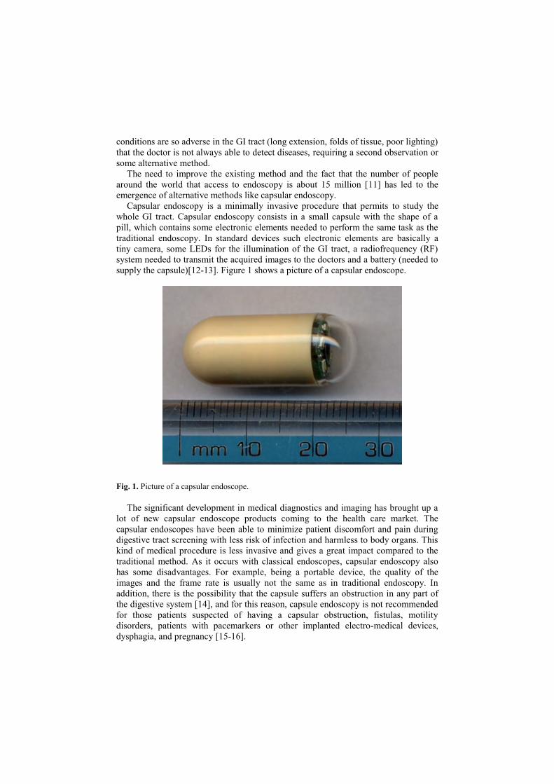
supply the capsule)[12-13]. Figure 1 shows a picture of a capsular endoscope.
Fig. 1. Picture of a capsular endoscope.
The significant development in medical diagnostics and imaging has brought up a
lot of new capsular endoscope products coming to the health care market. The
capsular endoscopes have been able to minimize patient discomfort and pain during
digestive tract screening with less risk of infection and harmless to body organs. This
kind of medical procedure is less invasive and gives a great impact compared to the
traditional method. As it occurs with classical endoscopes, capsular endoscopy also
has some disadvantages. For example, being a portable device, the quality of the
images and the frame rate is usually not the same as in traditional endoscopy. In
addition, there is the possibility that the capsule suffers an obstruction in any part of
the digestive system [14], and for this reason, capsule endoscopy is not recommended
for those patients suspected of having a capsular obstruction, fistulas, motility
disorders, patients with pacemarkers or other implanted electro-medical devices,
dysphagia, and pregnancy [15-16].
The capsular endoscopes are known by different names such as wireless capsule
camera, video pill, PillCam [12,17], EndoCapsule [13] or Sayaka [18]. Their shape
look similar to a pill or capsule and they are able to see areas, which traditional
endoscopes are unable to see. Capsular endoscopes also gives extra convenience to
the patient. After swallowing one of the aforementioned capsules, the patient may
leave the hospital and return later after 8 hours. During this long period, the capsule
captures images along the gastrointestinal (GI) tract while the patient is continuing the
daily activity.
Although pill-shaped micro-cameras have existed for over 9 years by now, these
systems are passive and are dependent to the peristaltic movement of the gastric wall
to actively locomote. The camera takes thousands of pictures as it passes through the
GI tract, but its position during this time cannot be controlled. Therefore, many
research institutions around the world are exploring the possibility to have an active
endoscopic device for medical inspection and therapy in the form of capsular robot
[19].
Compared to traditional endoscopy, capsular endoscopy performs similar
operations in a less invasive way. In order to functionally emulate a traditional
endoscope, a capsule endoscope must be equipped with 3 basic functions. These
functions are:
Vision system, which is in charge of illuminating the GI tract and acquiring
images. The vision system is composed by at least one camera and some
LEDs.
Communications system, which is in charge of sending the acquired images
to the receiver placed outside the human body. It can be also in charge of
receiving external orders.
Supply system, which is in charge of supplying the whole capsule. The supply
system can be composed by batteries or by other systems like wireless power
supplier.
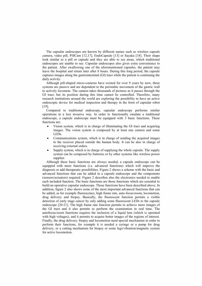
Although these basic functions are always needed, a capsule endoscope can be
equipped with more functions (i.e. advanced functions) which will improve the
diagnosis or add therapeutic possibilities. Figure 2 shows a scheme with the basic and
advanced functions that can be added in a capsule endoscope and the components
(sensors/actuators) required. Figure 2 describes also the electronics needed to enable
each included function. The basic functions are those functions which are essential to
build an operative capsular endoscope. Those functions have been described above. In
addition, figure 2 also shows some of the most important advanced functions that can
be added, as for example fluorescence, high frame rate, auto-focus/zoom, locomotion,
drug delivery and biopsy. Basically, the fluorescent function permits a visible
detection of early stage cancer by only adding some fluorescent LEDs to the capsule
endoscope [20-21]. The high frame rate function permits to achieve more images of
the GI tract and it also permits to perform the examination in real time. The
autofocus/zoom functions requires the inclusion of a liquid lens (which is operated
with high voltages), and it permits to acquire better images of the regions of interest.
Finally, the drug delivery, biopsy and locomotion need special mechanism in order to
perform their functions, for example it is needed a syringe or a pump for drug
delivery, or a cutting mechanism for biopsy or some legs/vibration/magnetic system
for active locomotion.
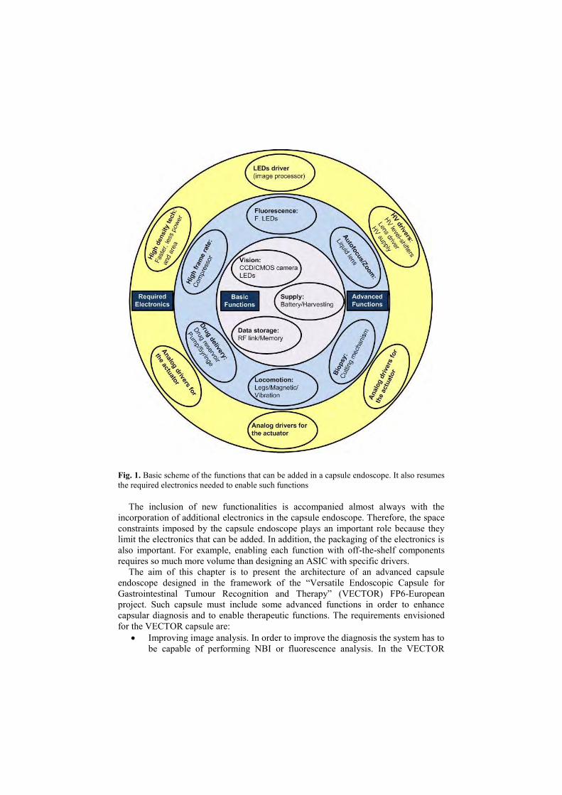
Fig. 1. Basic scheme of the functions that can be added in a capsule endoscope. It also resumes
the required electronics needed to enable such functions
The inclusion of new functionalities is accompanied almost always with the
incorporation of additional electronics in the capsule endoscope. Therefore, the space
constraints imposed by the capsule endoscope plays an important role because they
limit the electronics that can be added. In addition, the packaging of the electronics is
also important. For example, enabling each function with off-the-shelf components
requires so much more volume than designing an ASIC with specific drivers.
The aim of this chapter is to present the architecture of an advanced capsule
endoscope designed in the framework of the “Versatile Endoscopic Capsule for
Gastrointestinal Tumour Recognition and Therapy” (VECTOR) FP6-European
project. Such capsule must include some advanced functions in order to enhance
capsular diagnosis and to enable therapeutic functions. The requirements envisioned
for the VECTOR capsule are:
Improving image analysis. In order to improve the diagnosis the system has to
be capable of performing NBI or fluorescence analysis. In the VECTOR
capsule these different analysis are achieved by using different LEDs in each
case (e.g. for the Fluorescence function the capsule uses fluorescent LEDs).
Improving the vision system by enabling the autofocus and zoom function.
This is achieved by adding a liquid lens.
High frame-rate: the state-of-the art capsules have a low frame rate. By
increasing the frame rate the doctors are able to analyse more images. In order
to achieve a high frame-rate it is necessary to implement a compressor
between the camera and the transceiver.
Active locomotion. It permits to create space, stop and move forward and
backwards the capsule inside the GI tract. The movement can be achieved by
adding some legs to the VECTOR capsule or by using magnets.
Enabling therapeutic functions like drug delivery and/or biopsies.
Implementation of the above functions with off-the-shelf components requires
too much space. So, a specific solution in which a unique ASIC is used has been
performed.
2 System architecture
An active capsular endoscope needs the intervention of a medical doctor during the
exploration. Guiding of the capsule endoscope is necessary to explore in detail a
region or to do therapy. This procedure depends on the acquired images and the
criteria of the medical doctor, therefore the possibility of a human error have to be
considered. Nevertheless, if some robotic capabilities are added into the capsule
endoscope, the possibility of a human error can be highly reduced. For example, if the
robotic capsular endoscope also processes the images searching for polyps or
abnormalities. The robotic functions can be also very useful during navigation. Such
robotic functions can be enabled by adding a central processing unit (CPU), like a
microprocessor, into the capsule.
As the VECTOR project pursues the goal of improving capsular endoscopy by
adding advanced functions, enabling therapy and robotic behaviour, the basic and
essential blocks of the smart VECTOR capsule must be: powering unit, vision system,
telemetry system, locomotion system and a CPU. The powering, vision and telemetry
units are the basic functions for a passive capsular endoscope, however, for an active
capsule it is needed to add the locomotion function. The CPU is required to enable the
robotic behaviour of the capsular endoscope.
Due to the space limitations and the low power consumption requirements, it is
preferable to use ICs. For this reason, the trend for this system architecture is to unify
the CPU and the locomotive system in one ASIC (the control IC). With this system
architecture the robotic behaviour is enabled by software.
Figure 3 illustrates the concept of the VECTOR capsule. The ASIC, the CMOS
camera, the telemetry system and supply system are in charge of enabling the basic
functions of an active capsular endoscope. The ASIC includes the drivers needed to
enable advanced vision functions and locomotion. The selected actuator for enabling
locomotion in the VECTOR capsule is a brushless (BLDC) micromotor. The most
important feature of this actuator is that it can also be used to enable drug delivery
and biopsy functions. Therefore, with the inclusion of a BLDC motor driver into the
control ASIC it is possible to enable 3 different functions.
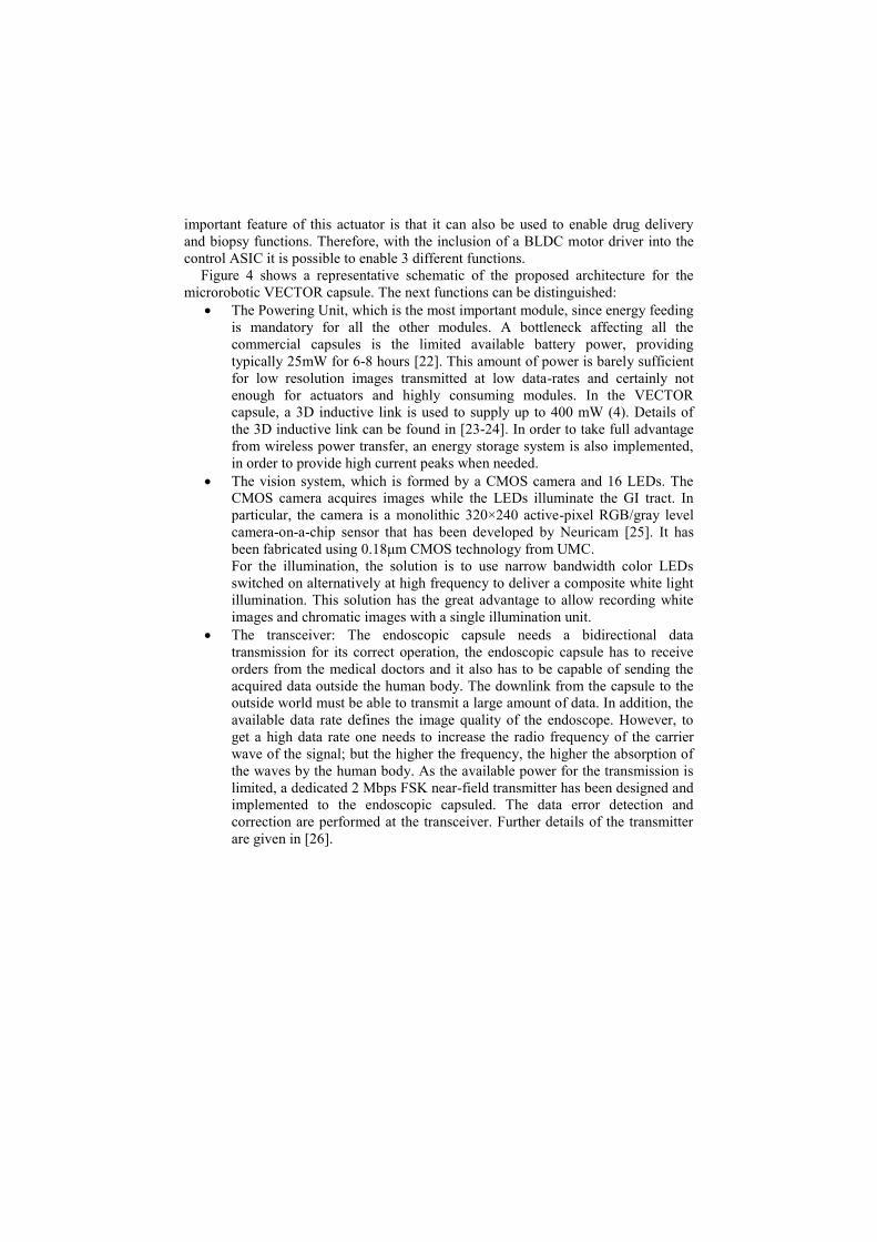
Figure 4 shows a representative schematic of the proposed architecture for the
microrobotic VECTOR capsule. The next functions can be distinguished:
The Powering Unit, which is the most important module, since energy feeding
is mandatory for all the other modules. A bottleneck affecting all the
commercial capsules is the limited available battery power, providing
typically 25mW for 6-8 hours [22]. This amount of power is barely sufficient
for low resolution images transmitted at low data-rates and certainly not
enough for actuators and highly consuming modules. In the VECTOR
capsule, a 3D inductive link is used to supply up to 400 mW (4). Details of
the 3D inductive link can be found in [23-24]. In order to take full advantage
from wireless power transfer, an energy storage system is also implemented,
in order to provide high current peaks when needed.
The vision system, which is formed by a CMOS camera and 16 LEDs. The
CMOS camera acquires images while the LEDs illuminate the GI tract. In
particular, the camera is a monolithic 320×240 active-pixel RGB/gray level
camera-on-a-chip sensor that has been developed by Neuricam [25]. It has
been fabricated using 0.18μm CMOS technology from UMC.
For the illumination, the solution is to use narrow bandwidth color LEDs
switched on alternatively at high frequency to deliver a composite white light
illumination. This solution has the great advantage to allow recording white
images and chromatic images with a single illumination unit.
The transceiver: The endoscopic capsule needs a bidirectional data
transmission for its correct operation, the endoscopic capsule has to receive
orders from the medical doctors and it also has to be capable of sending the
acquired data outside the human body. The downlink from the capsule to the
outside world must be able to transmit a large amount of data. In addition, the
available data rate defines the image quality of the endoscope. However, to
get a high data rate one needs to increase the radio frequency of the carrier
wave of the signal; but the higher the frequency, the higher the absorption of
the waves by the human body. As the available power for the transmission is
limited, a dedicated 2 Mbps FSK near-field transmitter has been designed and
implemented to the endoscopic capsuled. The data error detection and
correction are performed at the transceiver. Further details of the transmitter
are given in [26].
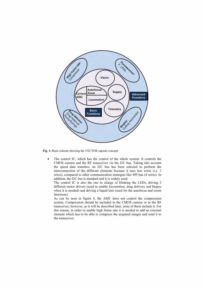
Fig. 3. Basic scheme showing the VECTOR capsule concept.
The control IC, which has the control of the whole system. It controls the
CMOS camera and the RF transceiver via the I2C bus. Taking into account
the speed data transfers, an I2C bus has been selected to perform the
interconnection of the different elements because it uses less wires (i.e. 2
wires), compared to other communication strategies like SPI bus (4 wires). In
addition, the I2C bus is standard and it is widely used.
The control IC is also the one in charge of blinking the LEDs, driving 2
different motor drivers (used to enable locomotion, drug delivery and biopsy
when it is needed) and driving a liquid lens (used for the autofocus and zoom
functions).
As can be seen in figure 4, the ASIC does not control the compression
system. Compression should be included in the CMOS camera or in the RF
transceiver, however, as it will be described later, none of them include it. For
this reason, in order to enable high frame rate it is needed to add an external
element which has to be able to compress the acquired images and send it to
the transceiver.
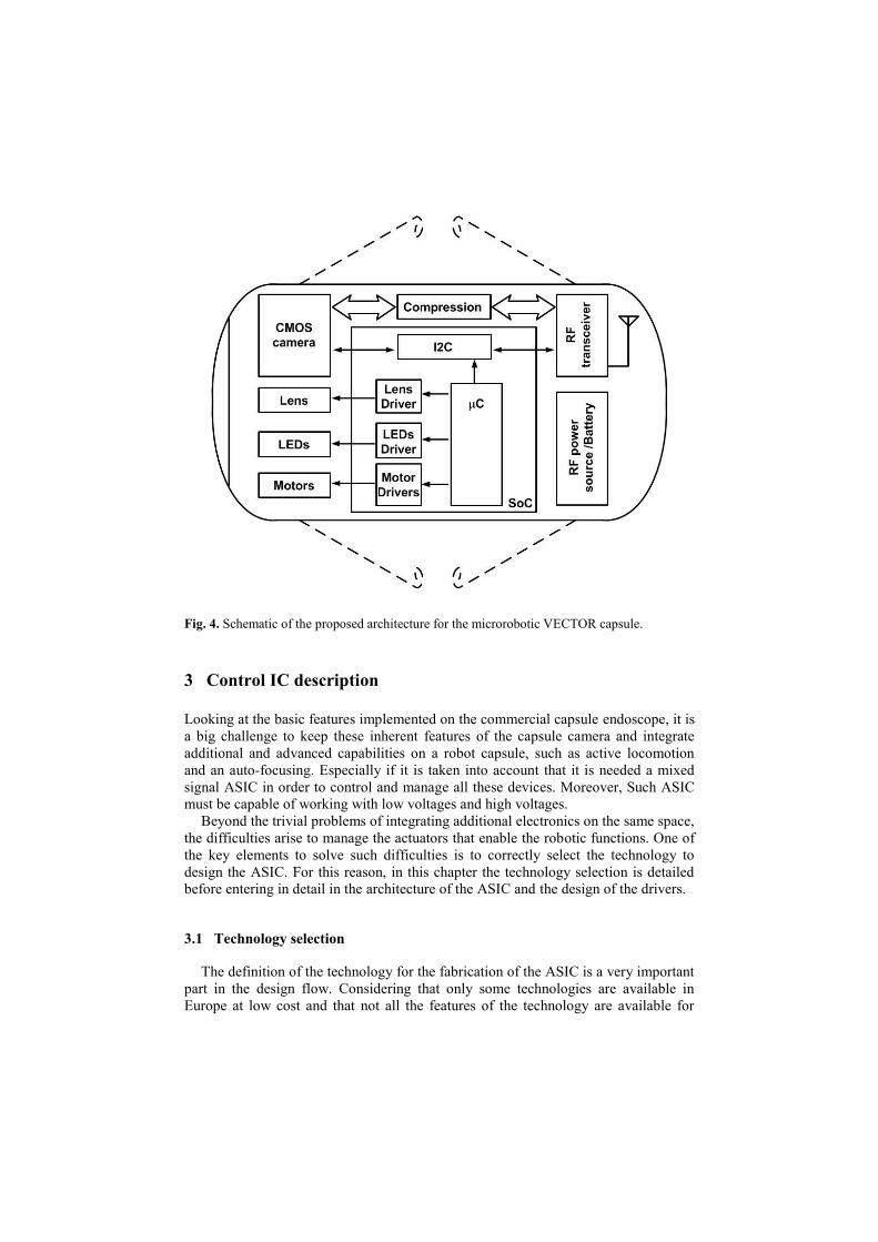
Fig. 4. Schematic of the proposed architecture for the microrobotic VECTOR capsule.
3 Control IC description
Looking at the basic features implemented on the commercial capsule endoscope, it is
a big challenge to keep these inherent features of the capsule camera and integrate
additional and advanced capabilities on a robot capsule, such as active locomotion
and an auto-focusing. Especially if it is taken into account that it is needed a mixed
signal ASIC in order to control and manage all these devices. Moreover, Such ASIC
must be capable of working with low voltages and high voltages.
Beyond the trivial problems of integrating additional electronics on the same space,
the difficulties arise to manage the actuators that enable the robotic functions. One of
the key elements to solve such difficulties is to correctly select the technology to
design the ASIC. For this reason, in this chapter the technology selection is detailed
before entering in detail in the architecture of the ASIC and the design of the drivers.
3.1 Technology selection
The definition of the technology for the fabrication of the ASIC is a very important
part in the design flow. Considering that only some technologies are available in
Europe at low cost and that not all the features of the technology are available for
low-volume users, the technology selection has to be done at the beginning of the
design flow.
To fabricate the ASIC several technologies have been evaluated. It has been taken
into account the integration density, the power consumption and the powering and
driving voltages required for the capsule elements. All the technologies evaluated are
available through Europractice Consortium or through Circuit Multi Projects (CMP)
which offer low cost fabrication through Multi-Project-Wafer (MPW). On Table 1
there is a summary of technologies which can be used to design the IC for the
VECTOR project. Deep-submicron technologies can not be used in VECTOR
because the high-voltage requirements.
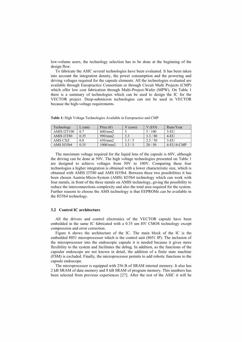
Table 1: High Voltage Technologies Available in Europractice and CMP
Technology L (um) Price (€) V (core) V (I/O) Runs/Year
AMIS I2T100 0.7 600/mm2 5 5 / 100 5-EU
AMIS I3T80 0.35 990/mm2 3.3 3.3 / 80 4-EU
AMS CXZ 0.8 650/mm2 3.3 / 5 2.5 / 50 3-EU
AMS H35b4 0.35 1000/mm2 3.3 / 5 20 / 50 4-EU/4-CMP
The maximum voltage required for the liquid lens of the capsule is 60V, although
the driving can be done at 50V. The high voltage technologies presented on Table 1
are designed to achieve voltages from 50V to 100V. Comparing these four
technologies a higher integration is obtained with a lower characteristic size, which is
obtained with AMIS I3T80 and AMS H35b4. Between these two possibilities it has
been chosen Austria-Micro-System (AMS) H35b4 technology which can work with
four metals, in front of the three metals on AMIS technology, giving the possibility to
reduce the interconnections complexity and also the total area required for the system.
Further reasons to choose the AMS technology is that EEPROMs can be available in
the H35b4 technology.
3.2 Control IC architecture
All the drivers and control electronics of the VECTOR capsule have been
embedded in the same IC fabricated with a 0.35 um HV CMOS technology except
compression and error correction.
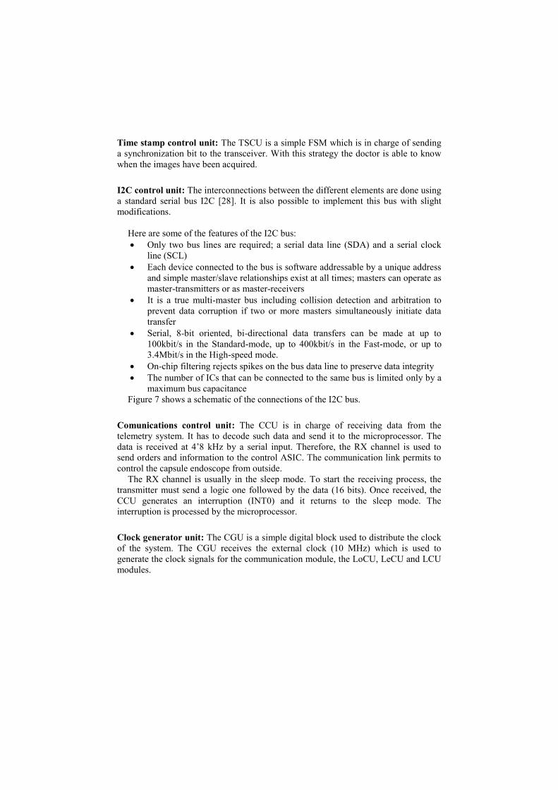
Figure 6 shows the architecture of the IC. The main block of the IC is the
embedded 8051 microprocessor which is the control unit (8051 IP). The inclusion of
the microprocessor into the endoscopic capsule it is needed because it gives more
flexibility to the system and facilitates the debug. In addition, as the functions of the
capsular endoscope are not known in detail, the addition of a finite state machine
(FSM) is excluded. Finally, the microprocessor permits to add robotic functions to the
capsule endoscope.
The microprocessor is equipped with 256 B of SRAM internal memory. It also has
2 kB SRAM of data memory and 8 kB SRAM of program memory. This numbers has
been selected from previous experiences [27]. After the test of the ASIC it will be
possible to exactly determine the amount of memory that is really needed. The
memory type used is volatile. Therefore, each time the VECTOR capsule is powered-
up, the program has to be uploaded in the program memory area. EEPROM memories
have not been selected because they are not available by the technology provider in
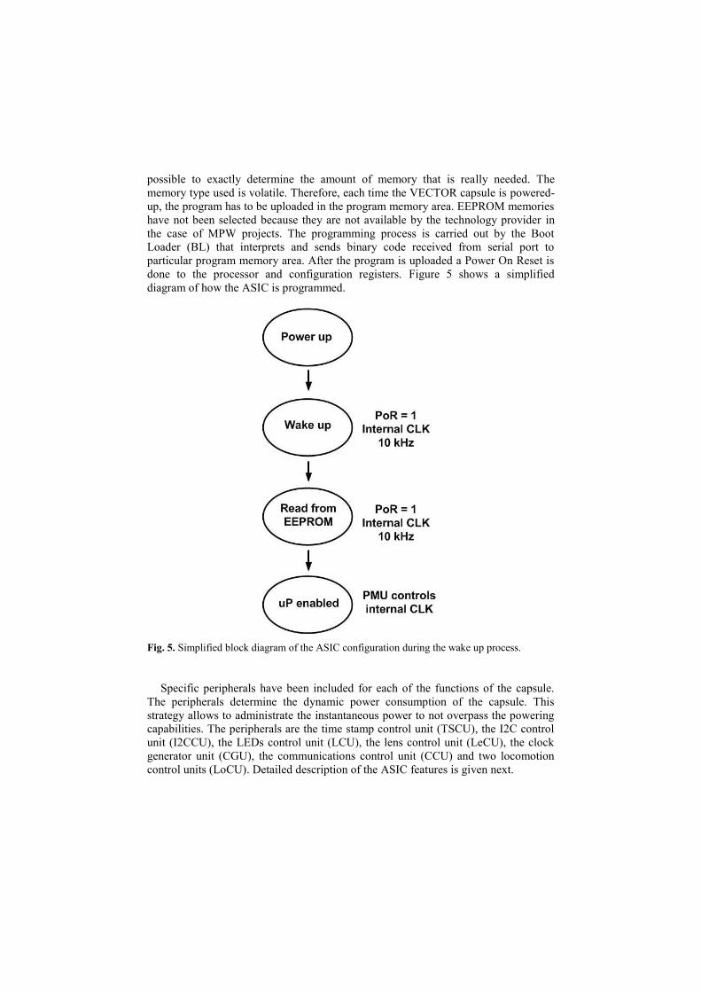
the case of MPW projects. The programming process is carried out by the Boot
Loader (BL) that interprets and sends binary code received from serial port to
particular program memory area. After the program is uploaded a Power On Reset is
done to the processor and configuration registers. Figure 5 shows a simplified
diagram of how the ASIC is programmed.
Fig. 5. Simplified block diagram of the ASIC configuration during the wake up process.
Specific peripherals have been included for each of the functions of the capsule.
The peripherals determine the dynamic power consumption of the capsule. This
strategy allows to administrate the instantaneous power to not overpass the powering
capabilities. The peripherals are the time stamp control unit (TSCU), the I2C control
unit (I2CCU), the LEDs control unit (LCU), the lens control unit (LeCU), the clock
generator unit (CGU), the communications control unit (CCU) and two locomotion
control units (LoCU). Detailed description of the ASIC features is given next.
Time stamp control unit: The TSCU is a simple FSM which is in charge of sending
a synchronization bit to the transceiver. With this strategy the doctor is able to know
when the images have been acquired.
I2C control unit: The interconnections between the different elements are done using
a standard serial bus I2C [28]. It is also possible to implement this bus with slight
modifications.
Here are some of the features of the I2C bus:
Only two bus lines are required; a serial data line (SDA) and a serial clock
line (SCL)
Each device connected to the bus is software addressable by a unique address
and simple master/slave relationships exist at all times; masters can operate as
master-transmitters or as master-receivers
It is a true multi-master bus including collision detection and arbitration to
prevent data corruption if two or more masters simultaneously initiate data
transfer
Serial, 8-bit oriented, bi-directional data transfers can be made at up to
100kbit/s in the Standard-mode, up to 400kbit/s in the Fast-mode, or up to
3.4Mbit/s in the High-speed mode.
On-chip filtering rejects spikes on the bus data line to preserve data integrity
The number of ICs that can be connected to the same bus is limited only by a
maximum bus capacitance
Figure 7 shows a schematic of the connections of the I2C bus.
Comunications control unit: The CCU is in charge of receiving data from the
telemetry system. It has to decode such data and send it to the microprocessor. The
data is received at 4’8 kHz by a serial input. Therefore, the RX channel is used to
send orders and information to the control ASIC. The communication link permits to
control the capsule endoscope from outside.
The RX channel is usually in the sleep mode. To start the receiving process, the
transmitter must send a logic one followed by the data (16 bits). Once received, the
CCU generates an interruption (INT0) and it returns to the sleep mode. The
interruption is processed by the microprocessor.
Clock generator unit: The CGU is a simple digital block used to distribute the clock
of the system. The CGU receives the external clock (10 MHz) which is used to
generate the clock signals for the communication module, the LoCU, LeCU and LCU
modules.
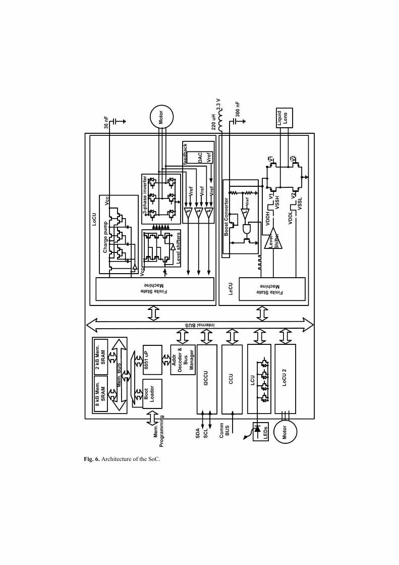
Fig. 6. Architecture of the SoC.
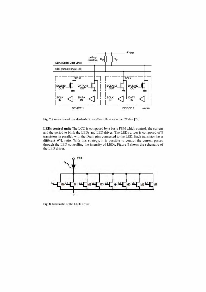
Fig. 7. Connection of Standard-AND Fast-Mode Devices to the I2C-bus [28].
LEDs control unit: The LCU is composed by a basic FSM which controls the current
and the period to blink the LEDs and LED driver. The LEDs driver is composed of 8
transistors in parallel, with the Drain pins connected to the LED. Each transistor has a
different W/L ratio. With this strategy, it is possible to control the current passes
through the LED controlling the intensity of LEDs. Figure 8 shows the schematic of
the LED driver.
Fig. 8. Schematic of the LEDs driver.
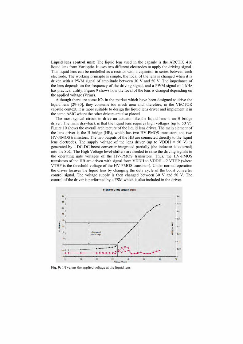
Liquid lens control unit: The liquid lens used in the capsule is the ARCTIC 416
liquid lens from Varioptic. It uses two different electrodes to apply the driving signal.
This liquid lens can be modelled as a resistor with a capacitor in series between each
electrode. The working principle is simple, the focal of the lens is changed when it is
driven with a PWM signal of amplitude between 30 V and 50 V. The impedance of
the lens depends on the frequency of the driving signal, and a PWM signal of 1 kHz
has practical utility. Figure 9 shows how the focal of the lens is changed depending on
the applied voltage (Vrms).
Although there are some ICs in the market which have been designed to drive the
liquid lens [29-30], they consume too much area and, therefore, in the VECTOR
capsule context, it is more suitable to design the liquid lens driver and implement it in
the same ASIC where the other drivers are also placed.
The most typical circuit to drive an actuator like the liquid lens is an H-bridge
driver. The main drawback is that the liquid lens requires high voltages (up to 50 V).
Figure 10 shows the overall architecture of the liquid lens driver. The main element of
the lens driver is the H-bridge (HB), which has two HV-PMOS transistors and two
HV-NMOS transistors. The two outputs of the HB are connected directly to the liquid
lens electrodes. The supply voltage of the lens driver (up to VDDH = 50 V) is
generated by a DC-DC boost converter integrated partially (the inductor is external)
into the SoC. The High Voltage level-shifters are needed to raise the driving signals to
the operating gate voltages of the HV-PMOS transistors. Thus, the HV-PMOS
transistors of the HB are driven with signal from VDDH to VDDH – 2 VTHP (where
VTHP is the threshold voltage of the HV-PMOS transistor). Under normal operation
the driver focuses the liquid lens by changing the duty cycle of the boost converter
control signal. The voltage supply is then changed between 30 V and 50 V. The
control of the driver is performed by a FSM which is also included in the driver.
Fig. 9: 1/f versus the applied voltage at the liquid lens.
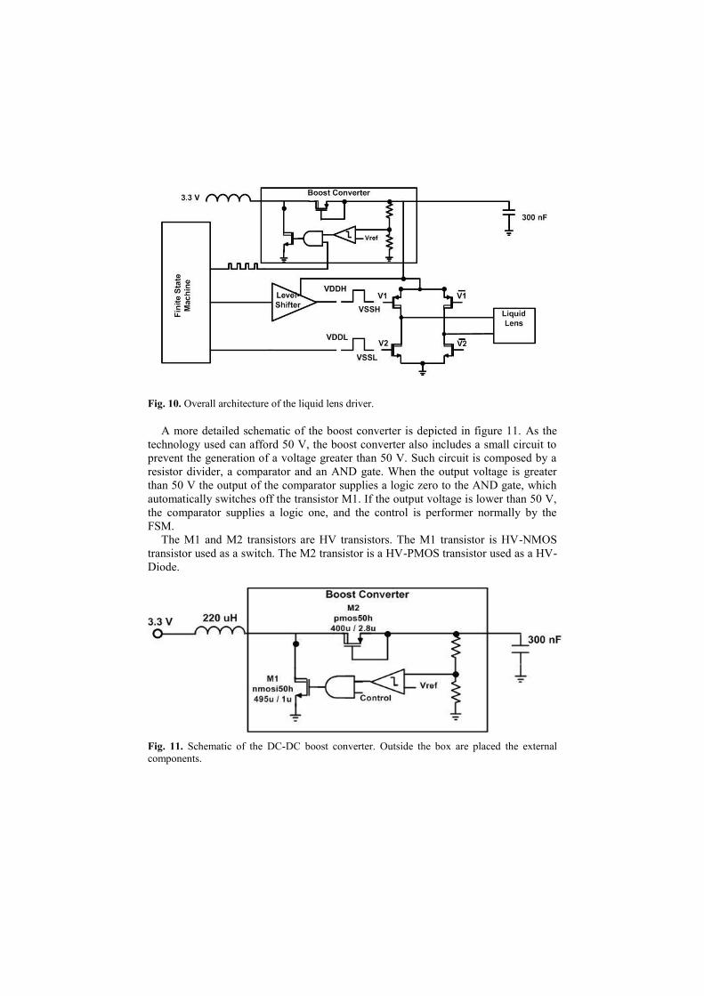
Fig. 10. Overall architecture of the liquid lens driver.
A more detailed schematic of the boost converter is depicted in figure 11. As the
technology used can afford 50 V, the boost converter also includes a small circuit to
prevent the generation of a voltage greater than 50 V. Such circuit is composed by a
resistor divider, a comparator and an AND gate. When the output voltage is greater
than 50 V the output of the comparator supplies a logic zero to the AND gate, which
automatically switches off the transistor M1. If the output voltage is lower than 50 V,
the comparator supplies a logic one, and the control is performer normally by the
FSM.
The M1 and M2 transistors are HV transistors. The M1 transistor is HV-NMOS
transistor used as a switch. The M2 transistor is a HV-PMOS transistor used as a HV-
Diode.
Fig. 11. Schematic of the DC-DC boost converter. Outside the box are placed the external
components.
Locomotion Control Unit: The micromotor to be used in the capsule endoscope is a
micro BLDC motor SBL04 (4mm diameter) from Namiki. It is a very attractive
solution for engineers working in micro technologies and medical field, servo lens
and micropumps. The strong construction allows the operation also in extreme
environmental conditions. In combination with planetary geared SPG04, 4 different
reduction ratios, the micro motor is suitable for a wide range of applications [31].
The driver of the Namiki motor is based on a 3-phase structure. This driver is the
most popular and simplest solution for the control of the BLDC motor. Figure 12
shows the driver composed by 6 MOSFETs and controlled by 6 different signals [32].
Usually the MOSFETs are accompanied with a schottky diode in anti-parallel in order
to manage the current generated in the inductance of the motor when one of the
driving transistors is switched-off. Basically, the diodes maintain the transistors in the
safe operating area (SOA). The better size reduction of the motor driver is achieved
eliminating this external component. Despite its simplicity, it is needed to pay
attention while designing the driver in order to minimize the gate voltage and the size
of the transistors and, more important, to avoid freewheeling currents in the chip [33].
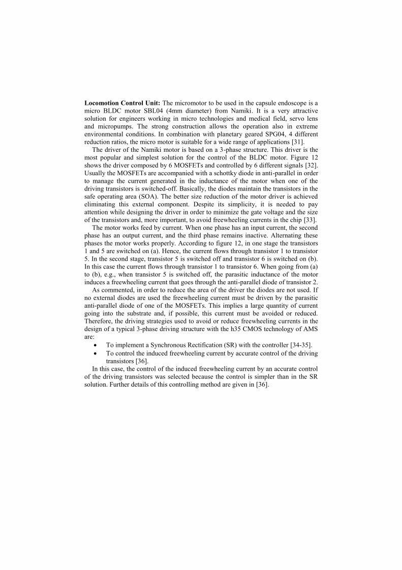
The motor works feed by current. When one phase has an input current, the second
phase has an output current, and the third phase remains inactive. Alternating these
phases the motor works properly. According to figure 12, in one stage the transistors
1 and 5 are switched on (a). Hence, the current flows through transistor 1 to transistor
5. In the second stage, transistor 5 is switched off and transistor 6 is switched on (b).
In this case the current flows through transistor 1 to transistor 6. When going from (a)
to (b), e.g., when transistor 5 is switched off, the parasitic inductance of the motor
induces a freewheeling current that goes through the anti-parallel diode of transistor 2.
As commented, in order to reduce the area of the driver the diodes are not used. If
no external diodes are used the freewheeling current must be driven by the parasitic
anti-parallel diode of one of the MOSFETs. This implies a large quantity of current
going into the substrate and, if possible, this current must be avoided or reduced.
Therefore, the driving strategies used to avoid or reduce freewheeling currents in the
design of a typical 3-phase driving structure with the h35 CMOS technology of AMS
are:
To implement a Synchronous Rectification (SR) with the controller [34-35].
To control the induced freewheeling current by accurate control of the driving
transistors [36].
In this case, the control of the induced freewheeling current by an accurate control
of the driving transistors was selected because the control is simpler than in the SR
solution. Further details of this controlling method are given in [36].
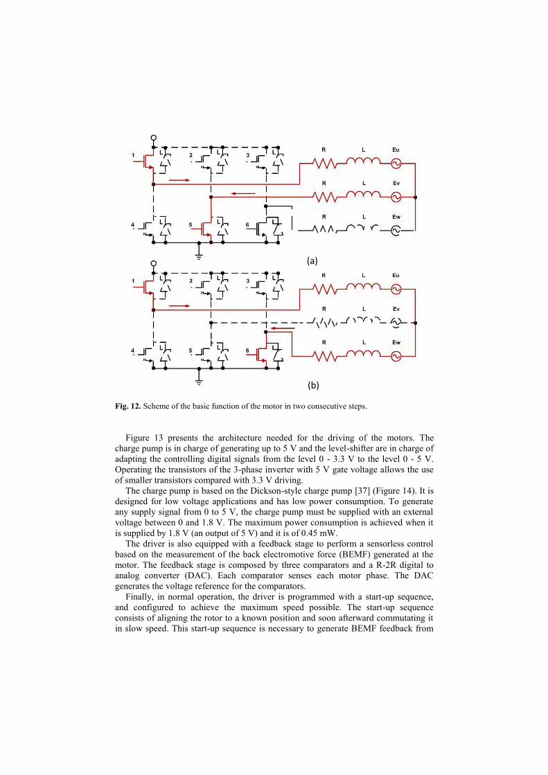
Fig. 12. Scheme of the basic function of the motor in two consecutive steps.
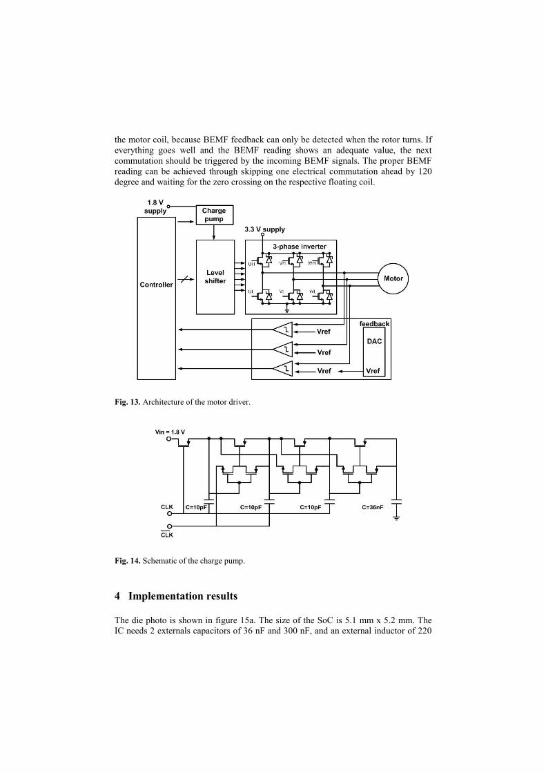
Figure 13 presents the architecture needed for the driving of the motors. The
charge pump is in charge of generating up to 5 V and the level-shifter are in charge of
adapting the controlling digital signals from the level 0 - 3.3 V to the level 0 - 5 V.
Operating the transistors of the 3-phase inverter with 5 V gate voltage allows the use
of smaller transistors compared with 3.3 V driving.
The charge pump is based on the Dickson-style charge pump [37] (Figure 14). It is
designed for low voltage applications and has low power consumption. To generate
any supply signal from 0 to 5 V, the charge pump must be supplied with an external
voltage between 0 and 1.8 V. The maximum power consumption is achieved when it
is supplied by 1.8 V (an output of 5 V) and it is of 0.45 mW.
The driver is also equipped with a feedback stage to perform a sensorless control
based on the measurement of the back electromotive force (BEMF) generated at the
motor. The feedback stage is composed by three comparators and a R-2R digital to
analog converter (DAC). Each comparator senses each motor phase. The DAC
generates the voltage reference for the comparators.
Finally, in normal operation, the driver is programmed with a start-up sequence,
and configured to achieve the maximum speed possible. The start-up sequence
consists of aligning the rotor to a known position and soon afterward commutating it
in slow speed. This start-up sequence is necessary to generate BEMF feedback from
(b)
(a)
the motor coil, because BEMF feedback can only be detected when the rotor turns. If
everything goes well and the BEMF reading shows an adequate value, the next
commutation should be triggered by the incoming BEMF signals. The proper BEMF
reading can be achieved through skipping one electrical commutation ahead by 120
degree and waiting for the zero crossing on the respective floating coil.
Fig. 13. Architecture of the motor driver.
Fig. 14. Schematic of the charge pump.
4 Implementation results
The die photo is shown in figure 15a. The size of the SoC is 5.1 mm x 5.2 mm. The
IC needs 2 externals capacitors of 36 nF and 300 nF, and an external inductor of 220
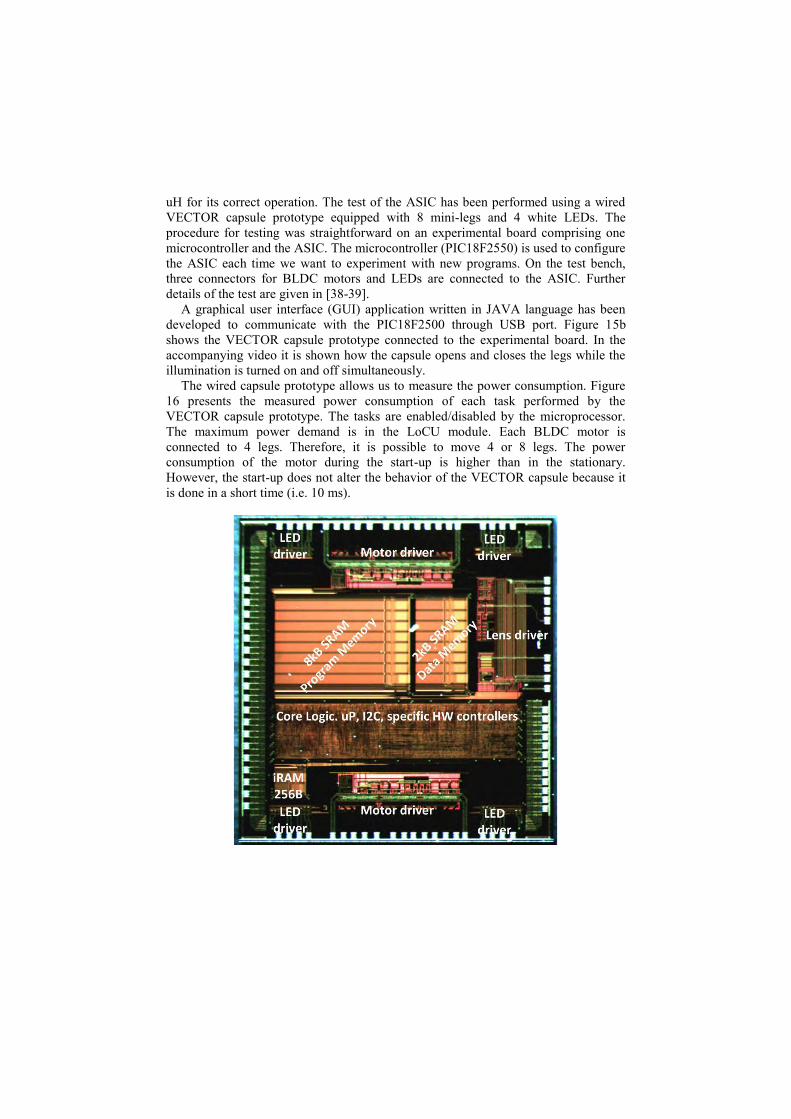
uH for its correct operation. The test of the ASIC has been performed using a wired
VECTOR capsule prototype equipped with 8 mini-legs and 4 white LEDs. The
procedure for testing was straightforward on an experimental board comprising one
microcontroller and the ASIC. The microcontroller (PIC18F2550) is used to configure
the ASIC each time we want to experiment with new programs. On the test bench,
three connectors for BLDC motors and LEDs are connected to the ASIC. Further
details of the test are given in [38-39].
A graphical user interface (GUI) application written in JAVA language has been
developed to communicate with the PIC18F2500 through USB port. Figure 15b
shows the VECTOR capsule prototype connected to the experimental board. In the
accompanying video it is shown how the capsule opens and closes the legs while the
illumination is turned on and off simultaneously.
The wired capsule prototype allows us to measure the power consumption. Figure
16 presents the measured power consumption of each task performed by the
VECTOR capsule prototype. The tasks are enabled/disabled by the microprocessor.
The maximum power demand is in the LoCU module. Each BLDC motor is
connected to 4 legs. Therefore, it is possible to move 4 or 8 legs. The power
consumption of the motor during the start-up is higher than in the stationary.
However, the start-up does not alter the behavior of the VECTOR capsule because it
is done in a short time (i.e. 10 ms).
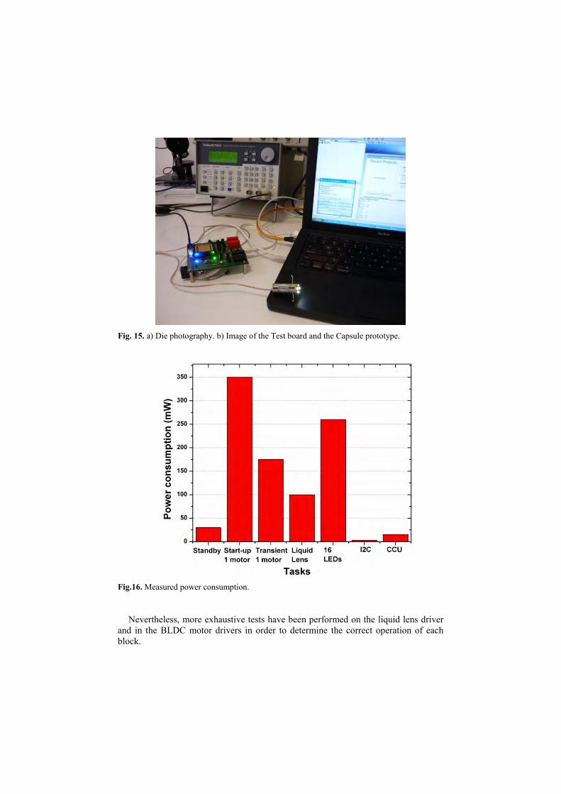
Fig. 15. a) Die photography. b) Image of the Test board and the Capsule prototype.
Fig.16. Measured power consumption.
Nevertheless, more exhaustive tests have been performed on the liquid lens driver
and in the BLDC motor drivers in order to determine the correct operation of each
block.
In the liquid lens driver the most problematic device is the boost converter, because
if it fails it is required to use an external high voltage generator, which cannot be
added in the capsule.
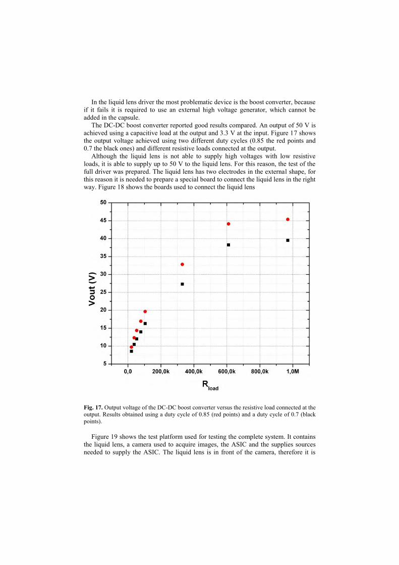
The DC-DC boost converter reported good results compared. An output of 50 V is
achieved using a capacitive load at the output and 3.3 V at the input. Figure 17 shows
the output voltage achieved using two different duty cycles (0.85 the red points and
0.7 the black ones) and different resistive loads connected at the output.
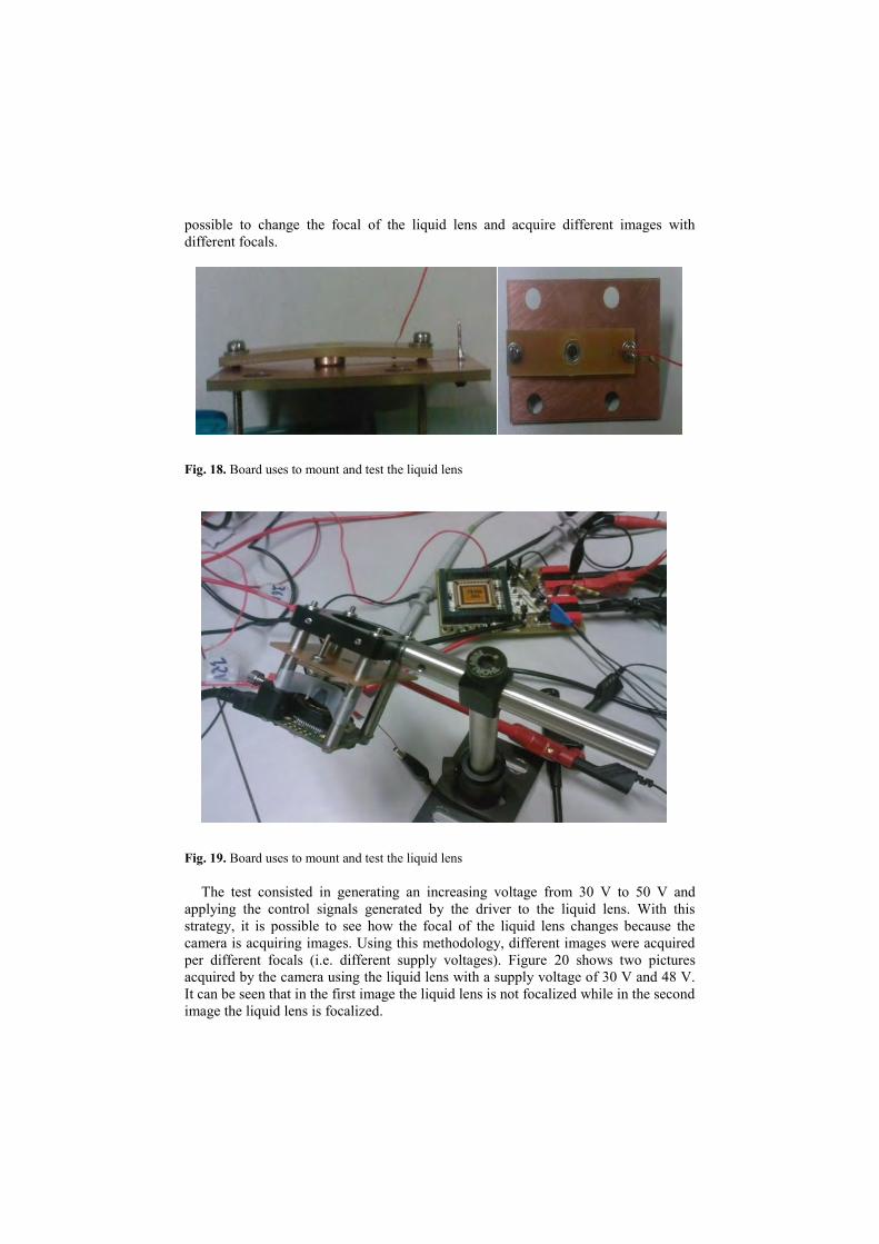
Although the liquid lens is not able to supply high voltages with low resistive
loads, it is able to supply up to 50 V to the liquid lens. For this reason, the test of the
full driver was prepared. The liquid lens has two electrodes in the external shape, for
this reason it is needed to prepare a special board to connect the liquid lens in the right
way. Figure 18 shows the boards used to connect the liquid lens
Fig. 17. Output voltage of the DC-DC boost converter versus the resistive load connected at the
output. Results obtained using a duty cycle of 0.85 (red points) and a duty cycle of 0.7 (black
points).
Figure 19 shows the test platform used for testing the complete system. It contains
the liquid lens, a camera used to acquire images, the ASIC and the supplies sources
needed to supply the ASIC. The liquid lens is in front of the camera, therefore it is
possible to change the focal of the liquid lens and acquire different images with
different focals.
Fig. 18. Board uses to mount and test the liquid lens
Fig. 19. Board uses to mount and test the liquid lens
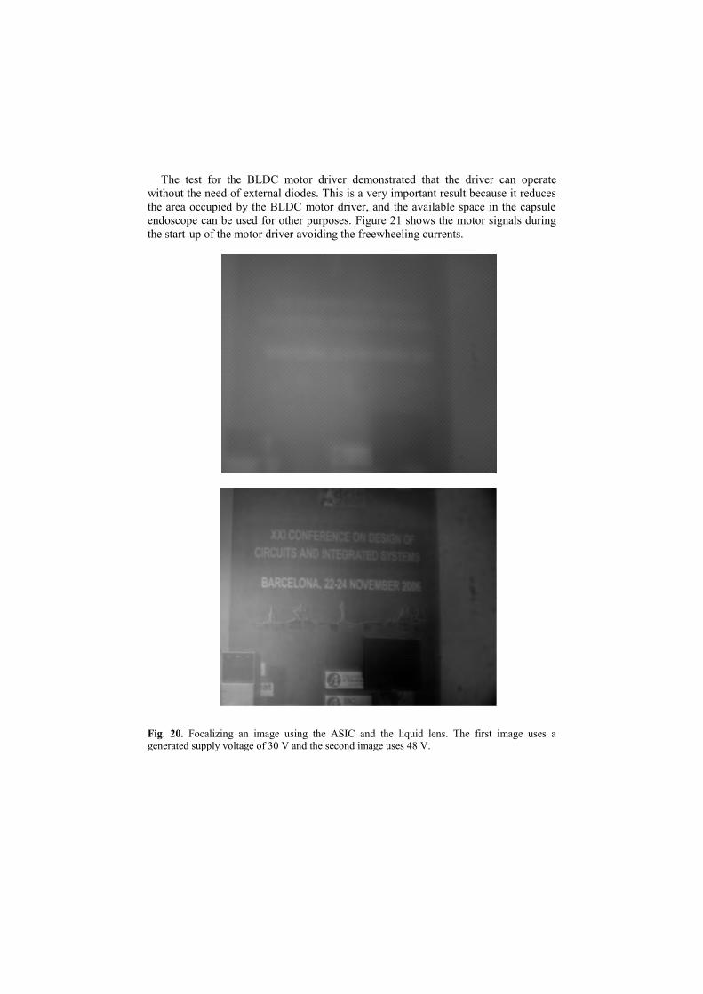
The test consisted in generating an increasing voltage from 30 V to 50 V and
applying the control signals generated by the driver to the liquid lens. With this
strategy, it is possible to see how the focal of the liquid lens changes because the
camera is acquiring images. Using this methodology, different images were acquired
per different focals (i.e. different supply voltages). Figure 20 shows two pictures
acquired by the camera using the liquid lens with a supply voltage of 30 V and 48 V.
It can be seen that in the first image the liquid lens is not focalized while in the second
image the liquid lens is focalized.
The test for the BLDC motor driver demonstrated that the driver can operate
without the need of external diodes. This is a very important result because it reduces
the area occupied by the BLDC motor driver, and the available space in the capsule
endoscope can be used for other purposes. Figure 21 shows the motor signals during
the start-up of the motor driver avoiding the freewheeling currents.
Fig. 20. Focalizing an image using the ASIC and the liquid lens. The first image uses a
generated supply voltage of 30 V and the second image uses 48 V.
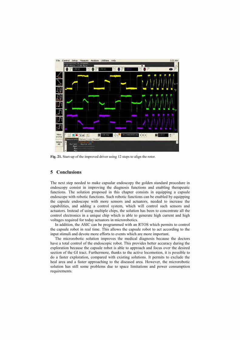
Fig. 21. Start-up of the improved driver using 12 steps to align the rotor.
5 Conclusions
The next step needed to make capsular endoscopy the golden standard procedure in
endoscopy consist in improving the diagnosis functions and enabling therapeutic
functions. The solution proposed in this chapter consists in equipping a capsule
endoscope with robotic functions. Such robotic functions can be enabled by equipping
the capsule endoscope with more sensors and actuators, needed to increase the
capabilities, and adding a control system, which will control such sensors and
actuators. Instead of using multiple chips, the solution has been to concentrate all the
control electronics in a unique chip which is able to generate high current and high
voltages required for today actuators in microrobotics.
In addition, the ASIC can be programmed with an RTOS which permits to control
the capsule robot in real time. This allows the capsule robot to act according to the
input stimuli and devote more efforts to events which are more important.
The microrobotic solution improves the medical diagnosis because the doctors
have a total control of the endoscopic robot. This provides better accuracy during the
exploration because the capsule robot is able to approach and focus over the desired
section of the GI tract. Furthermore, thanks to the active locomotion, it is possible to
do a faster exploration, compared with existing solutions. It permits to exclude the
heal area and a faster approaching to the diseased area. However, the microrobotic
solution has still some problems due to space limitations and power consumption
requirements.
Although miniaturization of sensors, actuators, control electronics, telemetry
system, wireless power system, compression system, CMOS camera and illumination
system is a fact, the inclusion of all these elements in an small capsule of reduced
dimension is still a challenge. In particular, for the presented microrobotic solution,
the size of the capsule robot is d 10mm and length 33 mm, which is bigger than the
state of the art capsule endoscopes. Furthermore, the addition of so many elements to
the capsule robot increases the power demand. Despite the fact that the wireless
power system is capable of supplying 400 mW, it is not enough power for the capsule
robot to perform more than one task simultaneously. Besides, the addition of the
compression to the presented capsular endoscope introduces a problem because it
cannot be integrated in the control IC due to the technology selection. It was finally
implemented in a small FPGA (silicon blue FPGA), however the best solution is to
integrate it in an IC specially devoted for this operation.
In conclusion, although the trend in capsular endoscopy is to equip the capsule
endoscope with robotic functions and increase diagnostic and therapeutic capabilities,
current limitations of space and power consumption makes this solution unfeasible at
the moment. For this reason, new solutions have to be applied.
References
1 Fujinon Endoscopic Systems 2003-07, http://www.fujinonendoscopy.com/
2 Diagnostic and Therapeutic Impact of Double-Balloon Enteroscopy (DBE) in a Series of
100 Patients with Suspected Small Bowel Diseases; Cazzato IA, Cammarota G, Nista EC,
Cesaro P, et al. Dig Liver Dis 2007 May;39(5):483-7.
3 Infection Control, and the Clinical Practice of Push Enteroscopy, Lawrence F.
Muscarella;“Endoscopic Shuffling, Gastroenterology Nursing, March/April 2007, Volume
30 Number 2 Pages:109-115.
4 Advances in colonic imaging: technical improvements in colonoscopy; Brown GJ, Saunders
BP; Eur J Gastroenterol Hepatol 2005; 17 (8):785-92.
5 Factors determining post-colonoscopy abdominal pain: prospective study of screening
colonoscopy in 1000 subjects; Lee YC, Wang HP, Chiu HM, Lin CP, Huang SP, Lai YP,
Wu MS, Chen MF, Lin JT , J Gastroenterol Hepatol 2006; 21 (10):1575-80.
6 Sedation-free colonoscopy using an upper endoscope is tolerable and effective in patients
with low body mass index: a prospective randomized study; Park CH, Lee WS, Joo YE,
Kim HS, Choi SK, Rew JS, Kim SJ , Am J Gastroenterol 2006; 101 (11):2504-10.
7 Colonoscopic polypectomy: a critical review of recent literature; Rubin PH, Waye JD , Curr
Gastroenterol Rep 2006; 8 (5):430-3.[
8 Complications of colonoscopy in an integrated health care delivery system; Levin TR, Zhao
W, Conell C, Seeff LC, Manninen DL, Shapiro JA, Schulman J, Ann Intern Med 2006; 145
(12):880-6.
9 Flexible sigmoidoscopy as a screening test for colorectal cancer; Janssens JF, Acta
Gastroenterol Belg 2005; 68 (2):248-9.
10 Does flexible small-diameter colonoscope reduce insertion pain during colonoscopy? Han
Y, Uno Y, Munakata A, World J Gastroenterol 2000; 6 (5):659-63.
11 Source SMIT – Society for Medical Innovation & Technology; presented at the SMIT
Congress 2005, Naples, Italy, Sept. 2005.
12 Wireless capsule endoscopy; Iddan G, Meron G, Glukhovsky A, Swain P, Nature 2000; 405
(6):417.
13 Olympus capsule endoscopy for small bowel examination, Gheorghe C,Iacob R,Bancila I., J
Gastrointestin Liver Dis 2007;16:309–313.
14 Small Bowel Obstruction from Capsule Endoscopy; Megan Boysen, MD; Michael Ritter,
MD , Western J Emerg Med. 2010;11(1):71-73.
15 ASGE Technology Status; Evaluation Report: wireless capsule endoscopy, Mishkin DS,
Chuttani R, Croffie J, et al., Gastrointest Endosc; 2006; 63(4):539-45.
16 Capsule endoscopy, Saurin JC., Endoscopy 2007;39:986-91.
17 Wireless Capsule Endoscopy, D. Adler, C. Gostout, Hospital Physician, pp. 14 – 22, 2003.
18 RF Systems Lab. Available at http://www.rfsystemlab.com
19 P. Glass, E. Cheung, H. Wang, R. Appasamy and M. Sitti; “A motorized anchoring
mechanism for a tethered capsule robot using fibrillar adhesives for interventions in the
esophagus”; Porc. IEEE International Conference on Biomedical Robotics and
Biomechatronics, 2008.
20 A fluorescence imaging device for endoscopic detection of early stage cancer – instrumental
and experimental studies. Baumgartner, R., et al 2008, Photochemistry and Photobiology,
Vol. 46, pp. 759–763. 10.1111/j.1751-1097.1987.tb04844.x.
21 Real-time endoscopic fluorescence imaging for early cancer detection in the gastrointestinal
tract. Zeng, H., et al., et al. 4, 1998, Bioimaging, Vol. 6, pp. 151–165. 10.1002/1361-6374.
22 The future of wireless capsule endoscopy. Swain, P. 14, 2008 : s.n., World J Gastroenterol ,
pp. 4142-4145.
23 A 3D Ferrite Coil Receiver for Wireless Power Supply of Endoscopic Capsules. Carta, R.,
Thoné, J. and Puers, R. 2009. Proceedings of the Eurosensors XXIII conference. Vol. 1, pp.
477-480. doi:10.1016/j.proche.2009.07.119. 1.
24 Wireless power supply as enabling technology towards active locomotion in capsular
endoscopy. R., Carta and et al. 2008. Proc. of Eurosensors XXII. pp. 1369-1372.
25 Neuricam. [Online] http://www.neuricam.com/.
26 Design of a 2 Mbps FSK near-field transmitter for wireless capsule endoscopy. Thoné, J.
and et al. 2009, Sens. Actuators A: Phys. . doi:10.1016/j.sna.2008.11.027..
27 Synopsys Inc. Guide to Design Ware DW8051 Macrocell Documentation. 2005.
28 Philips Semiconductors. 80C51 8-bit microcontroller family Datasheet. 2000.
29 HV895. [Online] [Cited: 2010 May 02.] http://www.supertex.com/Feature_HV895.html.
30 MAX14515. [Online] [Cited: 2010 May 02.] http://www.maxim-
ic.com/datasheet/index.mvp/id/5949.
31 expo21. expo21. [Online] [Cited: 11 March 2011.]
http://www.expo21xx.com/automation77/news/2094_robotics_equipment_namiki/news_def
ault.htm.
32 Permanent magnet brushless motor control techniques. Hui, T.S. and Basu, K.P. 2003. Proc.
of the National Power and Energy Conference. pp. 133-138.
33 Analysis of torque ripple in BLDC motor with commutation time. Kang, B., et al., et al.
2001. IEEE International Symposium on Industrial Electronics. Vol. 2, pp. 1044-1048.
34 Analysis of Electric Machines Piscataway. Krause, P.C., Wasynczuk, O. and Sudhoff, S.D.
1996, IEEE Press.
35 Smaller is better? [micromotors and electric drives]. Chapman, P.L. and Krein, P.T. 1, 2003,
IEEE Ind. Appl. Mag., Vol. 9, pp. 62-67.
36 Reducing torque ripple of brushless DC motor by varying input voltage . Nam, K., et al., et
al. IEEE Transactions on Magnetics . Vol. 42, pp. 1307–1310.
37 A new CMOS charge pump for low voltage applications . Ahmadi, M.M. and Jullien, G.
2005. IEEE International Symposium on Circuits and Systems. Vol. 5, pp. 4261-4264.

38 Control electronics integration toward endoscopic capsule robot performing legged
locomotion and illumination. Alonso, O., et al. 2010. IEEE/RSJ International Conference on
Intelligent Robots and Systems . pp. 2798–2803. doi: 10.1109/IROS.2010.5649283.
39 Enabling multiple robotic functions in an endoscopic capsule for the entire gastrointestinal
tract exploration. Alonso, O., et al. 2010. Proceedings of the ESSCIRC. pp. 386 –389. doi:
10.1109/ESSCIRC.2010.5619724.