Confined micro-explosion induced by ultrashort laser pulse at SiO2/Si interface
11
INVITED PAPER Confined micro-explosion induced by ultrashort laser pulse at SiO 2 /Si interface Ludovic Rapp • Bianca Haberl • Jodie E. Bradby • Eugene G. Gamaly • Jim S. Williams • Andrei V. Rode Received: 11 November 2013 / Accepted: 12 November 2013 / Published online: 30 November 2013 Ó Springer-Verlag Berlin Heidelberg 2013 Abstract Ultrashort laser pulses tightly focused inside a transparent material present an example of laser interaction with matter where all the laser-affected material remains inside the bulk, thus the mass is conserved. In this paper, we present the case where the high intensity of a laser pulse is above the threshold for optical breakdown, and the material is ionised in the focal area. We consider in detail a special case where a micro-explosion is formed at the boundary of a silicon surface buried under a 10-micron- thick oxidised layer, providing the opportunity to affect the silicon crystal by a strong shock wave and creating new material phases from the plasma state. We summarise the main conclusions on ultrafast laser-induced material mod- ifications in confined geometry and discuss the prospects of confined micro-explosion for forming new silicon phases. 1 Introduction Ultrashort laser pulse tightly focused inside the bulk of a transparent solid can easily generate MJ/cm 3 energy den- sity with the energy per pulse around a lJ within a focal volume less than a cubic micron. The pressure in the order of several TPa (1 TPa = 10 Mbar) inside a focal volume that is higher then the strength of any solid transforms a material to the plasma state, and then leads to the formation of a cavity (void) surrounded by a shell of compressed material. These features of the phenomenon delineate the areas of potential applications. The first area relates to the formation of different 3D structures, such as photonic crystals, waveguides, and gratings, by making use of multiple voids, separated or interconnected. For these studies the most important part is the process of void for- mation. To produce a void one has to generate a pressure in excess of the strength (the modulus) of a material. The second area of research relates to the studies of material transformations under high pressure–temperature condi- tions in the focal zone created on the laboratory’s tabletop. The interaction of a laser with matter at an intensity above the ionisation and ablation threshold proceeds in a similar way for all the materials. The solid converts into plasma in a few femtoseconds at the very beginning of the pulse, changing the interaction to the laser–plasma mode, increasing the absorption coefficient and reducing the absorption length, which ensures fast energy release in a very small volume. A strong shock wave generated in the interaction region propagates into the surrounding cold material. The shock wave propagation is accompanied by the compression of the solid material at the wave front and decompression behind it, leading to the formation of a void inside the material. The laser and shock wave-affected material is confined in the shell that surrounds the void. This shell is the major object for studies of new phases formation in the strongly non-equilibrium conditions of confined micro-explosions. Single pulse action thereby allows a formation of various three-dimensional structures inside a transparent solid in a controllable and predictable way. The first notion that the extreme conditions produced in the ultrafast laser-driven confined micro-explosion may L. Rapp E. G. Gamaly A. V. Rode (&) Laser Physics Centre, Research School of Physics and Engineering, The Australian National University, Canberra, ACT 0200, Australia e-mail: [email protected] B. Haberl J. E. Bradby J. S. Williams Electronic Materials Engineering, Research School of Physics and Engineering, The Australian National University, Canberra, ACT 0200, Australia 123 Appl. Phys. A (2014) 114:33–43 DOI 10.1007/s00339-013-8161-x
-
Upload
independent -
Category
Documents
-
view
7 -
download
0
Transcript of Confined micro-explosion induced by ultrashort laser pulse at SiO2/Si interface

INVITED PAPER
Confined micro-explosion induced by ultrashort laser pulseat SiO2/Si interface
Ludovic Rapp • Bianca Haberl • Jodie E. Bradby •
Eugene G. Gamaly • Jim S. Williams •
Andrei V. Rode
Received: 11 November 2013 / Accepted: 12 November 2013 / Published online: 30 November 2013
� Springer-Verlag Berlin Heidelberg 2013
Abstract Ultrashort laser pulses tightly focused inside a
transparent material present an example of laser interaction
with matter where all the laser-affected material remains
inside the bulk, thus the mass is conserved. In this paper,
we present the case where the high intensity of a laser pulse
is above the threshold for optical breakdown, and the
material is ionised in the focal area. We consider in detail a
special case where a micro-explosion is formed at the
boundary of a silicon surface buried under a 10-micron-
thick oxidised layer, providing the opportunity to affect the
silicon crystal by a strong shock wave and creating new
material phases from the plasma state. We summarise the
main conclusions on ultrafast laser-induced material mod-
ifications in confined geometry and discuss the prospects of
confined micro-explosion for forming new silicon phases.
1 Introduction
Ultrashort laser pulse tightly focused inside the bulk of a
transparent solid can easily generate MJ/cm3 energy den-
sity with the energy per pulse around a lJ within a focal
volume less than a cubic micron. The pressure in the order
of several TPa (1 TPa = 10 Mbar) inside a focal volume
that is higher then the strength of any solid transforms a
material to the plasma state, and then leads to the formation
of a cavity (void) surrounded by a shell of compressed
material. These features of the phenomenon delineate the
areas of potential applications. The first area relates to the
formation of different 3D structures, such as photonic
crystals, waveguides, and gratings, by making use of
multiple voids, separated or interconnected. For these
studies the most important part is the process of void for-
mation. To produce a void one has to generate a pressure in
excess of the strength (the modulus) of a material. The
second area of research relates to the studies of material
transformations under high pressure–temperature condi-
tions in the focal zone created on the laboratory’s tabletop.
The interaction of a laser with matter at an intensity above
the ionisation and ablation threshold proceeds in a similar
way for all the materials. The solid converts into plasma in
a few femtoseconds at the very beginning of the pulse,
changing the interaction to the laser–plasma mode,
increasing the absorption coefficient and reducing the
absorption length, which ensures fast energy release in a
very small volume. A strong shock wave generated in the
interaction region propagates into the surrounding cold
material. The shock wave propagation is accompanied by
the compression of the solid material at the wave front and
decompression behind it, leading to the formation of a void
inside the material. The laser and shock wave-affected
material is confined in the shell that surrounds the void.
This shell is the major object for studies of new phases
formation in the strongly non-equilibrium conditions of
confined micro-explosions. Single pulse action thereby
allows a formation of various three-dimensional structures
inside a transparent solid in a controllable and predictable
way.
The first notion that the extreme conditions produced in
the ultrafast laser-driven confined micro-explosion may
L. Rapp � E. G. Gamaly � A. V. Rode (&)
Laser Physics Centre, Research School of Physics and
Engineering, The Australian National University, Canberra,
ACT 0200, Australia
e-mail: [email protected]
B. Haberl � J. E. Bradby � J. S. Williams
Electronic Materials Engineering, Research School of Physics
and Engineering, The Australian National University, Canberra,
ACT 0200, Australia
123
Appl. Phys. A (2014) 114:33–43
DOI 10.1007/s00339-013-8161-x
serve as a novel microscopic laboratory for high pressure
and temperature studies, well beyond the levels achieved in
diamond anvil cell (DAC), was presented by Glezer and
Mazur in 1997 [1]. Recently, it was experimentally dem-
onstrated that it was possible to create super-high pressure
and temperature conditions in tabletop laboratory experi-
ments with ultrashort laser pulses focused inside transpar-
ent materials to the level significantly above the threshold
for optical breakdown [2–4]. The laser energy absorbed in
a sub-micron volume confined inside a bulk of pristine
solid is fully converted into internal energy. Therefore,
high energy density, several times higher than the strength
of any material, can be achieved with *100 fs, 1 lJ laser
pulses focused down to a 1 lm3 volume inside the solid.
Let us first underline the differences between the intense
laser–matter interaction at the surface of a solid and the
case when an interaction is confined deep inside a solid by
comparing the pressure created in the absorption region at
the same intensity and total absorbed energy. In the case of
laser–surface interactions, the pressure at the ablated
plume–solid interface equals the sum of the thermal pres-
sure of the plasma next to the boundary plus the pressure
from the recoil momentum of the expanding plasma. A
significant part of absorbed energy is spent on the expan-
sion and heating of the plume. Therefore, the ablation
pressure in the case of surface interactions depends on the
absorbed intensity by the power law Pabl / Imabs; m\1. In
the case of confined interactions (no expansion), the
maximum pressure is proportional to the absorbed intensity
Pconf / Iabs and it is almost twice as large as in the surface
interaction mode. Full description of the laser–matter
interaction processes and laser-induced material modifica-
tion from first principles embraces the self-consistent set of
equations that includes Maxwell’s equations for the laser
field coupling with matter, complemented with the equa-
tions describing the evolution of energy distribution func-
tions for electrons and phonons (ions) and the ionisation
state. A resolution of such a system of equations is a for-
midable task even for modern supercomputers. Therefore,
thorough analytical analysis is needed. We split this com-
plicated problem into a sequence of simpler interconnected
problems: the absorption of laser light, the ionisation and
energy transfer from electrons to ions, the heat conduction
and hydrodynamic expansion.
2 Energy density in confined ultrashort laser
interaction with solids
The sequence of processes in the ultrashort laser-induced
micro-explosion is the following. First the energy absorb-
ing plasma layer inside the focal area is formed during the
pulse time (100–200 fs). Then, hydrodynamics develops
with shock/rarefaction waves (*1 ps –100 ps) accompa-
nied by the formation of a void surrounded by a dense shell
(*100 ps –1 ns). In the following section, we consider the
major mechanisms of laser ionisation and absorption fol-
lowed by hydrodynamics in a confined geometry.
2.1 Absorbed energy density
The laser pulse with *100 nJ of energy focused into the
area Sfoc / k2 *10-8 cm2 delivers an energy density in
excess of 10 J/cm2, well above the ionisation and ablation
thresholds for any material [5]. Thus, the pressure level
above the strength of any material can be created in a
plasma layer of a typical thickness from 30 nm to 60 nm.
The absorbed laser energy per unit time and per unit vol-
ume during the pulse reads:
dEabs
dt¼ 2A
labs
I r; z; tð Þ ð1Þ
The electric field exponentially decays inside a plasma
layer, E ¼ E0exp �x=labsð Þ. Here, labs ¼ c=xk, A is the
Fresnel absorption coefficient [6]:
A ¼ 4n
ðnþ 1Þ2 þ k2¼ 2e00
j1þ e1=2j2kð2Þ
where e = ere ? ieim = (n ? ik)2 = (n2 - k2) ? i2nk; e is
the dielectric function, n and k are real and imaginary parts
of the complex refractive index.
The duration of an ultrashort pulse by definition is shorter
than the electron–phonon and electron–ion collision times
(typically *100 fs). We denote the energy per single elec-
tron by ee. Then the electron energy density change reads:
dðne eeÞdt
¼ 2A
labs
IðtÞ: ð3Þ
It has been shown [2–5] that electrons in these
conditions could be treated as ideal gas. Thus the
electron temperature to the end of the pulse is estimated
as the following:
Te �2A
1:5kB ne labs
IðtÞ t: ð4Þ
The electron temperature rises to tens of electron volts at
the very beginning of the pulse. Fast ionisation of a solid
occurs affecting absorption coefficient and absorption length.
We introduce below the optical properties dependent on the
changing electron density and electron energy.
2.2 Ionisation processes
Analytical estimates of the breakdown threshold, ionisation
rates and transient number density of electrons created in the
absorption region, based on previous studies [2–5], allow one
34 L. Rapp et al.
123

to obtain the general picture of the processes in qualitative
and quantitative agreement with computer simulations.
2.2.1 Ionisation thresholds
It was generally accepted that the breakdown of dielectrics
occurs when the number density of electrons in the con-
duction band reaches the critical density, nthe � nc ¼
me x2=4p e2 (x is the laser frequency). Recently, it was
proved that the exact threshold condition occurs at the
transformation of the travelling laser wave into an eva-
nescent wave, which results in nthe � e0nc (e0 is the initial
dielectric permittivity of material). Thus, laser parameters,
(intensity, wavelength, pulse duration) and material
parameters (band-gap width and electron–phonon effective
collision rate) at the breakdown threshold are linked
together by the condition, nthe � e0nc.
We stress that the ionisation threshold is the integral
characteristic dependent on the fluence and not on the
instantaneous maximum value of the intensity. For the
majority of transparent dielectrics, the ionisation threshold
fluence is around 2 J/cm2. It was determined that the ion-
isation threshold in fused silica is reached at the intensity
2 9 1013 W/cm2 at the end of a 100 fs pulse at 800 nm [7,
8]. Similar breakdown thresholds in the range of
(2.8 ± 1) 9 1013 W/cm2 were measured for the interac-
tion of a 120 fs, 620 nm laser with glass, MgF2, sapphire
and fused silica [9]. A weak dependence of the threshold
fluence on pulse duration was established. For example, for
fused silica the following threshold fluencies were deter-
mined: *2 J/cm2 at 1053 nm 300 fs; *1 J/cm2 at 526 nm
200 fs [10]; 1.2 J/cm2 (620 nm; *120 fs) [9]; 2.25 J/cm2
at 780 nm 220 fs [11, 12]; and 3 J/cm2 at 800 nm
10–100 fs [13].
The conduction band electrons gain energy in an intense
short pulse much faster than they transfer energy to the
lattice. Therefore, the actual structural damage (breaking
inter-atomic bonds) occurs after the electron-to-lattice
energy transfer, usually after the end of the pulse.
2.2.2 Multi-photon ionisation rate
Multi-photon ionisation has no intensity threshold and
hence creates the seed electrons at low intensities, n0, which
then multiplies by the electron impact ionisation process. A
reasonable estimate of the multi-photon ionisation proba-
bility (per atom, per second) is the following [14]:
wmpi � x n3=2ph
eosc
2 Dgap
� �nph
; ð5Þ
here nph ¼ Dgap
��hx is the number of photons necessary for
an electron to be transferred from the valence to the
conductivity band. At high intensity, the contribution of
electron impact processes becomes crucially important: at
wmpi–wimp the seed electrons are generated by multi-photon
effect, whilst final growth is due to the avalanche ionisa-
tion. Such an interplay of two mechanisms has been
demonstrated with the direct numerical solution of the
kinetic Fokker–Planck equation [14]. Under the condition
eosc = Dgap, �hx = 1.55 eV, nph ¼ Dgap
��hx * 6.4, and
x ¼ 2:356� 1015s�1, the multi-photon rate comprises
wmpi *5.95 9 1015 s-1. The ionisation time is estimated
as tion � w�1mpi. Thus, the ionisation threshold is reached in a
few femtoseconds at the beginning of a 100-fs pulse. After
that, the interaction proceeds in a laser–plasma interaction
mode.
2.2.3 Electron impact ionisation rates
Few electrons seeded by the multi-photon process oscillate
in the laser electromagnetic field and can be gradually
accelerated to the energy in excess of the band-gap. Elec-
trons with ee [ Dgap collide with electrons in the valence
band and can transfer sufficient energy to excite them into
the conduction band. Thus the number of free electrons
increases, which provokes the effect of avalanche ionisa-
tion. The probability of such an event per unit time (ioni-
sation rate) can be estimated as follows:
wimp �1
Dgap
dee
dt¼ 2eosc
Dgap
x2 meff
ðm2eff þ x2Þ /
I � meff
ðm2eff þ x2Þ : ð6Þ
Analysis shows that in the beginning of the ionisation
process the condition holds, x [ me�ph. The impact
ionisation rate expresses as, wimp � 2me�ph*1014–
1015 s-1. At the intensity maximum, the collision rate
reaches its maximum, x\me�i � xpe, and then the
ionisation rate equals to wimp � 2x2=me�i � 2x2=
xpe *5 9 1014 s-1 competing and exceeding the multi-
photon rate.
The qualitative estimates based on Eq. (6) are in
agreement with the Monte Carlo solutions to the Boltz-
mann kinetic equation for electrons [15].
2.2.4 Ionisation state during the laser pulse
To estimate the electron number density generated by
ionisation during the laser pulse, the recombination pro-
cesses should be taken into account. Electron recombina-
tion proceeds in a dense plasma mainly by three-body
Coulomb collisions with one of the electrons acting as a
third body [16]. The quantitative analysis performed in [4]
shows that in the solid density plasma, three-body recom-
bination leads fast to establishing the ionisation equilib-
rium when the ionisation rate is balanced by
Confined micro-explosion induced by ultrashort laser pulse 35
123

recombination. In these conditions, multiple ionisations
take place producing ions with charge Z [ 1. The electron
number density at the end of the pulse can be estimated in a
stationary approximation as follows: n2e � wion=Zbe (here,
be is the three-body recombination rate from [16]). Taking
wion* 1015 s-1; ee * 30 eV; Z = 5; lnK *2, one obtains
that the number density of electrons at the end of the pulse
becomes comparable to the atomic number density
ne * 1023 cm-3.
2.3 Increase in the absorbed energy density due
to modification of optical properties
Thus, to the end of the pulse, the electron number density
becomes comparable to the atomic number density and the
electron–ion collision rate reaches its maximum equalling
the plasma frequency. The optical properties of this tran-
sient plasma are described by Drude-like dielectric per-
mittivity depending on the electron density and
temperature. Let us estimate the absorption coefficient and
absorption length at the end of the pulse. The dielectric
function and refractive index in the beginning of the laser
pulse when me�i � xpe [ [x are estimated as the
following:
ere �x2
x2pe
; eim �xpe
x; n � k ¼ eim
2
� �1=2
: ð7Þ
For example, after the optical breakdown of fused silica
glass induced by an 800 nm laser (x = 4.7 9 1015 s-1;
xpe = 1.45 9 1016 s-1), the real and imaginary parts of
refractive index are n * k = 1.18, the absorption length of
ls = 54 nm, and the absorption coefficient A = 0.77 [4].
Therefore, the ionisation and heating convert silica into
plasma by reducing the energy deposition volume by up to
two orders of magnitude when compared with the focal
volume, and massively increasing the maximum pressure
in the absorption region. As a first approximation, the
energy absorption volume is taken as the focal area
multiplied by the absorption length. For the interaction
parameters presented above (I = 1014 W/cm2; A = 0.77;
ls = 54 nm; tp = 150 fs), the pressure corresponding to the
absorbed energy density equals to 4.4 TPa, ten times higher
than the Young modulus of sapphire, one of the hardest of
dielectrics. The general approach presented above is
applicable for estimating parameters of any wide band-
gap dielectric affected by a high-intensity short pulse laser.
2.4 Energy transfer from electrons to ions: relaxation
processes after the pulse
The hydrodynamic motion starts after the electrons transfer
the absorbed energy to the ions. The major processes
responsible for the energy transfer from electrons to ions
are electron–ion Coulomb collisions and electronic heat
conduction [4]. Below, the energy transfer times for dif-
ferent processes are presented.
The maximum value for the electron–ion momentum
exchange rate in the non-ideal plasma of confined micro-
explosion approximately equals the plasma frequency,
mei � xpe *3 9 1016 s-1 [8, 17–19]. Hence electrons in
ionised fused silica transfer their energy to ions over a time
of tenei � men
ei
� ��1� Mi=memeið Þ * (1–2) ps [8, 17–19].
The electro energy at the end of the pulse is much higher
then the ionisation potential. Therefore, ionisation by the
electron impact continues after the pulse ends [4, 16].
Losses in ionisation lead to temporary decrease in the
electron temperature and in the total pressure [4]. However,
fast recombination results in an increase in the ionic
pressure.
Energy transfer by non-linear electronic heat conduction
starts immediately after energy absorption. The heat wave
propagates outside of the heated area before the shock
wave emerges. The thermal diffusion coefficient is defined
conventionally as the following, D ¼ le ve=3 ¼ v2e
�3 mei,
where le, ve and nei are the electron mean free path, the
electron velocity and the momentum transfer rate, respec-
tively. The characteristic cooling time is conventionally
defined as tcool ¼ l2s
�D. For the conditions of the experi-
ments [2] nei–xpe *3 9 1016 s-1, ee = 50 eV, and the
cooling time is tcool ¼ 3 xpe me l2abs
�2ee = 14.9 ps.
Summing up, one concludes that the electrons transfer
energy to ions on approximately picosecond timescales.
The thermal ionisation and recombination are in a balance
after the end of the pulse permitting the description of the
plasma state by the Saha equations. The electronic non-
linear heat conduction becomes important in the first
*15 ps after the pulse and dominates the return to the
ambient conditions.
3 Shock wave propagation and void formation
It was shown above that focal volumes as small as 0.2 lm3
can be illuminated by focusing 800 nm laser pulses in the
bulk of fused silica glass (n = 1.453) with a microscope
objective with NA = 1.35 [2, 3]. The original focal volume
shrinks to much smaller energy deposition regions due to a
fast decrease in the absorption length, approximately five
times less than the averaged focal radius. The modified
shape of the absorption region is unknown. We assume for
further calculations that a sphere of effective radius
approximates the absorption volume, the focal area multi-
plied by the absorption length. 100 nJ of laser energy
deposited in the focal volume of 0.2 lm3 creates an energy
36 L. Rapp et al.
123

density of 5 9 105 J/cm3 (the pressure of 0.5 TPa or 5
Mbar). However, this energy absorbs in a much smaller
volume thereby generating a pressure in excess of P = 10
TPa. All absorbed energy is confined to the electron
component at the end of the 150-fs pulse.
3.1 Shock wave generation and propagation
The hydrodynamic motion of atoms and ions starts when
the electrons have transferred their energy to ions. This
process is completed in a few picoseconds; however, one
should note that the energy transfer time by the Coulomb
collisions increases in proportion to the electron tempera-
ture. So, in the solid-state density plasma formed in a
confined micro-explosion, the higher the absorbed energy,
the longer is the time that elapses before hydrodynamic
motion starts. The pressure in a range of several TPa builds
up after electron–ion energy equilibration; this pressure
considerably exceeds the Young modulus for a majority of
materials. For example, the Young modulus for sapphire
equals 0.3–0.4 TPa, and that for silica is *0.07 TPa. The
high pressure generates a shock wave propagating from the
energy absorption region to the surrounding cold material.
The counterpressure of the cold material, Pc, approxi-
mately equal to the modulus, finally decelerates and stops
the shock wave. The strong shock, P � Pc, compresses a
solid to the limit value, which can be estimated under the
assumption that the solid density plasma is treated as a
perfect gas with the adiabatic constant equal to c * 3 [16].
Therefore, the maximum density after the shock front is
expected to be qmax ¼ q0ðcþ 1Þ=ðc� 1Þ � 2q0. The
compression ratio gradually decreases to unity along shock
propagation, deceleration and transformation into a sound
wave.
Thus, the material is compressed and heated behind the
shock wave front. Hence, the conditions for transformation
to another phase might be created and this phase might be
preserved after unloading to the normal pressure. The final
state of matter may possess different properties from those
in the initial state.
3.2 Shock wave dissipation
The shock wave propagating in a cold material loses its
energy due to dissipation. The distance at which the shock
wave effectively stops defines the shock-affected area. The
distance where the shock wave stops can be estimated from
the condition that the internal cold energy in the whole
volume enclosed by the shock front is equal to the absorbed
energy: 4p P0r3stop
.3 � Eabs [4, 16]. The stopping radius
obtained from this condition reads:
rstop �3Eabs
4p P0
� �1=3
� ð8Þ
One can reasonably suggest that the sharp boundary
observed between the amorphous (laser-affected) and
crystalline (pristine) sapphire in the experiments [2, 3]
corresponds to the distance where the shock wave
effectively stopped. The sound wave continues to
propagate at r [ rstop, apparently not affecting the
properties of the material. For 100 nJ of absorbed energy
in sapphire, taking Pc = 0.4 TPa for sapphire, one obtains
from Eq. (8) rstop = 180 nm, which is in qualitative
agreement with the experimental values.
3.3 Rarefaction wave: formation of void
Formation of voids, hollow or low-density regions at the
focal spot, can be qualitatively understood from the ana-
lysis of spherically symmetric explosions. The strong
spherical shock wave propagates outside the centre of
symmetry of the absorbed energy region. Simultaneously, a
rarefaction wave propagates to the centre of symmetry.
Due to mass conservation, the density increase behind the
shock is accompanied by the density decrease in the central
area. This problem qualitatively resembles point spherical
explosions in a homogeneous atmosphere with counter-
pressure taken into account [16].
In point explosions, the whole energy is concentrated in
the central point. The entire mass of the material, initially
uniformly distributed inside a sphere, is concentrated
within a thin shell near the shock front some time after the
explosion. The temperature increases and density decreases
towards the centre of symmetry, while the pressure is
almost constant along the radius [16]. This picture is
qualitatively similar to that observed in the micro-explo-
sion experiments [4] where a void surrounded by a shell of
laser-modified material was formed at the focal spot.
The mass conservation law, under the assumption of
absence of mass losses applicable to confined micro-
explosions, relates the measured size of the void, rv, and
the size of the laser-affected zone, rstop, to the level of
compression of the surrounding shell. The void formation
inside a solid is only possible if the mass initially contained
in the volume of the void of radius rv was pushed out and
compressed in a shell with thickness, (rstop - rv). Thus, the
density of the shell, q ¼ dq0; d [ 1, reads:
4p3
r3stopq0 ¼
4p3
r3stop � r3
void
� �q: ð9Þ
The compression ratio is an explicit function of the
experimentally measured values, rvoid, and, rstop, as
follows:
Confined micro-explosion induced by ultrashort laser pulse 37
123
rvoid ¼ rstop 1� d�1� �1=3
: ð10Þ
It was typically observed that rvoid *0.5rstop in
experiments of [4]. Applying Eqs. (9, 10), the
compressed material in a shell has a density 1.14 times
higher than that of crystalline sapphire. Note that the void
size was measured at room temperature long after the
interaction.
4 Density and temperature in the shock wave- and heat
wave-affected solid
4.1 Two characteristic areas in confined micro-
explosions
There are two distinctive regions in the laser-affected area
confined inside a solid. The first area is the laser energy
absorption zone. The second area is the zone where the
initially strong shock wave propagates outside the
absorption region and finally decelerates into the sound
wave, which does not affect a crystal.
In the first area, a material becomes a solid density
plasma at the temperature of tens of eV (*105 K). Within
picoseconds the energy is transferred to ions and a shock
wave emerges. Conservatively, the heating rate is esti-
mated approximately as 10 eV/ps * 1017 K/s. Then, a part
of the plasma undergoes fast compression by strong shock
to the density of up to *2 times the solid density. Note,
that material in this zone is swiftly transformed from an
ordered solid to a randomised plasma state and is, after fast
isochoric quenching, returned back to ambient conditions.
In the second zone, heated and compressed exclusively
by the shock wave, the maximum temperature reaches
several thousands of Kelvin, approximately ten times less
than in the first zone. The laser-unaffected material might
be transformed into different phase states and then cooled
to the ambient almost isochorically. The energy dissipation
in the shock wave and by the heat conduction takes
nanoseconds. Heating and cooling rates in this zone are of
the order of 10 eV/ns * 1014 K/s.
Phase transformations in quartz, silica and glasses
induced by strong shock waves generated either by high
explosives or kJ-level ns lasers have been studied for
decades in open geometry, see [16, 20] and references
therein. Dense phases usually transform into low-density
phases (2.29–2.14 g/cm3) when the pressure is released
back to the ambient level. Numerous observations exist of
amorphisation upon compression and decompression.
Analysis of experiments shows that the pressure release
and the reverse phase transition follow an isentropic path.
The loading and release time in these experiments are in
the order of *1 to 10 ns [21–24]. The heating rate in the
shock wave experiments is 103 K/ns = 1012 K/s, five
orders of magnitude slower than in the confined micro-
explosion.
In contrast, the peak pressure in confined geometry
reaches the level of several TPa. Note that the upper limit
in the diamond anvil cell set by the Young modulus of
diamond is in the order of TPa. Short heating and cooling
times along with the small size of the area where the phase
transition takes place can affect the rate of the direct and
reverse phase transitions. The discovery of super-dense
bcc-Al is probably the result of non-equilibrium conditions
and fast quenching [25].
There is experimental evidence that the refraction index
changes in the laser-induced micro-explosion in a bulk of
silica [26]. This is an indication of the formation of a
denser phase; however, little is known of the exact nature
of this phase.
4.2 Upper limit for the pressure achievable in confined
interaction
The micro-explosion can be considered as a confined one if
the shock wave-affected zone is separated from the outer
boundary of a crystal by a layer of pristine crystal several
times thicker than the size of this zone. In earlier studies,
the effect of self-focusing was considered as a limit of the
maximum laser power [27]. However, later analysis dem-
onstrated that positive non-linearity responsible for self-
focusing is compensated by negative ionisation non-line-
arity at low ionisation levels.
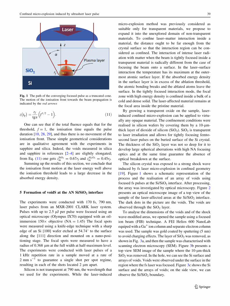
Here, we show that the motion of the ionisation front in
the direction towards the laser beam propagation, first
discovered in studies of optical breakdown in gases [14], is
a major effect determining the size of the absorption vol-
ume at the laser fluence above the ionisation threshold level
Fthr. The ionisation threshold value is reached at the
beginning of the pulse if the total energy is well above that
necessary for ionisation. The beam is focused to the focal
spot area, Sf ¼ pr2f . Laser energy increases and the ioni-
sation front, the beam cross-section where the laser fluence
is equal to the threshold value, starts to move in the
direction opposite to the pulse propagation. The spatial
shape of the beam path is a truncated cone, so assuming the
flat-top shape of the pulse the intensity at any time is
independent of the transverse coordinates (see Fig. 1).
The analysis of this simplified geometrical model can be
found in [19]. Here, we present the final result for the
distance, z(tp), to which the ionisation front moves by the
end of the pulse. This distance depends on the focusing
parameters, focal spot radius, rf, focusing angle a, and ratio
of the total fluence to the threshold value, f ¼ Flas=Fthr as
the ratio of the maximum fluence to the threshold fluence
as the following:
38 L. Rapp et al.
123
z tp� �¼ rf
tgaf 1=2 � 1� �
: ð11Þ
One can see that if the total fluence equals that for the
threshold, f = 1, the ionisation time equals the pulse
duration [10, 28, 29], and thus there is no movement of the
ionisation front. These simple geometrical considerations
are in qualitative agreement with the experiments in
sapphire and silica. Indeed, the voids measured in silica
and sapphire in references [2–4] are slightly elongated;
from Eq. (11) one gets zSiO2m = 0.67rf and zAl2O3
m = 0.45rf.
Summing up the results of this section, we conclude that
the ionisation front motion at the laser energy well above
the ionisation threshold leads to a large decrease in the
absorbed energy density.
5 Formation of voidS at the AN Si/SiO2 interface
The experiments were conducted with 170 fs, 790 nm,
laser pulses from an MXR-2001 CLARK laser system.
Pulses with up to 2.5 lJ per pulse were focused using an
optical microscope (Olympus IX70) equipped with an oil-
immersion 1509 objective (NA = 1.45) The focal spots
were measured using a knife-edge technique with a sharp
edge of an Si [100] wafer etched at 54.748 to the surface
along the [111] direction and mounted on a nano-posi-
tioning stage. The focal spots were measured to have a
radius of 0.368 lm at the full width at half-maximum level.
The experiments were conducted with laser pulses of a
1 kHz repetition rate in a sample moved at a rate of
2 mm s-1 to guarantee a single shot per spot regime,
resulting in each of the shots located 2 lm apart.
Silicon is not transparent at 790 nm, the wavelength that
we used for the experiments. While the laser-induced
micro-explosion method was previously considered as
suitable only for transparent materials, we propose to
expand it into the unexplored domain of non-transparent
materials. To confine laser–matter interaction inside a
material, the distance ought to be far enough from the
crystal surface so that the interaction region can be con-
sidered as confined. The interaction of intense laser radi-
ation with matter when the beam is tightly focused inside a
transparent material is radically different from the case of
focusing the beam onto a surface. In the laser–surface
interaction the temperature has its maximum at the outer-
most atomic surface layer. If the absorbed energy density
in the surface layer is in excess of the ablation threshold,
the atomic bonding breaks and the ablated atoms leave the
surface. In the tightly focused interaction mode, the focal
zone with high energy density is confined inside a bulk of a
cold and dense solid. The laser-affected material remains at
the focal area inside the pristine material.
By growing a transparent oxide on the sample, laser-
induced confined micro-explosion can be applied to virtu-
ally any opaque material. The confinement conditions were
realised in silicon wafers by covering them by a 10-lm-
thick layer of dioxide of silicon (SiO2). SiO2 is transparent
to laser irradiation and allows for tightly focusing femto-
second laser pulses on the buried surface of the Si crystal.
The thickness of the SiO2 layer was not so deep for it to
develop large spherical aberrations with high NA focusing
optics and at the same time guarantee the absence of
optical breakdown at the surface.
The silicon crystal was exposed to a strong shock wave
induced by fs laser micro-explosion in confined geometry
[19]. Figure 1 shows a schematic representation of the
process and the realisation of an array of voids using
focused fs pulses at the Si/SiO2 interface. After processing,
the array was investigated by optical microscopy. Figure 2
presents an optical microscope image of a top view of the
sample of the laser-affected areas at the Si/SiO2 interface.
The dark dots in the picture are the voids. The voids are
observed through the SiO2 layer.
To analyse the dimensions of the voids and of the shock
wave-modified areas, we opened the sample using a focused
ion beam (FIB) technique. A FEI Helios 600 NanoLab
equiped with a Ga? ion column and separate electron column
was used. The sample was gold coated by sputtering (5 nm)
to avoid charging effects. The layer of SiO2 was removed, as
shown in Fig. 3a, and then the sample was characterised with
scanning electron microscopy (SEM). Figure 3b presents a
top view SEM image of the sample where the 10-lm-thick
SiO2 was removed. In the hole, we can see the Si surface and
arrays of voids. Voids were observed under the surface in the
region where the fs laser was focused. Figure 3c shows the Si
surface and the arrays of voids; on the side view, we can
observe the Si/SiO2 boundary.
Fig. 1 The path of the converging focused pulse as a truncated cone.
The motion of the ionisation front towards the beam propagation is
indicated by the red arrows
Confined micro-explosion induced by ultrashort laser pulse 39
123

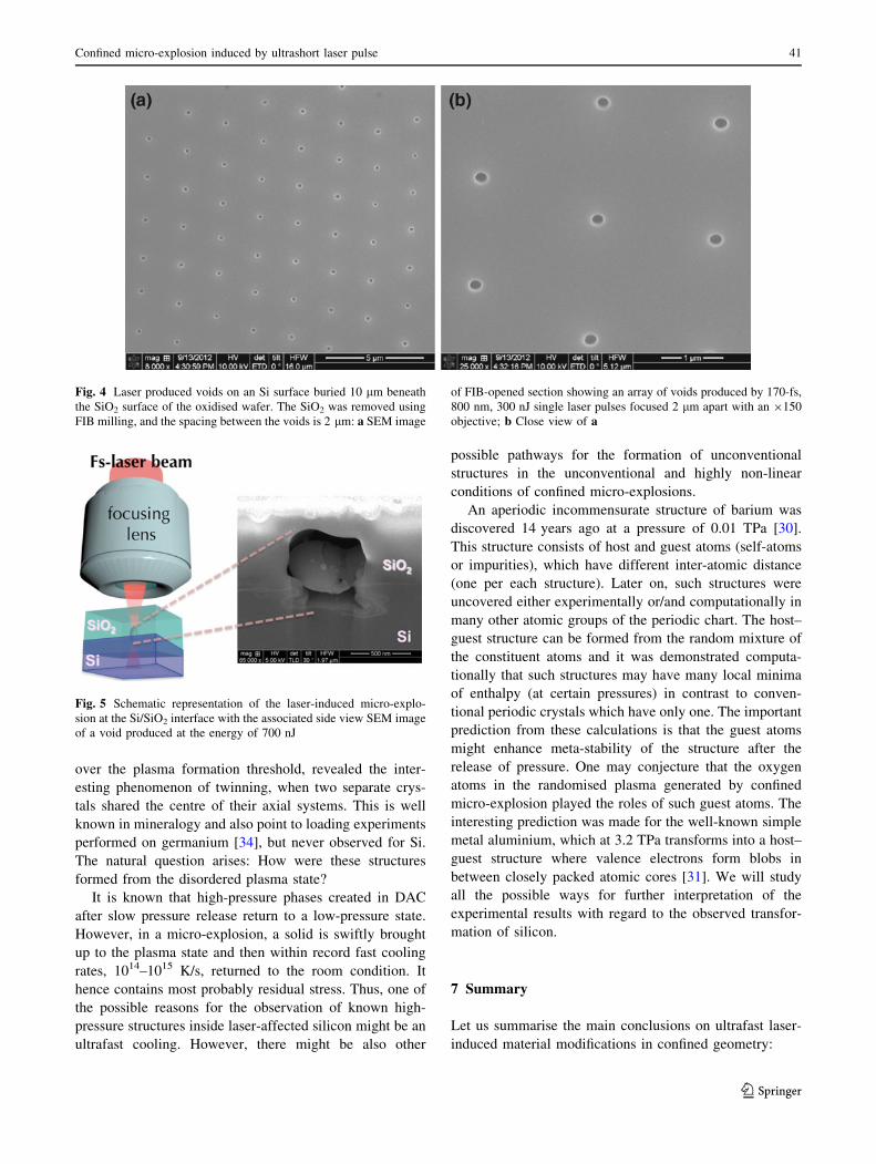
Each of the regions irradiated by a single laser pulse at
the fluence above *1 J/cm2 contains a void located at the
focal spot. Figure 4 presents arrays of voids at the Si sur-
face produced by 300 nJ single laser pulses focused 2 lm
apart with a 1509 objective. On the top view, all the voids
had a circular shape and diameter of 250 nm.
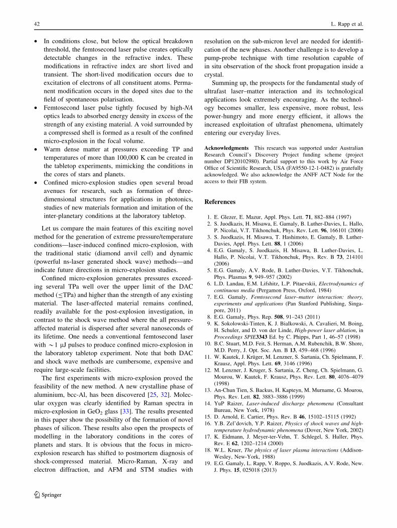
On the area where the SiO2 layer was not completely
removed, cross sections were obtained using FIB cutting
through a void and then characterised with SEM. Figure 5
shows a side view of a void produced with energy of
700 nJ. The maximal horizontal length of the void in the
SiO2 region is 720 nm and in Si 550 nm. The vertical size
(including Si and SiO2) is 1.25 lm. A shock wave-modi-
fied Si surrounded the voids.
The thickness of the boundary between the transparent
oxidised layer and crystalline Si where the laser radiation is
focused is of the order of only 2 nm and can be clearly seen
on electron microscope. Material should be removed from
the energy deposition region to form a void involving a
denser shell surrounding the void. Therefore, the observation
of a large void is unequivocal evidence of creation of pres-
sure well in excess of the Young modulus of both materials,
YSiO2* 75 GPa for SiO2 and YSi * 165 GPa for Si.
The characterisation of the laser-affected area, the dense
shell surrounding the void and the shock wave-affected
area by transmission electron microscopy and by Raman
micro-spectroscopy will be discussed elsewhere.
6 Discussion
Preliminary electron diffraction patterns of laser and
shock-affected silicon reveal the presence of known high-
pressure silicon crystals and unknown, still unidentified
structures with inter-atomic distances which cannot be
attributed to any known modifications of silicon. The
experiments with the highest laser fluence, almost 40 times
Fig. 2 Optical microscope image of arrays of void made at the Si/
SiO2 interface viewed through the SiO2 layer produced fs-pulse laser
micro-explosion. The spacing between the voids is 2 lm
Fig. 3 a Side view schematic representation of the processed sample
and of the area milled using the focused ion beam (FIB). b SEM
image of the hole made in the SiO2 layer by FIB to reach the surface
of the Si layer, following the schematic in (a). c SEM image of the
side view of the milling by FIB of the SiO2 layer to reach the surface
of the Si layer
40 L. Rapp et al.
123
over the plasma formation threshold, revealed the inter-
esting phenomenon of twinning, when two separate crys-
tals shared the centre of their axial systems. This is well
known in mineralogy and also point to loading experiments
performed on germanium [34], but never observed for Si.
The natural question arises: How were these structures
formed from the disordered plasma state?
It is known that high-pressure phases created in DAC
after slow pressure release return to a low-pressure state.
However, in a micro-explosion, a solid is swiftly brought
up to the plasma state and then within record fast cooling
rates, 1014–1015 K/s, returned to the room condition. It
hence contains most probably residual stress. Thus, one of
the possible reasons for the observation of known high-
pressure structures inside laser-affected silicon might be an
ultrafast cooling. However, there might be also other
possible pathways for the formation of unconventional
structures in the unconventional and highly non-linear
conditions of confined micro-explosions.
An aperiodic incommensurate structure of barium was
discovered 14 years ago at a pressure of 0.01 TPa [30].
This structure consists of host and guest atoms (self-atoms
or impurities), which have different inter-atomic distance
(one per each structure). Later on, such structures were
uncovered either experimentally or/and computationally in
many other atomic groups of the periodic chart. The host–
guest structure can be formed from the random mixture of
the constituent atoms and it was demonstrated computa-
tionally that such structures may have many local minima
of enthalpy (at certain pressures) in contrast to conven-
tional periodic crystals which have only one. The important
prediction from these calculations is that the guest atoms
might enhance meta-stability of the structure after the
release of pressure. One may conjecture that the oxygen
atoms in the randomised plasma generated by confined
micro-explosion played the roles of such guest atoms. The
interesting prediction was made for the well-known simple
metal aluminium, which at 3.2 TPa transforms into a host–
guest structure where valence electrons form blobs in
between closely packed atomic cores [31]. We will study
all the possible ways for further interpretation of the
experimental results with regard to the observed transfor-
mation of silicon.
7 Summary
Let us summarise the main conclusions on ultrafast laser-
induced material modifications in confined geometry:
Fig. 4 Laser produced voids on an Si surface buried 10 lm beneath
the SiO2 surface of the oxidised wafer. The SiO2 was removed using
FIB milling, and the spacing between the voids is 2 lm: a SEM image
of FIB-opened section showing an array of voids produced by 170-fs,
800 nm, 300 nJ single laser pulses focused 2 lm apart with an 9150
objective; b Close view of a
Fig. 5 Schematic representation of the laser-induced micro-explo-
sion at the Si/SiO2 interface with the associated side view SEM image
of a void produced at the energy of 700 nJ
Confined micro-explosion induced by ultrashort laser pulse 41
123
• In conditions close, but below the optical breakdown
threshold, the femtosecond laser pulse creates optically
detectable changes in the refractive index. These
modifications in refractive index are short lived and
transient. The short-lived modification occurs due to
excitation of electrons of all constituent atoms. Perma-
nent modification occurs in the doped sites due to the
field of spontaneous polarisation.
• Femtosecond laser pulse tightly focused by high-NA
optics leads to absorbed energy density in excess of the
strength of any existing material. A void surrounded by
a compressed shell is formed as a result of the confined
micro-explosion in the focal volume.
• Warm dense matter at pressures exceeding TP and
temperatures of more than 100,000 K can be created in
the tabletop experiments, mimicking the conditions in
the cores of stars and planets.
• Confined micro-explosion studies open several broad
avenues for research, such as formation of three-
dimensional structures for applications in photonics,
studies of new materials formation and imitation of the
inter-planetary conditions at the laboratory tabletop.
Let us compare the main features of this exciting novel
method for the generation of extreme pressure/temperature
conditions—laser-induced confined micro-explosion, with
the traditional static (diamond anvil cell) and dynamic
(powerful ns-laser generated shock wave) methods—and
indicate future directions in micro-explosion studies.
Confined micro-explosion generates pressures exceed-
ing several TPa well over the upper limit of the DAC
method (BTPa) and higher than the strength of any existing
material. The laser-affected material remains confined,
readily available for the post-explosion investigation, in
contrast to the shock wave method where the all pressure-
affected material is dispersed after several nanoseconds of
its lifetime. One needs a conventional femtosecond laser
with *1 lJ pulses to produce confined micro-explosion in
the laboratory tabletop experiment. Note that both DAC
and shock wave methods are cumbersome, expensive and
require large-scale facilities.
The first experiments with micro-explosion proved the
feasibility of the new method. A new crystalline phase of
aluminium, bcc-Al, has been discovered [25, 32]. Molec-
ular oxygen was clearly identified by Raman spectra in
micro-explosion in GeO2 glass [33]. The results presented
in this paper show the possibility of the formation of novel
phases of silicon. These results also open the prospects of
modelling in the laboratory conditions in the cores of
planets and stars. It is obvious that the focus in micro-
explosion research has shifted to postmortem diagnosis of
shock-compressed material. Micro-Raman, X-ray and
electron diffraction, and AFM and STM studies with
resolution on the sub-micron level are needed for identifi-
cation of the new phases. Another challenge is to develop a
pump-probe technique with time resolution capable of
in situ observation of the shock front propagation inside a
crystal.
Summing up, the prospects for the fundamental study of
ultrafast laser–matter interaction and its technological
applications look extremely encouraging. As the technol-
ogy becomes smaller, less expensive, more robust, less
power-hungry and more energy efficient, it allows the
increased exploitation of ultrafast phenomena, ultimately
entering our everyday lives.
Acknowledgments This research was supported under Australian
Research Council’s Discovery Project funding scheme (project
number DP120102980). Partial support to this work by Air Force
Office of Scientific Research, USA (FA9550-12-1-0482) is gratefully
acknowledged. We also acknowledge the ANFF ACT Node for the
access to their FIB system.
References
1. E. Glezer, E. Mazur, Appl. Phys. Lett. 71, 882–884 (1997)
2. S. Juodkazis, H. Misawa, E. Gamaly, B. Luther-Davies, L. Hallo,
P. Nicolai, V.T. Tikhonchuk, Phys. Rev. Lett. 96, 166101 (2006)
3. S. Juodkazis, H. Misawa, T. Hashimoto, E. Gamaly, B. Luther-
Davies, Appl. Phys. Lett. 88, 1 (2006)
4. E.G. Gamaly, S. Juodkazis, H. Misawa, B. Luther-Davies, L.
Hallo, P. Nicolai, V.T. Tikhonchuk, Phys. Rev. B 73, 214101
(2006)
5. E.G. Gamaly, A.V. Rode, B. Luther-Davies, V.T. Tikhonchuk,
Phys. Plasmas 9, 949–957 (2002)
6. L.D. Landau, E.M. Lifshitz, L.P. Pitaevskii, Electrodynamics of
continuous media (Pergamon Press, Oxford, 1984)
7. E.G. Gamaly, Femtosecond laser–matter interaction: theory,
experiments and applications (Pan Stanford Publishing, Singa-
pore, 2011)
8. E.G. Gamaly, Phys. Rep. 508, 91–243 (2011)
9. K. Sokolowski-Tinten, K. J. Bialkowski, A. Cavalieri, M. Boing,
H. Schuler, and D. von der Linde, High-power laser ablation, in
Proceedings SPIE3343 Ed. by C. Phipps, Part 1, 46–57 (1998)
10. B.C. Stuart, M.D. Feit, S. Herman, A.M. Rubenchik, B.W. Shore,
M.D. Perry, J. Opt. Soc. Am. B 13, 459–468 (1996)
11. W. Kautek, J. Kruger, M. Lenzner, S. Sartania, Ch. Spielmann, F.
Krausz, Appl. Phys. Lett. 69, 3146 (1996)
12. M. Lenzner, J. Kruger, S. Sartania, Z. Cheng, Ch. Spielmann, G.
Mourou, W. Kautek, F. Krausz, Phys. Rev. Lett. 80, 4076–4079
(1998)
13. An-Chun Tien, S. Backus, H. Kapteyn, M. Murname, G. Mourou,
Phys. Rev. Lett. 82, 3883–3886 (1999)
14. YuP Raizer, Laser-induced discharge phenomena (Consultant
Bureau, New York, 1978)
15. D. Arnold, E. Cartier, Phys. Rev. B 46, 15102–15115 (1992)
16. Y.B. Zel’dovich, Y.P. Raizer, Physics of shock waves and high-
temperature hydrodynamic phenomena (Dover, New York, 2002)
17. K. Eidmann, J. Meyer-ter-Vehn, T. Schlegel, S. Huller, Phys.
Rev. E 62, 1202–1214 (2000)
18. W.L. Kruer, The physics of laser plasma interactions (Addison-
Wesley, New-York, 1988)
19. E.G. Gamaly, L. Rapp, V. Roppo, S. Juodkazis, A.V. Rode, New.
J. Phys. 15, 025018 (2013)
42 L. Rapp et al.
123
20. Sheng-Nian Luo, T.J. Arens, P.D. Asimov, J. Geophys. Res. 108,
2421 (2003)
21. S. Brygoo, E. Henry, P. Loubeyre, J. Eggert, M. Koenig, B.
Loupias, A. Benuzzi-Mounaix, M.R. Le Gloahec, Nat. Mater. 6,
274–277 (2007)
22. D.G. Hicks, P.M. Celliers, G.W. Collins, J.H. Eggert, S.J. Moon,
Phys. Rev. Lett. 91, 035502 (2003)
23. D.C. Swift, J.A. Hawreliak, D. Braun, A. Kritcher, S. Glenzer, G.
Collins, S. D. Rothman, D. Chapman and S. Rose, Gigabar
material properties experiments on NIF and Omega. in Shock
Compression of Condense Matter – 2011, AIP Conf. Proc. 1426,
477–480 (2012)
24. R.F. Trunin, Phys. Uspekhi 37, 1123–1146 (1994)
25. A. Vailionis, E.G. Gamaly, V. Mizeikis, W. Yang, A.V. Rode, S.
Juodkazis, Nat. Commun. 2, 445 (2011)
26. E.N. Glezer, M. Milosavjevic, L. Huang, R.J. Finlay, T.-H. Her,
J.P. Callan, E. Masur, Opt. Lett. 21, 2023–2026 (1996)
27. S.A. Akhmanov, V.A. Vyspoukh, A.S. Chirkin, Optics of fem-
tosecond laser pulses (Nauka, Moscow, 1988)
28. V.V. Temnov, K. Sokolowski-Tinten, P. Zhou, A. El-Khamhawy,
D. von der Linde, Phys. Rev. Lett. 97, 237403 (2006)
29. B.C. Stuart, M.D. Feit, A.M. Rubenchick, B.W. Shore, M.D.
Perry, Phys. Rev. Lett. 74, 2248–2251 (1995)
30. R.J. Nelmes, D.R. Allan, M.I. McMahon, S.A. Belmonte, Phys.
Rev. Lett. 83, 4081 (1999)
31. C.J. Pickard, R.J. Needs, Nat. Mater. 9, 624–627 (2010)
32. E.G. Gamaly, A. Vailionis, V. Mizeikis, W. Yang, A.V. Rode, S.
Juodkazis, High Energy Density Phys. 8, 13–17 (2012)
33. L. Bressel, D. de Ligny, E.G. Gamaly, A.V. Rode, S. Juodkazis,
Opt. Mat. Express 1, 1150–1157 (2011)
34. S.J. Lloyd, A. Castellero, F. Giuliani, Y. Long, K.K. McLaughlin,
J.M. Molina-Aldareguia, Proc. R. Soc. A 461, 2521–2543 (2005)
Confined micro-explosion induced by ultrashort laser pulse 43
123