Compensation of droop control using common load condition in DC microgrids to improve voltage...
9
Compensation of droop control using common load condition in DC microgrids to improve voltage regulation and load sharing Nanfang Yang a,⇑ , Damien Paire a , Fei Gao a , Abdellatif Miraoui a , Weiguo Liu b a IRTES-SET, University of Technology of Belfort-Montbéliard, 90010 Belfort Cedex, France b Department of Electrical Engineering, Northwestern Polytechnical University, 710072 Xi’an, PR China article info Article history: Received 24 March 2014 Received in revised form 10 July 2014 Accepted 25 July 2014 Available online 24 August 2014 Keywords: DC microgrid Distributed power generation Droop control abstract DC microgrid is one feasible and effective solution to integrate renewable energy resources, as well as to supply reliable electricity. The control objective of DC microgrids is to obtain system stability, low voltage regulation and equal load sharing in per unit. The droop control is an effectively method adopted to implement the control of microgrids with multiple distributed energy units. However in the application of low-voltage DC microgrids, the nominal reference mismatch and unequal cable resistances require a trade-off to be made between voltage regulation and load sharing. In this paper, a unified compensation framework is proposed using the common load condition in local controller, to compensate the voltage drop and load sharing errors. The voltage deviation is compensated with a P controller while the load sharing is compensated through a PI controller. An additional low bandwidth communication is introduced to share the output current information, and the average output current in per unit is generated to represent the common load condition. The performance of the proposed method is analyzed and compared with basic droop control and hierarchical structure method. The large signal stability is analyzed to define the margin of compensation coefficients. Simulations and experiments are carried out to verify the performance of the proposed method. Ó 2014 Elsevier Ltd. All rights reserved. Introduction Nowadays, microgrids are gaining more and more interest, due to their ability to integrate local distributed energy sources, energy storages, and controllable loads, as well as the improvement of electricity supply stability, efficiency and reduction of environ- mental impact. Power electronics converters are usually adopted to connect the distributed energy units with the microgrid. The microgrid is viewed as the system of multiple paralleling power converter interfaced distributed energy units (DEUs), and the oper- ation of microgrid depends on the control of DEUs. Although most of existing microgrids are in AC form, DC microgrids have been investigated in several applications such as, data centers [1,2], marine power systems [3–5], and residential applications [6]. The efficiency analyses show that the losses of DC microgrids is around 15% lower than that of AC microgrids during one year due to the elimination of energy conversions from DC to AC and AC to DC [7]. Besides, the adoption of DC microgrids can also avoid the con- sideration of reactive power and frequency synchronization. The major control objective of low-voltage DC microgrids is to obtain low voltage regulation, as well as equal load sharing in per unit among DEUs [8,9]. The control methods in literature are mainly divided into two major categories: Master/Slave control [10] and droop control [11,12]. Although the Master/Slave control can achieve good voltage regulation and load sharing, the main drawback is that the entire system operation is highly dependent on the master unit and high bandwidth communication [13]. The failure of the master unit will cause the outage of the entire system immediately. While in the case of droop control, two or more units participate in the voltage regulation, therefore disconnection or reconnection of one unit has slight impact to the system operation, the power balance is achieved automatically with redistribution of the load among DEUs. Droop control is an output impedance programming method without requirement of communication, the output voltage line- arly decreases with the output current/power. In AC microgrids, the real power–frequency (P=f ) droop and reactive power–voltage (Q =V ) droop laws are deduced under the condition that the trans- mission lines are mainly inductive [14]. The control of active power and reactive power becomes coupling, when both the resistance http://dx.doi.org/10.1016/j.ijepes.2014.07.079 0142-0615/Ó 2014 Elsevier Ltd. All rights reserved. ⇑ Corresponding author. E-mail addresses: [email protected] (N. Yang), [email protected] (D. Paire), [email protected] (F. Gao), [email protected] (A. Miraoui), [email protected] (W. Liu). URL: http://www.energyconversion.fr (N. Yang). Electrical Power and Energy Systems 64 (2015) 752–760 Contents lists available at ScienceDirect Electrical Power and Energy Systems journal homepage: www.elsevier.com/locate/ijepes
Transcript of Compensation of droop control using common load condition in DC microgrids to improve voltage...
Electrical Power and Energy Systems 64 (2015) 752–760
Contents lists available at ScienceDirect
Electrical Power and Energy Systems
journal homepage: www.elsevier .com/locate / i jepes
Compensation of droop control using common load condition in DCmicrogrids to improve voltage regulation and load sharing
http://dx.doi.org/10.1016/j.ijepes.2014.07.0790142-0615/� 2014 Elsevier Ltd. All rights reserved.
⇑ Corresponding author.E-mail addresses: [email protected] (N. Yang), [email protected]
(D. Paire), [email protected] (F. Gao), [email protected] (A. Miraoui),[email protected] (W. Liu).
URL: http://www.energyconversion.fr (N. Yang).
Nanfang Yang a,⇑, Damien Paire a, Fei Gao a, Abdellatif Miraoui a, Weiguo Liu b
a IRTES-SET, University of Technology of Belfort-Montbéliard, 90010 Belfort Cedex, Franceb Department of Electrical Engineering, Northwestern Polytechnical University, 710072 Xi’an, PR China
a r t i c l e i n f o a b s t r a c t
Article history:Received 24 March 2014Received in revised form 10 July 2014Accepted 25 July 2014Available online 24 August 2014
Keywords:DC microgridDistributed power generationDroop control
DC microgrid is one feasible and effective solution to integrate renewable energy resources, as well as tosupply reliable electricity. The control objective of DC microgrids is to obtain system stability, low voltageregulation and equal load sharing in per unit. The droop control is an effectively method adopted toimplement the control of microgrids with multiple distributed energy units. However in the applicationof low-voltage DC microgrids, the nominal reference mismatch and unequal cable resistances require atrade-off to be made between voltage regulation and load sharing. In this paper, a unified compensationframework is proposed using the common load condition in local controller, to compensate the voltagedrop and load sharing errors. The voltage deviation is compensated with a P controller while the loadsharing is compensated through a PI controller. An additional low bandwidth communication isintroduced to share the output current information, and the average output current in per unit isgenerated to represent the common load condition. The performance of the proposed method is analyzedand compared with basic droop control and hierarchical structure method. The large signal stability isanalyzed to define the margin of compensation coefficients. Simulations and experiments are carriedout to verify the performance of the proposed method.
� 2014 Elsevier Ltd. All rights reserved.
Introduction
Nowadays, microgrids are gaining more and more interest, dueto their ability to integrate local distributed energy sources, energystorages, and controllable loads, as well as the improvement ofelectricity supply stability, efficiency and reduction of environ-mental impact. Power electronics converters are usually adoptedto connect the distributed energy units with the microgrid. Themicrogrid is viewed as the system of multiple paralleling powerconverter interfaced distributed energy units (DEUs), and the oper-ation of microgrid depends on the control of DEUs. Although mostof existing microgrids are in AC form, DC microgrids have beeninvestigated in several applications such as, data centers [1,2],marine power systems [3–5], and residential applications [6]. Theefficiency analyses show that the losses of DC microgrids is around15% lower than that of AC microgrids during one year due to theelimination of energy conversions from DC to AC and AC to DC
[7]. Besides, the adoption of DC microgrids can also avoid the con-sideration of reactive power and frequency synchronization.
The major control objective of low-voltage DC microgrids is toobtain low voltage regulation, as well as equal load sharing inper unit among DEUs [8,9]. The control methods in literature aremainly divided into two major categories: Master/Slave control[10] and droop control [11,12]. Although the Master/Slave controlcan achieve good voltage regulation and load sharing, the maindrawback is that the entire system operation is highly dependenton the master unit and high bandwidth communication [13]. Thefailure of the master unit will cause the outage of the entire systemimmediately. While in the case of droop control, two or more unitsparticipate in the voltage regulation, therefore disconnection orreconnection of one unit has slight impact to the system operation,the power balance is achieved automatically with redistribution ofthe load among DEUs.
Droop control is an output impedance programming methodwithout requirement of communication, the output voltage line-arly decreases with the output current/power. In AC microgrids,the real power–frequency (P=f ) droop and reactive power–voltage(Q=V) droop laws are deduced under the condition that the trans-mission lines are mainly inductive [14]. The control of active powerand reactive power becomes coupling, when both the resistance
N. Yang et al. / Electrical Power and Energy Systems 64 (2015) 752–760 753
and inductance of the transmission line are considered in low-volt-age AC applications. An orthogonal linear rotational transformationmethod [15] is adopted to decouple the power control. The activepower P and reactive power Q are transformed to ‘‘modified’’ activepower P0 and reactive power Q 0 to apply droop control laws,another similar method is also referred as virtual frequency–voltage frame [16]. The frequency is a global variable through theentire system, but not the voltage magnitude, the voltage dropsin transmission lines will lead to unequal sharing of reactivepower. The virtual resistance [17] or virtual impedance [18,19]methods are proposed to match the line impedances. Thecompensation method using a modified voltage _V is introducedin [20], in which the time rate change of the converter outputvoltage magnitude _V is used to control the reactive power Qcontrol with modified voltage _V .
In DC microgrids, the power–voltage P=V droop control [21] canbe implemented using DC bus signaling [22,23], in which the lineresistances and voltage sensing errors are not considered, andthe DC voltage is controlled in a relatively large range. Howeverin the low-voltage DC applications, the line resistances cannot beomitted, and the similar problem is faced as the reactive powercontrol in low-voltage AC grids. The challenges are the voltagedeviation caused by the droop control, the load sharing error or cir-culated current [24] introduced by the unequal line parametersand nominal voltage reference offsets. The choice of droop con-stants needs to consider the balance of voltage accuracy and loadsharing performance [25]. When higher droop constants are cho-sen, better load sharing can be obtained, however this also leadsto larger microgrid voltage drops. The impact of the line voltagedrops on the load sharing, depends on the topology of the DCmicrogrid, the location of the load changes, the transmission lineparameters and voltage droop constants [8,13,26]. This makesthe compensation methods according full knowledge of the systemnot suitable. Not only the uncertain transmission lines cause theunequal load sharing but also the nominal voltage referenceoffsets. The voltage control loop of the power converter dependson the feedback sensing signal of the output voltage, and theunavoidable errors in the voltage signals also lead to load sharingperformance deterioration [24].
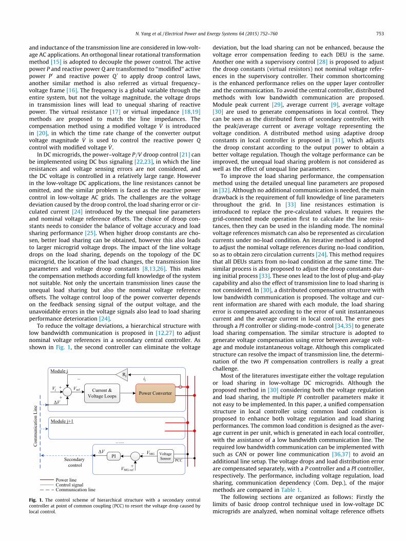
To reduce the voltage deviations, a hierarchical structure withlow bandwidth communication is proposed in [12,27] to adjustnominal voltage references in a secondary central controller. Asshown in Fig. 1, the second controller can eliminate the voltage
Fig. 1. The control scheme of hierarchical structure with a secondary centralcontroller at point of common coupling (PCC) to resort the voltage drop caused bylocal control.
deviation, but the load sharing can not be enhanced, because thevoltage error compensation feeding to each DEU is the same.Another one with a supervisory control [28] is proposed to adjustthe droop constants (virtual resistors) not nominal voltage refer-ences in the supervisory controller. Their common shortcomingis the enhanced performance relies on the upper layer controllerand the communication. To avoid the central controller, distributedmethods with low bandwidth communication are proposed.Module peak current [29], average current [9], average voltage[30] are used to generate compensations in local control. Theycan be seen as the distributed form of secondary controller, withthe peak/average current or average voltage representing thevoltage condition. A distributed method using adaptive droopconstants in local controller is proposed in [31], which adjuststhe droop constant according to the output power to obtain abetter voltage regulation. Though the voltage performance can beimproved, the unequal load sharing problem is not considered aswell as the effect of unequal line parameters.
To improve the load sharing performance, the compensationmethod using the detailed unequal line parameters are proposedin [32]. Although no additional communication is needed, the maindrawback is the requirement of full knowledge of line parametersthroughout the grid. In [33] line resistances estimation isintroduced to replace the pre-calculated values. It requires thegrid-connected mode operation first to calculate the line resis-tances, then they can be used in the islanding mode. The nominalvoltage references mismatch can also be represented as circulationcurrents under no-load condition. An iterative method is adoptedto adjust the nominal voltage references during no-load condition,so as to obtain zero circulation currents [24]. This method requiresthat all DEUs starts from no-load condition at the same time. Thesimilar process is also proposed to adjust the droop constants dur-ing initial process [33]. These ones lead to the lost of plug-and-playcapability and also the effect of transmission line to load sharing isnot considered. In [30], a distributed compensation structure withlow bandwidth communication is proposed. The voltage and cur-rent information are shared with each module, the load sharingerror is compensated according to the error of unit instantaneouscurrent and the average current in local control. The error goesthrough a PI controller or sliding-mode-control [34,35] to generateload sharing compensation. The similar structure is adopted togenerate voltage compensation using error between average volt-age and module instantaneous voltage. Although this complicatedstructure can resolve the impact of transmission line, the determi-nation of the two PI compensation controllers is really a greatchallenge.
Most of the literatures investigate either the voltage regulationor load sharing in low-voltage DC microgrids. Although theproposed method in [30] considering both the voltage regulationand load sharing, the multiple PI controller parameters make itnot easy to be implemented. In this paper, a unified compensationstructure in local controller using common load condition isproposed to enhance both voltage regulation and load sharingperformances. The common load condition is designed as the aver-age current in per unit, which is generated in each local controller,with the assistance of a low bandwidth communication line. Therequired low bandwidth communication can be implemented withsuch as CAN or power line communication [36,37] to avoid anadditional line setup. The voltage drops and load distribution errorare compensated separately, with a P controller and a PI controller,respectively. The performance, including voltage regulation, loadsharing, communication dependency (Com. Dep.), of the majormethods are compared in Table 1.
The following sections are organized as follows: Firstly thelimits of basic droop control technique used in low-voltage DCmicrogrids are analyzed, when nominal voltage reference offsets
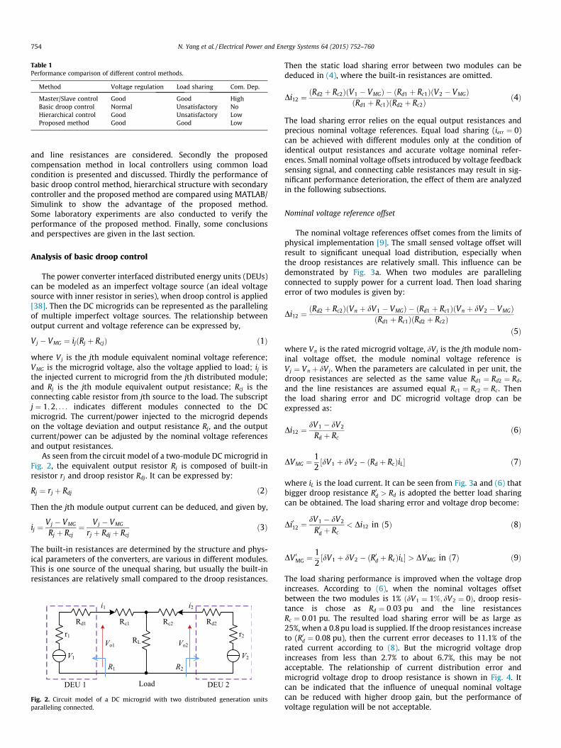
Table 1Performance comparison of different control methods.
Method Voltage regulation Load sharing Com. Dep.
Master/Slave control Good Good HighBasic droop control Normal Unsatisfactory NoHierarchical control Good Unsatisfactory LowProposed method Good Good Low
754 N. Yang et al. / Electrical Power and Energy Systems 64 (2015) 752–760
and line resistances are considered. Secondly the proposedcompensation method in local controllers using common loadcondition is presented and discussed. Thirdly the performance ofbasic droop control method, hierarchical structure with secondarycontroller and the proposed method are compared using MATLAB/Simulink to show the advantage of the proposed method.Some laboratory experiments are also conducted to verify theperformance of the proposed method. Finally, some conclusionsand perspectives are given in the last section.
Analysis of basic droop control
The power converter interfaced distributed energy units (DEUs)can be modeled as an imperfect voltage source (an ideal voltagesource with inner resistor in series), when droop control is applied[38]. Then the DC microgrids can be represented as the parallelingof multiple imperfect voltage sources. The relationship betweenoutput current and voltage reference can be expressed by,
Vj � VMG ¼ ijðRj þ RcjÞ ð1Þ
where Vj is the jth module equivalent nominal voltage reference;VMG is the microgrid voltage, also the voltage applied to load; ij isthe injected current to microgrid from the jth distributed module;and Rj is the jth module equivalent output resistance; Rcj is theconnecting cable resistor from jth source to the load. The subscriptj ¼ 1;2; . . . indicates different modules connected to the DCmicrogrid. The current/power injected to the microgrid dependson the voltage deviation and output resistance Rj, and the outputcurrent/power can be adjusted by the nominal voltage referencesand output resistances.
As seen from the circuit model of a two-module DC microgrid inFig. 2, the equivalent output resistor Rj is composed of built-inresistor rj and droop resistor Rdj. It can be expressed by:
Rj ¼ rj þ Rdj ð2Þ
Then the jth module output current can be deduced, and given by,
ij ¼Vj � VMG
Rj þ Rcj¼ Vj � VMG
rj þ Rdj þ Rcjð3Þ
The built-in resistances are determined by the structure and phys-ical parameters of the converters, are various in different modules.This is one source of the unequal sharing, but usually the built-inresistances are relatively small compared to the droop resistances.
Fig. 2. Circuit model of a DC microgrid with two distributed generation unitsparalleling connected.
Then the static load sharing error between two modules can bededuced in (4), where the built-in resistances are omitted.
Di12 ¼ðRd2 þ Rc2ÞðV1 � VMGÞ � ðRd1 þ Rc1ÞðV2 � VMGÞ
ðRd1 þ Rc1ÞðRd2 þ Rc2Þð4Þ
The load sharing error relies on the equal output resistances andprecious nominal voltage references. Equal load sharing (ierr ¼ 0)can be achieved with different modules only at the condition ofidentical output resistances and accurate voltage nominal refer-ences. Small nominal voltage offsets introduced by voltage feedbacksensing signal, and connecting cable resistances may result in sig-nificant performance deterioration, the effect of them are analyzedin the following subsections.
Nominal voltage reference offset
The nominal voltage references offset comes from the limits ofphysical implementation [9]. The small sensed voltage offset willresult to significant unequal load distribution, especially whenthe droop resistances are relatively small. This influence can bedemonstrated by Fig. 3a. When two modules are parallelingconnected to supply power for a current load. Then load sharingerror of two modules is given by:
Di12 ¼ðRd2 þ Rc2ÞðVn þ dV1 � VMGÞ � ðRd1 þ Rc1ÞðVn þ dV2 � VMGÞ
ðRd1 þ Rc1ÞðRd2 þ Rc2Þð5Þ
where Vn is the rated microgrid voltage, dVj is the jth module nom-inal voltage offset, the module nominal voltage reference isVj ¼ Vn þ dVj. When the parameters are calculated in per unit, thedroop resistances are selected as the same value Rd1 ¼ Rd2 ¼ Rd,and the line resistances are assumed equal Rc1 ¼ Rc2 ¼ Rc . Thenthe load sharing error and DC microgrid voltage drop can beexpressed as:
Di12 ¼dV1 � dV2
Rd þ Rcð6Þ
DVMG ¼12½dV1 þ dV2 � ðRd þ RcÞiL� ð7Þ
where iL is the load current. It can be seen from Fig. 3a and (6) thatbigger droop resistance R0d > Rd is adopted the better load sharingcan be obtained. The load sharing error and voltage drop become:
Di012 ¼dV1 � dV2
R0d þ Rc< Di12 in ð5Þ ð8Þ
DV 0MG ¼12½dV1 þ dV2 � ðR0d þ RcÞiL� > DVMG in ð7Þ ð9Þ
The load sharing performance is improved when the voltage dropincreases. According to (6), when the nominal voltages offsetbetween the two modules is 1% ðdV1 ¼ 1%; dV2 ¼ 0Þ, droop resis-tance is chose as Rd ¼ 0:03 pu and the line resistancesRc ¼ 0:01 pu. The resulted load sharing error will be as large as25%, when a 0.8pu load is supplied. If the droop resistances increaseto (R0d ¼ 0:08 pu), then the current error deceases to 11.1% of therated current according to (8). But the microgrid voltage dropincreases from less than 2.7% to about 6.7%, this may be notacceptable. The relationship of current distribution error andmicrogrid voltage drop to droop resistance is shown in Fig. 4. Itcan be indicated that the influence of unequal nominal voltagecan be reduced with higher droop gain, but the performance ofvoltage regulation will be not acceptable.

Voltage
VMG Rd1+Rc1
Currenti2 i’1 i1
V1V2
V’MG
i’2
Rd2+Rc2
R’d1+Rc1R’d2+Rc2Δi12
Δi’12
Voltage
VMG
Currenti2 i’1 i1i’2
V1,V2
V’MG
Rd1+Rc1Rd2+Rc2
R’d1+Rc1R’d2+Rc2
Δi12
Δi’12
Fig. 3. The output characteristics of two paralleled distributed generation units with resistive load, the influences of nominal voltage references mismatches and unequalcable resistances are considered while built-in resistances are omitted. Different droop resistances R0d1 ¼ R0d2 and Rd1 ¼ Rd2 are adopted to analyze the voltage and load sharingperformance. (a) The nominal voltage references are different, the line resistances are equal Rc1 ¼ Rc2; (b) The nominal voltage references are assumed to be equal and the lineresistances are different Rc1 < Rc2.
Fig. 4. The relationships of load sharing error to droop resistance and the voltage drop to droop resistance, with 1% nominal voltage reference offset between two modules isconsidered.
N. Yang et al. / Electrical Power and Energy Systems 64 (2015) 752–760 755
Unequal cable resistances
When the unequal line resistances, due to various geographiclocations are comparable to droop resistances, this will incur sig-nificant unequal load sharing. It can be demonstrated in Fig. 3b.Similarly, the effect of unequal line resistances can be reduced byrelative higher droop resistances, but the low voltage regulationcannot be satisfied. If the nominal voltage reference error is notconsidered (V1 ¼ V2 ¼ Vn), the load sharing error can be deducedfrom (10).
Di12 ¼ðRd2 þ Rc2ÞðVn � VMGÞ � ðRd1 þ Rc1ÞðVn � VMGÞ
ðRd1 þ Rc1ÞðRd2 þ Rc2Þð10Þ
where Vn is the rated microgrid voltage. When the parameters arecalculated in per unit, the droop resistances are selected as thesame value Rd1 ¼ Rd2 ¼ Rd. Then the load sharing error and DCmicrogrid voltage drop can be expressed as:
Di12 ¼Rc2 � Rc1
ðRd þ Rc1ÞðRd þ Rc2Þð11Þ
DVMG ¼ Vn �Rd þ Rc1
2Rd þ Rc1 þ Rc2iL ð12Þ
If bigger droop resistors (R0d > Rd) are adopted, the load sharingerror and voltage drop can be expressed as:
Di012 ¼Rc2 � Rc1
ðR0d þ Rc1ÞðR0d þ Rc2Þ< Di12 in ð11Þ ð13Þ
DV 0MG ¼ Vn �R0d þ Rc1
2R0d þ Rc1 þ Rc2iL > DVMG in ð12Þ ð14Þ
Then a better load sharing is achieved, but with bigger voltage dropat the same time.
In brief, basic droop control benefits high reliability and easyimplementation because it does not require any communication
between connected modules. On the other hand, this schememakes it actually an open loop technique to individually programthe output impedance of each module. Thus a trade-off must bemade between the load sharing and output voltage regulation. Alow bandwidth communication may be a good choice, to adjustdroop resistance or nominal voltage reference, so as to achievebetter voltage regulation and load sharing simultaneously.
Proposed compensation method
The limits of basic droop control are the conflict betweenvoltage regulation and load distribution, the sensitivities tonominal voltage reference errors and unequal connecting cableresistances. Though the adoption of higher droop gains, couldenhance the load distribution performance, it makes the voltagedrops cannot be tolerable, and also high droop gains may causethe stability problem. Therefore, the voltage drop and unequal loaddistribution need to be compensated though specified designedstructures. The DC voltage drops are derived from the droop con-trol using in local controllers, while the unequal current/powersharing results from unequal output impedance among parallelingconnected modules. Therefore, the voltage regulation and loadsharing can be compensated separately by corresponding methods,according to their different sources.
The proposed control structure is shown in Fig. 5, an additionalcommunication line such as CAN bus is introduced to exchange theload sharing condition. In the local controller, the output current ofall the units are received to generate the common load conditioniavg in per unit given by:
iavg ¼Pn
1ijInjPn1Inj
ð15Þ
where Inj and in are the jth module rated current and instantaneousoutput current. The design of the voltage and current sharingcompensations are discussed in the following subsections.

Fig. 5. The control scheme of the proposed compensation method.
Fig. 6. The general model of one energy unit supply constant power load.
756 N. Yang et al. / Electrical Power and Energy Systems 64 (2015) 752–760
Voltage deviation compensation
When droop control applied, the output voltage drops linearlyto the output current/power, and then the output currents can beused to compensate the voltage drops. The voltage across the DCtransmission line is not constant, can not be used as the global var-iable like frequency in AC microgrid. While the common load con-dition can be presented by the average current/power value in perunit, it changes with the condition of load, like the function of fre-quency in AC microgrid. Then it can be used to produce voltagecompensation, by multiplying a voltage compensation coefficient.The voltage compensations can uplift the microgrid voltage level,by adding same voltage error to each module. The compensationcan be expressed by,
DV 0j ¼ Kjiavg ð16Þ
where the Kj is the compensation coefficient to restore microgridvoltage, and it should be selected the same value in per unit for dif-ferent modules, but smaller than the droop resistance to retain thedroop control function [9] and also maintain the system stability(some detailed analyses are shown in ‘Large signal stability analy-sis’). When only one module supplies power to the load, the voltageerror Vdrop can be given by (17), if nominal voltage reference offset isnot considered.
Vdrop ¼ Rjij � Kjij ð17Þ
The common load condition iavg equals to the module current ij, andthe microgrid voltage level can be restored. If the compensationcoefficient is selected half of the droop resistance, the voltage errorwould decrease to half. The merit is that: the voltage compensa-tions are distributed in local controllers, without the dependencyof a central controller referred in [12].
Load sharing compensation
The compensation of unequal load distribution is designed in adifferent way, with the help of low bandwidth communication. Thecommon load condition iavg is used to compare with moduleinstantaneous current, and then the error feeds a PI to generateload sharing compensation in each local controller. The load shar-ing compensation can be expressed by,
DV 00j ¼KPjsþ KIj
sðiavg � ijÞ ð18Þ
where s is the integrator; KPj and KIj are the parameters of loadsharing compensator in the jth module local controller. The loadsharing compensation various with different modules. In steady
state, the output current in per unit of each module is controlledto follow the common reference, thus ideally there is no load shar-ing error. The adoption of per unit system with modules of differentcapacities, reduces the communication burden and calculationcomplexity of the common load reference generation.
Large signal stability analysis
The proposed compensation method will reduce the effect ofdroop control, and affect the stability of the local controller with-out choosing a proper compensation gains, especially when theconstant power load (CPL) is connected [39]. In this part, the volt-age and current compensation are viewed as an adaptive outputresistance, and the stability analysis is conducted to find out themargin of output resistance. The droop control loop and compensa-tion loops are relatively slow compared with the voltage controlloop, thus in this analysis the effect of droop loop and compensa-tion are analyzed together.
The scheme of one energy unit supplying power for a CPL isshown in Fig. 6, in which the equivalent output resistance Rs isfunction of output current, common current reference, it is usedto represent the effect of droop resistor, voltage and currentsharing compensations:
Rs ¼ f ðis; iavgÞ ð19Þ
Then the large signal stability analysis model can be given by:
_x1
_x2
� �¼� Rs
Ls� 1
Ls
1Cs
PsCsVs0
x2x2þVs0
" #x1
x2
� �ð20Þ
where the state variables are defined as:
x1 ¼ is � Is0
x2 ¼ Vs � Vs0
�ð21Þ
and Ps is the constant power load supplied by the energy unit. Theparameters using for this analysis are given as follow:
Nominal voltage : Ve ¼ 100 VRated current : In ¼ 10 AEquivalent resistance : Rs ¼ 0:5 X ðadjustableÞEquivalent inductance : Ls ¼ 10 mHOutput capacitance : Cs ¼ 1:0 mFConstant load : Ps ¼ 750 W
8>>>>>>>><>>>>>>>>:
ð22Þ
The equivalent resistance is chosen as the droop resistance 0:3 X(0.03 pu with the base resistance Rb ¼ 10 X), the initial state voltageVs0 can be calculated by:
Vs0 ¼Ve �
ffiffiffiffiffiffiffiffiffiffiffiffiffiffiffiffiffiffiffiffiffiffiffiV2
e � 4PsRs
q2
ð23Þ
The stability is analysis using the multi-model approach [40],and the domains of attraction with different equivalent outputresistance is shown in Fig. 7, in which when Rs ¼ 0:5 X, the domainof attraction shows the stability margin of basic droop control.When different compensations are injected, the area decreases
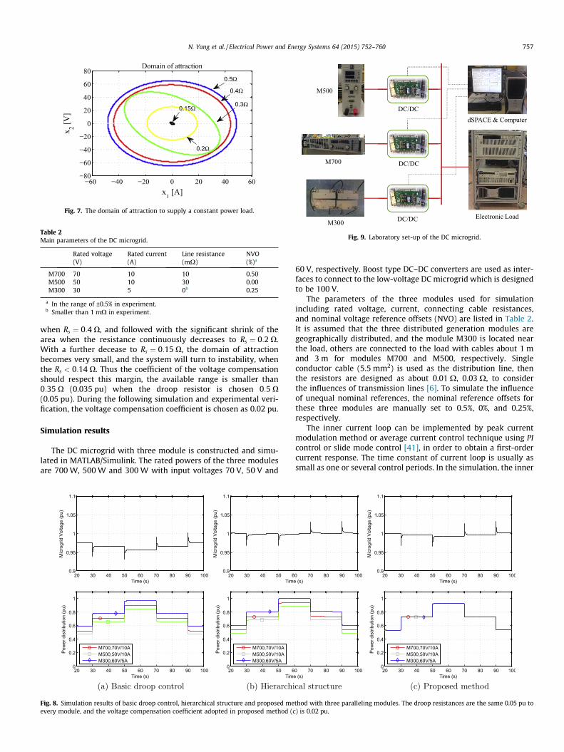
Fig. 7. The domain of attraction to supply a constant power load.
Table 2Main parameters of the DC microgrid.
Rated voltage(V)
Rated current(A)
Line resistance(mX)
NVO(%)a
M700 70 10 10 0.50M500 50 10 30 0.00M300 30 5 0b 0.25
a In the range of ±0.5% in experiment.b Smaller than 1 mX in experiment.
Fig. 9. Laboratory set-up of the DC microgrid.
N. Yang et al. / Electrical Power and Energy Systems 64 (2015) 752–760 757
when Rs ¼ 0:4 X, and followed with the significant shrink of thearea when the resistance continuously decreases to Rs ¼ 0:2 X.With a further decease to Rs ¼ 0:15 X, the domain of attractionbecomes very small, and the system will turn to instability, whenthe Rs < 0:14 X. Thus the coefficient of the voltage compensationshould respect this margin, the available range is smaller than0:35 X (0.035 pu) when the droop resistor is chosen 0:5 X(0.05 pu). During the following simulation and experimental veri-fication, the voltage compensation coefficient is chosen as 0.02 pu.
Simulation results
The DC microgrid with three module is constructed and simu-lated in MATLAB/Simulink. The rated powers of the three modulesare 700 W, 500 W and 300 W with input voltages 70 V, 50 V and
(a) Basic droop control (b) Hierarchi
Fig. 8. Simulation results of basic droop control, hierarchical structure and proposed meevery module, and the voltage compensation coefficient adopted in proposed method (c
60 V, respectively. Boost type DC–DC converters are used as inter-faces to connect to the low-voltage DC microgrid which is designedto be 100 V.
The parameters of the three modules used for simulationincluding rated voltage, current, connecting cable resistances,and nominal voltage reference offsets (NVO) are listed in Table 2.It is assumed that the three distributed generation modules aregeographically distributed, and the module M300 is located nearthe load, others are connected to the load with cables about 1 mand 3 m for modules M700 and M500, respectively. Singleconductor cable (5.5 mm2) is used as the distribution line, thenthe resistors are designed as about 0.01 X, 0.03 X, to considerthe influences of transmission lines [6]. To simulate the influenceof unequal nominal references, the nominal reference offsets forthese three modules are manually set to 0.5%, 0%, and 0.25%,respectively.
The inner current loop can be implemented by peak currentmodulation method or average current control technique using PIcontrol or slide mode control [41], in order to obtain a first-ordercurrent response. The time constant of current loop is usually assmall as one or several control periods. In the simulation, the inner
cal structure (c) Proposed method
thod with three paralleling modules. The droop resistances are the same 0.05 pu to) is 0.02 pu.
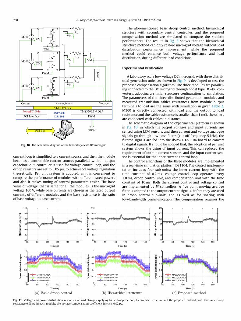
Fig. 10. The schematic diagram of the laboratory-scale DC microgrid.
758 N. Yang et al. / Electrical Power and Energy Systems 64 (2015) 752–760
current loop is simplified to a current source, and then the modulebecomes a controllable current sources paralleled with an outputcapacitor. A PI controller is used for voltage control loop, and thedroop resistors are set to 0.05 pu, to achieve 5% voltage regulationtheoretically. Per unit system is adopted, as it is convenient tocompare the performance of modules with different rated powersand also it makes tuning of control parameters easier. The basevalue of voltage, that is same for all the modules, is the microgridvoltage 100 V, while base currents are chosen as the rated outputcurrents of different modules and the base resistance is the ratioof base voltage to base current.
(a) Basic droop control (b) Hierarchi
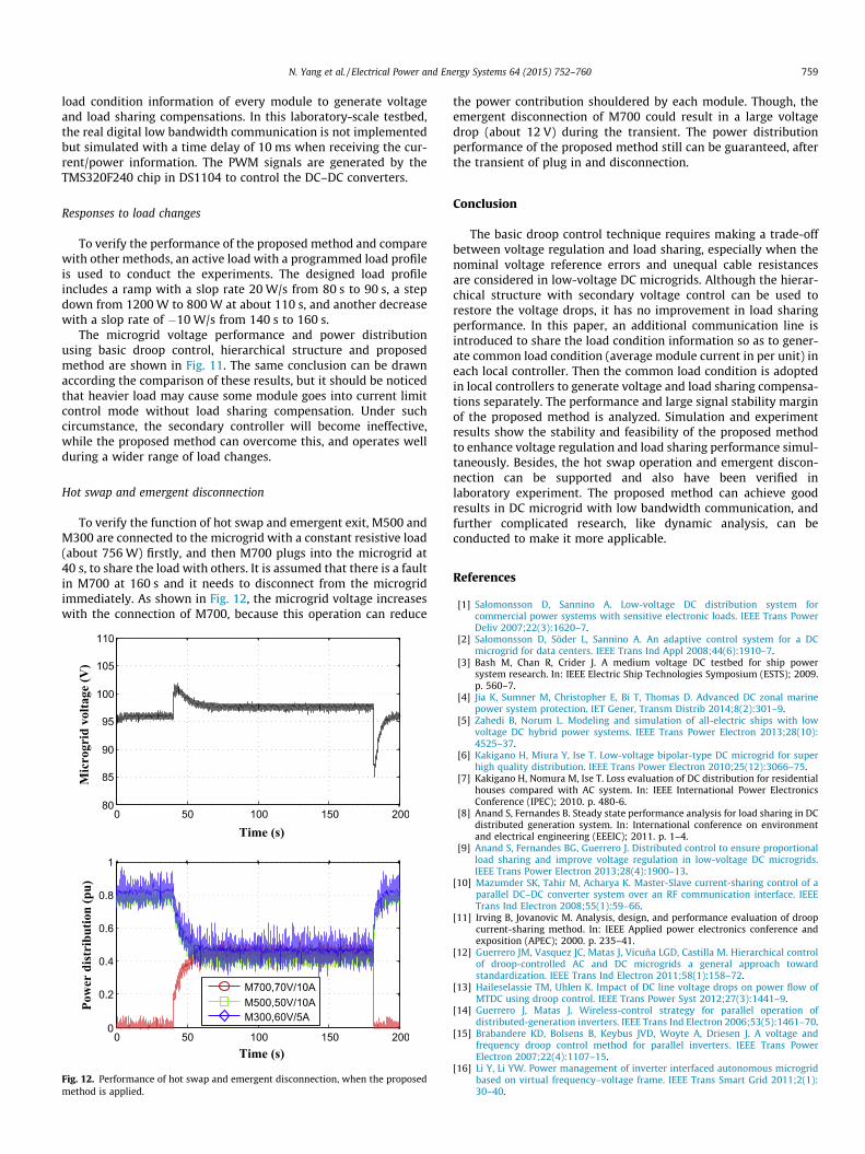
Fig. 11. Voltage and power distribution responses of load changes applying basic drooresistance 0.05 pu in each module, the voltage compensation coefficient in (c) is 0.02 pu
The aforementioned basic droop control method, hierarchicalstructure with secondary central controller, and the proposedcompensation method are simulated to compare the statisticperformances. The results in Fig. 8 shows that the hierarchicalstructure method can only restore microgrid voltage without loaddistribution performance improvement; while the proposedmethod could enhance both voltage performance and loaddistribution, during different load conditions.
Experimental verification
A laboratory scale low-voltage DC microgrid, with three distrib-uted generation units, as shown in Fig. 9, is developed to test theproposed compensation algorithm. The three modules are parallel-ing connected to the DC microgrid through boost type DC–DC con-verters, adopting a similar structure configuration to simulation.The parameters of the three distributed generation modules andmeasured transmission cables resistances from module outputterminals to load are the same with simulation in given Table 2.M300 is directly connected with load and the output to loadresistance and the cable resistance is smaller than 1 mX, the othersare connected with cables in distance.
The schematic diagram of the experimental platform is shownin Fig. 10, in which the output voltages and input currents aresensed using LEM sensors, and then current and voltage analoguesignals go through low-pass filters (cut-off frequency 5 kHz), thefiltered signals are fed into the dSPACE DS1104 board to convertto digital signals. It should be noticed that, the adoption of per unitsystem allows the using of input current. This can reduced therequirement of output current sensors, and the input current sen-sor is essential for the inner current control loop.
The control algorithms of the three modules are implementedin a real-time simulation platform DS1104. The control implemen-tation includes four sub-units: the inner current loop with thetime constant of 0.2 ms, voltage control loop operates every1.0 ms, droop control unit, and compensation unit with the timeconstant of 10 ms. Both the current control and voltage controlare implemented by PI controllers. A five point moving averagefilter is adapted to the output current signals, before they are usedin droop control sub-units and as well as for sharing withlow-bandwidth communication. The compensation requires the
cal structure (c) Proposed method
p method, hierarchical structure and the proposed method, with the same droop.
N. Yang et al. / Electrical Power and Energy Systems 64 (2015) 752–760 759
load condition information of every module to generate voltageand load sharing compensations. In this laboratory-scale testbed,the real digital low bandwidth communication is not implementedbut simulated with a time delay of 10 ms when receiving the cur-rent/power information. The PWM signals are generated by theTMS320F240 chip in DS1104 to control the DC–DC converters.
Responses to load changes
To verify the performance of the proposed method and comparewith other methods, an active load with a programmed load profileis used to conduct the experiments. The designed load profileincludes a ramp with a slop rate 20 W/s from 80 s to 90 s, a stepdown from 1200 W to 800 W at about 110 s, and another decreasewith a slop rate of �10 W/s from 140 s to 160 s.
The microgrid voltage performance and power distributionusing basic droop control, hierarchical structure and proposedmethod are shown in Fig. 11. The same conclusion can be drawnaccording the comparison of these results, but it should be noticedthat heavier load may cause some module goes into current limitcontrol mode without load sharing compensation. Under suchcircumstance, the secondary controller will become ineffective,while the proposed method can overcome this, and operates wellduring a wider range of load changes.
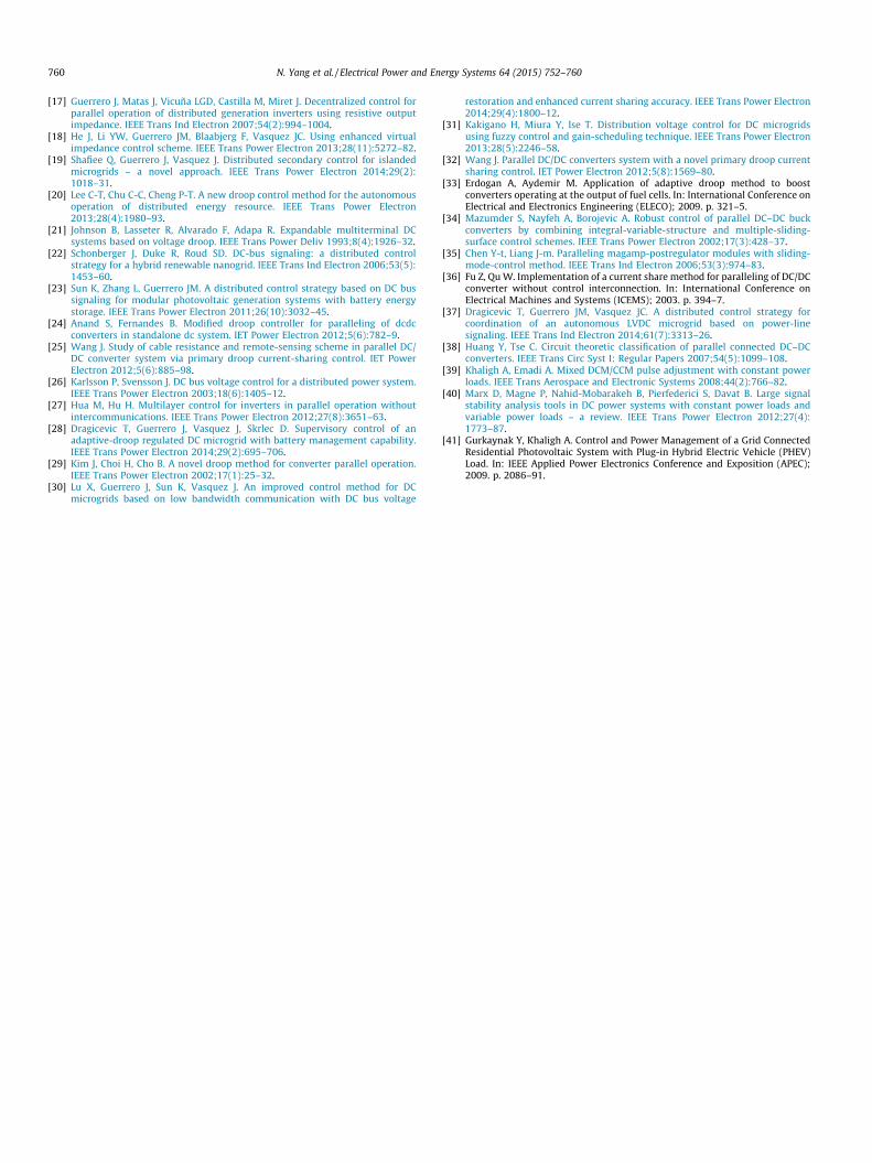
Hot swap and emergent disconnection
To verify the function of hot swap and emergent exit, M500 andM300 are connected to the microgrid with a constant resistive load(about 756 W) firstly, and then M700 plugs into the microgrid at40 s, to share the load with others. It is assumed that there is a faultin M700 at 160 s and it needs to disconnect from the microgridimmediately. As shown in Fig. 12, the microgrid voltage increaseswith the connection of M700, because this operation can reduce
Fig. 12. Performance of hot swap and emergent disconnection, when the proposedmethod is applied.
the power contribution shouldered by each module. Though, theemergent disconnection of M700 could result in a large voltagedrop (about 12 V) during the transient. The power distributionperformance of the proposed method still can be guaranteed, afterthe transient of plug in and disconnection.
Conclusion
The basic droop control technique requires making a trade-offbetween voltage regulation and load sharing, especially when thenominal voltage reference errors and unequal cable resistancesare considered in low-voltage DC microgrids. Although the hierar-chical structure with secondary voltage control can be used torestore the voltage drops, it has no improvement in load sharingperformance. In this paper, an additional communication line isintroduced to share the load condition information so as to gener-ate common load condition (average module current in per unit) ineach local controller. Then the common load condition is adoptedin local controllers to generate voltage and load sharing compensa-tions separately. The performance and large signal stability marginof the proposed method is analyzed. Simulation and experimentresults show the stability and feasibility of the proposed methodto enhance voltage regulation and load sharing performance simul-taneously. Besides, the hot swap operation and emergent discon-nection can be supported and also have been verified inlaboratory experiment. The proposed method can achieve goodresults in DC microgrid with low bandwidth communication, andfurther complicated research, like dynamic analysis, can beconducted to make it more applicable.
References
[1] Salomonsson D, Sannino A. Low-voltage DC distribution system forcommercial power systems with sensitive electronic loads. IEEE Trans PowerDeliv 2007;22(3):1620–7.
[2] Salomonsson D, Söder L, Sannino A. An adaptive control system for a DCmicrogrid for data centers. IEEE Trans Ind Appl 2008;44(6):1910–7.
[3] Bash M, Chan R, Crider J. A medium voltage DC testbed for ship powersystem research. In: IEEE Electric Ship Technologies Symposium (ESTS); 2009.p. 560–7.
[4] Jia K, Sumner M, Christopher E, Bi T, Thomas D. Advanced DC zonal marinepower system protection. IET Gener, Transm Distrib 2014;8(2):301–9.
[5] Zahedi B, Norum L. Modeling and simulation of all-electric ships with lowvoltage DC hybrid power systems. IEEE Trans Power Electron 2013;28(10):4525–37.
[6] Kakigano H, Miura Y, Ise T. Low-voltage bipolar-type DC microgrid for superhigh quality distribution. IEEE Trans Power Electron 2010;25(12):3066–75.
[7] Kakigano H, Nomura M, Ise T. Loss evaluation of DC distribution for residentialhouses compared with AC system. In: IEEE International Power ElectronicsConference (IPEC); 2010. p. 480-6.
[8] Anand S, Fernandes B. Steady state performance analysis for load sharing in DCdistributed generation system. In: International conference on environmentand electrical engineering (EEEIC); 2011. p. 1–4.
[9] Anand S, Fernandes BG, Guerrero J. Distributed control to ensure proportionalload sharing and improve voltage regulation in low-voltage DC microgrids.IEEE Trans Power Electron 2013;28(4):1900–13.
[10] Mazumder SK, Tahir M, Acharya K. Master-Slave current-sharing control of aparallel DC–DC converter system over an RF communication interface. IEEETrans Ind Electron 2008;55(1):59–66.
[11] Irving B, Jovanovic M. Analysis, design, and performance evaluation of droopcurrent-sharing method. In: IEEE Applied power electronics conference andexposition (APEC); 2000. p. 235–41.
[12] Guerrero JM, Vasquez JC, Matas J, Vicuña LGD, Castilla M. Hierarchical controlof droop-controlled AC and DC microgrids a general approach towardstandardization. IEEE Trans Ind Electron 2011;58(1):158–72.
[13] Haileselassie TM, Uhlen K. Impact of DC line voltage drops on power flow ofMTDC using droop control. IEEE Trans Power Syst 2012;27(3):1441–9.
[14] Guerrero J, Matas J. Wireless-control strategy for parallel operation ofdistributed-generation inverters. IEEE Trans Ind Electron 2006;53(5):1461–70.
[15] Brabandere KD, Bolsens B, Keybus JVD, Woyte A, Driesen J. A voltage andfrequency droop control method for parallel inverters. IEEE Trans PowerElectron 2007;22(4):1107–15.
[16] Li Y, Li YW. Power management of inverter interfaced autonomous microgridbased on virtual frequency–voltage frame. IEEE Trans Smart Grid 2011;2(1):30–40.
760 N. Yang et al. / Electrical Power and Energy Systems 64 (2015) 752–760
[17] Guerrero J, Matas J, Vicuña LGD, Castilla M, Miret J. Decentralized control forparallel operation of distributed generation inverters using resistive outputimpedance. IEEE Trans Ind Electron 2007;54(2):994–1004.
[18] He J, Li YW, Guerrero JM, Blaabjerg F, Vasquez JC. Using enhanced virtualimpedance control scheme. IEEE Trans Power Electron 2013;28(11):5272–82.
[19] Shafiee Q, Guerrero J, Vasquez J. Distributed secondary control for islandedmicrogrids – a novel approach. IEEE Trans Power Electron 2014;29(2):1018–31.
[20] Lee C-T, Chu C-C, Cheng P-T. A new droop control method for the autonomousoperation of distributed energy resource. IEEE Trans Power Electron2013;28(4):1980–93.
[21] Johnson B, Lasseter R, Alvarado F, Adapa R. Expandable multiterminal DCsystems based on voltage droop. IEEE Trans Power Deliv 1993;8(4):1926–32.
[22] Schonberger J, Duke R, Roud SD. DC-bus signaling: a distributed controlstrategy for a hybrid renewable nanogrid. IEEE Trans Ind Electron 2006;53(5):1453–60.
[23] Sun K, Zhang L, Guerrero JM. A distributed control strategy based on DC bussignaling for modular photovoltaic generation systems with battery energystorage. IEEE Trans Power Electron 2011;26(10):3032–45.
[24] Anand S, Fernandes B. Modified droop controller for paralleling of dcdcconverters in standalone dc system. IET Power Electron 2012;5(6):782–9.
[25] Wang J. Study of cable resistance and remote-sensing scheme in parallel DC/DC converter system via primary droop current-sharing control. IET PowerElectron 2012;5(6):885–98.
[26] Karlsson P, Svensson J. DC bus voltage control for a distributed power system.IEEE Trans Power Electron 2003;18(6):1405–12.
[27] Hua M, Hu H. Multilayer control for inverters in parallel operation withoutintercommunications. IEEE Trans Power Electron 2012;27(8):3651–63.
[28] Dragicevic T, Guerrero J, Vasquez J, Skrlec D. Supervisory control of anadaptive-droop regulated DC microgrid with battery management capability.IEEE Trans Power Electron 2014;29(2):695–706.
[29] Kim J, Choi H, Cho B. A novel droop method for converter parallel operation.IEEE Trans Power Electron 2002;17(1):25–32.
[30] Lu X, Guerrero J, Sun K, Vasquez J. An improved control method for DCmicrogrids based on low bandwidth communication with DC bus voltage
restoration and enhanced current sharing accuracy. IEEE Trans Power Electron2014;29(4):1800–12.
[31] Kakigano H, Miura Y, Ise T. Distribution voltage control for DC microgridsusing fuzzy control and gain-scheduling technique. IEEE Trans Power Electron2013;28(5):2246–58.
[32] Wang J. Parallel DC/DC converters system with a novel primary droop currentsharing control. IET Power Electron 2012;5(8):1569–80.
[33] Erdogan A, Aydemir M. Application of adaptive droop method to boostconverters operating at the output of fuel cells. In: International Conference onElectrical and Electronics Engineering (ELECO); 2009. p. 321–5.
[34] Mazumder S, Nayfeh A, Borojevic A. Robust control of parallel DC–DC buckconverters by combining integral-variable-structure and multiple-sliding-surface control schemes. IEEE Trans Power Electron 2002;17(3):428–37.
[35] Chen Y-t, Liang J-m. Paralleling magamp-postregulator modules with sliding-mode-control method. IEEE Trans Ind Electron 2006;53(3):974–83.
[36] Fu Z, Qu W. Implementation of a current share method for paralleling of DC/DCconverter without control interconnection. In: International Conference onElectrical Machines and Systems (ICEMS); 2003. p. 394–7.
[37] Dragicevic T, Guerrero JM, Vasquez JC. A distributed control strategy forcoordination of an autonomous LVDC microgrid based on power-linesignaling. IEEE Trans Ind Electron 2014;61(7):3313–26.
[38] Huang Y, Tse C. Circuit theoretic classification of parallel connected DC–DCconverters. IEEE Trans Circ Syst I: Regular Papers 2007;54(5):1099–108.
[39] Khaligh A, Emadi A. Mixed DCM/CCM pulse adjustment with constant powerloads. IEEE Trans Aerospace and Electronic Systems 2008;44(2):766–82.
[40] Marx D, Magne P, Nahid-Mobarakeh B, Pierfederici S, Davat B. Large signalstability analysis tools in DC power systems with constant power loads andvariable power loads – a review. IEEE Trans Power Electron 2012;27(4):1773–87.
[41] Gurkaynak Y, Khaligh A. Control and Power Management of a Grid ConnectedResidential Photovoltaic System with Plug-in Hybrid Electric Vehicle (PHEV)Load. In: IEEE Applied Power Electronics Conference and Exposition (APEC);2009. p. 2086–91.