
Adaptive Protection System for Microgrids: Protection practices of a functional microgrid system
15
2325-5987/14/$31.00©2014 IEEE ISTRIBUTED ENERGY RESOURCES (DERs) OFFER ON-SITE generation at consumption points, which are expected to change the conventional concept of central power gener- ation. DER integration reduces transmission losses and enhances the operation reliability of distribution sys- tems. However, distribution systems are traditionally designed as pas- sive networks in which large DER penetrations representing bidirectional power flows and topology-dependent fault currents could affect protection devices, cause danger to the maintenance personnel, and result in uncontrollable under-/overvoltage and frequency. IEEE Standard 1547 requires DER units to stop energizing the distribution system when the system is de-energized due to faults. Microgrids are introduced to address the issues with the economics and the resilience of power delivery systems. A microgrid is a small elec- tric power system, which is connected to the utility grid through the point of common coupling (PCC), and uses on-site DERs for supplying all or some portions of local demands. When connected to the utility grid, microgrid loads are supplied by both the utility grid and on-site generation. From the utility grid side, a microgrid is seen as an aggregated controllable load. A key feature of the microgrid operation includes its seamless islanding from the utility grid and ability to be self-controlled in island mode. Once a fault affects a distribution network, local microgrids can enhance the power system reliability by switching to island mode as local DER units continue to supply the microgrid loads. IEEE Electrification Magazine / MARCH 2014 66 2325-5987/14/$31.00©2014IEEE Digital Object Identifier 10.1109/MELE.2013.2297031 Date of publication: 18 March 2014 By Liang Che, Mohammad E. Khodayar, and Mohammad Shahidehpour DOG © CAN STOCK PHOTO/3DCLIPARTSDE. MICROGRID COURTESY OF MOHAMMAD SHAHIDEHPOUR. Protection practices of a functional microgrid system.
Transcript of Adaptive Protection System for Microgrids: Protection practices of a functional microgrid system

2325-5987/14/$31.00©2014 IEEE
istributed energy resources (ders) offer on-site generation at consumption points, which are expected to change the conventional concept of central power gener-ation. der integration reduces transmission losses and enhances the operation reliability of distribution sys-
tems. However, distribution systems are traditionally designed as pas-sive networks in which large der penetrations representing bidirectional power flows and topology-dependent fault currents could affect protection devices, cause danger to the maintenance personnel, and result in uncontrollable under-/overvoltage and frequency. ieee standard 1547 requires der units to stop energizing the distribution system when the system is de-energized due to faults.
Microgrids are introduced to address the issues with the economics and the resilience of power delivery systems. A microgrid is a small elec-tric power system, which is connected to the utility grid through the point of common coupling (Pcc), and uses on-site ders for supplying all or some portions of local demands. When connected to the utility grid, microgrid loads are supplied by both the utility grid and on-site generation. from the utility grid side, a microgrid is seen as an aggregated controllable load. A key feature of the microgrid operation includes its seamless islanding from the utility grid and ability to be self-controlled in island mode. once a fault affects a distribution network, local microgrids can enhance the power system reliability by switching to island mode as local der units continue to supply the microgrid loads.
IEEE Electr i f icat ion Magazine / MARCH 201466 2325-5987/14/$31.00©2014IEEE
Digital Object Identifier 10.1109/MELE.2013.2297031 Date of publication: 18 March 2014
By Liang Che, Mohammad E. Khodayar, and Mohammad Shahidehpour
Dog © Can StoCk Photo/3DCliPartSDE. MiCrogriD CourtESy of MohaMMaD ShahiDEhPour.
Adaptive Protection System
for Microgrids
D
Protection practices of a functional microgrid system.

IEEE Electr i f icat ion Magazine / MARCH 2014 67
despite the numerous advantages of using microgrids, there are technical challenges regarding the control and protection of microgrids. one of the prominent challenges in microgrid operations is the design of a proper protec-tion scheme for microgrids. the integration of ders and novel topologies embedded in microgrids would challenge the characteristics of protection schemes in microgrids as compared with those of conventional distribution sys-tems. the conventional protection strategies in distribu-tion systems rely on the radial topology of distribution networks with the supply located at one end. in this con-figuration, the fault current is provided by the utility grid with protective device (Pd) settings adjusted accordingly to localize the impact of faults. Pds are coordinated based
on unidirectional power flows from the feeder toward loads in radial distribution networks, in which fault cur-rents are lower as fault locations get farther from feeders. However, these unidirectional characteristics change in microgrids. der units located in microgrids can increase fault currents, change fault current flow paths, result in bidirectional power flows, and affect Pd operations. the inclusion of der units with power electronic interfaces, such as converters, would limit fault currents and desen-sitize Pds to faults, especially in island mode. the large difference between fault currents in grid-connected and island modes presents new challenges in microgrid fault protections. Moreover, the microgrid topology can be looped, meshed, or mixed networks, which could result in

IEEE Electr i f icat ion Magazine / MARCH 201468
more complex fault current paths and affect protection strategies in microgrids.
in this article, protection system challenges in microgrids are discussed and protection practices in the context of a functional microgrid system at the illinois institute of technology (iit) are presented. We address the structure and design of the iit microgrid and analyze technical approaches for protecting the iit microgrid in grid-connected and island modes.
Challenges in Microgrid Protection Systemsconventional protection schemes for radial distribution networks cannot be applied to microgrids without major modifications. such modifications would require address-ing the impact of der integration, microgrid topology, and fault current levels in grid-connected and island modes. in this section, the challenges and possible solutions to microgrid protection are discussed.
Challengesthe integration of der units would impose major challenges in microgrid protection schemes. the conventional distribu-tion system protection is designed for radial distribution net-works that include feeders at one end with high fault currents. in radial distribution networks, fault currents always flow downstream, i.e., from utility feeders toward fault locations. As a single source of power generation, utility feeders provide high fault currents, which trigger Pds along feeder paths. However, traditional protection schemes face the following fundamental challenges in microgrids.
Fault Current-Level Modificationsfault currents depend on microgrid operation modes. in grid-connected mode, utilities contribute to microgrid fault currents while, in islanded mode, microgrids’ potential fault currents are lower. the fault current injection capabil-ity of ders with power electronic interfaces is limited to twice their rated currents, and lower fault currents would not trip overcurrent (oc) relays. in traditional distribution
networks, fault currents decrease as feeder impedances increase when fault points shift downward along feeder paths; however, microgrid ders contribute to fault cur-rents along feeder paths. der units, especially generators with rotating prime movers, such as synchronous or induction generators, would have higher contributions to fault currents when compared with ders with power elec-tronic interfaces. As fault current paths could be different in grid-connected and island modes, the two operation modes would require different relay settings. As a result, fixed settings for microgrid relays may become impractical as the dynamic behavior of ders may also affect the coor-dinated settings of relays.
Impact of DERs on the Operation of Protective Devicesder units have plug-and-play characteristics in microgrids, which may require modifications to traditional relay set-tings. in such cases, der locations and fault currents would determine precise relay settings. the impact of der integration on Pd operations is summarized in the follow-ing two categories:
xx Malfunction of PDs due to downstream faults: in a downstream fault, shown in figure 1(a), utility grid and der unit currents (Ig and ,IDER respectively) con-tribute to the total fault current. if IDER is large enough, Ig will be reduced because of a higher voltage contrib-uted by IDER at Pcc. thus, Pd1 may not trip because of a lower fault current even though feeder 1 experienc-es a higher fault current.xx Sympathetic tripping: in figure 1(b), Pd3 should trip to clear the fault. However, if the der unit contribution to the fault current is large, Pd2 may trip in response to high current ,IDER which would disconnect feeder 2 from the utility grid.
Impact of Microgrid Topology on the Coordination of Protective Devicesthe looped or meshed networks in microgrids will affect fault current magnitudes and directions. for example, the fault current in a loop is divided between two parallel paths. Hence, Pds on the upstream feeder may have cur-rents that are twice as large as that in each fault path within a loop. Accordingly, looped or meshed structures in microgrids could impact the Pd coordination.
Possible Solutions for Relay Coordination
Balancing DER Technologies for OC ProtectionA possible solution to overcome low contributions of der units to fault currents in microgrids is to balance der unit contributions with those of other generation technologies by introducing generating units with higher fault currents to increase total fault currents in microgrids to proper lev-els that could be detected by oc protection systems. syn-chronous generators, including permanent magnet
UtilityGrid
UtilityGrid
MissingOperation
SympatheticTrippingIg Ig
IDER IDER
DERDER
Feeder 1 Feeder 1 Feeder 2
PD1 PD1
PD2 PD2
PD3
(a) (b)
Figure 1. The impact of DER units on relay operation. (a) The malfunction of PDs due to downstream faults and (b) the sympathetic tripping of PD.

IEEE Electr i f icat ion Magazine / MARCH 2014 69
synchronous generators (PMsgs), and fly wheels are suit-able choices for increasing fault currents in microgrids.
Differential Protection Schemesdifferential protection schemes are based on coupled dif-ferential directional relays that can accurately locate and isolate faults without affecting other components in distri-bution systems. differential protection schemes, which incorporate traditional protection technologies, are suited for microgrid protections in both grid-connected and island modes. differential protection schemes are either central-ized (monitored and coordinated by central controllers) or localized (based on local communications among relays). in centralized schemes, central controllers monitor the microgrid network topology and operation settings of Pds and send tripping commands to Pds once faults are detect-ed. centralized schemes provide more accurate results with rather unacceptable time delays for performing the compu-tations required by the central controllers. Localized schemes, which are more readily adopted for industry applications, allow for direct communication among relays with the fastest response to faults.
Adaptive Protection Schemesthe difference between fault currents in grid-connected and island modes would necessitate adaptive protection
schemes in microgrids. Adaptive schemes would include two sets of relay settings, one for grid-connected and the other for island mode. relays would select proper settings when microgrids switch their operation modes. in island mode, the time-oc (toc) characteristic curve of relays will be shifted to instantaneous and/or definite-time oc set-tings to adapt to lower fault currents. Moreover, adaptive protection schemes would automatically adjust the relay settings according to the network operating state. for example, a voltage restraint oc protection scheme would reduce the time dials (tripping delays) of relays in cases of large voltage depressions.
Protection Schemes Based on Other Parameter MeasurementsVoltage- or harmonic-based detection techniques are con-sidered as alternatives once low fault currents render tra-ditional oc protection schemes impractical in island mode. the voltage-based protection schemes would locate faults by detecting the “d-q” components of voltage distur-bances based on the Park transformation. However, the voltage-based detection schemes may not provide accu-rate fault detections, and undesirable time delays would be introduced by additional computation and filtering. thus, this protection scheme is usually used in combina-tion with other fault-detection and protection schemes.
Utility Grid12.47 kV
PCCNorthSubstation
SouthSubstation
4.16 kV 4.16 kV
Feeder Switch-B Feeder Switch-A
PV
Eng. 1
Battery
LS
Wind Stuart PV
PV PV
Gas-TurbineSynchronous
Generator
CTA
2C
TA1
Van
derC
ook
Loop 1
Vis
ta-D
Vis
ta-B
Vis
ta-A
Vis
ta-E
Vista-C
Loop 2 Loop 3 Loop 7
B A
2 1
13
22
13
2
13
2
2
1
1
3
3
Load-Way and Load-Way PD
Loop and Loop PD
Load-Feeder and Load-Feeder PD
Substation PD
Substation Bus
Utility Grid12.47 kV
PCCNorthSubstation
SouthSubstation
4.16 kV 4.16 kV
eeder Switch-B Feeder Switch-A
PV
Eng. 1
attery
LS
Wi d St t PV
PV PV
Gas-TurbinSynchronou
Generator
CTA
2C
TA1
Van
derC
ook
Loop 1
Vis
ta-D
Vis
ta-B
Vis
ta-A
Vis
ta-E
Vista-C
Loop 2 Loop 3 Loop 7
BB AA
22 11
1133
2222
1133
22
1133
22
22
11
11
33
33
Figure 2. The IIT microgrid protection system.

IEEE Electr i f icat ion Magazine / MARCH 201470
IIT Microgrid Topology and Componentsiit owns and operates its campus underground distribution network. figure 2 shows the topology of the 4.16-kV microgrid, which is fed through two substations. the north substation (ns) and south substation (ss) are connected through a cable to facilitate seamless operation in case of a failure in one of the utility feeders within the iit substa-tions. the iit microgrid features a high-reliability distribu-tion system (Hrds) with phasor measurement units to enhance reliable operation of the campus microgrid. seven distribution loops are implemented by integrating Hrds Vista switches, which connect ders [gas turbines, solar photovoltaic (PV), wind generation, and battery storage] with load entities (building loads and charging stations). the iit microgrid is equipped with building automation technologies (building controllers, subbuilding controllers, and controllable loads) for energy efficiency and demand response throughout the microgrid.
Vista-e in figure 2 is a three-way switch in loop 1. two ways, which are denoted as loop-ways of a Vista switch (Vis-ta-e-1 and Vista-e-2), are equipped with loop Pds. the third way (Vista-e-3), denoted as a load-way, is equipped with a load-way Pd, which connects the loads or der units to the microgrid distribution network. the individual loops are con-nected to the substations via a pair of loop-feeder Pds (A and b in figure 2). the substation is supplied by the 12.47-kV/4.16-kV delta-wye transformer via substation Pds. the natural gas turbine synchronous generator is connected to the ss through generator Pds, and the ns and ss are connected by a cross-tie cable.
Adaptive Protection Schemes in the IIT Microgrid
Hierarchical Protection Scheme for the Microgridthe hierarchical protection scheme of the iit microgrid is shown in figure 3. the scheme is based on localized dif-ferential protections in seven loops and four coordinated protection levels, which are implemented by communica-tion-assisted digital directional relays and Hrds switches. the fundamentals of the effective protection scheme at the iit microgrid are categorized in the following sections.
Balancing the DER Technologies to Contribute Sufficient Fault Currents in Island Modein the iit microgrid, the synchronous generator can pro-vide sufficient fault currents in island mode. two cases are simulated in power system computer-aided design (PscAd) to verify fault current contributions of the syn-chronous generator. the first case considers island mode, in which the synchronous generator operates in conjunc-tion with other ders, while in the second case, the syn-chronous generator operates in parallel with the utility grid to serve the 8 MW of campus load. in each case, a sin-gle-phase-to-ground fault is applied on different sections of the loops. the fault currents associated with fault loca-tions are listed in table 1. since the peak load supplied by a single loop is fewer than 3 MW, the maximum current in normal operation that passes through the cables within each loop is fewer than 0.25 kA when both loop-feeder breakers “A” and “b” are closed (see figure 2). once a loop-feeder breaker opens, the maximum current in normal
Microgrid Protection Principle
ProtectionScheme
ProtectionCoordination
ProtectiveComponents
MultilevelProtection Strategy
MicrogridLevel
Substation Protection andThermal Generation Protection
LocalizedDifferentialProtectionScheme
NondirectionalOC Scheme
DirectionalOC Scheme
Loop-FeederLevel
Loop-FeederProtection
Loop-FeederProtection
LoopDifferential
Load-WayProtection
Load-WayProtection
DirectionalDigitalRelays
and HRDSSwitches
Non-directional
Relays
LoopDifferential
LoopLevel
Load-WayLevel
Loop-1 Loop-7
Figure 3. The hierarchical protection principle of the IIT microgrid.

IEEE Electr i f icat ion Magazine / MARCH 2014 71
operation flowing through the cables in each loop is fewer than 0.5 kA. thus, the fault current magnitude in island mode (case 1 in table 1) is adequate to trigger oc Pds. Moreover, loops 1–3 are directly connected to ns while loops 4–7 are connected to the ss, so the utility grid con-tributes more to fault currents through ns for faults locat-ed in loops 1–3 than those located in loops 4–7 as shown in table 1. similar-ly, the utility grid would provide higher currents through the ss to faults located in loops 4–7 than those locat-ed in loops 1–3.
Localized Differential Protection Scheme Implemented by Communication-Assisted Directional OC Relaysthe differential protection scheme can be centralized or localized. the iit microgrid uses the localized differential protection scheme as the centralized control suffers from time delays. the Vista switches installed within the loops are equipped with communication-assisted directional oc relays. the two relays at each end of a loop section are equipped with optical fiber communication, which facilitates fast (2 ms) and highly reliable communication capability between them.
Adaptive Relay Settings for Grid-Connected and Island ModesAs the fault current level shown in table 1 reduced in island mode, the communication-assisted oc relays in the iit microgrid can change the settings upon receiving the islanding signal from the master controller (Mc). the relays switch to instantaneous/definite-time oc protec-tion scheme, considering the fault current levels in island mode, to ensure a fast response to lower fault currents.
Loop Structure to Facilitate Hierarchical Protection and Increase Service Reliabilitythe loop structure provides an uninterrupted electricity sup-ply when one section of the loop is isolated because of a fault. the iit microgrid features a hierarchical protection structure to enhance the protection reliability. the loop Pds in figure 2 not only clear the faults within the loop without any interruption to loads but also provide backup protection to the load-way Pds in case a load-way fault occurs. if the load-way and loop-level pro-tection fails to clear the faults within a loop, the entire loop is isolated quickly by respec-tive loop-feeder relays; thus, an uninter-rupted and reliable supply to other healthy loops is ensured. the hierarchical protec-tion strategy at the iit microgrid is present-ed in the “Protection strategy” section.
Protection Strategyin figure 3, the microgrid protection is divided into four levels: the load-way level, loop level, loop-feeder level, and microgrid level. the protection devices and operation rules in each level are summarized in table 2. the detailed protection strategy of each level will be discussed next in
this section.
Load-Way Protectionthe green blocks in figure 2 denote load-way directional oc digital relays, which clear load-way faults. figure 4 shows a section of loop 1 with Vista switches b, c, and d. in this figure, the black dashed arrow indicates the posi-tive flow direction on each loop Pd. the red, bold arrow denotes the fault current direction. in this figure, the load-way protection and its backup protection are shown. in figure 4(a), once a fault at the load-way of Vista switch c is cleared by the load-way Pd
(c3), the campus building connected to the Vista switch c will be isolated. if the breaker at c3 fails, relay c3 will immediately send transfer trip signals to c1 and c2, which are mounted on the same Vista switch. figure 4(b) shows the pair of loop Pds in Vista c (c1 and c2), which provide backup protections for c3. should this backup protection operate, the buildings connected to Vista c will be isolated. the load-way Pds can be programmed up to four shots of automatic reclosing. the load-shedding and other control schemes could also be implemented on the load-way pro-tection level based on under/overvoltage and under/over-frequency functions of these relays.
Loop Protectionthe communication-assisted digital directional relays (blue blocks) in figure 2 are implemented on the loop-way of Vista switches to provide differential protections at loop levels. figure 5 shows the same section shown in figure 4 to present the loop protection schemes when faults occur in a loop section between Vista switches c and d. in this figure, there is a communication channel between cou-pled relays on both sides of each cable segment (c1 and
TABLE 1. The Fault Currents (rms) at the IIT Microgrid.
Fault Location
Case 1 :Islanded Mode
Case 2 :Grid-Connected Mode
PCC at NS PCC at SS
Loops 1–3 3 kAa ~ 4 kAb 12 kAa ~ 15 kAb 8 kAa ~ 9 kAb
Loops 4–7 8 kAa~ 9 kAb 12 kAa~ 15 kAb
aFault current is lower when the fault is close to the middle point of the loop. bFault current is higher when the fault is close to the loop feeder. (All currents are calculated for single-phase to ground fault.)
Microgrids are introduced to address the issues with the economics and the resilience of power delivery systems.
IEEE Electr i f icat ion Magazine / MARCH 201472
d2) for facilitating the permissive overreaching transfer trip (Pott) protection scheme.
in figure 5(a), when a fault occurs in a segment within a loop, relays within the loop will sense the fault current. the relays sensing the positive directional fault current (d2, c1, and b1) will send permissive signals to their cou-pled relays (c1, d2, and c2), respectively. in this case, only the coupled relays d2 and c1 will clear the fault because each would sense a positive fault current and receive permissive signals. the tripping crite-rion is because both coupled relays detect positive directional fault cur-rent, which indicates that the fault has occurred within the loop section located between them. figure 5(a) shows that once d2 and c1 cleared the fault, the loop is converted into two parallel feeders and the loop structure is changed to a radial net-work without any load interruptions.
the backup protection operates if a Pott scheme fails (e.g., breaker at c1 fails). in figure 5(b), once the breaker failure is detected, c1 will send a transfer trip signal to c2 to open the breaker at c2. Here, an outage will occur in buildings fed by Vista switch c while other load points in the same loop will not be affected. directional
relays eliminate traditional coordination time intervals for primary protections and facilitate an accurate fault-locating scheme within a loop. the load-way and loop relays are high-speed digital relays with an operating time of fewer than 1 cycle (exclusive of the relay’s time delay and the breaker operating time). thus, very high-speed and accu-rate protections are implemented at the load-way and loop protection levels of the iit microgrid.
Loop-Feeder Protectiontable 2 shows that the loop-feeder pro-tection is the upper level of the loop protection, which acts as a backup pro-tection for the entire loop. When a fault in the load-way or loop results in the failure of load-way and loop pro-tection schemes (e.g., loss of commu-nication between Pds or any Pd failure), the loop on outage will be iso-lated by the backup protection provid-ed by loop-feeder Pds. Loop-feeder relays (purple blocks in figure 2) are nondirectional oc relays, which are set to be slower than load-way and loop relays and faster than substation relays. the proposed setting prevents
nuisance tripping and ensures that faulted loops are iso-lated before substation relays get to operate.
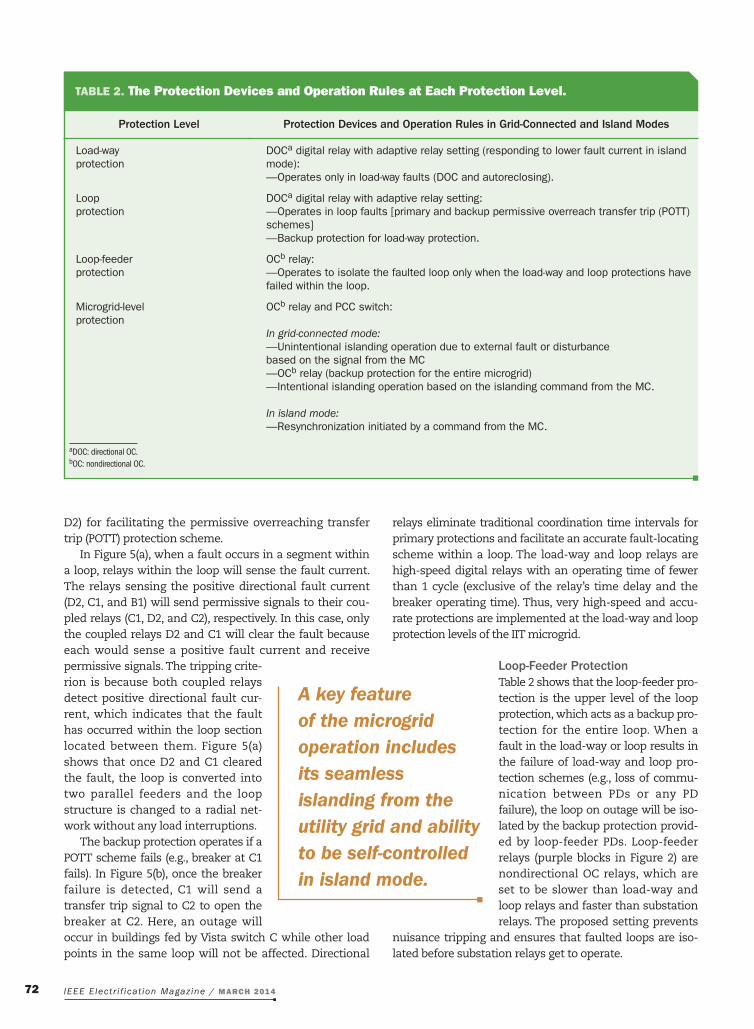
TABLE 2. The Protection Devices and Operation Rules at Each Protection Level.
Protection Level Protection Devices and Operation Rules in Grid-Connected and Island Modes
Load-wayprotection
DOCa digital relay with adaptive relay setting (responding to lower fault current in island mode):—Operates only in load-way faults (DOC and autoreclosing).
Loopprotection
DOCa digital relay with adaptive relay setting:—Operates in loop faults [primary and backup permissive overreach transfer trip (POTT) schemes]—Backup protection for load-way protection.
Loop-feederprotection
OCb relay:—Operates to isolate the faulted loop only when the load-way and loop protections have failed within the loop.
Microgrid-levelprotection
OCb relay and PCC switch:
In grid-connected mode:—Unintentional islanding operation due to external fault or disturbancebased on the signal from the MC—OCb relay (backup protection for the entire microgrid)—Intentional islanding operation based on the islanding command from the MC.
In island mode:—Resynchronization initiated by a command from the MC.
aDOC: directional OC. bOC: nondirectional OC.
A key feature of the microgrid operation includes its seamless islanding from the utility grid and ability to be self-controlled in island mode.

IEEE Electr i f icat ion Magazine / MARCH 2014 73
Microgrid-Level Protectionthe microgrid-level protection includes Pds for substa-tions and synchronous generators, which are equipped with nondirectional oc relays for backup protection. When the microgrid is in grid-connected mode, the oc relay and the Pcc switch located at the substation can operate in one of the following scenarios:
xx Unintentional islanding as a result of external disturbanc-es: this operation is to protect the iit microgrid against utility network outages as shown in figure 6. in the case of external outages, the utility Pd (Pd1 in figure 16) would trip to isolate the fault, leading to an uninten-tional islanding of the iit microgrid. once any utility-side voltage and frequency deviations are detected, the microgrid Mc will send a command to open the Pcc switch and isolate the microgrid.
Figure 5. The (a) loop POTT and (b) backup scheme.
D1 2
3
C1 2
3
B1 2
3
D1 2
3
C1 2
3
B1 2
3
D1 2
3
C1 2
3
B1 2
3
D1 2
3
C1 2
3
B1 2
3Tripped Failed
Failed
BackupTripped
Outage Outage
TransferTrip
(a) (b)
Figure 4. The (a) load-way and (b) backup protection.
D1
32
D1
32
D1
32
C1
32
C
13
2
B1
32
B1
32
13
2 13
2
POTT POTTC B
D1
32 1
32 1
32
C B
Tripped Tripped
Failed
FailedTripped
BackupTripped
Outage
TransferTrip
332 1
332
D1
332
133
2
C
133
2
133
B1
33
133
2 133
2
D
332 1
332 1
332
C B
Tripped Tripped
Failed
FailedTripped
BackupTripped
Outage
(a) (b)
POTT
External Fault orDisturbance on Utility
Microgrid
Signalfrom MC
Substation Relayand PCC Switch
Utility PD
Figure 6. The unintentional islanding of the microgrid due to a utility disturbance.

IEEE Electr i f icat ion Magazine / MARCH 201474
xx Nondirectional OC relay: if the primary protection fails to clear a microgrid fault or the Pcc switch does not respond to the Mc’s command to isolate a utility fault, the Pcc switch will ultimately open in response to the substation oc relay. this relay should have a suffi-cient time-delay for the operation of all protection schemes in the load-way, loop, and loop-feeder levels.xx Intentional islanding and resynchronization initiated by the MC: this operation is controlled by the Mc for intentional islanding of the microgrid and does not apply to any faults.
in the iit, two synchronous generators are directly con-nected to the ss. in island mode, a synchronous generator should remain connected, at least for a short period, to provide sufficient fault currents for Pd operations at other protection levels; hence, the oc relay of synchronous generator has a longer time delay than that of the substa-tion protection.
DER Switchesfigure 7 shows that renewable energy resources (PV and wind) are connected via a controlled der switch to the load-way Pd of Vista switches. in this figure, once the relay e3 detects the microgrid isolation, it will send a transfer trip signal to the der switch to open. this function prevents an uncontrollable under-/overvoltage or frequen-cy according to ieee standard 1547, which requires der units to be disconnected when the microgrid is de- energized. unlike renewable energy resources, the battery storage supplies the campus load when there is a loop fault. if a campus building or loop connected to the battery storage is isolated, the Mc will send signals to dis-charge the battery storage in the building or loop. the duration of battery storage discharge is dependent on the available energy at the isolation instant.
Protection Coordination in the IIT Microgrid
Coordination Based on Operation Curves of Relaysfigure 8 shows the toc curves of relays in grid-connected and island modes. in this figure, load and loop curves denote the toc curves for load-way and loop relays, which clear the load-way and loop faults, respectively. the feeder and substation curves denote the toc curve for the nondi-rectional oc relays at the loop-feeders and substation. based on the adaptive protection scheme discussed in the “Hierarchical Protection scheme for the Microgrid” section, once the microgrid changes its operation to island mode, the Mc would send a signal to the load-way and loop relays to switch to the instantaneous/definite-time oc scheme as shown in figure 8(b). this enables the load-way and loop relays to respond to lower fault currents in the island mode.
Coordination Considering Special Cases in Loopssince the fault on a closed-loop iit microgrid system will always be fed through two paths from substations, the relay coordination for a looped distribution network dif-fers from that of a radial network. to evaluate the protec-tion coordination in a loop, two extreme cases are investigated in loop 1, as shown in figure 9.
1) Equidistance loop fault: the equidistance loop faults occur half-way between the loop-feeder breakers (e.g., at point 1 in figure 9). in this case, as the fault current is split equally between the two paths in the loop (I a
fault1
and ),I bfault1 the loop and loop-feeder relays will detect
approximately 50% of the total fault current and the substation relays will detect the entire fault current.
Vista-ELoop PD
Loop 1
Load-Way PD
DERSwitchPV
Eng. 1
Transfer Tr
ip
1 2
3
DERSwitchPV
T
Figure 7. The DER switches control.
0.1 1 100.01
0.1
1
10
100
Current (kA)
LoadLoop
Feeder
Substation
Grid-Connected Mode
0.1 1 10Current (kA)
(a) (b)
Tim
e (s
)
0.01
0.1
10
1
100
Tim
e (s
)
Load
Loop
Feeder
Substation
Island Mode
Figure 8. The TOC characteristics of relays in (a) grid-connected and (b) island mode.
Load-Way PDLoop PDLoop-Feeder PD (OC Relay)
B A I 2a
I 1a
I 2bF1F2Fault
Fault
I 1bFault Fault
2
Vista-D Vista-C Vista-BVis
ta-E
Vis
ta-A2
2
3
3
1
1 23
1 2
2
3
3
11
12
1
Figure 9. The equidistance and weak-infeed faults in loop 1.

IEEE Electr i f icat ion Magazine / MARCH 2014 75
therefore, the loop and loop-feeder relays must clear 50% of the fault current when coordinated with the substation relay.
2) Weak-infeed loop fault: the weak-infeed loop faults occur immediately downstream of the loop-feeder breakers along the loop (e.g., at point 2 in figure 9). in this case, the substation relay, loop-feeder relay A, and loop relay f1 will sense nearly the entire fault current ( ),I a2
fault while loop-feeder relay b and other loop relays will sense only a small portion of the fault current ( ) .I b2
fault in this extreme case, the loop-level Pott scheme, provided by coupled loop relays A1 and f1, may fail because of the low fault current flowing through A1 and the loop-feeder relay A will trip to provide the backup protection (nondirectional oc protection). once the loop-feeder relay A has tripped, loop-feeder relay b will detect the fault current and trip subsequently to isolate the entire loop. this procedure for clearing the fault would take twice as much time as that of the loop-feed-er-level protection. the substation relay always detects the fault current. However, it is important to make sure that the loop-feeder-level time delays are less than half of that of the substation relays. this procedure is shown in a simulation in the “Adaptive Protection schemes in the iit Microgrid” section.
Simulation Results for Microgrid Protectionthe iit microgrid is modeled in figure 2, and single-phase to ground faults are applied in loop 1. All faults are bolted (low-impedance) faults. Here, oc (directional and nondirectional) protection schemes are only considered. figures 10–16 show the instantaneous voltage and current curves. table 3 shows the typical operating times for the key protection devices in
the iit microgrid. in this section, the following cases are pre-sented to simulate the protection schemes discussed in the “Adaptive Protection schemes in the iit Microgrid” and “Pro-tection coordination in the iit Microgrid” sections.
xx Case A: Protection in grid-connected mode■■ A1: load-way fault■■ A2: loop fault.
xx Case B: Protection in island mode■■ b1: load-way fault■■ b2: loop fault.
xx Case C: Protection in weak-infeed loop fault.
Case A: Protection in Grid-Connected Mode
A1: Load-Way Faultthis case shows how the protection schemes clear a load-way fault in grid-connected mode. Here, the iit microgrid is connected to the utility grid through the ns, and the syn-chronous generators are disconnected according to the ter-tiary control signal provided by the Mc. A single-phase to ground fault occurs at t = 1 s on the load-way at Vista c in
Figure 10. The simulation results when the synchronous generator is disconnected in Case A1. (a) The fault is cleared by the load-way PD. (b) The load-way PD has failed to clear the fault, which was cleared by the backup protection provided by loop PDs.
v_vista-C
i_fault
v_vista-C
i_fault
i_relay-C1
i_relay-C2
4.0
–4.0
–30
0.90 1.00 1.10 1.20 1.30
Fault IsApplied
Fault IsApplied
Fault IsClearedby C3
Fault IsClearedby C1
and C2
30
0
0.0(kV
)(k
A)
4.0
–4.0
–30
30
0
–30
30
0
0.0
(kV
)(k
A)
(kA
)
–30
30
0
(kA
)
x 0.90 1.00 1.10 1.20 1.30x
(a) (b)
TABLE 3. The Operating Time of Key Protection Devices Applied at the IIT Microgrid.
Cycles Seconds
Operating time of load-way and loop relays
Dropout time of load-way and loop relays
Operating time of medium- voltage circuit breakers
<1
1
3
0.01
0.017
0.05
IEEE Electr i f icat ion Magazine / MARCH 201476
Fault IsApplied
v_vista-C
v_vista-D
i_fault
i_relay-C1
i_relay-D2
4.0
–4.0
30
–30
20100
–10–20
0.90 1.00 1.10 1.20 1.30
Fault IsApplied
Fault IsClearedbyPOTT(D2-C1)
Fault IsIsolatedbyBackup(D2-C2)Fault IsFedThroughVista C
D2 Tripped;C1 Failed
(kV
)
4.0
–4.0
(kV
)(k
A)
(kA
)
20100
–10–20
(kA
)
x
(a)
v_vista-C
v_vista-D
i_fault
i_relay-C1
i_relay-D2
4.0
0.0
0.0
–4.0
30
–30
20100
–10–20
0.90 1.00 1.10 1.20 1.30
(kV
)
4.0
–4.0
(kV
)(k
A)
(kA
)
20100
–10–20
(kA
)
x
(b)
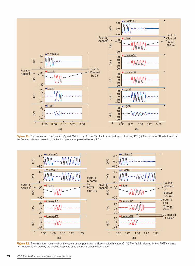
Figure 12. The simulation results when the synchronous generator is disconnected in case A2. (a) The fault is cleared by the POTT scheme. (b) The fault is isolated by the backup loop PDs once the POTT scheme has failed.
Fault IsApplied
v_vista-C
i_fault
i_grid
i_gen
4.0
–4.0
–30
2010
–10–20
2010
–10–20
0
0
2.90 3.00 3.10 3.20 3.30
Fault IsApplied
Fault IsClearedby C3
Fault IsClearedby C1
and C2
30
0.0(kV
)(k
A)
v_vista-C
i_fault
i_relay-C1
i_relay-C2
i_grid
i_gen
4.0
–4.0
–30
20100
0
–10–20
2010
–10–20
30
0.0
(kV
)(k
A)
(kA
)(k
A)
0
2010
–10–20
(kA
)0
2010
–10–20
(kA
)
(kA
)(k
A)
x
(a)
2.90 3.00 3.10 3.20 3.30x
(b)
Figure 11. The simulation results when P 4=SG MW in case A1. (a) The fault is cleared by the load-way PD. (b) The load-way PD failed to clear the fault, which was cleared by the backup protection provided by loop PDs.

IEEE Electr i f icat ion Magazine / MARCH 2014 77
loop 1 (see figure 2). figure 10 shows the instantaneous simulation results for the faulted phase. Here, v_vista-C is the voltage at Vista c, and i_fault, i_relay-C1 and i_relay-C2 are the fault current and relay c1 and relay c2 currents. in figure 10(a), the fault is cleared by the load-way Pd installed at Vista c. in this figure, the fault current of the load-way of Vista c is about 13 kA (rms), which triggers the load-way relay to clear the fault in less than 0.1 s. this time includes the time-oc delay and operating times of the relay and breaker. in figure 10(b), it is assumed that the load-way Pd has failed to clear the fault and the fault is cleared by the backup protection provid-ed by the two loop Pds at Vista c. in this figure, the fault clearing time is about 0.16 s, which is the total operating time of the primary and backup protections. figure 10(b) shows the current for the two loop Pds (c1 and c2). both scenarios result in building outages at Vista c;
however, the duration of the fault is much shorter when the fault is cleared by the load-way Pd.
figure 11 shows the results when the same fault has occurred at t = 3 s and the synchronous generator sup-plied 4 MW of the campus load according to the tertiary control sig-nal. the synchronous generator will also contribute to the fault current. Here, i_grid and i_gen are the cur-rents of the utility grid and the syn-chronous generator. figure 11(a) and (b) shows the scenarios in which the faults are cleared by load-way Pd and the backup loop Pds. in these figures, the utility grid contributes about 12 kA (rms), and the synchro-nous generator contributes 3 kA (rms) to the total fault current.
A2: Loop Faultthis case shows how the Pott scheme and its backup protection
Fault IsApplied
v_vista-C
v_vista-D
i_fault
i_relay-C1
i_relay-D2
i_grid
4.0
–4.0
0.0
30
0
–30
20100
–10–20
2.90 3.00 3.10 3.20 3.30
Fault IsApplied
Fault IsClearedbyPOTT(D2-C1)
Fault IsIsolatedby Backup(D2-C2)
Fault Is FedThroughVista C
D2 Tripped;C1 Failed
(kV
)
4.0
–4.0
0.0(kV
)(k
A)
(kA
)
20100
–10–20
(kA
)
20100
–10–20
(kA
)
i_gen20100
–10–20
(kA
)
x
(a)
v_vista-C
v_vista-D
i_fault
i_relay-C1
i_relay-D2
i_grid
4.0
–4.0
30
–30
20100
–10–20
2.90 3.00 3.10 3.20 3.30
(kV
)
4.0
–4.0
(kV
)(k
A)
(kA
)
20100
–10–20
(kA
)
20100
–10–20
(kA
)
i_gen20100
–10–20
(kA
)
x
(b)
Figure 13. The simulation results when P 4=SG MW in case A2. (a) The fault is cleared by the POTT scheme. (b) The fault is isolated by the backup loop PDs once the POTT scheme has failed.
Differential protection schemes are based on coupled differential directional relays that can accurately locate and isolate faults without affecting other components in distribution systems.

IEEE Electr i f icat ion Magazine / MARCH 201478
Fault IsApplied
Fault IsApplied
Fault IsClearedbyPOTT(D2-C1)
Fault IsIsolatedby Backup(D2-C2)
Fault Is FedThroughVista C
D2 Tripped;C1 Failed
v_vista-C
v_vista-D
i_fault
i_relay-C1
i_relay-D2
4.0
–4.0
0.0
10.05.00.0
–5.0–10.0
10.05.00.0
–5.0–10.0
10.05.00.0
–5.0–10.0
10.05.00.0
–5.0–10.0
10.05.00.0
0.0
0.0
–5.0–10.0
10.05.00.0
–5.0–10.0
10.05.00.0
–5.0–10.0
10.05.00.0
–5.0–10.0
2.90 3.00 3.10 3.20 3.30
(kV
)
4.0
–4.0
0.0
(kV
)(k
A)
(kA
)(k
A)
(kA
)
(kV
)(k
V)
(kA
)(k
A)
(kA
)(k
A)
i_gen
x x
(a)
v_vista-C
v_vista-D
i_fault
i_relay-C1
i_relay-D2
4.0
–4.0
2.90 3.00 3.10 3.20 3.30
4.0
–4.0
i_gen
(b)
Figure 15. The simulation results in case B2. (a) The fault is cleared by the POTT scheme. (b) The fault is isolated by the backup loop PDs once the POTT scheme has failed.
Fault IsApplied
v_vista-C
i_fault
4.0
–4.0
10.05.0
–5.0–10.0
0.0
0.0
Fault IsApplied
Fault IsClearedby C3
Fault IsClearedby C1and C2
(kV
)(k
A)
i_gen10.05.0
–5.0–10.0
0.0(kA
)
2.90 3.00 3.10 3.20 3.30x
(a)
v_vista-C
i_fault
i_relay-C1
i_relay-C2
4.0
–4.0
0.0
–10.0
2.90 3.00 3.10 3.20 3.30(k
V)
10.05.0
–5.00.0
–10.0
10.05.0
–5.00.0
–10.0
10.05.0
–5.00.0
–10.0
10.05.0
–5.00.0
(kA
)(k
A)
(kA
)(k
A)
i_gen
x
(b)
Figure 14. The simulation results in case B1. (a) The fault is cleared by the load-way PD. (b) The load-way PD failed to clear the fault, which is cleared by the backup protection provided by loop PDs.

IEEE Electr i f icat ion Magazine / MARCH 2014 79
scheme clear a loop fault in grid-connected mode. Here, we assume that the iit microgrid is connected to the utili-ty through the ns and that the synchronous generator is disconnected according to the tertiary control signal. A single-phase to ground fault occurs at t = 1 s in the loop section between Vista c and Vista d (see figure 2). figure 12(a) shows that the fault is cleared by the Pott scheme of coupled Pds within this section. since the fault location is close to the middle of the loop, both d2 and c1 detect about 7 kA (rms) fault current, so the fault is cleared in fewer than 0.1 s without any interruption to the electricity supply of the campus buildings. figure 12(b) shows that once the Pott scheme fails, the back protection scheme isolates the fault. in this figure, d2 has operated success-fully; however, c1 has failed and its backup Pd (c2) has been triggered to clear the fault. in figure 12(b), only one side of the loop (Vista c) supplies the fault current between t = 1.09 s and t = 1.17 s; therefore, during this period, the current flowing through relay d2 is reduced to zero while the current in relay c1 is increased, and the total fault current is reduced from 14 kA (rms) to 12 kA (rms). At 1.17 s, the fault is isolated by d2 and c2, and there is an outage in the building connected to the Vista c. in figure 13, we assume the same fault occurs at t = 3 s with the synchronous generator supplying 4 MW of campus load according to the tertiary control sig-nal. in this case, the synchronous generator will also contribute to the fault current. figure 13(a) and (b) shows the fault being cleared by the Pott scheme and its backup protec-tion, respectively. in these figures, the utility grid contributes about 12 kA (rms) and the synchronous generator contributes 3 kA (rms) to the total fault current.
Case B: Protection in Island ModeHere, the island mode protection is discussed. in this case, since the fault current level is reduced, the Mc sends signals to the load-way and loop Pds to change their relay settings to island mode.
B1: Load-Way Faultthis case shows how the protection scheme clears a load-way fault in island mode. A single-phase to ground fault occurs at t = 3 s on the load-way at Vista c in loop 1 (see figure 2), and the fault current is mainly provided by synchronous generator. in figure 14(a), the fault is cleared by the load-way Pd installed at Vista c. the fault current on the load-way of Vista c is about 3.2 kA (rms) as shown in this figure, and the load-way relay clears the fault in less than 0.1 s. this time delay includes the instantaneous/definite time delay of relay and the
breaker operating time. in figure 14(b), it is assumed that the load-way Pd has failed to clear the fault and the fault is cleared by the backup protection provided by the two loop Pds at Vista c. in this figure, the fault is cleared by the backup protection after about 0.16 s, which is the total operating time of the primary and backup protections. both scenarios result in building outages connected to Vista c. compared to case A1, the
fault current in figure 14 is signifi-cantly reduced in the island mode.
B2: Loop Faultthis case shows how the Pott and its backup protection schemes clear a loop fault in the island mode. A single-phase to ground fault occurs at t = 3 s on the loop section between Vista c and Vista d (see figure 2), and the fault current is mainly provided by the synchronous generator. in figure 15(a), the fault is cleared by the Pott scheme of coupled Pds (c1 and d2) in this loop section. since the fault location is close to the middle of the loop, both d2 and c1 detected about 2 kA (rms) fault current and the fault is cleared in fewer than
0.1 s without any supply interruption to the campus build-ings. figure 15(b) shows the case in which the fault is isolated by the backup loop Pds once the Pott scheme has failed. in this figure, breaker d2 successfully operated while c1 failed. the backup breaker at c2 is triggered to isolate the fault about 0.18 s after the fault is applied. As shown in figure 15(b), between 3.09 s and 3.18 s, only one side of the loop (Vista c) still supplies the fault current, so during this period, the current passing through relay d2 reduces to zero while the current passes through c1 increases, and the total fault current is reduced from about 4 kA (rms) to 3.1 kA (rms). in figure 15(b), there is an outage in the loads connected to Vista c as it is isolated from the loop. compared to case A2, the fault current is significantly reduced in island mode.
Figure 16. The simulation result in case C (weak-infeed loop fault).
Fault IsApplied
LowCurrent
ThroughLoop
PD A1
Fault IsIsolatedbyFeedersA and B
Feeder ATripped
Feeder BTripped
i_fault
i_feederA
i_feederB
30
30
30
–30
–30
–30x
0.80 1.20 1.60 2.00 2.40
(kA
)(k
A)
(kA
)
The difference between fault currents in grid-connected and island modes would necessitate adaptive protection schemes in microgrids.
IEEE Electr i f icat ion Magazine / MARCH 201480
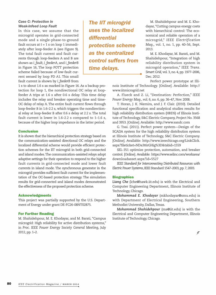
Case C: Protection in Weak-Infeed Loop Faultin this case, we assume that the microgrid operates in grid-connected mode and a single-phase-to-ground fault occurs at t = 1 s on loop 1 immedi-ately after loop-feeder A (see figure 9). the total fault current and fault cur-rents through loop-feeders A and b are shown as i_fault, i_feederA, and i_feederB in figure 16, the loop Pott protection scheme failed because of low-fault cur-rent sensed by loop Pd A1. this small fault current is shown by i_feederB from 1 s to about 1.6 s as marked in figure 16. As a backup pro-tection for loop 1, the nondirectional oc relay at loop-feeder A trips at 1.6 s after 0.6 s delay. this time delay includes the relay and breaker operating time and time-oc delay of relay A. the entire fault current flows through loop-feeder b in 1.6–2.2 s, which triggers the nondirection-al relay at loop-feeder b after 0.6 s delay at 2.2 s. the total fault current is lower in 1.6–2.2 s compared to 1–1.6 s, because of the higher loop impedance in the latter period.
Conclusionit is shown that the hierarchical protection strategy based on the communication-assisted directional oc relays and the localized differential scheme would provide efficient protec-tion schemes for the iit microgrid in both grid-connected and island modes. the communication-assisted relays adopt adaptive settings for their operation to respond to the higher fault currents in grid-connected mode and lower fault currents in island mode. the synchronous generator in the microgrid provides sufficient fault current for the implemen-tation of the oc-based protection strategy. the simulation results for grid-connected and island modes demonstrated the effectiveness of the proposed protection scheme.
Acknowledgmentsthis project was partially supported by the u.s. depart-ment of energy under grant de-fc26-08nt02875.
For Further ReadingM. shahidehpour, M. e. Khodayar, and M. barati, “campus microgrid: High reliability for active distribution systems,” in Proc. IEEE Power Energy Society General Meeting, July 2012, pp. 1–2.
M. shahidehpour and M. e. Kho-dayar, “cutting campus energy costs with hierarchical control: the eco-nomical and reliable operation of a microgrid,” IEEE Electrification Mag., vol. 1, no. 1, pp. 40–56, sept. 2013.
M. e. Khodayar, M. barati, and M. shahidehpour, “integration of high reliability distribution system in microgrid operation,” IEEE Trans. Smart Grid, vol. 3, no. 4, pp. 1977–2006, dec. 2012.
Perfect power prototype at illi-nois institute of technology. [online]. Available: http://www.iitmicrogrid.net
A. flueck and Z. Li, “destination: Perfection,” IEEE Power Energy Mag., vol. 6, no. 6, pp. 36–47, nov. 2008.
t. Horan, J. K. niemira, and J. f. clair. (2010). detailed functional specification and analytical studies results for high reliability distribution system (Hrds) of illinois insti-tute of technology, s&c electric company, Project no. 3568 and 3953. [online]. Available: http://www.sandc.com
g. tsai. (2011). Perfect power system—design of the scAdA system for the high reliability distribution system at illinois institute of technology, s&c electric company. [online]. Available: http://www.ieeechicago.org/Linkclick.aspx?fileticket=nda3t6rgHig%3d&tabid=1559
seL-351 optimize protection, automation, and breaker control. [online]. Available: https://www.selinc.com/workarea/ downloadasset.aspx?id=5527
IEEE Standard for Interconnecting Distributed Resources with Electric Power Systems, ieee standard 1547–2003, pp. 7, 2003.
Biographies Liang Che ([email protected]) is with the electrical and computer engineering department, illinois institute of technology, chicago.
Mohammad E. Khodayar ([email protected]) is with department of electrical engineering, southern Methodist university, dallas, texas.
Mohammad Shahidehpour ([email protected]) is with the electrical and computer engineering department, illinois institute of technology, chicago.
The IIT microgrid uses the localized differential protection scheme as the centralized control suffers from time delays.