
Energy Management and Voltage Control in Microgrids Using ...
22
Citation: Al Sumarmad, K.A.; Sulaiman, N.; Wahab, N.I.A.; Hizam, H. Energy Management and Voltage Control in Microgrids Using Artificial Neural Networks, PID, and Fuzzy Logic Controllers. Energies 2022, 15, 303. https://doi.org/10.3390/ en15010303 Academic Editors: Victor Becerra and Ahmed Rachid Received: 23 November 2021 Accepted: 22 December 2021 Published: 3 January 2022 Publisher’s Note: MDPI stays neutral with regard to jurisdictional claims in published maps and institutional affil- iations. Copyright: © 2022 by the authors. Licensee MDPI, Basel, Switzerland. This article is an open access article distributed under the terms and conditions of the Creative Commons Attribution (CC BY) license (https:// creativecommons.org/licenses/by/ 4.0/). energies Article Energy Management and Voltage Control in Microgrids Using Artificial Neural Networks, PID, and Fuzzy Logic Controllers Khaizaran Abdulhussein Al Sumarmad *, Nasri Sulaiman *, Noor Izzri Abdul Wahab and Hashim Hizam Department of Electrical and Electronic Engineering, Faculty of Engineering, University Putra Malaysia, Serdang 43400, Malaysia; [email protected] (N.I.A.W.); [email protected] (H.H.) * Correspondence: [email protected] (K.A.A.S.); [email protected] (N.S.) Abstract: Microgrids, comprising distributed generation, energy storage systems, and loads, have recently piqued users’ interest as a potentially viable renewable energy solution for combating climate change. According to the upstream electricity grid conditions, microgrid can operate in grid-connected and islanded modes. Energy storage systems play a critical role in maintaining the frequency and voltage stability of an islanded microgrid. As a result, several energy management systems techniques have been proposed. This paper introduces a microgrid system, an overview of local control in a microgrid, and an efficient EMS for effective microgrid operations using three smart controllers for optimal microgrid stability. We designed a microgrid consisting of renewable sources, Li-ion batteries, the main grid as a backup system, and AC/DC loads. The proposed system control was based on supplying loads as efficiently as possible using renewable energy sources and monitoring the battery’s state of charge. The simulation results using MATLAB Simulink demonstrate the performance of the three proposed microgrid stability strategies (PID, artificial neural network, and fuzzy logic). The comparison results confirmed the viability and effectiveness of the proposed technique for energy management in a microgrid which is based on fuzzy logic controllers. Keywords: microgrid; PID; fuzzy logic; artificial neural network; distributed generation; energy storage system 1. Introduction Smart grid principles that are fundamentally new will be required in future power systems. Flexible microgrids (MGs) that can operate in both grid-connected and island modes are necessary in this regard. The primary goal of a microgrid system is to meet load demand by prioritizing the energy produced by renewable sources over energy supplied by auxiliary sources, such as those powered by diesel [1]. The savings realized by such systems must at least offset the investment required by renewable generators and other system components. Renewable energy resources (RESs) are used; therefore, the microgrid (MG) is not only cost-effective, adaptable, and stable, but it also provides environmental benefits as compared to traditional utility networks [2]. Microgrids also encourage the participation of small power sources in the market, which can be aggregated to provide the power needed to achieve the distributed generators’ (DG) target goals. Due to the various power sources that might be mixed, studying microgrid safety and stability is difficult [3]. The load demand, which impacts the microgrid structure at the design stage, is usually taken into account when evaluating microgrid stability and control [4]. The high awareness of distributed generation (DG) in power grids poses a challenge to the power system’s process and stability. To ensure microgrids’ stability and safety, only microgrid (MG) construction and control approaches for DG are required [5]. Much research has been conducted in recent years on MGs’ sizing, control, energy management, and operation. An energy management system is required in a microgrid Energies 2022, 15, 303. https://doi.org/10.3390/en15010303 https://www.mdpi.com/journal/energies
-
Upload
khangminh22 -
Category
Documents
-
view
2 -
download
0
Transcript of Energy Management and Voltage Control in Microgrids Using ...

�����������������
Citation: Al Sumarmad, K.A.;
Sulaiman, N.; Wahab, N.I.A.; Hizam,
H. Energy Management and Voltage
Control in Microgrids Using Artificial
Neural Networks, PID, and Fuzzy
Logic Controllers. Energies 2022, 15,
303. https://doi.org/10.3390/
en15010303
Academic Editors: Victor Becerra and
Ahmed Rachid
Received: 23 November 2021
Accepted: 22 December 2021
Published: 3 January 2022
Publisher’s Note: MDPI stays neutral
with regard to jurisdictional claims in
published maps and institutional affil-
iations.
Copyright: © 2022 by the authors.
Licensee MDPI, Basel, Switzerland.
This article is an open access article
distributed under the terms and
conditions of the Creative Commons
Attribution (CC BY) license (https://
creativecommons.org/licenses/by/
4.0/).
energies
Article
Energy Management and Voltage Control in Microgrids UsingArtificial Neural Networks, PID, and Fuzzy Logic ControllersKhaizaran Abdulhussein Al Sumarmad *, Nasri Sulaiman *, Noor Izzri Abdul Wahab and Hashim Hizam
Department of Electrical and Electronic Engineering, Faculty of Engineering, University Putra Malaysia,Serdang 43400, Malaysia; [email protected] (N.I.A.W.); [email protected] (H.H.)* Correspondence: [email protected] (K.A.A.S.); [email protected] (N.S.)
Abstract: Microgrids, comprising distributed generation, energy storage systems, and loads, haverecently piqued users’ interest as a potentially viable renewable energy solution for combatingclimate change. According to the upstream electricity grid conditions, microgrid can operate ingrid-connected and islanded modes. Energy storage systems play a critical role in maintaining thefrequency and voltage stability of an islanded microgrid. As a result, several energy managementsystems techniques have been proposed. This paper introduces a microgrid system, an overviewof local control in a microgrid, and an efficient EMS for effective microgrid operations using threesmart controllers for optimal microgrid stability. We designed a microgrid consisting of renewablesources, Li-ion batteries, the main grid as a backup system, and AC/DC loads. The proposed systemcontrol was based on supplying loads as efficiently as possible using renewable energy sources andmonitoring the battery’s state of charge. The simulation results using MATLAB Simulink demonstratethe performance of the three proposed microgrid stability strategies (PID, artificial neural network,and fuzzy logic). The comparison results confirmed the viability and effectiveness of the proposedtechnique for energy management in a microgrid which is based on fuzzy logic controllers.
Keywords: microgrid; PID; fuzzy logic; artificial neural network; distributed generation; energystorage system
1. Introduction
Smart grid principles that are fundamentally new will be required in future powersystems. Flexible microgrids (MGs) that can operate in both grid-connected and islandmodes are necessary in this regard. The primary goal of a microgrid system is to meet loaddemand by prioritizing the energy produced by renewable sources over energy suppliedby auxiliary sources, such as those powered by diesel [1]. The savings realized by suchsystems must at least offset the investment required by renewable generators and othersystem components. Renewable energy resources (RESs) are used; therefore, the microgrid(MG) is not only cost-effective, adaptable, and stable, but it also provides environmentalbenefits as compared to traditional utility networks [2].
Microgrids also encourage the participation of small power sources in the market,which can be aggregated to provide the power needed to achieve the distributed generators’(DG) target goals. Due to the various power sources that might be mixed, studyingmicrogrid safety and stability is difficult [3]. The load demand, which impacts the microgridstructure at the design stage, is usually taken into account when evaluating microgridstability and control [4]. The high awareness of distributed generation (DG) in powergrids poses a challenge to the power system’s process and stability. To ensure microgrids’stability and safety, only microgrid (MG) construction and control approaches for DG arerequired [5].
Much research has been conducted in recent years on MGs’ sizing, control, energymanagement, and operation. An energy management system is required in a microgrid
Energies 2022, 15, 303. https://doi.org/10.3390/en15010303 https://www.mdpi.com/journal/energies

Energies 2022, 15, 303 2 of 22
system to govern the flow of power and energy between sources and loads and givecustomers high-quality, safe, sustainable, and environmentally friendly energy [6]. Thispaper will introduce the microgrids concept, microgrid control architecture, and localcontrol in microgrids.
A microgrid (MG) is a low- or medium-voltage hybrid electrical system which com-prises several energy sources based primarily on renewable resources to offer high-qualityelectricity to small consumers in rural areas that are separated or isolated [7]. MGs canfunction in two operational modes, depending on the technical and economic conditions:in a connected mode linked to the main grid through a common coupling point (CCP) orin an islanded mode [8]. Currently, the concept and definition of microgrids are chang-ing to provide customers with sustainable energy choices in terms of renewable energyintegration, grid reliability, flexibility, and economy.
MGs can increase overall system efficiency, improve power supply quality, and provideusers with control over their electrical supply [9]. A microgrid is an energy system thatincludes management intelligence and consists of several components.
A typical microgrid control hierarchy is depicted in Figure 1. In general, an intelligentmicrogrid EMS must manage and coordinate a mix of DGs, energy storage systems (ESSs),and loads to supply high-quality, reliable, sustainable, and environmentally friendly energyat a reasonable cost.
Energies 2022, 15, x FOR PEER REVIEW 2 of 22
microgrids’ stability and safety, only microgrid (MG) construction and control approaches
for DG are required [5].
Much research has been conducted in recent years on MGs’ sizing, control, energy
management, and operation. An energy management system is required in a microgrid
system to govern the flow of power and energy between sources and loads and give
customers high-quality, safe, sustainable, and environmentally friendly energy [6]. This
paper will introduce the microgrids concept, microgrid control architecture, and local
control in microgrids.
A microgrid (MG) is a low- or medium-voltage hybrid electrical system which
comprises several energy sources based primarily on renewable resources to offer high-
quality electricity to small consumers in rural areas that are separated or isolated [7]. MGs
can function in two operational modes, depending on the technical and economic
conditions: in a connected mode linked to the main grid through a common coupling
point (CCP) or in an islanded mode [8]. Currently, the concept and definition of
microgrids are changing to provide customers with sustainable energy choices in terms
of renewable energy integration, grid reliability, flexibility, and economy.
MGs can increase overall system efficiency, improve power supply quality, and
provide users with control over their electrical supply [9]. A microgrid is an energy system
that includes management intelligence and consists of several components.
A typical microgrid control hierarchy is depicted in Figure 1. In general, an intelligent
microgrid EMS must manage and coordinate a mix of DGs, energy storage systems (ESSs),
and loads to supply high-quality, reliable, sustainable, and environmentally friendly
energy at a reasonable cost.
Figure 1. Microgrid structure.
A microgrid can run autonomously in island mode and can also be connected to the
main grid.
Grid-connected mode: When the MG’s total production exceeds its consumption, it
is connected to the main grid to meet its energy needs and can provide or receive power
from it. An MG is generally related to a low- or medium-voltage (MV) distribution system
through the point of standard coupling (PCC), which is termed the point of
interconnection [10]. ESSs in MGs can manage voltage and frequency variations within
acceptable limits to ensure the MG system’s reliability. In grid-connected mode, MGs use
ESSs to store backup production and peak load operation during extended grid outages,
Figure 1. Microgrid structure.
A microgrid can run autonomously in island mode and can also be connected to themain grid.
Grid-connected mode: When the MG’s total production exceeds its consumption, itis connected to the main grid to meet its energy needs and can provide or receive powerfrom it. An MG is generally related to a low- or medium-voltage (MV) distribution systemthrough the point of standard coupling (PCC), which is termed the point of interconnec-tion [10]. ESSs in MGs can manage voltage and frequency variations within acceptablelimits to ensure the MG system’s reliability. In grid-connected mode, MGs use ESSs to storebackup production and peak load operation during extended grid outages, as well as gridstability assistance to control voltage and frequency limits and energy demand.
Islanded mode: The microgrid is isolated from the power distribution grid in islandedmode, providing a consistent power supply to loads from DG generation and energystorage. The safety and stability of the microgrid system improve with the incorporationof an ESS, and the system can moderate power changes in renewable energy output. In

Energies 2022, 15, 303 3 of 22
instances of faults in the main grid, the microgrid will operate independently to retain itsintegrity in islanded mode with the support of the DG and ESS [11].
The major goal is to conserve the system’s voltage and frequency under rigorouscontrol. Following islanding, the MG’s reconnection is synchronized automatically usingfrequency variations between the islanded mode and the main grid. The microgrid controlsystem ensures that all the control functionalities are achieved. Its role is to ensure equaland precise power-sharing in the system, and voltage and frequency should be regulated.EMS functions can be carried out in a centralized or decentralized manner.
The centralized control: All data measurements from the power grid are relayed to acentral controller (CC), which decides the control actions for the entire system to maintaina balance between all microgrid entities. A local controller (LC) is used by each entity tocollect data and communicate with the central controller (CC) (Figure 2a). Furthermore,new communication and processing technologies and communication protocols, such asoptical fiber, are being used. A CC has the ability to monitor, evaluate, and make choices inreal time [12].
Energies 2022, 15, x FOR PEER REVIEW 3 of 22
as well as grid stability assistance to control voltage and frequency limits and energy
demand.
Islanded mode: The microgrid is isolated from the power distribution grid in
islanded mode, providing a consistent power supply to loads from DG generation and
energy storage. The safety and stability of the microgrid system improve with the
incorporation of an ESS, and the system can moderate power changes in renewable energy
output. In instances of faults in the main grid, the microgrid will operate independently
to retain its integrity in islanded mode with the support of the DG and ESS [11].
The major goal is to conserve the system’s voltage and frequency under rigorous
control. Following islanding, the MG’s reconnection is synchronized automatically using
frequency variations between the islanded mode and the main grid. The microgrid control
system ensures that all the control functionalities are achieved. Its role is to ensure equal
and precise power-sharing in the system, and voltage and frequency should be regulated.
EMS functions can be carried out in a centralized or decentralized manner.
The centralized control: All data measurements from the power grid are relayed to a
central controller (CC), which decides the control actions for the entire system to maintain
a balance between all microgrid entities. A local controller (LC) is used by each entity to
collect data and communicate with the central controller (CC) (Figure 2a). Furthermore,
new communication and processing technologies and communication protocols, such as
optical fiber, are being used. A CC has the ability to monitor, evaluate, and make choices
in real time [12].
Due to the complexity of the power system, this strategy is unreliable, and it
necessitates a high-bandwidth communication connection for rapid data transfer. When
power sources are dispersed over a vast region with significant distances between them,
this form of control is impossible because if the control operator fails to ensure control for
any reason, the entire system may fail to function.
Decentralized control: In contrast to centralized control, the decentralized method
considers each entity autonomously and uses local control. In this technique, a leader
controls each entity separately based on local data and communication with other local
controls for global control. This control method has the advantage of boosting the
microgrid’s reliability by making all units independent from each another and responsible
for their voltage and frequency management. Limited local agents are required in
decentralized control techniques, and control choices are only assigned based on local
measures (Figure 2b). The intelligence of local controllers, which can be employed to
execute directives from higher levels or make their judgments, determines the extent of
decentralization [13].
Figure 2. (a) Centralized and (b) decentralized control structure. Figure 2. (a) Centralized and (b) decentralized control structure.
Due to the complexity of the power system, this strategy is unreliable, and it necessi-tates a high-bandwidth communication connection for rapid data transfer. When powersources are dispersed over a vast region with significant distances between them, this formof control is impossible because if the control operator fails to ensure control for any reason,the entire system may fail to function.
Decentralized control: In contrast to centralized control, the decentralized method con-siders each entity autonomously and uses local control. In this technique, a leader controlseach entity separately based on local data and communication with other local controls forglobal control. This control method has the advantage of boosting the microgrid’s reliabil-ity by making all units independent from each another and responsible for their voltageand frequency management. Limited local agents are required in decentralized controltechniques, and control choices are only assigned based on local measures (Figure 2b). Theintelligence of local controllers, which can be employed to execute directives from higherlevels or make their judgments, determines the extent of decentralization [13].
Traditional control systems have been widely employed in MGs to maintain voltageand frequency stability and regulation, particularly during grid connection. In general,power generation information is used to modulate MG voltage and frequency in a hierarchi-cal controls system. Tertiary, secondary, and primary control groups make up hierarchicalcontrol. Due to the necessity to maintain real-time frequency and voltage stability duringdisturbances, primary control levels are regarded as the most difficult [13]. In MG applica-tions, the next section shows how to use local control for energy management in a hybridmicrogrid to keep voltage and frequency within acceptable limits.

Energies 2022, 15, 303 4 of 22
Several study approaches in the literature have presented energy management advance-ments in microgrids for energy management, control, and monitoring. For example, in [14], areliable communication protocol and Internet of Things (IoT) technologies are presented formicrogrid power flow control. The authors in [15] offer a computational intelligence-basedenergy management system (EMS) in MGs. A multiagent system is used to reduce thecost of energy consumed in an intelligent building by incorporating several energy-savingtechniques, as well as two energy-saving incentive and instruction strategies, as well asnumerous student engagement behaviors, based on a graphic novel tool for studying MGenergy flows in real time or throughout the full dataset being analyzed in [16]. The authorsof [17] illustrate several fundamental features of an MG control framework, including:
• Voltage and frequency profiles are regulated in both islanded and networkedoperation modes;
• Grid synchronization with the main grid;• MG’s entire energy management system is optimized;• As much as feasible, cut the MG’s operational costs.
In [18], the authors developed an integrated resource planning approach for dis-tributed hybrid microgrids that takes into account virtual–inertia support (VIS) anddemand–response support (DRS) systems. With the availability of solar/wind/bioenergyresources, three unequally distributed sustainable-energy-based hybrid microgrids areinitially envisioned.
The administration and scheduling of a number of microgrids (MGs) in virtual powerplants are managed and scheduled using an artificial neural network (ANN) as an in-telligent controller in this study (VPP). The ANN-based backtracking search algorithm(ANN-BBSA) and the ANN-based binary practical swarm optimization (ANN-BPSO)method are two ANN-based scheduling control approaches proposed in [19].
According to the above discussion, this paper proposes advanced microgrid modeling,a decentralized approach for smart energy management, and efficient voltage control usingsmart techniques based on intelligent algorithms. The proposed EMS is extended to analyzethe autonomous MG voltage control using a powerful control based on artificial intelligence.
The rest of this paper is laid out as follows. In Section 2, an overview of local control inmicrogrids is described. Section 3 gives the microgrid modeling. The energy managementsystem proposed is presented in Section 4. Section 5 offers the design system of theproposed controllers for a microgrid. The simulation result and discussion are introducedin Section 6. Finally, this paper is concluded in Section 6.
2. Overview of Local Control in Microgrids
Microgrids’ control purposes are to maintain stable system operation, regulate lowvoltage, and equalize load sharing among distributed generators per unit under steady-state conditions (DGs). Local control is a good energy management technique in a hybridmicrogrid. In low-voltage microgrid applications, however, nominal voltage referenceoffsets and unequal connecting cable resistances will require a trade-off between voltageregulation and load sharing.
Classically, various control methods have been used to control microgrids, such asPI/PID linear control, fuzzy logic, and artificial neural network control. This sectionprovides an overview of the control techniques used for energy management, voltage, andfrequency control in the microgrid used in this paper.
2.1. Proportional–Integral–Derivative (PID) Technique
PID control is a broad feedback control technique commonly used in the automaticcontrollers of industrial control systems. PID controllers are the most widely used methodsfor engineering application controls, and they transform the error signal into an inputsignal using a proportional factor (P), integrative action (I), and differential action (D) [20].The error signal, which reflects the PID controller’s input, is obtained by comparing themeasured output signal with its desired reference. The error signal is processed by the PID

Energies 2022, 15, 303 5 of 22
controllers in order to reduce it. The authors of [21] propose employing a PI controller ina hybrid vehicle to recover regenerative braking energy while charging the battery andkeeping the electric vehicle’s voltage bus constant. A comparison of the responses of PIand PID-controlled bidirectional DC–DC converter systems is also included in [22]. ThePID controller must automatically regulate power disruption or load variation effects, asshown in the example in [23]. The parameters in this controller are chosen via trial anderror or other strategies, such as those proposed by Ziegler and Nicholas. PID/PI is strong,safe, and provides near-optimal control system performance with the suitable tuning ofgains. However, for nonlinear and complicated systems, the PI/PID tuning strategies havelimited ability to tune the PID additions appropriately. The PID performance is heavilyreliant on the appropriate circumstances of the PID parameters inside this framework [24].
2.2. Neural Networks for Microgrid Control
An artificial neural network (ANN) control technique has recently been employedfor microgrid control—notably, voltage and frequency regulation—in a variety of applica-tions [25], including the management of power equipment such as inverters and bi-directioninverters in AC microgrids. ANN controllers have proven to display a rapid responsetime and a high level of stability and reliability. It has the potential to increase an ACmicrogrid’s frequency and voltage stability, as well as power quality, and to ensure rapidtransitions between modes [26]. However, no study has been carried out using ANNs tocontrol DC/DC converters or to use ANNs to govern DC microgrids. In [27], a preliminaryinvestigation was published on creating an ANN-based DC/DC converter control systemand combining it with a droop mechanism to regulate a freestanding DC microgrid. Thewind speed was estimated in real time using a back-propagation ANN in [28]. In [29], adiscrete-time NN controller for controlling the DC distribution system is proposed. Anupdated Elman neural network (ANN) and a radial Basis function network (RBFN) arepresented as MPPT controllers for various types of RES in [30].
To address the uncertainties of DC–DC converters (DDCs), Kazemlou and Mehraeen [31]present a decentralized NN controller, which integrates the scattered sources of a DC grid andstabilizes the output voltage in the event of a disturbance. Low-inertia distribution systems aregiven special attention, such as solar panels connected to the DC bus via a buck converter. Tomaintain stability, the suggested controller uses an adaptive approach to change the duty cycle;input and output voltages and currents must be measurable, but communication between theconverters is not required. Two NNs at the front-end converter in [32] manage the DC-busvoltage as well as the active and reactive power flows.
2.3. Fuzzy Logic in Power Systems
Fuzzy control is based on fuzzy logic, which resembles human reasoning and naturallanguage significantly more closely than classic analytical systems [33].
Fuzzy logic is now used in practically every industry, science, and power grid. Fre-quency regulations in microgrids is one such application. The fundamental goal of fre-quency management in microgrid systems is to maintain the balance between output andconsumption. Due to their durability and reliability, fuzzy controllers effectively address awide range of control challenges. Fuzzy logic is similar to human logic and outperformsPID controllers. In nonlinear systems, fuzzy control is more adaptive than typical PIDcontrollers and has a shorter settling time [34].
In addition, fuzzy logic control (FLC) has been used to create an energy managementsystem (EMS). In addition to EMSs for stand-alone microgrids [35,36] proposes EMSs fora DC microgrid based on a fuzzy logic controller. The proposed FLC prioritizes sellingadditional electricity generated by renewable energy sources (RES) while keeping thebattery state of charge (SOC) above 50% to extend battery life. This heuristic knowledgeadvises using fuzzy logic control to create the EMS for the circumstance under examina-tion. This technique effortlessly combines the user’s experience rather than employing a

Energies 2022, 15, 303 6 of 22
mathematical model of the system. Furthermore, an improved EMS design based on FLCwas shown [37].
The advantages and disadvantages of various control strategies are given in Table 1 [38].
Table 1. Brief comparison of control approaches.
Techniques Advantages Disadvantages
PID Controller
• Easy to implement;• Realization does not
necessitate systemdynamics;
• Only three parameters tooptimize.
• Cannot ensure theresilience of PIDclosed-loop systems;
• Cannot removesteady-state errors forsinusoidal signals;
• Not adaptable to loadvariations.
• Artificial neuralnetworks Controller
• In online or offlineapplications, thetechnique can control,optimize, and identifythe system’s parameters;
• Use nonlinear datatechniques to solvechallenges in large-scalesystems in MGs;
• Self-learning andprediction are used tosolve the system’sstability and faulttolerance.
• The model’s structure iscomplicated;
• Difficult to determine thebest network structurewhen adding or raisingunits from the MGtopology (black boxes);
• Difficult to determine thebest network structurewhen adding or raisingunits from the MGtopology;
• Only possible if thesystem structure isstable.
• Fuzzy logic Controller
• Better voltage andfrequency management,as well as power sharingbetween many MGs.
• A high-qualityprocessing unit isrequired;
• Error methods are usedfor the participationfunction;
• The procedure istime-consuming.
3. Microgrid Modeling
The studied autonomous hybrid microgrid comprises two renewable energy sources(photovoltaic and wind), battery energy storage as backup source, and loads. Microgridscan be connected to the main grid via a common coupling point (CCP).
3.1. Photovoltaic System
As shown in Figure 3, the photovoltaic system consisted of a photovoltaic panel, aboost converter, and a maximum power point tracking (MPPT) controller.

Energies 2022, 15, 303 7 of 22
Energies 2022, 15, x FOR PEER REVIEW 7 of 22
3.1. Photovoltaic System
As shown in Figure 3, the photovoltaic system consisted of a photovoltaic panel, a
boost converter, and a maximum power point tracking (MPPT) controller.
A photovoltaic cell is an electronic component that generates electricity by exposing
it to sunlight. The cell can be used on its own or in a photovoltaic panel with other solar
cells. There are several PV cell models available, each with its own level of complexity and
precision. Photovoltaic cells can be modeled by the equivalent electrical circuit given in
Figure 4.
Figure 3. Photovoltaic system.
Figure 4. Equivalent electrical diagram of a photovoltaic cell.
The following equation models the current of the PV cell:
�� = ��� − �� ������� � �� �
�� − 1� −��� + �� �
���
(1)
�� =�� � � �
� (2)
VT: The thermal voltage;
Ns: Cells connected in series;
n: The diode ideality constant;
q: Charge of the electron;
k: The Boltzmann constant;
T: The temperature of the p–n junction;
Iph: The photo-current;
I0: Reverse saturation currents of the diode.
As a reference module, we used a MATLAB/Simulink-implemented PV model (Sun
Power SPR-250NX-BLK-D). The 250 W module was chosen to make the calculation easier.
The properties of this PV model are listed in Table 2.
Figure 3. Photovoltaic system.
A photovoltaic cell is an electronic component that generates electricity by exposingit to sunlight. The cell can be used on its own or in a photovoltaic panel with other solarcells. There are several PV cell models available, each with its own level of complexityand precision. Photovoltaic cells can be modeled by the equivalent electrical circuit givenin Figure 4.
Energies 2022, 15, x FOR PEER REVIEW 7 of 22
3.1. Photovoltaic System
As shown in Figure 3, the photovoltaic system consisted of a photovoltaic panel, a
boost converter, and a maximum power point tracking (MPPT) controller.
A photovoltaic cell is an electronic component that generates electricity by exposing
it to sunlight. The cell can be used on its own or in a photovoltaic panel with other solar
cells. There are several PV cell models available, each with its own level of complexity and
precision. Photovoltaic cells can be modeled by the equivalent electrical circuit given in
Figure 4.
Figure 3. Photovoltaic system.
Figure 4. Equivalent electrical diagram of a photovoltaic cell.
The following equation models the current of the PV cell:
�� = ��� − �� ������� � �� �
�� − 1� −��� + �� �
���
(1)
�� =�� � � �
� (2)
VT: The thermal voltage;
Ns: Cells connected in series;
n: The diode ideality constant;
q: Charge of the electron;
k: The Boltzmann constant;
T: The temperature of the p–n junction;
Iph: The photo-current;
I0: Reverse saturation currents of the diode.
As a reference module, we used a MATLAB/Simulink-implemented PV model (Sun
Power SPR-250NX-BLK-D). The 250 W module was chosen to make the calculation easier.
The properties of this PV model are listed in Table 2.
Figure 4. Equivalent electrical diagram of a photovoltaic cell.
The following equation models the current of the PV cell:
Id = Iph − I0
(exp
Vpv+Rs IVT − 1
)−
Vpv + Rs IRsh
(1)
VT =Ns n k T
q(2)
VT: The thermal voltage;Ns: Cells connected in series;n: The diode ideality constant;q: Charge of the electron;k: The Boltzmann constant;T: The temperature of the p–n junction;Iph: The photo-current;I0: Reverse saturation currents of the diode.As a reference module, we used a MATLAB/Simulink-implemented PV model (Sun
Power SPR-250NX-BLK-D). The 250 W module was chosen to make the calculation easier.The properties of this PV model are listed in Table 2.

Energies 2022, 15, 303 8 of 22
Table 2. Characteristics of (Sun Power SPR-250NX-BLK-D) PV model.
Parameters Values
Maximum power 250 W
Maximum power voltage 42.8 V
Maximum power current 5.84 A
Open circuit voltage 50.93 V
Current court-circuit 6.2 A
Cellule numbers 72
Temperature coefficient of open-circuit voltage −0.29103%/◦C
Temperature Coefficient of current court-circuit 0.013306%/◦C
Shunt resistance 448.6949 ohms
Series resistance 0.37759
A static converter (DC/DC power converter) is used as an adapter between PVgenerators and the load to collect the maximum power produced and transfer it to theload. The boost converter is controlled by an MPPT (maximum power point tracking)controller to offer maximum power efficiency at all times. They perturb and observe(P&O) [39] method is used in this paper. To acquire the highest power delivered by thePV, this program employs an iterative strategy based on an algorithmic process, as shownin Figure 5.
Energies 2022, 15, x FOR PEER REVIEW 8 of 22
Table 2. Characteristics of (Sun Power SPR-250NX-BLK-D) PV model.
Parameters Values
Maximum power 250 W
Maximum power voltage 42.8 V
Maximum power current 5.84 A
Open circuit voltage 50.93 V
Current court-circuit 6.2 A
Cellule numbers 72
Temperature coefficient of open-circuit voltage −0.29103%/°C
Temperature Coefficient of current court-circuit 0.013306%/°C
Shunt resistance 448.6949 ohms
Series resistance 0.37759
A static converter (DC/DC power converter) is used as an adapter between PV
generators and the load to collect the maximum power produced and transfer it to the
load. The boost converter is controlled by an MPPT (maximum power point tracking)
controller to offer maximum power efficiency at all times. They perturb and observe
(P&O) [39] method is used in this paper. To acquire the highest power delivered by the
PV, this program employs an iterative strategy based on an algorithmic process, as shown
in Figure 5.
Figure 5. Flowchart of MPPT algorithm.
3.2. Wind Turbine System
Wind energy systems (WESs) are the most readily available and promising source of
electrical energy. The kinetic energy of the wind is used to spin turbines, which provide
mechanical energy. Generators transform mechanical energy into electrical energy. As a
result, wind energy is generated in a linear connection with wind speed. The MPPT
control unit works based on following the maximum power point for each wind speed
[40]. A wind turbine’s optimum power is distinctively nonlinear and bell-shaped. The
system looks for the maximum power for each wind speed, analogously to looking for the
best rotational speed. The power is plotted as a function of the rotating speed of the
turbine. There is only one setting for each wind speed which enables the maximum power
to be obtained.
Figure 5. Flowchart of MPPT algorithm.
3.2. Wind Turbine System
Wind energy systems (WESs) are the most readily available and promising source ofelectrical energy. The kinetic energy of the wind is used to spin turbines, which providemechanical energy. Generators transform mechanical energy into electrical energy. As aresult, wind energy is generated in a linear connection with wind speed. The MPPT controlunit works based on following the maximum power point for each wind speed [40]. A windturbine’s optimum power is distinctively nonlinear and bell-shaped. The system looks forthe maximum power for each wind speed, analogously to looking for the best rotational
Energies 2022, 15, 303 9 of 22
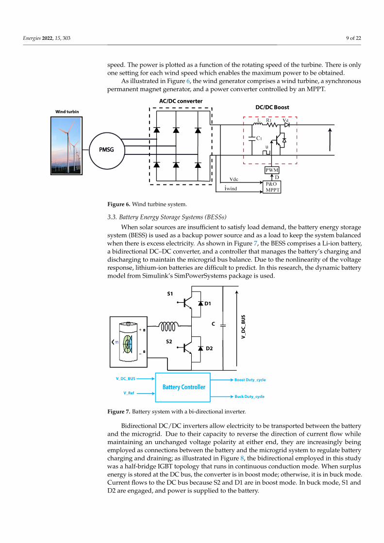
speed. The power is plotted as a function of the rotating speed of the turbine. There is onlyone setting for each wind speed which enables the maximum power to be obtained.
As illustrated in Figure 6, the wind generator comprises a wind turbine, a synchronouspermanent magnet generator, and a power converter controlled by an MPPT.
Energies 2022, 15, x FOR PEER REVIEW 9 of 22
As illustrated in Figure 6, the wind generator comprises a wind turbine, a
synchronous permanent magnet generator, and a power converter controlled by an
MPPT.
Figure 6. Wind turbine system.
3.3. Battery Energy Storage Systems (BESSs)
When solar sources are insufficient to satisfy load demand, the battery energy storage
system (BESS) is used as a backup power source and as a load to keep the system balanced
when there is excess electricity. As shown in Figure 7, the BESS comprises a Li-ion battery,
a bidirectional DC–DC converter, and a controller that manages the battery’s charging
and discharging to maintain the microgrid bus balance. Due to the nonlinearity of the
voltage response, lithium-ion batteries are difficult to predict. In this research, the
dynamic battery model from Simulink’s SimPowerSystems package is used.
Bidirectional DC/DC inverters allow electricity to be transported between the battery
and the microgrid. Due to their capacity to reverse the direction of current flow while
maintaining an unchanged voltage polarity at either end, they are increasingly being
employed as connections between the battery and the microgrid system to regulate
battery charging and draining; as illustrated in Figure 8, the bidirectional employed in this
study was a half-bridge IGBT topology that runs in continuous conduction mode. When
surplus energy is stored at the DC bus, the converter is in boost mode; otherwise, it is in
buck mode. Current flows to the DC bus because S2 and D1 are in boost mode. In buck
mode, S1 and D2 are engaged, and power is supplied to the battery.
Figure 7. Battery system with a bi-directional inverter.
Figure 6. Wind turbine system.
3.3. Battery Energy Storage Systems (BESSs)
When solar sources are insufficient to satisfy load demand, the battery energy storagesystem (BESS) is used as a backup power source and as a load to keep the system balancedwhen there is excess electricity. As shown in Figure 7, the BESS comprises a Li-ion battery,a bidirectional DC–DC converter, and a controller that manages the battery’s charging anddischarging to maintain the microgrid bus balance. Due to the nonlinearity of the voltageresponse, lithium-ion batteries are difficult to predict. In this research, the dynamic batterymodel from Simulink’s SimPowerSystems package is used.
Energies 2022, 15, x FOR PEER REVIEW 9 of 22
As illustrated in Figure 6, the wind generator comprises a wind turbine, a
synchronous permanent magnet generator, and a power converter controlled by an
MPPT.
Figure 6. Wind turbine system.
3.3. Battery Energy Storage Systems (BESSs)
When solar sources are insufficient to satisfy load demand, the battery energy storage
system (BESS) is used as a backup power source and as a load to keep the system balanced
when there is excess electricity. As shown in Figure 7, the BESS comprises a Li-ion battery,
a bidirectional DC–DC converter, and a controller that manages the battery’s charging
and discharging to maintain the microgrid bus balance. Due to the nonlinearity of the
voltage response, lithium-ion batteries are difficult to predict. In this research, the
dynamic battery model from Simulink’s SimPowerSystems package is used.
Bidirectional DC/DC inverters allow electricity to be transported between the battery
and the microgrid. Due to their capacity to reverse the direction of current flow while
maintaining an unchanged voltage polarity at either end, they are increasingly being
employed as connections between the battery and the microgrid system to regulate
battery charging and draining; as illustrated in Figure 8, the bidirectional employed in this
study was a half-bridge IGBT topology that runs in continuous conduction mode. When
surplus energy is stored at the DC bus, the converter is in boost mode; otherwise, it is in
buck mode. Current flows to the DC bus because S2 and D1 are in boost mode. In buck
mode, S1 and D2 are engaged, and power is supplied to the battery.
Figure 7. Battery system with a bi-directional inverter. Figure 7. Battery system with a bi-directional inverter.
Bidirectional DC/DC inverters allow electricity to be transported between the batteryand the microgrid. Due to their capacity to reverse the direction of current flow whilemaintaining an unchanged voltage polarity at either end, they are increasingly beingemployed as connections between the battery and the microgrid system to regulate batterycharging and draining; as illustrated in Figure 8, the bidirectional employed in this studywas a half-bridge IGBT topology that runs in continuous conduction mode. When surplusenergy is stored at the DC bus, the converter is in boost mode; otherwise, it is in buck mode.Current flows to the DC bus because S2 and D1 are in boost mode. In buck mode, S1 andD2 are engaged, and power is supplied to the battery.
Energies 2022, 15, 303 10 of 22Energies 2022, 15, x FOR PEER REVIEW 10 of 22
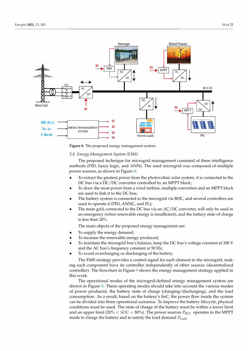
Figure 8. The proposed energy management system.
3.4. Energy Management System (EMS)
The proposed technique for microgrid management consisted of three intelligence
methods (PID, fuzzy logic, and ANN). The used microgrid was composed of multiple
power sources, as shown in Figure 8:
To extract the greatest power from the photovoltaic solar system, it is connected to
the DC bus via a DC/DC converter controlled by an MPPT block;
To draw the most power from a wind turbine, multiple converters and an MPPT
block are used to link it to the DC bus;
The battery system is connected to the microgrid via BDC, and several controllers are
used to operate it (PID, ANNC, and FL);
The main grid, connected to the DC bus via an AC/DC converter, will only be used
in an emergency (when renewable energy is insufficient), and the battery state of
charge is less than 20%.
The main objects of the proposed energy management are:
• To supply the energy demand;
• To increase the renewable energy produced;
• To maintain the microgrid bus’s balance, keep the DC bus’s voltage constant at 300
V and the AC bus’s frequency constant at 50 Hz;
• To avoid overcharging or discharging of the battery.
The EMS strategy provides a control signal for each element in the microgrid, making
each component have its controller independently of other sources (decentralized
controller). The flowchart in Figure 9 shows the energy management strategy applied in
this work.
The operational modes of the microgrid-defined energy management system are
shown in Figure 9. These operating modes should take into account the various modes of
power produced, the battery state of charge (charging/discharging), and the load
consumption. As a result, based on the battery’s SoC, the power flow inside the system
can be divided into three operational scenarios. To improve the battery lifecycle, physical
conditions must be used. The state of charge of the battery must be within a lower limit
Figure 8. The proposed energy management system.
3.4. Energy Management System (EMS)
The proposed technique for microgrid management consisted of three intelligencemethods (PID, fuzzy logic, and ANN). The used microgrid was composed of multiplepower sources, as shown in Figure 8:
• To extract the greatest power from the photovoltaic solar system, it is connected to theDC bus via a DC/DC converter controlled by an MPPT block;
• To draw the most power from a wind turbine, multiple converters and an MPPT blockare used to link it to the DC bus;
• The battery system is connected to the microgrid via BDC, and several controllers areused to operate it (PID, ANNC, and FL);
• The main grid, connected to the DC bus via an AC/DC converter, will only be used inan emergency (when renewable energy is insufficient), and the battery state of chargeis less than 20%.
The main objects of the proposed energy management are:
• To supply the energy demand;• To increase the renewable energy produced;• To maintain the microgrid bus’s balance, keep the DC bus’s voltage constant at 300 V
and the AC bus’s frequency constant at 50 Hz;• To avoid overcharging or discharging of the battery.
The EMS strategy provides a control signal for each element in the microgrid, mak-ing each component have its controller independently of other sources (decentralizedcontroller). The flowchart in Figure 9 shows the energy management strategy applied inthis work.
The operational modes of the microgrid-defined energy management system areshown in Figure 9. These operating modes should take into account the various modesof power produced, the battery state of charge (charging/discharging), and the loadconsumption. As a result, based on the battery’s SoC, the power flow inside the systemcan be divided into three operational scenarios. To improve the battery lifecycle, physicalconditions must be used. The state of charge of the battery must be within a lower limitand an upper limit (20% < SOC < 80%). The power sources PRES operates in the MPPTmode to charge the battery and to satisfy the load demand PLoad.

Energies 2022, 15, 303 11 of 22
Energies 2022, 15, x FOR PEER REVIEW 11 of 22
and an upper limit (20% < ��� < 80%). The power sources ���� operates in the MPPT
mode to charge the battery and to satisfy the load demand ����� .
In charging mode (���� > ����� ), when the power produced from PV and wind
sources is more than the load demand, the battery absorbs the excess power in the DC bus
to regulate the voltage and frequency of the microgrid.
In the event that the power source module is unable to meet the load requirement
(���� < �����), the battery can assist in meeting the need.
Figure 9. Flowchart of the energy management strategy.
4. Control Design for the Microgrid
This section presents the design of the controller systems developed in this paper for
energy management and voltage control.
4.1. PID Controller Design
The most often utilized method for engineering application control is PID controllers.
They use a proportional factor (P) and integrative action to turn error signals into input
signals (I). When comparing the measured output signal with their intended references to
obtain the error signal, which is the PID controller’s input, The PID controllers decrease
the error signal.
The difference between the measured voltage (V-DC-Bus) and the desired voltage
(V-reference) is amplified by the controller to produce the Error signal (e).
Figure 9. Flowchart of the energy management strategy.
In charging mode (PRES > PLoad), when the power produced from PV and windsources is more than the load demand, the battery absorbs the excess power in the DC busto regulate the voltage and frequency of the microgrid.
In the event that the power source module is unable to meet the load requirement(PRES < PLoad), the battery can assist in meeting the need.
4. Control Design for the Microgrid
This section presents the design of the controller systems developed in this paper forenergy management and voltage control.
4.1. PID Controller Design
The most often utilized method for engineering application control is PID controllers.They use a proportional factor (P) and integrative action to turn error signals into inputsignals (I). When comparing the measured output signal with their intended references toobtain the error signal, which is the PID controller’s input, The PID controllers decrease theerror signal.
The difference between the measured voltage (V-DC-Bus) and the desired voltage(V-reference) is amplified by the controller to produce the Error signal (e).
The bidirectional converter keeps the voltage fixed at 300 V and balances betweenload production and consumption. In this study, we performed a simulation. The controlstrategy used in this system is shown in Figure 10. The bidirectional converter was voltage-controlled; therefore, the DC_BUS voltage was measured and compared with the reference

Energies 2022, 15, 303 12 of 22
voltage. The difference between these voltage values was processed in PID blocks andgenerated the duty cycle of each direction. The suggested battery charger algorithmgenerated the duty cycle value for controlling the system converter using a PWM signalbased on the voltage and battery state of charge measured at the DC bus.
Energies 2022, 15, x FOR PEER REVIEW 12 of 22
The bidirectional converter keeps the voltage fixed at 300 V and balances between
load production and consumption. In this study, we performed a simulation. The control
strategy used in this system is shown in Figure 10. The bidirectional converter was
voltage-controlled; therefore, the DC_BUS voltage was measured and compared with the
reference voltage. The difference between these voltage values was processed in PID
blocks and generated the duty cycle of each direction. The suggested battery charger
algorithm generated the duty cycle value for controlling the system converter using a
PWM signal based on the voltage and battery state of charge measured at the DC bus.
The controller output altered the PWM signal to reduce inaccuracy by changing the
power-sharing via a DC–DC bidirectional converter between the battery and microgrid.
The reference model (300 V) was chosen to provide a response which is optimal and
similar to the reference input.
Figure 10. Schema of the PID controller implementation.
The output of the PID controller can be expressed as [40]:
�(�) = �� �(�) +��
� �(�) + ��. �. �(�) (3)
T The transfer function can be written as follows:
�(�) =�(�)
�(�)= �� +
��
� + ��. � (4)
where �(�) = |���� − ���|
The propositional gain (Kp) will minimize the rising time, but not the steady-state
error. Although the integral gain (KI) eliminates the steady-state error, it may exacerbate
the sudden response. The derivative gain (Kd) will improve the transient responsiveness
by boosting system stability, lowering overshoot, and minimizing overshoot. S is the
Laplace operator.
4.2. Fuzzy Logic Controller Design
In a variety of difficult fields, fuzzy logic control (FLC) is widely used. FLC is
regarded as one of the most intelligently shot solutions to distributed power optimization
issues. FLC functions have been studied in depth to provide more capability in dealing
with expert system issues. The development of a fuzzy logic controller for integration into
the microgrid was based on the Fuzzy Logic toolbox from MATLAB/Simulink.
The partial matching capacity of fuzzy rule reasoning is a key characteristic, because
it allows inference from fuzzy rules even when their conditions are only partially met.
Figure 11 shows a block diagram of the fuzzy logic controller [41,42].
Figure 10. Schema of the PID controller implementation.
The controller output altered the PWM signal to reduce inaccuracy by changing thepower-sharing via a DC–DC bidirectional converter between the battery and microgrid.The reference model (300 V) was chosen to provide a response which is optimal and similarto the reference input.
The output of the PID controller can be expressed as [40]:
u(s) = Kp e(s) +KIS
e(s) + KD.S.e(s) (3)
T The transfer function can be written as follows:
H(s) =u(s)e(s)
= Kp +KIS
+ KD.S (4)
where e(s) =∣∣∣Vre f − VDC
∣∣∣.The propositional gain (Kp) will minimize the rising time, but not the steady-state
error. Although the integral gain (KI) eliminates the steady-state error, it may exacerbatethe sudden response. The derivative gain (KD) will improve the transient responsivenessby boosting system stability, lowering overshoot, and minimizing overshoot. S is theLaplace operator.
4.2. Fuzzy Logic Controller Design
In a variety of difficult fields, fuzzy logic control (FLC) is widely used. FLC is regardedas one of the most intelligently shot solutions to distributed power optimization issues.FLC functions have been studied in depth to provide more capability in dealing withexpert system issues. The development of a fuzzy logic controller for integration into themicrogrid was based on the Fuzzy Logic toolbox from MATLAB/Simulink.
The partial matching capacity of fuzzy rule reasoning is a key characteristic, becauseit allows inference from fuzzy rules even when their conditions are only partially met.Figure 11 shows a block diagram of the fuzzy logic controller [41,42].
Energies 2022, 15, x FOR PEER REVIEW 13 of 22
Figure 11. Block diagram of the fuzzy control system.
The FLC is made up of three parts: fuzzification, fuzzy inference system, and
defuzzification. A fuzzy set is used to express a fuzzy variable which is defined by a
membership function in general. Fuzzification is the process of converting a crisp input
into a linguistic variable. Fuzzification is a task that requires expertise. Membership
functions are triangle-shaped or trapezoidal-shaped. The inference is the following block,
which is a rule-based task based on expert knowledge. Defuzzification returns a crisp
value to the linguistic variable.
In this paper, the membership functions for input error used for microgrid control
are presented in Figure 12.
Figure 12. Error signal membership functions.
We have considered three Linguistic variables (Negative, Positive, Right) for the
Input ‘Error’, and for the output Control, we have considered three Linguistic variables
(Up, down, and no change), as shown in Figure 13.
The fuzzy controller generated an appropriate switching pattern for the charging and
draining of the battery. When the DC bus voltage and a reference voltage were compared,
Figure 11. Block diagram of the fuzzy control system.

Energies 2022, 15, 303 13 of 22
The FLC is made up of three parts: fuzzification, fuzzy inference system, and defuzzi-fication. A fuzzy set is used to express a fuzzy variable which is defined by a membershipfunction in general. Fuzzification is the process of converting a crisp input into a linguis-tic variable. Fuzzification is a task that requires expertise. Membership functions aretriangle-shaped or trapezoidal-shaped. The inference is the following block, which is arule-based task based on expert knowledge. Defuzzification returns a crisp value to thelinguistic variable.
In this paper, the membership functions for input error used for microgrid control arepresented in Figure 12.
Energies 2022, 15, x FOR PEER REVIEW 13 of 22
Figure 11. Block diagram of the fuzzy control system.
The FLC is made up of three parts: fuzzification, fuzzy inference system, and
defuzzification. A fuzzy set is used to express a fuzzy variable which is defined by a
membership function in general. Fuzzification is the process of converting a crisp input
into a linguistic variable. Fuzzification is a task that requires expertise. Membership
functions are triangle-shaped or trapezoidal-shaped. The inference is the following block,
which is a rule-based task based on expert knowledge. Defuzzification returns a crisp
value to the linguistic variable.
In this paper, the membership functions for input error used for microgrid control
are presented in Figure 12.
Figure 12. Error signal membership functions.
We have considered three Linguistic variables (Negative, Positive, Right) for the
Input ‘Error’, and for the output Control, we have considered three Linguistic variables
(Up, down, and no change), as shown in Figure 13.
The fuzzy controller generated an appropriate switching pattern for the charging and
draining of the battery. When the DC bus voltage and a reference voltage were compared,
Figure 12. Error signal membership functions.
We have considered three Linguistic variables (Negative, Positive, Right) for the Input‘Error’, and for the output Control, we have considered three Linguistic variables (Up,down, and no change), as shown in Figure 13.
The fuzzy controller generated an appropriate switching pattern for the charging anddraining of the battery. When the DC bus voltage and a reference voltage were compared,the fuzzy logic controller received four inputs. As seen in Figure 13, it supplies the dutycycle for the PWM block to deliver the signal to the buck/boost converter.

Energies 2022, 15, 303 14 of 22
Energies 2022, 15, x FOR PEER REVIEW 14 of 22
the fuzzy logic controller received four inputs. As seen in Figure 13, it supplies the duty
cycle for the PWM block to deliver the signal to the buck/boost converter.
Figure 13. Membership function for output.
4.3. ANN Controller Design
With considerable success, the artificial neural network controller (ANNC) has been
employed to control engineering applications. This sort of control’s primary goal is to
linearize nonlinear dynamics. Two neural networks make up the NARMA L2 controllers:
the first is the NARMA model, which represents broad discrete-time nonlinear systems in
system identification; the second is for the control design, as shown in Figure 14.
Figure 14. NARMA-L2 Model plant.
Figure 13. Membership function for output.
4.3. ANN Controller Design
With considerable success, the artificial neural network controller (ANNC) has beenemployed to control engineering applications. This sort of control’s primary goal is tolinearize nonlinear dynamics. Two neural networks make up the NARMA L2 controllers:the first is the NARMA model, which represents broad discrete-time nonlinear systems insystem identification; the second is for the control design, as shown in Figure 14.
Energies 2022, 15, x FOR PEER REVIEW 14 of 22
the fuzzy logic controller received four inputs. As seen in Figure 13, it supplies the duty
cycle for the PWM block to deliver the signal to the buck/boost converter.
Figure 13. Membership function for output.
4.3. ANN Controller Design
With considerable success, the artificial neural network controller (ANNC) has been
employed to control engineering applications. This sort of control’s primary goal is to
linearize nonlinear dynamics. Two neural networks make up the NARMA L2 controllers:
the first is the NARMA model, which represents broad discrete-time nonlinear systems in
system identification; the second is for the control design, as shown in Figure 14.
Figure 14. NARMA-L2 Model plant. Figure 14. NARMA-L2 Model plant.

Energies 2022, 15, 303 15 of 22
Therefore, using the NARMA-L2 model, we can obtain the following controller:
u(k + 1) =Y(k + d)− f [y(k), . . . , y(k − n + 1), u(k), . . . , u(k − n + 1)]
g[y(k), . . . , y(k − n + 1), u(k), . . . , u(k − n + 1)](5)
This paper utilized the ANC to manage the bidirectional DC–DC converter by produc-ing the duty cycle for the PWM to keep the DC bus voltage constant at the reference voltagevalue. As a result, the reference, DC bus voltage, and duty cycle values on the outputwere the ANC’s inputs. To create a database for ANNC, numerous tests were conducted.The approach measured the DC bus and duty cycle voltages while simulating variousirradiation and load power values.
5. Simulation and Results
The hybrid microgrid system (Figure 15) is composed of hybrid DC and AC sources.To extract the most power from each renewable source, each power source is connected tothe microgrid’s DC bus via a power converter. The solar cell type is Sunpower SPR 250NX-BLK with 49 panels in series and 11 in parallel to provide a full power of 65 KW. Thewind turbine type is PMSG and provides a maximum power of 20 KW. The battery type isLi-ion, capacity = 280 Ah, and voltage V = 200 V. The load demands in DC Bus is P = 10 KWand V = 300 V. The loads required in AC Bus are P = 20 KW between t = 0 s and 0.5 s andP = 60 KW between t = 0.5 and t = 1 s.
Energies 2022, 15, x FOR PEER REVIEW 15 of 22
Therefore, using the NARMA-L2 model, we can obtain the following controller:
�(� + 1) =�(� + �) − �[�(�), … , �(� − � + 1), �(�), … , �(� − � + 1)]
�[�(�), … , �(� − � + 1), �(�), … , �(� − � + 1)] (5)
This paper utilized the ANC to manage the bidirectional DC–DC converter by
producing the duty cycle for the PWM to keep the DC bus voltage constant at the reference
voltage value. As a result, the reference, DC bus voltage, and duty cycle values on the
output were the ANC’s inputs. To create a database for ANNC, numerous tests were
conducted. The approach measured the DC bus and duty cycle voltages while simulating
various irradiation and load power values.
5. Simulation and Results
The hybrid microgrid system (Figure 15) is composed of hybrid DC and AC sources.
To extract the most power from each renewable source, each power source is connected
to the microgrid’s DC bus via a power converter. The solar cell type is Sunpower SPR 250
NX-BLK with 49 panels in series and 11 in parallel to provide a full power of 65 KW. The
wind turbine type is PMSG and provides a maximum power of 20 KW. The battery type
is Li-ion, capacity = 280 Ah, and voltage V = 200 V. The load demands in DC Bus is P = 10
KW and V = 300 V. The loads required in AC Bus are P = 20 KW between t = 0 s and 0.5 s
and P = 60 KW between t = 0.5 and t = 1 s.
Figure 15. Simulink file of the proposed EMS with multiple controllers.
The simulation runs for one second with a 1 × 10⁻⁵ sampling rate to compare the
reaction of the proposed energy management method with each controller in the
microgrid balance during changes in weather conditions. The results of interface
monitoring show how each piece reacts to the numerous adjustments.
Figures 16 and 17 show the variation of the produced power from PV panels and
wind turbines within the proposed meteorological scenario.
At the beginning of the simulation between t = 0 s and t = 0.3 s, the sum of the power
produced from the renewable sources was less than 30 KW (DC and AC loads demanded).
The maximum PV power produced was about 10 KW, and the wind power was about 1
KW. This means that the battery discharged to provide energy for the microgrid to
maintain the power balance and provide power for both loads because the battery’s state
of charge (SOC) was limited to 20% < SOC < 80%. The decline in the state of charge curve
and the battery power of 35 KW, as illustrated in Figures 18 and 19, indicates that the
battery provided energy in the range of 34 KW. Therefore, the power needs problem in
the DC bus was solved. In addition, between t = 0.3 s and t = 0.5 s, the solar eyes increased
Figure 15. Simulink file of the proposed EMS with multiple controllers.
The simulation runs for one second with a 1 × 10⁻⁵ sampling rate to compare thereaction of the proposed energy management method with each controller in the microgridbalance during changes in weather conditions. The results of interface monitoring showhow each piece reacts to the numerous adjustments.
Figures 16 and 17 show the variation of the produced power from PV panels and windturbines within the proposed meteorological scenario.

Energies 2022, 15, 303 16 of 22
Energies 2022, 15, x FOR PEER REVIEW 16 of 22
more than 35 KW, and the wind power increased to 10 KW, which means that there was
an energy surplus and the system became unbalanced. As we already described, the
battery is the main element for the system balance. Due to the battery state of charge in its
safe zone, the battery stored the surplus to balance the power production and
consumption.
Figure 16. The power produced from PV panels (W).
Figure 17. The power produced from wind turbines (W).
Figure 16. The power produced from PV panels (W).
Energies 2022, 15, x FOR PEER REVIEW 16 of 22
more than 35 KW, and the wind power increased to 10 KW, which means that there was
an energy surplus and the system became unbalanced. As we already described, the
battery is the main element for the system balance. Due to the battery state of charge in its
safe zone, the battery stored the surplus to balance the power production and
consumption.
Figure 16. The power produced from PV panels (W).
Figure 17. The power produced from wind turbines (W). Figure 17. The power produced from wind turbines (W).
At the beginning of the simulation between t = 0 s and t = 0.3 s, the sum of the powerproduced from the renewable sources was less than 30 KW (DC and AC loads demanded).The maximum PV power produced was about 10 KW, and the wind power was about 1 KW.This means that the battery discharged to provide energy for the microgrid to maintain thepower balance and provide power for both loads because the battery’s state of charge (SOC)was limited to 20% < SOC < 80%. The decline in the state of charge curve and the batterypower of 35 KW, as illustrated in Figures 18 and 19, indicates that the battery providedenergy in the range of 34 KW. Therefore, the power needs problem in the DC bus wassolved. In addition, between t = 0.3 s and t = 0.5 s, the solar eyes increased more than35 KW, and the wind power increased to 10 KW, which means that there was an energysurplus and the system became unbalanced. As we already described, the battery is the

Energies 2022, 15, 303 17 of 22
main element for the system balance. Due to the battery state of charge in its safe zone, thebattery stored the surplus to balance the power production and consumption.
Energies 2022, 15, x FOR PEER REVIEW 17 of 22
Figure 18. Variation in the battery state of charge (%).
Figure 19. Variation in battery power (W).
At t = 0.5 s, the power demand of the AC bus increased to 70 KW. The solar power at
this time equaled its maximum value of 70 KW, and the wind turbine equaled 10 KW.
Therefore, the surplus of energy stored in the battery was reduced compared with the
previous interval, and the slope of charging decreased, as shown in Figures 17 and 18.
At t = 0.6, the irradiation value decreased again, decreasing the primary source (solar
system). At t = 0.8 s, the sum of renewable sources became less than the loads demanded,
which means that the battery will be discharged again to provide the surplus power of
the microgrid. Notably, the difference between produced and requested power increases,
which means that the power supplied by the battery increased linearly with this
difference.
Figure 18. Variation in the battery state of charge (%).
Energies 2022, 15, x FOR PEER REVIEW 17 of 22
Figure 18. Variation in the battery state of charge (%).
Figure 19. Variation in battery power (W).
At t = 0.5 s, the power demand of the AC bus increased to 70 KW. The solar power at
this time equaled its maximum value of 70 KW, and the wind turbine equaled 10 KW.
Therefore, the surplus of energy stored in the battery was reduced compared with the
previous interval, and the slope of charging decreased, as shown in Figures 17 and 18.
At t = 0.6, the irradiation value decreased again, decreasing the primary source (solar
system). At t = 0.8 s, the sum of renewable sources became less than the loads demanded,
which means that the battery will be discharged again to provide the surplus power of
the microgrid. Notably, the difference between produced and requested power increases,
which means that the power supplied by the battery increased linearly with this
difference.
Figure 19. Variation in battery power (W).
At t = 0.5 s, the power demand of the AC bus increased to 70 KW. The solar powerat this time equaled its maximum value of 70 KW, and the wind turbine equaled 10 KW.Therefore, the surplus of energy stored in the battery was reduced compared with theprevious interval, and the slope of charging decreased, as shown in Figures 17 and 18.
At t = 0.6, the irradiation value decreased again, decreasing the primary source (solarsystem). At t = 0.8 s, the sum of renewable sources became less than the loads demanded,which means that the battery will be discharged again to provide the surplus power ofthe microgrid. Notably, the difference between produced and requested power increases,which means that the power supplied by the battery increased linearly with this difference.
As stated at the outset, the goal of this study was to balance the amount of energyin microgrid systems while also regulating the voltage and frequency on the DC and AC

Energies 2022, 15, 303 18 of 22
buses. Figures 20 and 21 depict the measured values of power and voltage in the DC bus,respectively, whereas Figure 22 depicts the frequency variation of the AC bus.
Energies 2022, 15, x FOR PEER REVIEW 18 of 22
As stated at the outset, the goal of this study was to balance the amount of energy in
microgrid systems while also regulating the voltage and frequency on the DC and AC
buses. Figures 20 and 21 depict the measured values of power and voltage in the DC bus,
respectively, whereas Figure 22 depicts the frequency variation of the AC bus.
Figure 20. Measured voltage at the DC bus (V).
Figure 21. Measured power at the DC Bus (W).
Figure 20. Measured voltage at the DC bus (V).
Energies 2022, 15, x FOR PEER REVIEW 18 of 22
As stated at the outset, the goal of this study was to balance the amount of energy in microgrid systems while also regulating the voltage and frequency on the DC and AC buses. Figures 20 and 21 depict the measured values of power and voltage in the DC bus, respectively, whereas Figure 22 depicts the frequency variation of the AC bus.
Figure 20. Measured voltage at the DC bus (V).
Figure 21. Measured power at the DC Bus (W). Figure 21. Measured power at the DC Bus (W).
The power measured in the AC and DC bus shows that the DC load consumed 10 KW,and the AC load consumed 20 KW between t = 0 s and t = 0.5 s, and 60 KW betweent = 0.5 s to t = 1 s; the voltage of the DC bus was stable at 300 V, as already requested atthe beginning of the simulation. From Figures 19–21, we can conclude the considerableadvantages of artificial intelligence (ANN and FL) methods in stabilizing voltage andpower at the reference value.

Energies 2022, 15, 303 19 of 22Energies 2022, 15, x FOR PEER REVIEW 19 of 22
Figure 22. Measured power at the AC bus (W).
The power measured in the AC and DC bus shows that the DC load consumed 10
KW, and the AC load consumed 20 KW between t = 0 s and t = 0.5 s, and 60 KW between
t = 0.5 s to t = 1 s; the voltage of the DC bus was stable at 300 V, as already requested at the
beginning of the simulation. From Figures 19–21, we can conclude the considerable
advantages of artificial intelligence (ANN and FL) methods in stabilizing voltage and
power at the reference value.
Figure 23 shows that the frequency variation of the three methods in the limit merges
was ±0.02, except at the beginning of the simulation, which is called the transitory regime
and was not considered. The minimum variation in the frequency corresponded to the
fuzzy logic response. Therefore, we conclude the efficiency of fuzzy logic controllers in
the stability of microgrid voltage power and frequency from comparing the three
controllers. The simulation results explain the effectiveness and robustness of the
proposed EMS in the face of all changes in meteorological conditions and load demand.
Figure 23. Measured frequency at the AC bus (Hz).
Figure 22. Measured power at the AC bus (W).
Figure 23 shows that the frequency variation of the three methods in the limit mergeswas ±0.02, except at the beginning of the simulation, which is called the transitory regimeand was not considered. The minimum variation in the frequency corresponded to thefuzzy logic response. Therefore, we conclude the efficiency of fuzzy logic controllers in thestability of microgrid voltage power and frequency from comparing the three controllers.The simulation results explain the effectiveness and robustness of the proposed EMS in theface of all changes in meteorological conditions and load demand.
Energies 2022, 15, x FOR PEER REVIEW 19 of 22
Figure 22. Measured power at the AC bus (W).
The power measured in the AC and DC bus shows that the DC load consumed 10
KW, and the AC load consumed 20 KW between t = 0 s and t = 0.5 s, and 60 KW between
t = 0.5 s to t = 1 s; the voltage of the DC bus was stable at 300 V, as already requested at the
beginning of the simulation. From Figures 19–21, we can conclude the considerable
advantages of artificial intelligence (ANN and FL) methods in stabilizing voltage and
power at the reference value.
Figure 23 shows that the frequency variation of the three methods in the limit merges
was ±0.02, except at the beginning of the simulation, which is called the transitory regime
and was not considered. The minimum variation in the frequency corresponded to the
fuzzy logic response. Therefore, we conclude the efficiency of fuzzy logic controllers in
the stability of microgrid voltage power and frequency from comparing the three
controllers. The simulation results explain the effectiveness and robustness of the
proposed EMS in the face of all changes in meteorological conditions and load demand.
Figure 23. Measured frequency at the AC bus (Hz). Figure 23. Measured frequency at the AC bus (Hz).
6. Conclusions
For the MGs controlled by the various smart approaches in this study, the researchersdeveloped a novel distributed control architecture. The contribution of this study presentsthe design and development of three smart controllers’ methods for energy managementin the microgrid. The controllers are designed for application to hybrid microgrids withbattery energy system control to enhance the MG voltage and frequency under differentsystem load operations and different solar irradiation. The proposed methodologies’

Energies 2022, 15, 303 20 of 22
performance was evaluated, utilizing a variety of load dynamics in various scenariosdependent on metrology circumstances. The obtained results using the proposed controllersguarantee the safe operation and high stability of the microgrid. The simulation results alsoshowed that the fuzzy logic controller is better than the others (PID and ANN) in terms ofefficiency and precision. Future work related to this topic includes:
• Hardware implementation of the three methods (PID, ANN, and FL) to validate theperformance in experimental processes;
• The integration of energy optimization (electricity, price, and CO2 emissions) in globalmanagement of the energy management system.
Author Contributions: Conceptualization, K.A.A.S., N.S., N.I.A.W. and H.H.; methodology, K.A.A.S.,N.S., N.I.A.W. and H.H.; software, K.A.A.S., N.S., N.I.A.W. and H.H.; validation, N.S., N.I.A.W. andH.H.; formal analysis, K.A.A.S., N.S., N.I.A.W. and H.H.; investigation, K.A.A.S., N.S., N.I.A.W. andH.H.; resources, K.A.A.S., N.S., N.I.A.W. and H.H.; data curation, K.A.A.S.; writing—original draftpreparation, K.A.A.S.; writing—review and editing, K.A.A.S., N.S.; visualization, K.A.A.S., N.S.;supervision, N.S., N.I.A.W. and H.H.; project administration, K.A.A.S., N.S. and N.I.A.W. All authorshave read and agreed to the published version of the manuscript.
Funding: This research received no external funding.
Institutional Review Board Statement: Not applicable.
Informed Consent Statement: Not applicable.
Data Availability Statement: Not applicable.
Acknowledgments: This work supported by the University Putra Malaysia.
Conflicts of Interest: The authors declare no conflict of interest.
Abbreviations
ANN Artificial neural networkBESS Battery energy storage systemCCP Common coupling pointCC Central controllerDG Distributed generationESS Energy storage systemEMS Energy management systemFL Fuzzy logicLC Local controllerMG MicrogridMPPT Maximum power point trackingRES Renewable energy resourceRBFN Radial basis function networkPID Proportional-integral-derivativePV PhotovoltaicPWM Pulsewidth modulationSOC State of charge
References1. Molina, M.G. Energy storage and power electronics technologies: A strong combination to empower the transformation to the
smart grid. Proc. IEEE 2017, 105, 2191–2219. [CrossRef]2. Justo, J.J.; Mwasilu, F.; Lee, J.; Jung, J.W. AC-microgrids versus DC-microgrids with distributed energy resources: A review.
Renew. Sustain. Energy Rev. 2013, 24, 387–405. [CrossRef]3. Sen, S.; Kumar, V. Microgrid control: A comprehensive survey. Annu. Rev. Control 2018, 45, 118–151. [CrossRef]4. Wei, X.; Xiangning, X.; Pengwei, C. Overview of key microgrid technologies. Int. Trans. Electr. Energy Syst. 2018, 28, e2566.
[CrossRef]5. Yazdanian, M.; Mehrizi-Sani, A. Distributed control techniques in microgrids. IEEE Trans. Smart Grid 2014, 5, 2901–2909.
[CrossRef]

Energies 2022, 15, 303 21 of 22
6. Roslan, M.F.; Hannan, M.A.; Ker, P.J.; Uddin, M.N. Microgrid control methods toward achieving sustainable energy management.Appl. Energy 2019, 240, 583–607. [CrossRef]
7. Mahmoud, M.S.; Hussain, S.A.; Abido, M.A. Modeling and control of microgrid: An overview. J. Frankl. Inst. 2014, 351, 2822–2859.[CrossRef]
8. Lede, A.M.R.; Molina, M.G.; Martinez, M.; Mercado, P.E. Microgrid architectures for distributed generation: A brief review. InProceedings of the 2017 IEEE PES Innovative Smart Grid Technologies Conference-Latin America (ISGT Latin America), Quito,Ecuador, 20–22 September 2017; pp. 1–6.
9. Palizban, O.; Kauhaniemi, K.; Guerrero, J.M. Microgrids in active network management—Part II: System operation, power qualityand protection. Renew. Sustain. Energy Rev. 2014, 36, 440–451. [CrossRef]
10. Azeroual, M.; Lamhamdi, T.; El Moussaoui, H.; El Markhi, H. Simulation tools for a smart grid and energy management formicrogrid with wind power using multi-agent system. Wind. Eng. 2020, 44, 661–672. [CrossRef]
11. Mazidi, M.; Rezaei, N.; Ardakani, F.J.; Mohiti, M.; Guerrero, J.M. A hierarchical energy management system for islandedmulti-microgrid clusters considering frequency security constraints. Int. J. Electr. Power Energy Syst. 2020, 121, 106134. [CrossRef]
12. Tsikalakis, A.G.; Hatziargyriou, N.D. Centralized control for optimizing microgrids operation. In Proceedings of the 2011 IEEEPower and Energy Society General Meeting, Detroit, MI, USA, 24–29 July 2011; pp. 1–8.
13. Khorsandi, A.; Ashourloo, M.; Mokhtari, H. A decentralized control method for a low-voltage DC microgrid. IEEE Trans. EnergyConvers. 2014, 29, 793–801. [CrossRef]
14. Li, Y.; Sun, Z.; Han, L.; Mei, N. Fuzzy comprehensive evaluation method for energy management systems based on an Internet ofThings. IEEE Access 2017, 5, 21312–21322. [CrossRef]
15. Leonori, S.; Martino, A.; Mascioli, F.M.F.; Rizzi, A. Microgrid energy management systems design by computational intelligencetechniques. Appl. Energy 2020, 277, 115524. [CrossRef]
16. Ding, Z.; Hu, T.; Li, M.; Xu, X.; Zou, P.X. Agent-based model for simulating building energy management in student residences.Energy Build. 2019, 198, 11–27. [CrossRef]
17. Mobashsher, M.M.; Keypour, R.; Savaghebi, M. Distributed optimal voltage control in islanded microgrids. Int. Trans. Electr.Energy Syst. 2021, 31, e13045. [CrossRef]
18. Barik, A.K.; Das, D.C.; Latif, A.; Hussain, S.M.; Ustun, T.S. Optimal Voltage–Frequency Regulation in Distributed SustainableEnergy-Based Hybrid Microgrids with Integrated Resource Planning. Energies 2021, 14, 2735. [CrossRef]
19. Arfeen, Z.A.; Khairuddin, A.B.; Larik, R.M.; Saeed, M.S. Control of distributed generation systems for microgrid applications: Atechnological review. Int. Trans. Electr. Energy Syst. 2019, 29, e12072. [CrossRef]
20. Abdolrasol, M.G.M.; Hannan, M.A.; Hussain, S.M.; Ustun, T.S.; Sarker, M.R.; Ker, P.J. Energy Management Scheduling forMicrogrids in the Virtual Power Plant System Using Artificial Neural Networks. Energies 2021, 14, 6507. [CrossRef]
21. Kasimalla, V.K.; Velisala, V. A review on energy allocation of fuel cell/battery/ultracapacitor for hybrid electric vehicles. Int. J.Energy Res. 2018, 42, 4263–4283. [CrossRef]
22. Ramya, K.C.; Jegathesan, V. Comparison of pi and PID controlled bidirectional dc-dc converter systems. Int. J. Power Electron.Drive Syst. 2016, 7, 56. [CrossRef]
23. Chen, Z.; Yuan, X.; Ji, B.; Wang, P.; Tian, H. Design of a fractional order PID controller for hydraulic turbine regulating systemusing chaotic non-dominated sorting genetic algorithm II. Energy Convers. Manag. 2014, 84, 390–404. [CrossRef]
24. Wang, L.; Liu, J.; Yang, C.; Wu, D. A novel interval dynamic reliability computation approach for the risk evaluation of vibrationactive control systems based on PID controllers. Appl. Math. Model. 2021, 92, 422–446. [CrossRef]
25. Bakar, N.N.A.; Hassan, M.Y.; Sulaima, M.F.; Na’im Mohd Nasir, M.; Khamis, A. Microgrid and load shedding scheme duringislanded mode: A review. Renew. Sustain. Energy Rev. 2017, 71, 161–169. [CrossRef]
26. Boujoudar, Y.; Azeroual, M.; El Moussaoui, H.; Lamhamdi, T. Intelligent controller based energy management for stand-alonepower system using artificial neural network. Int. Trans. Electr. Energy Syst. 2020, 30, e12579. [CrossRef]
27. Albarakati, A.J.; Boujoudar, Y.; Azeroual, M.; Jabeur, R.; Aljarbouh, A.; El Moussaoui, H.; Ouaaline, N. Real-Time EnergyManagement for DC Microgrids Using Artificial Intelligence. Energies 2021, 14, 5307. [CrossRef]
28. Hernández, L.; Baladrón, C.; Aguiar, J.M.; Carro, B.; Sánchez-Esguevillas, A.; Lloret, J. Artificial neural networks for short-termload forecasting in microgrids environment. Energy 2014, 75, 252–264. [CrossRef]
29. Chettibi, N.; Mellit, A.; Sulligoi, G.; Pavan, A.M. Adaptive neural network-based control of a hybrid AC/DC microgrid. IEEETrans. Smart Grid 2016, 9, 1667–1679. [CrossRef]
30. Rezvani, A.; Esmaeily, A.; Etaati, H.; Mohammadinodoushan, M. Intelligent hybrid power generation system using new hybridfuzzy-neural for photovoltaic system and RBFNSM for wind turbine in the grid connected mode. Front. Energy 2019, 13, 131–148.[CrossRef]
31. Kazemlou, S.; Mehraeen, S. Decentralized discrete-time adaptive neural network control of interconnected DC distributionsystem. IEEE Trans. Smart Grid 2014, 5, 2496–2507. [CrossRef]
32. Lopez-Garcia, T.B.; Coronado-Mendoza, A.; Domínguez-Navarro, J.A. Artificial neural networks in microgrids: A review. Eng.Appl. Artif. Intell. 2020, 95, 103894. [CrossRef]
33. Kala, H.; Deepakraj, D.; Gopalakrishnan, P.; Vengadesan, P.; Iyyar, M.K. Performance evaluation of fuzzy logic and PID controllerfor liquid level process. Perform. Eval. 2014, 2, 1311–1314.

Energies 2022, 15, 303 22 of 22
34. Ray, P.K.; Paital, S.R.; Mohanty, A.; Eddy, F.Y.; Gooi, H.B. A robust power system stabilizer for enhancement of stability in powersystem using adaptive fuzzy sliding mode control. Appl. Soft. Comput. 2018, 73, 471–481. [CrossRef]
35. Vivas, F.J.; Segura, F.; Andújar, J.M.; Palacio, A.; Saenz, J.L.; Isorna, F.; López, E. Multi-objective fuzzy logic-based energymanagement system for microgrids with battery and hydrogen energy storage system. Electronics 2020, 9, 1074. [CrossRef]
36. Rodriguez, M.; Arcos-Aviles, D.; Llanos, J.; Salazar, A.; Guinjoan, F.; Motoasca, E.; Martinez, W. Fuzzy-based energy managementsystem for isolated microgrids using generation and demand forecast. In Proceedings of the 2021 23rd European Conference onPower Electronics and Applications (EPE’21 ECCE Europe), Online, 3–7 May 2021; pp. 1–10.
37. Arcos-Aviles, D.; Pascual, J.; Marroyo, L.; Sanchis, P.; Guinjoan, F. Fuzzy logic-based energy management system design forresidential grid-connected microgrids. IEEE Trans. Smart Grid 2016, 9, 530–543. [CrossRef]
38. Elmouatamid, A.; Ouladsine, R.; Bakhouya, M.; El Kamoun, N.; Khaidar, M.; Zine-Dine, K. Review of Control and EnergyManagement Approaches in Micro-Grid Systems. Energies 2021, 14, 168. [CrossRef]
39. Mousa, H.H.; Youssef, A.R.; Mohamed, E.E. State of the art perturb and observe MPPT algorithms-based wind energy conversionsystems: A technology review. Int. J. Electr. Power Energy Syst. 2021, 126, 106598. [CrossRef]
40. Kushwaha, A.; Gopal, M.; Singh, B. Q-learning based maximum power extraction for wind energy conversion system withvariable wind speed. IEEE Trans. Energy Convers. 2020, 35, 1160–1170. [CrossRef]
41. Shi, Q.; Lam, H.K.; Xuan, C.; Chen, M. Adaptive neuro-fuzzy PID controller based on twin delayed deep deterministic policygradient algorithm. Neurocomputing 2020, 402, 183–194. [CrossRef]
42. Parikh, P.; Sheth, S.; Vasani, R.; Gohil, J.K. Implementing Fuzzy Logic Controller and PID Controller to a DC Encoder Motor—“Acase of an Automated Guided Vehicle”. Proc. Manuf. 2018, 20, 219–226. [CrossRef]