Compact optical circulator based on a uniformly magnetized ring cavity
19
Compact optical circulator based on a uniformly magnetized ring cavity Wojciech S ´ migaj a, * , Liubov Magdenko b,1 , Javier Romero-Vivas a,2 , Se ´bastien Guenneau a , Be ´atrice Dagens b , Boris Gralak a , Mathias Vanwolleghem b a Institut Fresnel, CNRS UMR 6133, Universite ´ Aix-Marseille III, Marseille, France b Institut d’E ´ lectronique Fondamentale, Universite ´ Paris XI, Orsay, France Received 15 May 2011; accepted 18 July 2011 Available online 25 July 2011 Abstract We propose a new class of compact integrated optical circulators providing a large isolation level while maintaining a straightforward technological feasibility. Their layout is based on a nonreciprocal radial Bragg cavity composed of concentric magneto-optical rings. The circulator ports are standard rib waveguides, butt-coupled to the cavity by cutting through its outer rings. The device is specifically designed for operation in a uniform external magnetic field. Using a coupled-mode description of the complete cavity/waveguide-port system, we explore the rich behaviour of cavity circulators in presence of varying levels of direct port-to-port coupling. We demonstrate numerically a strongly miniaturized two-dimensional cavity circulator, with a total footprint of less than (10l) 2 , achieving a 20-dB isolation level at telecom frequencies over a bandwidth of 130 GHz. The device is found to be very tolerant with respect to fabrication imperfections. We finish with an outlook on three-dimensional versions of the proposed nonreciprocal cavities. # 2011 Elsevier B.V. All rights reserved. Keywords: Magneto-optics; Integrated optics; Circulators; Resonant cavities; Fano resonances; Coupled-mode theory 1. Introduction The need for an integrated and miniaturized version of an optical isolator, or more generally an optical circulator, is making itself increasingly felt. The drive towards ever higher degrees of all-optical on-chip integration is often hindered by the absence of an element that induces a one-way sense in the path of the signal in such an integrated circuit. Without it, long path interferences can lead to large changes somewhere in the circuit due to small amplitude oscillations at a remote point. Commercially available isolators are bulk free-space devices based on 458 nonreciprocal mag- neto-optical (MO) Faraday polarization rotators in combination with polarizers placed at their entrance and exit. The most commonly used MO materials are magnetic garnet oxides such as Ce-substituted Ce x Y 3x Fe 5 O 12 (Ce:YIG), combining optical transpar- ency and strong MO properties at telecom frequencies. Realisation of an integrated isolator based on the Faraday-effect is very difficult because of the inevitable geometric birefringence of planar integrated waveguide circuits. www.elsevier.com/locate/photonics Available online at www.sciencedirect.com Photonics and Nanostructures – Fundamentals and Applications 10 (2012) 83–101 * Corresponding author. Current address: Laboratoire Charles Fabry de l’Institut d’Optique, CNRS, Universite ´ Paris XI, Palaiseau, France. E-mail address: [email protected] (W. S ´ migaj). 1 Current address: Laboratoire de Photonique et de Nanostructures, CNRS UPR20, Marcoussis, France. 2 Current address: Surface Physics Division, Faculty of Physics, Adam Mickiewicz University, ul. Umultowska 85, 61-614 Poznan ´, Poland. 1569-4410/$ – see front matter # 2011 Elsevier B.V. All rights reserved. doi:10.1016/j.photonics.2011.07.004
-
Upload
independent -
Category
Documents
-
view
2 -
download
0
Transcript of Compact optical circulator based on a uniformly magnetized ring cavity

Compact optical circulator based on a uniformly
magnetized ring cavity
Wojciech Smigaj a,*, Liubov Magdenko b,1, Javier Romero-Vivas a,2,Sebastien Guenneau a, Beatrice Dagens b, Boris Gralak a, Mathias Vanwolleghem b
a Institut Fresnel, CNRS UMR 6133, Universite Aix-Marseille III, Marseille, Franceb Institut d’Electronique Fondamentale, Universite Paris XI, Orsay, France
Received 15 May 2011; accepted 18 July 2011
Available online 25 July 2011
Abstract
We propose a new class of compact integrated optical circulators providing a large isolation level while maintaining a
straightforward technological feasibility. Their layout is based on a nonreciprocal radial Bragg cavity composed of concentric
magneto-optical rings. The circulator ports are standard rib waveguides, butt-coupled to the cavity by cutting through its outer rings.
The device is specifically designed for operation in a uniform external magnetic field. Using a coupled-mode description of the
complete cavity/waveguide-port system, we explore the rich behaviour of cavity circulators in presence of varying levels of direct
port-to-port coupling. We demonstrate numerically a strongly miniaturized two-dimensional cavity circulator, with a total footprint
of less than (10l)2, achieving a 20-dB isolation level at telecom frequencies over a bandwidth of 130 GHz. The device is found to be
very tolerant with respect to fabrication imperfections. We finish with an outlook on three-dimensional versions of the proposed
nonreciprocal cavities.
# 2011 Elsevier B.V. All rights reserved.
Keywords: Magneto-optics; Integrated optics; Circulators; Resonant cavities; Fano resonances; Coupled-mode theory
www.elsevier.com/locate/photonics
Available online at www.sciencedirect.com
Photonics and Nanostructures – Fundamentals and Applications 10 (2012) 83–101
1. Introduction
The need for an integrated and miniaturized version
of an optical isolator, or more generally an optical
circulator, is making itself increasingly felt. The drive
towards ever higher degrees of all-optical on-chip
integration is often hindered by the absence of an
* Corresponding author. Current address: Laboratoire Charles Fabry
de l’Institut d’Optique, CNRS, Universite Paris XI, Palaiseau, France.
E-mail address: [email protected] (W. Smigaj).1 Current address: Laboratoire de Photonique et de Nanostructures,
CNRS UPR20, Marcoussis, France.2 Current address: Surface Physics Division, Faculty of Physics,
Adam Mickiewicz University, ul. Umultowska 85, 61-614 Poznan,
Poland.
1569-4410/$ – see front matter # 2011 Elsevier B.V. All rights reserved.
doi:10.1016/j.photonics.2011.07.004
element that induces a one-way sense in the path of the
signal in such an integrated circuit. Without it, long path
interferences can lead to large changes somewhere in
the circuit due to small amplitude oscillations at a
remote point. Commercially available isolators are bulk
free-space devices based on 458 nonreciprocal mag-
neto-optical (MO) Faraday polarization rotators in
combination with polarizers placed at their entrance and
exit. The most commonly used MO materials are
magnetic garnet oxides such as Ce-substituted
CexY3�xFe5O12 (Ce:YIG), combining optical transpar-
ency and strong MO properties at telecom frequencies.
Realisation of an integrated isolator based on the
Faraday-effect is very difficult because of the inevitable
geometric birefringence of planar integrated waveguide
circuits.

W. Smigaj et al. / Photonics and Nanostructures – Fundamentals and Applications 10 (2012) 83–10184
Fig. 1. Geometry of a circulator composed of a ring cavity butt-
coupled to three rib-waveguides. A uniform magnetic field perpen-
dicular to the xy plane causes nonreciprocal coupling of the even and
odd degenerate H-polarized cavity modes. The number of split and full
rings, ns resp. nf, the width of the slits in the split rings, dfn, and the
distance from the waveguide ends to the centre of the cavity, rwg, are
all design optimization parameters.
Nowadays, research efforts focus on integrated
isolator concepts that do not depend on polarization
conversion [1]. This can be achieved by properly
orienting the magnetization in the MO material so that
no coupling occurs between the quasi-TE and quasi-TM
waveguide modes. Phase velocity and field profiles of the
waveguide modes then become different for forward and
backward propagation, while their polarization state is
unchanged. This has been exploited in order to propose
various concepts based on nonreciprocal interference
[2,3], multimode imaging [4], microring and -disk
resonators [5,6], etc. Nevertheless, experimental demon-
stration of garnet-based isolators suffers from the limited
MO gyrotropy in the optical and near-infrared regime.
This leads to high device lengths (typically of the order of
1 mm), which goes hand in hand with serious techno-
logical challenges, for instance to maintain magnetic
uniformity. As a result, during the past decade the use of
resonant photonic-crystal (PhC) layouts has attracted a
lot of interest. Magnetophotonic crystals allow to
artificially enhance the intrinsic strength of the basic
MO effects [7,8]; in addition, removal of time-reversal
symmetry in periodic structures leads to the appearance
of novel phenomena, such as frozen light [9], photonic
chiral edge states [10] and one-way band gaps [11,12].
Over the last few years, an increasing number of
promising miniaturized isolator (and circulator) designs
using PhC effects have been reported [13–16].
In this article, we will focus on a particular class of
miniaturized integrated circulator designs based on the
resonant enhancement of the light–MO-material inter-
action in a nonreciprocal cavity. Uniformly magnetized
resonant ferrite cavities have been used for decades in
microwave circulators [17]. However, optical circula-
tors made by a simple geometric rescaling of existing
microwave devices would have prohibitively low
operation bandwidths. Indeed, at optical frequencies
nonreciprocal effects are induced by the gyroelectric
off-diagonal elements of the permittivity tensor, which
are typically one or two orders of magnitude smaller
than the analogous gyromagnetic off-diagonal elements
of the permeability tensor in the microwave regime
[18]. In 2005, Wang and Fan reported a solution for a
cavity circulator operating at optical frequencies [13].
The proposed device is composed of a 2D PhC cavity
etched in bismuth iron garnet (BIG)—a transparent
magnetic oxide with record MO properties [19]. The
cavity is evanescently coupled to three symmetrically
placed PhC waveguides. It achieves an infinitely strong
circulation at the resonant wavelength of the cavity and
has a footprint of just a few square wavelengths.
However, under uniform magnetization the spectral
bandwidth of this circulator becomes negligibly small,
reducing ultimately the applicability of the device. A
reasonable bandwidth of the order of 50 GHz can only
be achieved by imposing a very specific domain
structure of antiparallel magnetic domains. Achieving
and maintaining this magnetic domain structure within
an area of a few mm2 is unfeasible.
In order to remedy the unfeasibility of this concept
we reported earlier an original design approach for a
PhC cavity that provides simultaneously high circula-
tion levels (�30 dB), good spectral bandwidth
(�80 GHz), and operates in a uniformly magnetized
MO material [14]. The new concept is based on an
approximately axisymmetric arrangement of the holes
making up the PhC cavity. In this work we propose to
eliminate entirely the use of the PhC layout, forming
instead a fully axisymmetric cavity composed of
concentric MO rings and butt-coupling it to standard
rib waveguides. The general geometry of the proposed
new cavity circulator is shown in Fig. 1. If this device
shows similar performance as the cavity circulators
proposed in Refs. [13–15], its markedly simpler layout
would make it far preferable over the existing circulator
schemes. There are nevertheless important issues to be
tackled. The circular Bragg grating formed by the
concentric full and split rings can in theory provide
sufficient confinement [20,21]. However, the quality

W. Smigaj et al. / Photonics and Nanostructures – Fundamentals and Applications 10 (2012) 83–101 85
factor will be lower than that of a PhC cavity. Moreover,
this ring circulator is not embedded in a PhC crystal and
thus does not operate within a bandgap. As a result, its
operation can be perturbed by power loss to free space
and direct waveguide-to-waveguide coupling. This
latter mechanism allows the appearance of Fano
resonances in the transmission spectrum of the cavity.
In this paper we will demonstrate that, even in the
presence of these effects, the circulator layout of Fig. 1
can be designed to achieve competitive performance.
This paper is organized as follows. We begin by
extending, in Section 2, the temporal coupled-mode
model introduced by Wang and Fan [13] to the case of
non-negligible direct waveguide-to-waveguide coupling
and in-plane radiation losses. This will allow a first
assessment of the theoretical maximally achievable
device performance. Section 3 will then focus on the
design and performance of the new type of cavity
circulator. We will first detail how the ring cavity itself is
optimally designed to allow operation in a uniform
magnetic field (Section 3.1), and then deal with the
design optimization of the complete circulator (Sections
3.2 and 3.3), using the insight provided by the coupled-
mode model of Section 2. In this way it will be shown
how this type of circulator competes with the PhC cavity
layouts of our earlier work [14]. Before concluding, in
Section 4 we will indicate the additional constraints
placed on the cavity design by the presence of a super-
and substrate, and show initial designs of properly
behaving realistic 3D versions of circulator cavities.
2. Temporal coupled-mode theory of ring-cavitycirculators
In contrast to PhC-based circulators, where the
bandgap provides an almost perfect discoupling of the
waveguides, in systems based on rib waveguides one
cannot a priori exclude the possibility of direct
waveguide-to-waveguide coupling. In this section we
will firstly extend the abstract temporal coupled-wave
description of a nonreciprocal resonator to include such
direct transmissions (Section 2.1), using the work of [22]
as a basis. Once the model equations have been derived,
their formal solution, in Section 2.2, will allow to identify
the critical device parameters and to evaluate the possible
detrimental influence of the direct pathway coupling on
the circulator performance. As will be shown in Section
2.3, nonreciprocal Fano-type resonances appear in the
circulator transfer function when the device’s ports are
not perfectly decoupled. This does not necessarily
undermine the device’s behaviour, however, but even
allows novel functionalities. In the last Section 2.4,
radiative cavity decay will be included in the model and
its influence on the circulator performance will be
quantitatively evaluated.
2.1. Inclusion of direct pathway coupling
Let us consider a circulator composed of three
identical single-mode waveguides, W1, W2, and W3,
weakly coupled with a resonant cavity and arranged so
that the whole system has C3v symmetry. A particular
example of such a system is shown in Fig. 1. In the
absence of MO coupling, the cavity is assumed to
support a pair of degenerate orthonormal eigenmodes of
frequency v0, belonging to the unique two-dimensional
irreducible representation of the C3v point group. They
can be classified as even or odd, according to their
symmetry with respect to reflection about the axis of
waveguide W1, which is assumed to lie along the –x
axis. The circulator operation at frequency v is
described by the coupled-mode equations [22]
�iva ¼ �ðiV þ G Þa þ DTsin; (1a)
sout ¼ Csin þ Da; (1b)
where the vector a = (ae, ao)T contains the amplitudes of
the even and odd cavity mode, the vectors sin =
(s1,in, s2,in, s3,in)T and sout = (s1,out, s2,out, s3,out)T contain
the amplitudes of the in- and outgoing waveguide
modes, the matrix C describes the direct coupling
between waveguides, D the cavity-waveguide coupling,
V the cavity mode eigenfrequencies and their coupling,
and G their decay. These matrices are subject to the
fundamental constraints [22]
DyD ¼ 2G ; (2a)
CD� ¼ �D; (2b)
where * denotes complex conjugation and y Hermitian
conjugation. Eq. (2a) means in particular that all the
energy of the decaying cavity modes is passed to the
waveguides, i.e. the system is lossless as a whole. The
case with radiation loss will be investigated later.
Together with those following from the system’s sym-
metry, the above constraints can be used to reduce the
number of independent parameters necessary for the
characterization of the device.
The time-reversal symmetry breaking of the device is
assumed to be entirely described by the cross-coupling of
the cavity resonances via the off-diagonal elements of the
Hermitian matrix V. In Section 3.1 we show that these are
induced by magnetization perpendicular to the cavity

W. Smigaj et al. / Photonics and Nanostructures – Fundamentals and Applications 10 (2012) 83–10186
plane, which couples nonreciprocally its p-polarized
modes (with the electric field oriented in-plane). The
coupling to the waveguide output ports is considered to
be reciprocal, as testified by the use of the same cavity-
waveguide coupling matrix D in both Eqs. (1a) and (1b).
Similarly, the constraint described by Eq. (2b) pre-
supposes time-reversal symmetry of the cavity-wave-
guide coupling [22]. This ansatz is justified since the
main MO interaction in the device is the nonreciprocal
coupling of the cavity resonances among themselves. We
shall now consider each of the matrices occurring in
Eq. (1) in turn.
Owing to the threefold rotational symmetry of the
circulator, the C matrix must have the form
C ¼r t tt r tt t r
24
35; (3)
where t � |t|eit and r � |r|ei(p+t+D) are the transmission
and reflection coefficients of the waveguide modes in
the absence of the cavity. For future convenience we
include an explicit term p in the phase factor of r. All the
nonreciprocity is supposed to be contained in the cavity
mode coupling, hence the symmetry of C. If the system
is lossless, as we assume in the present subsection, we
can use the condition of unitarity of C (or |r|2 + 2|t|2 = 1
and |t| � 2|r|cos D = 0) to express t and r as
t ¼ 2 cos D eitffiffiffiffiffiffiffiffiffiffiffiffiffiffiffiffiffiffiffiffiffiffiffiffiffiffi1 þ 8 cos2Dp ; r ¼ � eiðtþDÞffiffiffiffiffiffiffiffiffiffiffiffiffiffiffiffiffiffiffiffiffiffiffiffiffiffi
1 þ 8 cos2Dp (4)
with the additional condition cos D � 0. Without loss of
generality we can therefore restrict D to the interval
� p2; p
2
� �. Note that the case of no direct coupling,
considered in Ref. [23], corresponds to D ¼ � p2
(in
other words, the direct waveguide transmission and
reflection coefficients are in quadrature), while maxi-
mum direct coupling occurs when D = 0 (r and t are in
antiphase).
The D matrix has the general form
D ¼d1e d1o
d2e d2o
d3e d3o
24
35; (5)
where dim (i = 1, 2, 3 ; m = e, o) describes the coupling
of mth cavity mode with ith waveguide. These coupling
parameters are proportional to the values of the elec-
tromagnetic field of the modes along the waveguide
axes. Owing to the assumed symmetry of the mode
fields and the symmetrical arrangement of the three
waveguide ports, these 6 complex parameters can be
expressed in terms of a single complex coupling
constant d � |d|eid:
D ¼ d
1 0
� 1
2
ffiffiffi3p
2
� 1
2�
ffiffiffi3p
2
26664
37775� d ˆD: (6)
Substituting this formula into Eq. (2a), we obtain
G ¼ g1 0
0 1
� �; where g � 3
4dj j2: (7)
The second constraint, Eq. (2b), yields:
ðt � rÞd� ¼ d; or d2 ¼ ðt � rÞjdj2 ¼ 4
3gðt � rÞ:
(8)
The latter form is important, since we shall see further
down that the behaviour of the device depends solely on
d2. This expression therefore shows that the phase d of the
coupling constant d plays no role. From Eq. (4) we have
t � r ¼ 2 cos D þ eiDffiffiffiffiffiffiffiffiffiffiffiffiffiffiffiffiffiffiffiffiffiffiffiffiffiffi1 þ 8 cos2Dp eit ¼ 3 cos D þ i sin D
j3 cos D þ i sin Dj eit
¼ ei½tþargð3 cos Dþi sin DÞ�:
(9)
The coupling between the cavity modes is described by
the off-diagonal elements in V. Since we presuppose
nonreciprocal and lossless coupling, the V matrix must
take the form [23]
V ¼ v0 V�V v0
� �; (10)
where V � iV is purely imaginary. The real quantity V will
henceforth be called the (MO) mode coupling strength. Its
form will be detailed in Section 3.1. The eigenvalues of
the above matrix, v� � v0 � V, are the frequencies of the
eigenmodes of the cavity in isolation (uncoupled to
waveguides). The corresponding eigenvectors are obvi-
ously (1, � i)T, i.e. counterclockwise- and clockwise-
rotating combinations of the even and odd cavity modes.
The frequency splitting Dv � jvþ � v�j ¼ 2jVj is pro-
portional to the mode coupling strength.
2.2. Solution of the coupled-mode model
We have now collected enough information to solve
the coupled-mode equations (1) and to describe the
device behaviour in terms of a minimal number of
parameters. These are (1) the frequency v0 of the
degenerate cavity resonances, (2) the MO mode
coupling strength V, (3) the decay rate g [related via

W. Smigaj et al. / Photonics and Nanostructures – Fundamentals and Applications 10 (2012) 83–101 87
Eq. (7) to the cavity-port coupling strength], (4) the
phase difference D + p between the scattering coeffi-
cients r and t, and finally (5) the phase t of the direct
pathway waveguide transmission coefficient t.
The formal solution of the coupled-mode equations
(1) reads
sout ¼ fC þ D½iðV � vIÞ þ G ��1D
Tgsin: (11)
It transpires that device operation only depends quadrat-
ically on the coupling coefficient d. Taking W1 to be the
input waveguide by setting sin = (1, 0, 0)T, and noting
that ðDTÞ�1, the first column of the matrix DT, equals
d(1, 0)T, one obtains
sout ¼ C�1 þ d2f ˆD½iðV � vIÞ þ G ��1g�1: (12)
The inverse of the matrix in brackets exists if and only if
g 6¼ 0 or v 6¼ v0 � V, and is equal to
1
½g � iðv � v0Þ�2þ V2
g � iðv � v0Þ V�V g � iðv � v0Þ
� �:
(13)
We can now use Eqs. (3), (4), (6), (8), (9) and (13) to
express the quantities occurring in Eq. (12) in terms of
the five parameters listed in the previous paragraph.
This leads to
s1;out ¼eitffiffiffiffiffiffiffiffiffiffiffiffiffiffiffiffiffiffiffiffiffiffiffiffiffiffi
1 þ 8 cos2Dp �eiD þ 4ð3 cos D þ i sin DÞ
3
g½g � iðv � v0Þ�½g � iðv � v0Þ�2 þ V
2
( ); (14a)
s2;out ¼2eitffiffiffiffiffiffiffiffiffiffiffiffiffiffiffiffiffiffiffiffiffiffiffiffiffiffi
1 þ 8 cos2Dp cos D � 3 cos D þ i sin D
3
g g þ Vffiffiffi3p� iðv � v0Þ
� �½g � iðv � v0Þ�2 þ V
2
( ); (14b)
s3;out ¼2eitffiffiffiffiffiffiffiffiffiffiffiffiffiffiffiffiffiffiffiffiffiffiffiffiffiffi
1 þ 8 cos2Dp cos D � 3 cos D þ i sin D
3
g g � Vffiffiffi3p� iðv � v0Þ
� �½g � iðv � v0Þ�2 þ V
2
( ): (14c)
The transmission amplitudes s2,out and s3,out transform
into each other when the sign of the MO coupling
s2;out ¼ eit 2 cos Dffiffiffiffiffiffiffiffiffiffiffiffiffiffiffiffiffiffiffiffiffiffiffiffiffiffi1 þ 8 cos2Dp|fflfflfflfflfflfflfflfflfflfflffl{zfflfflfflfflfflfflfflfflfflfflffl}
FðDÞ
� 2
3ei argð3 cos Dþi sin DÞ|fflfflfflfflfflfflfflfflfflfflfflfflfflffl{zfflfflfflfflfflfflfflfflfflfflfflfflfflffl}
fðDÞ
geþip=
g � iðv �
�
|fflfflfflfflfflfflfflfflfflfflfflfflfflfflfflfflfflfflfflfflLp=3ðv
8>>><>>>:
s3;out ¼ eit 2 cos Dffiffiffiffiffiffiffiffiffiffiffiffiffiffiffiffiffiffiffiffiffiffiffiffiffiffi1 þ 8 cos2 Dp � 2
3ei argð3 cos Dþi sin DÞ|fflfflfflfflfflfflfflfflfflfflfflfflfflffl{zfflfflfflfflfflfflfflfflfflfflfflfflfflffl}
D
ge�ip=
g � iðv �
�
8>><>>:
strength V is inverted. This is consistent with the fact
that V is proportional to the magnetization of the MO
material, as will be proved in Section 3.1, and that, as an
axial vector, magnetization is inverted when mirrored in
a plane parallel to it [18]. As a result the W3-output of
the ring circulator in Fig. 1 must equal the (mirrored)
W2-output with opposite magnetization (and thus V),
and vice versa. It is easily seen that the reflectance
R � |s1,out|2 and transmittances Ti � |si,out|
2 (i = 2, 3) are
independent of t and invariant under the mapping (D,
v � v0) ! (� D, v0 � v), which amounts to conjugat-
ing the expressions in curly brackets in Eq. (14). There-
fore it is sufficient to study the properties of R and Ti in
the interval D 2 [0, (p/2)].
Apart from a global phase factor t, the device’s
spectral behaviour can be normalized to the mode
coupling strength V and described entirely by three real
parameters: (1) the reduced operation frequency
ðv � v0Þ=V, (2) the reduced cavity-port decay rate
g=V, and (3) the phase lag D + p between the reflection r
and transmission t of the direct waveguide-to-waveguide
coupling. The role of the latter is better understood by
remarking that in Eq. (14) cos D = |t|/(2|r|). This direct
coupling term, when present, adds an extra interfering
contribution to both circulator transmittances, T2 and T3.
The spectral response of the cavity ports can be
elucidated by partial fraction decomposition of the
second term between curly brackets in Eq. (14). It is
straightforward to show thatWhen the ports are
3
vþÞþ ge�ip=3
g � iðv � v�Þ
�fflfflfflfflfflfflfflfflfflffl{zfflfflfflfflfflfflfflfflfflfflfflfflfflfflfflfflfflfflfflfflfflfflfflfflfflfflfflfflfflffl}�vþÞþL�p=3ðv�v�Þ
9>>>=>>>;; (15a)
3
vþÞþ geþip=3
g � iðv � v�Þ
�9>>=>>;: (15b)

W. Smigaj et al. / Photonics and Nanostructures – Fundamentals and Applications 10 (2012) 83–10188
perfectly decoupled (D ¼ � p2), the circulator transmis-
sion coefficients are sums of standard Lorentzian
lineshapes, L�p/3, centred at the (split) resonant
frequencies v�. In all other cases the direct term
F(D) adds a continuum background coupling (with zero
phase) and will thus in interaction with the Lorentzians
add a sharp asymmetric Fano resonance to the circulator
transmittance close to v�. Fano resonances in
integrated photonic structures have been predicted
and observed in many configurations (see for instance
Section V in the review paper Ref. [24]). The additional
presence of the coupling term V introduces an extra
nonreciprocal asymmetry in the port transmittances.
This results in the � p3
phase shifts of the Lorentzians at
the frequencies v� and in particular in the sign reversal
of these phase shifts between the output ports. The
impact of nonreciprocal coupling on Fano resonances in
optical cavities is, to the best of our knowledge, studied
here for the first time.
2.3. Discussion: ideal lossless case
We shall now demonstrate the influence of these
nonreciprocal Fano-type resonances on the isolation
level of the circulator, defined as
I � 10 logT2
T3
: (16)
Fig. 2 shows the dependence of I on the reduced
frequency shift ðv � v0Þ=V and the reduced decay rate
Fig. 2. Isolation level I (in decibels) as a function of the reduced frequency s
The isolation contours are plotted every 5 dB.
g=V for a few representative values of D. Several
features can be distinguished in these plots. First of
all, the spectral behaviour of the isolation level is
strongly asymmetric around the resonant frequency
v0 of the cavity, except for the limiting cases of zero
(D ¼ p2) and maximum (D = 0) direct coupling. This is
obviously a signature of Fano interferences. Secondly,
regardless of the level of direct coupling there always
seems to exist a frequency for which infinite isolation
(i.e. T2 = 0 or T3 = 0) can be obtained by properly
adjusting the cavity-port coupling strength g. In fact,
it can be proven mathematically using Eqs. (14b) and
(14c) that perfect isolation can indeed occur at all values
of D except � p3. Thirdly, the sign of the maximum
(infinite) isolation level varies as a function of D. This
implies that by ‘‘tuning’’ the level of direct waveguide-
to-waveguide coupling the sense of the circulation can
be reversed! Finally, the circulation also exhibits a
spectral sign change as soon as direct coupling appears.
As a result, the sense of circulation (clockwise or
counterclockwise) changes outside a certain band of
frequencies around the optimum frequency. This might
have interesting applications for integrated optical add-
drop functions.
In practical applications one is also concerned about
maximizing the bandwidth B(Imin), defined as the length
of the frequency interval in which the magnitude of the
isolation level exceeds a predetermined threshold Imin.
Fig. 2 shows that this bandwidth is particularly large for
vanishing (D ¼ p2) and maximum (D = 0) direct
hift ðv � v0Þ=V and the reduced decay rate g=V for D ¼ p2, 5p
12, p
4and 0.

W. Smigaj et al. / Photonics and Nanostructures – Fundamentals and Applications 10 (2012) 83–101 89
waveguide-to-waveguide coupling. In these cases one
proves easily using Eqs. (14b) and (14c) that T2 and T3
are even functions of (v � v0) and, thus, have an
extremum at v0. Perfect isolation will therefore occur at
v = v0, provided that the cavity-port coupling level g
takes a specific value g1, equal to jVjffiffiffi3p
for D ¼ p2
or to
jVj=ffiffiffi3p
for D = 0. Interestingly, however, the band-
width B(Imin) for a given value of Imin can sometimes be
increased by tuning g away from g1. For instance,
Fig. 2(d) shows that when D = 0, the 20-dB bandwidth
is largest for g slightly smaller than g1. In fact,
Eqs. (14b) and (14c) can be used to show that the
maximum bandwidths B(Imin) obtainable in circulators
with D = 0 and D ¼ p2
are identical for all
Imin� 10 log ð31 þ 8ffiffiffiffiffi15pÞ 18 dB. Nonetheless, the
structure with zero direct coupling (D ¼ p2) has the
advantage of lesser sensitivity to perturbations of the
cavity-port coupling level off its optimum value. In
addition, for this structure the value of g maximizing the
bandwidth for any reasonably high value of Imin is very
close to g1, the value at which perfect circulation
becomes possible. This facilitates the device design.
In Fig. 3 we have plotted the frequency dependence
of the port transmittances separately for three scenarios:
complete absence of direct coupling (D ¼ p2), maximum
direct coupling (D = 0), and an intermediate level of
direct coupling (D ¼ p4). For each of the three scenarios,
the port transmittances are plotted for two levels of the
cavity-port coupling: g = g1 (top) and g ¼ g14
(bot-
tom). The features mentioned above appear clearly. For
instance, the sign change of the isolation level—
T2 > T3! T3 > T2 —when going from perfectly
Fig. 3. Frequency dependence of the port transmittances following Eqs. (14b
(D ¼ p2); (c and d) an intermediate level of direct coupling (D ¼ p
4); and (e and
the lower plot corresponds to optimal g = g1 that gives either T2 or T3 = 0
suboptimal, g ¼ g14
.
decoupled to maximally coupled circulator ports is
clearly visible. Likewise, as soon as direct coupling
appears (D 6¼ � p2), one can observe how Fano
resonances in the port transmittances are responsible
for both the asymmetry and the spectral sign changes of
the isolation levels.
The appearance of the above features can be better
understood by considering the form of Eq. (15) for the
complex transmission coefficients. Neglecting the
global phase factor eit, they contain two contributions:
(1) a constant real term F(D) that varies from 0 to 2/3 as
D goes from p2
to 0 and (2) the sum of two oppositelyp3
-phase-shifted Lorentzians. The latter complex sum is
multiplied by the factor �f(D) of constant magnitude,
2/3, and phase that varies from p2
to 0. As shown in
Fig. 4, in the complex plane the Lorentzian parametric
curves describe circles with radius 1/2, starting and
ending at the origin and attaining their ‘‘apex’’ at e�ip/3
when v = v�, respectively. For the other port, the roles
of the circles are interchanged. When these two
parametric circular curves are added, one obtains the
loci shown with the black curves in Fig. 4. In the
absence of direct-pathway coupling, the Fano term (a) is
zero and these curves, multiplied by the complex factor
�f p2
� ¼ �ð2=3Þi, effectively describe the port trans-
mission coefficients. For a suboptimal cavity-port
coupling strength g, at the central frequency v = v0
the values of the two Lorentzians contributing to s3,out
[marked with triangles in Fig. 4(a)] do not exactly
cancel each other. As a result, as shown in Fig. 5(a),
complete isolation is not achieved. By adjusting the
value of g to g1 ¼ Vffiffiffi3p
, the speed with which the two
) and (14c) for (a and b) complete absence of direct pathway coupling
f) maximum direct pathway coupling (D = 0). For each considered D,
at a certain frequency. The upper one shows the behaviour when g is

W. Smigaj et al. / Photonics and Nanostructures – Fundamentals and Applications 10 (2012) 83–10190
Fig. 4. Traces of the two complex Lorentzians occurring in (a) Eq. (15a) for s2,out and (b) Eq. (15b) for s3,out (with g ¼ g14¼ ð
ffiffiffi3p
=4ÞV) treated as
complex functions of the frequency v. As v goes from �1 to 1, Lp/3(v � v+) and L�p/3(v � v�) follow the blue and red circular paths,
respectively, in the direction of increasing line thickness, starting and ending at the origin. The black curve traces the sum of the two Lorentzians. The
rate of change of the line thickness, as well as the locations of the markers corresponding to v�, v0 and v+, indicate the speed with which the curves
are traversed. (For interpretation of the references to colour in this figure legend, the reader is referred to the web version of the article.)
circles are traversed can be tuned so that at v = v0 the
two Lorentzians take opposite, purely imaginary values,
thus making s3,out vanish. This situation is illustrated by
Fig. 5(b). Fig. 5(c) shows a similar construction for an
intermediate level of direct coupling (D ¼ p4). This
description makes the behaviour of the port transmit-
tances for D 6¼ � p2
easier to understand. The complex
factor f(D) first ‘‘rotates’’ the complex paths
Lp/3(v � v�) + L�p/3(v � v) to the positions indi-
cated by the dotted curves in Fig. 5(c). The Fano
interference term F(D) subsequently shifts the paths
along the real axis. The latter shift explains why the
ratio log(|s2|/|s3|) can change sign as a function of
frequency: the paths do not start or end anymore in the
Fig. 5. (a) Traces of s2,out and s3,out, treated as complex functions of the frequ
suboptimal cavity-port coupling strength g ¼ g14¼ ð
ffiffiffi3p
=4ÞV and phase t =
�1 to 1. Note that because of the absence of direct coupling, the two paths a
factor f D ¼ p2
� ¼ ð2=3Þe�ip=2. Note also that Fig. 3(b) shows the squared m
cavity-port coupling strength g = g1. The black curve is traversed twice. Th
D ¼ p4
and g ¼ g1 ¼ ðffiffiffi3p
=5ÞV. The dotted curves show si,out after substrac
frequency different from v0. This case corresponds to Fig. 3 (c).
origin of the complex plane. On the other hand, the
asymmetric phase shift induced by f(D) is responsible
for the sharp asymmetries of the port transmittances.
Only for maximal direct coupling does the symmetry
reappear, since arg(� f(0)) = p.
In summary, an abstract coupled-mode-theoretical
description of a 3-port circulator including possible
Fano resonances shows that the circulator ports do not
necessarily have to be perfectly decoupled (as in Refs.
[13,14]) in order to obtain reasonable behaviour. In fact,
somewhat paradoxically, devices with maximum direct
coupling also provide a large bandwidth, exhibiting, in
addition, an interesting switching effect. This is a first
indication that a technologically less demanding cavity
ency v, of a circulator with no direct-pathway port coupling D ¼ p2
� , a
0. Increasing line thickness indicates as before the evolution of v from
re simply the black curves from Fig. 4(a) and (b) scaled by the complex
odulus of these parametric complex curves. (b) Same for the optimum
e squared moduli of these curves correspond to Fig. 3(a). (c) Same for
ting the direct-coupling term F(0). Perfect circulation occurs now at a

W. Smigaj et al. / Photonics and Nanostructures – Fundamentals and Applications 10 (2012) 83–101 91
layout not embedded in a PhC background – and hence
without a guarantee of perfect port decoupling – is
worth considering.
2.4. Inclusion of radiation loss
Another, probably more detrimental, effect that can
play an important part in the operation of circulators is
the radiative energy loss. It can be fairly easily handled
by the coupled-mode theory. We will limit our
discussion to the case without direct coupling
D ¼ p2
� , which in the previous subsection was found
to yield maximum bandwidth and to be most tolerant to
perturbations of the cavity-port coupling strength. We
will also assume the energy to be lost solely owing to
radiation of the cavity mode into free space, neglecting
the energy radiated when the incident waveguide mode
is reflected from the end of the input waveguide. This
allows us to assume that the form of the coupling
matrices C and D is unaffected. Note that Eq. (2a)
remains valid if by G in this equation one implies only
the decay rate to the waveguide ports.
Following Ref. [25], pp. 208–212, we incorporate the
cavity radiation loss in the coupled-wave equations (1)
by replacing G by G þ G r, where G r � gr1 0
0 1
� �and
gr is the decay constant related to radiation loss.
Proceeding analogously as before, we solve the
coupled-wave equations for the amplitudes of the
outgoing modes in the three waveguides:
s1;out ¼ �1 þ 4
3
g½g þ gr � iðv � v0Þ�½g þ gr � iðv � v0Þ�2 þ V
2; (17a)
s2;out ¼ � 2
3
g½g þ gr þ Vffiffiffi3p� iðv � v0Þ�
½g þ gr � iðv � v0Þ�2 þ V2; (17b)
s3;out ¼ � 2
3
g½g þ gr � Vffiffiffi3p� iðv � v0Þ�
½g þ gr � iðv � v0Þ�2 þ V2: (17c)
From Eqs. (17b) and (17c) it can be immediately seen
that despite the presence of loss, infinite isolation level I
can still be obtained at frequency v = v0 provided that
the coupling coefficient g is taken as
g ¼ jVjffiffiffi3p� gr: (18)
This underlines that in the presence of radiation loss in
the cavity the critical coupling of the waveguide ports to
the cavity must become weaker in order to obtain
perfect isolation. If the radiative decay rate gr becomes
too high, the above condition cannot be fulfilled for any
positive value of g and hence perfect circulation
becomes impossible. Similar conclusions can be drawn
if the waveguide ports are not perfectly decoupled
D 6¼ p2
� . Interestingly, for the case of D ¼ p
2, when g
is chosen along (25), the isolation level I(v) [and the
bandwidth B(Imin)] becomes independent of gr:
IðvÞ ¼ 10 log 1 þ 12V2
ðv � v0Þ2
" #(19a)
and
BðIminÞ ¼ 4ffiffiffi3pjVjffiffiffiffiffiffiffiffiffiffiffiffiffiffiffiffiffiffiffiffiffiffiffiffi
10Imin=10 � 1p : (19b)
However, the power transmitted to the ‘‘hot’’ wave-
guide, T3, obviously decreases when the loss coefficient
gr increases. With g given by Eq. (18), the expression for
the maximum value of T3 takes the form
T3ðv ¼ v0Þ ¼ ðffiffiffi3p� gr=jVjÞ
2
3: (20)
This formula is important because it allows to determine
the minimum quality factor Qr � v0/(2gr) of a cavity
with a given relative frequency splitting Dv/v0 that can
be used to build a circulator with a prescribed minimum
level of transmitted power, T3,min. (Note that Qr
describes solely the decay caused by radiation to free
space, rather than that due to interaction with waveguide
modes in the circulator ports.) Indeed, expressing gr in
Eq. (20) in terms of Qr and using the relation Dv ¼ 2jVj,we obtain that T3(v = v0) � Tmin if and only if
Qr�Dv
v0
ð1 �ffiffiffiffiffiffiffiffiffiTmin
pÞffiffiffi3p� ��1
: (21)
Thus, a circulator built with a cavity having
Dv/v0 = 0.001 (a typical value) can provide 50-percent
peak transmission if Qr � 1970. A quality factor
Qr � 11,250 is needed for 90-percent efficiency, and
Qr � 115,000 for 99-percent.
3. Rib-waveguide-based circulators
3.1. Design of axisymmetric ring cavities
As is clear by now, the performance of a cavity-based
circulator depends heavily on the strength V of the MO
coupling of the even and odd cavity modes. As can be
seen from Eqs. (18) and (19), an increase of jVjaugments the bandwidth, necessitates less critical
coupling and leads to higher tolerance towards radiation
loss. Wang and Fan [23] derived a perturbational

W. Smigaj et al. / Photonics and Nanostructures – Fundamentals and Applications 10 (2012) 83–10192
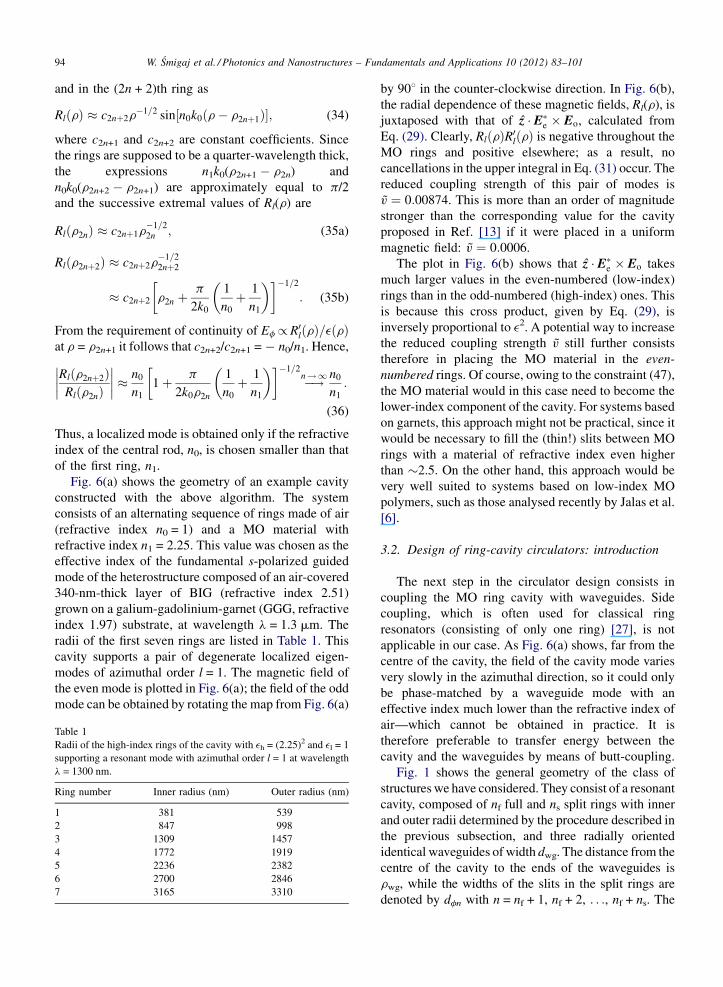
Fig. 6. (a) Magnetic field Hz of the even eigenmode of azimuthal order
l = 1 and wavelength l = 1300 m supported by the cavity composed of
an alternating sequence of rings made of air and a MO material with
refractive index 2.25. (b) Radial dependence of the magnetic field Hz
of the cavity eigenmodes and of the cross product of their electric
fields. Both functions are normalized to their maximum values. The
areas filled with the MO material are shaded.
formula for the mode coupling strength V of a cavity
containing a MO material polarized in the z direction.
Such a material is characterized by the permittivity
tensor
e ¼e ig 0
�ig e 0
0 0 e
24
35; (22)
where g, proportional to the material’s magnetization, is
the gyroelectric index. From now on we shall assume g
to be real. Together with the real-valuedness of e this is a
necessary condition for a Hermitian e and thus a lossless
MO material. Wang and Fan [23] obtained3
V � iV ¼ � i
2
v0
RgðrÞz � ½E�eðrÞ � EoðrÞ� drffiffiffiffiffiffiffiffiffiffiffiffiffiffiffiffiffiffiffiffiffiffiffiffiffiffiffiffiffiffiffiffiffiffiffiffiffiffiffiffiffiffiffiffiffiffiffiffiffiffiffiffiffiffiffiffiffiffiffiffiffiffiffiffiR
eðrÞjEoðrÞj2drR
eðrÞjEeðrÞj2 dr
q ;
(23)
where the integrals run over the whole cavity volume,
Ee and Eo are the electric fields of the even and odd
modes of the non-magnetized cavity, and v0 is their
frequency. Thus, V is proportional to the cross product
of E�e and Eo weighted by the off-diagonal component of
the permittivity tensor, ig.
It is convenient to introduce the dimensionless
reduced MO coupling strength v defined as
jVj=ðv0jgjmaxÞ, where |g|max denotes the maximum
magnitude of g over the cavity volume. The parameter vdepends then solely on the geometry of the cavity and
not on the strength of the MO effect in the chosen
material. It can therefore be used to compare the merits
of cavities with different geometries.
By exploiting the analytical properties of the
eigenmodes of the Helmholtz equation in axisymmetric
geometries, we will now derive a general design
strategy for resonant 2D cavities with large frequency
splitting in a uniform static external magnetic field. In
contrast to general PC cavities, circularly symmetric
cavities can be handled analytically, which makes it
possible to get a better insight into their properties.
We consider, then, a system of concentric rings [see
Fig. 6(a)], described by a piecewise-constant relative
permittivity e(r) independent of the azimuthal coordi-
nate f and the vertical coordinate z. The relative
permeability m is taken to be 1 everywhere. In the
p-polarization case [waves propagating in the (r, f)
plane with the magnetic field parallel to the z axis]
3 The difference in sign between Eq. (6) from Ref. [23] and Eq. (23)
here is caused by the difference in the convention chosen for harmonic
time-dependence (e�ivt here vs. eivt in Ref. [23]).
Maxwell’s equations
1
r
@Hz
@f¼ �ivee0Er; (24a)
@Hz
@r¼ ivee0Ef; (24b)
@Ef
@rþ 1
rEf �
1
r
@Er
@f¼ ivm0Hz (24c)
reduce to the Helmholtz equation for the z component of
the magnetic field, Hz:
e@
@r
1
e
@Hz
@r
�þ 1
r
@Hz
@rþ 1
r2
@2Hz
@f2þ e
v2
c2Hz ¼ 0:
(25)
Here v denotes the frequency, e0 and m0 the permittivity
and permeability of free space, and c ¼ 1=ffiffiffiffiffiffiffiffiffiffie0m0
pthe
speed of light in vacuum. Using separation of variables

W. Smigaj et al. / Photonics and Nanostructures – Fundamentals and Applications 10 (2012) 83–101 93
one can show that the eigenmodes of the system occur in
degenerate pairs of ‘‘even’’ and ‘‘odd’’ modes with
magnetic field of the general form
Hzeðr; fÞ ¼ RlðrÞ cosðlfÞ and Hzoðr; fÞ
¼ RlðrÞ sinðlfÞ; (26)
respectively, where the azimuthal order l is an integer
and the radial dependence Rl(r) is a solution of
eðrÞ @
@r
1
eðrÞ@Rl
@r
� �þ 1
r
@Rl
@r
þ eðrÞk20 1 � l2
eðrÞk20r
2
� �RlðrÞ ¼ 0; (27)
which reduces to the Bessel equation within each
uniform ring. In the above equation k0 � v/c is the
free-space wave number. Within each ring, Rl(r) can
then be expressed as a superposition of the Bessel
functions of the first and second kind:
RlðrÞ ¼ amJlðnmk0rÞ þ bmYlðnmk0rÞ; (28)
where m is the ring’s number, nmð � ffiffiffiffiffiemp Þ its refractive
index, and am and bm constant coefficients.
From Eq. (26) and Maxwell’s equations (24) we can
derive the general expressions for the cross product of
the electric fields corresponding to a pair of degenerate
modes with frequency v0 and azimuthal order l,
z � ðE�e � EoÞ ¼ lRlðrÞR0lðrÞv2
0re20½eðrÞ�
2; (29)
and for their squared norm,ZeðrÞjEeðrÞj2dr ¼
ZeðrÞjEoðrÞj2dr
¼ p
Z 10
l2½RlðrÞ�2 þ r2½R0lðrÞ�2
v20re2
0eðrÞdr; (30)
with R0lðrÞ denoting the derivative of Rl(r). Substituting
Eqs. (29) and (30) to the general formula for the
coupling strength (31), we obtain
V ¼ �iv0l
R10
gðrÞRlðrÞR0lðrÞeðrÞ2 drR1
0
l2½RlðrÞ�2þr2½R0lðrÞ�2
reðrÞ dr: (31)
Clearly, the sign of the integrand in the numerator of the
above expression depends on the sign of the product
gðrÞR0lðrÞR0lðrÞ. In general, this sign will oscillate due
to the oscillatory behaviour of the function Rl(r) itself.
Therefore, to avoid unnecessary cancellations in the
integral in question, the ring boundaries need to be
placed so that the product gðrÞRlðrÞR0lðrÞ be always
nonnegative (or nonpositive). Short of introducing in-
versely magnetized domains, this can only be achieved
by ensuring that the boundaries between the MO and
non-MO material coincide with the zeros of the product
RlðrÞR0lðrÞ, i.e. the zeros and extrema of Rl(r). With this
design principle in mind, we offer the following method
for the determination of the radii of the alternating MO
and non-MO rings making up a cavity supporting a pair
of degenerate modes with azimuthal order l � 1 at a
particular frequency v0 = k0c.
As a first step, we determine the radius r0 of the
central rod (‘‘zeroth ring’’), assumed to have refractive
index n0. In this rod, the radial field dependence is
expressed solely by means of the Bessel function of the
first kind Jl(n0k0r), since Yl(n0k0r) has a singularity at
the origin. Hence, b0 = 0 and, since the global mode
amplitude is arbitrary, a0 can be set to 1. It is then
evident that the product RlðrÞR0lðrÞ in the central rod
will not change sign until the first extremum of the
Jl(n0k0r) function. Therefore we set r0 to the value of r
at which this extremum occurs.
The amplitudes a1 and b1 of the Bessel functions in
the first ring, having refractive index n1, can now be
determined from the condition of continuity of Hz and
Ef. The outer radius of the first ring, r1, should then be
chosen so as to coincide with the first zero of the
function a1Jl(n1k0r) + b1Yl(n1k0r) located in that ring:
this is where the product RlðrÞR0lðrÞ will again change
sign. By repeating this process, we obtain the radii of
the subsequent rings. The outer radii of the even rings
(with refractive index n0) coincide with the extrema of
the function Rl(r), and those of the odd rings (with
refractive index n1), with its zeros. Thus, the cavity
designed in this way resembles an annular Bragg
grating [21], with each layer a quarter-wavelength thick
(in the sense of the Bessel-function quasi-periodicity).
We now need to make sure that the field of the mode
constructed in this way is localized, i.e. that Rl(r)
decays as r tends to infinity. Let us estimate the ratio of
Rl(r) at its two successive extrema, located at r2n and
r2n+2, where n 1. The Bessel functions of large
arguments can be approximated by [26, Eqs. (9.2.1) and
(9.2.2)].
JlðxÞYlðxÞ
�
ffiffiffiffiffiffi2
px
rcos
sin
� x � p
2l � p
4
� �: (32)
By construction, the field in the (2n + 1)th ring, located
between r2n and r2n+1, behaves approximately as
RlðrÞ c2nþ1r�1=2 cos½n1k0ðr � r2nÞ�; (33)
W. Smigaj et al. / Photonics and Nanostructures – Fundamentals and Applications 10 (2012) 83–10194
and in the (2n + 2)th ring as
RlðrÞ c2nþ2r�1=2 sin½n0k0ðr � r2nþ1Þ�; (34)
where c2n+1 and c2n+2 are constant coefficients. Since
the rings are supposed to be a quarter-wavelength thick,
the expressions n1k0(r2n+1 � r2n) and
n0k0(r2n+2 � r2n+1) are approximately equal to p/2
and the successive extremal values of Rl(r) are
Rlðr2nÞ c2nþ1r�1=22n ; (35a)
Rlðr2nþ2Þ c2nþ2r�1=22nþ2
c2nþ2 r2n þp
2k0
1
n0
þ 1
n1
�� ��1=2
: (35b)
From the requirement of continuity of Ef/ R0lðrÞ=eðrÞat r = r2n+1 it follows that c2n+2/c2n+1 = � n0/n1. Hence,
Rlðr2nþ2ÞRlðr2nÞ
�������� n0
n1
1 þ p
2k0r2n
1
n0
þ 1
n1
�� ��1=2
�!n ! 1 n0
n1
:
(36)
Thus, a localized mode is obtained only if the refractive
index of the central rod, n0, is chosen smaller than that
of the first ring, n1.
Fig. 6(a) shows the geometry of an example cavity
constructed with the above algorithm. The system
consists of an alternating sequence of rings made of air
(refractive index n0 = 1) and a MO material with
refractive index n1 = 2.25. This value was chosen as the
effective index of the fundamental s-polarized guided
mode of the heterostructure composed of an air-covered
340-nm-thick layer of BIG (refractive index 2.51)
grown on a galium-gadolinium-garnet (GGG, refractive
index 1.97) substrate, at wavelength l = 1.3 mm. The
radii of the first seven rings are listed in Table 1. This
cavity supports a pair of degenerate localized eigen-
modes of azimuthal order l = 1. The magnetic field of
the even mode is plotted in Fig. 6(a); the field of the odd
mode can be obtained by rotating the map from Fig. 6(a)
Table 1
Radii of the high-index rings of the cavity with eh = (2.25)2 and el = 1
supporting a resonant mode with azimuthal order l = 1 at wavelength
l = 1300 nm.
Ring number Inner radius (nm) Outer radius (nm)
1 381 539
2 847 998
3 1309 1457
4 1772 1919
5 2236 2382
6 2700 2846
7 3165 3310
by 908 in the counter-clockwise direction. In Fig. 6(b),
the radial dependence of these magnetic fields, Rl(r), is
juxtaposed with that of z � E�e � Eo, calculated from
Eq. (29). Clearly, RlðrÞR0lðrÞ is negative throughout the
MO rings and positive elsewhere; as a result, no
cancellations in the upper integral in Eq. (31) occur. The
reduced coupling strength of this pair of modes is
v ¼ 0:00874. This is more than an order of magnitude
stronger than the corresponding value for the cavity
proposed in Ref. [13] if it were placed in a uniform
magnetic field: v ¼ 0:0006.
The plot in Fig. 6(b) shows that z � E�e � Eo takes
much larger values in the even-numbered (low-index)
rings than in the odd-numbered (high-index) ones. This
is because this cross product, given by Eq. (29), is
inversely proportional to e2. A potential way to increase
the reduced coupling strength v still further consists
therefore in placing the MO material in the even-
numbered rings. Of course, owing to the constraint (47),
the MO material would in this case need to become the
lower-index component of the cavity. For systems based
on garnets, this approach might not be practical, since it
would be necessary to fill the (thin!) slits between MO
rings with a material of refractive index even higher
than �2.5. On the other hand, this approach would be
very well suited to systems based on low-index MO
polymers, such as those analysed recently by Jalas et al.
[6].
3.2. Design of ring-cavity circulators: introduction
The next step in the circulator design consists in
coupling the MO ring cavity with waveguides. Side
coupling, which is often used for classical ring
resonators (consisting of only one ring) [27], is not
applicable in our case. As Fig. 6(a) shows, far from the
centre of the cavity, the field of the cavity mode varies
very slowly in the azimuthal direction, so it could only
be phase-matched by a waveguide mode with an
effective index much lower than the refractive index of
air—which cannot be obtained in practice. It is
therefore preferable to transfer energy between the
cavity and the waveguides by means of butt-coupling.
Fig. 1 shows the general geometry of the class of
structures we have considered. They consist of a resonant
cavity, composed of nf full and ns split rings with inner
and outer radii determined by the procedure described in
the previous subsection, and three radially oriented
identical waveguides of width dwg. The distance from the
centre of the cavity to the ends of the waveguides is
rwg, while the widths of the slits in the split rings are
denoted by dfn with n = nf + 1, nf + 2, . . ., nf + ns. The

W. Smigaj et al. / Photonics and Nanostructures – Fundamentals and Applications 10 (2012) 83–101 95
rings and waveguides are made of a MO material with
permittivity
eh ¼eh ig 0
�ig eh 0
0 0 eh
24
35 (37)
and are embedded in an isotropic medium with permit-
tivity el.
In our simulations, the permittivities eh and el were
chosen as in the previous subsection, i.e. as eh = (2.25)2
and el = 1. A Faraday rotation of 10–208/mm has been
measured in BIG at l = 620 nm [19]. The tail of the
Faraday spectrum in this reference approaches a couple
of deg/mm, which corresponds to g � 0.05 � 0.1, close
to the near-infrared part of the spectrum. To assess the
maximum performance that can in principle be
achieved, we fixed g = 0.1.
The level of coupling between the cavity and
waveguide modes, and hence the circulator’s perfor-
mance, depends of course on the values of all the
geometrical parameters, which should therefore be
optimized. The space spanned by them is rather large,
and it is not possible to scan it exhaustively. Therefore
our optimization of the presented structure has been
somewhat heuristic. The waveguide width dwg was fixed
to 250 nm. The radii of the MO rings, listed in Table 1,
were determined with the procedure described in the
previous subsection to ensure the existence of a pair of
cavity modes with the azimuthal order l = 1 at the
wavelength l = 1300 nm.
With the chosen value of g, the relative frequency
splitting of these modes is Dv=v0 ¼ 2gv ¼ 0:00175.
From Eq. (18), in the absence of losses the optimum
value of g/v0 is 0.00151, i.e. the quality factor Q � v0/
(2g) describing the cavity-waveguide coupling should
be Q = 330. The quality factors of the chosen cavity
with 3 and 4 rings are 163 and 829, respectively.4
Therefore one can expect that the waveguides of an
optimally designed circulator should end somewhere
close to the third innermost ring—or possibly even
inside it, since the coupling to waveguides is doubt-
lessly less efficient than that to the whole surrounding
free space.
The total number of rings necessary for ensuring a
prescribed level of peak transmission Tmin could in
4 All the quality factors mentioned here and in the subsequent
paragraph were found by searching numerically for non-trivial solu-
tions of the homogeneous system of equations obtained by imposing
the conditions of continuity of Hz and Ef on the boundaries of the
rings.
principle be estimated from Eq. (21): for instance, for
Tmin = 0.9 the quality factor Qr describing radiation loss
should be greater than 6430. This is already ensured by
a 6-ring cavity, whose quality factor reaches 21,140.
However, the quality factors of cavities with split outer
rings will necessarily be smaller than of those with full
rings; therefore, a larger number of rings might be
necessary to ensure a 90-percent efficiency. In our
calculations, we restricted our attention to systems with
at most 7 rings.
Having fixed the number of split and full rings of the
circulator in this way, we were essentially left with the
problem of optimizing the values of dfn and rwg. The
ultimate figure of merit, the bandwidth, is nonzero only
for structures already rather close to optimum, which
makes it a cumbersome objective function. Therefore
we optimized instead the maximum isolation level,
hoping that circulators with large values of this
parameter would also be characterized by a large
bandwidth.
Numerical calculations of the transmission through
the circulators studied in this section were performed
with the finite-element method (FEM) using the RF
module of the COMSOL software package. To account
for the presence of idealized semi-infinite waveguides,
the computational domain, shown in Fig. 7, was
constructed as follows. The region surrounded by the
dashed line is a fragment of the physical system shown
in Fig. 1. The parts of its boundary lying ‘‘far’’ from the
waveguide ends are covered with perfectly matched
layers (PMLs) implemented by means of the complex
coordinate transform r 7! sPML(1 + i)(r � rin)/dPML,
where r is the radial coordinate measured form the
centre of the cavity, rin denotes the radius of the inner
Fig. 7. Geometry of the domain used in FEM calculations.

W. Smigaj et al. / Photonics and Nanostructures – Fundamentals and Applications 10 (2012) 83–10196
Fig. 8. (a) Magnitude of the magnetic field in circulator C1 at the
wavelength l = 1300.0 nm, corresponding to the maximum isolation
level. The waveguide mode is incident from the left. (b) Wavelength
dependence of the transmission (left axis) and isolation level (right
axis) of C1.
PML boundary, dPML = 600 nm is the PML thickness,
and sPML = l its strength. The radius rin is chosen so
that the distance from the outermost ring to the inner
PML boundary is dsep = 5000 nm. Perfect-electric-
conductor boundary conditions are imposed on the parts
of the domain’s boundary adjacent to the PML. In
constrast, the electromagnetic fields on the segments Pn
(n = 1, 2, 3) of length dport = 2250 nm, perpendicular to
the waveguides, are constrained to be a superposition of
the incoming and outgoing guided modes of the
corresponding waveguides. The profile of these modes
is calculated analytically and normalized to unitary
power, and the amplitude of the incoming mode is set to
unity on P1 and to zero on P2 and P3. Physically, these
constraints correspond to the assumption that all the
radiative waveguide modes excited by the cavity decay
before reaching the ports Pn. The domain is divided into
triangular nodal Lagrangian elements of order p = 5 and
maximum allowed size hmax=ffiffiffiep
, where hmax = 500 nm
and e is the local permittivity.
We have verified that above choice of the computa-
tional parameters allows to calculate the 20-dB-
bandwidth of typical circulators with an accuracy of
about 3% (see Ref. [28], Section 4.5.2, for a detailed
convergence study).
3.3. Design of ring-cavity circulators: geometry
optimization
We initially focused on circulators with dfn
independent from n, i.e. with waveguides enclosed in
rectangular ‘‘slits’’ of width df. The contours in
Fig. 8(a) show the geometry of the best structure we
have found, called 2.4 in the following. It has 3 full and
4 split rings. The slit width df = 1770 nm and the
waveguide ends are located at rwg = 1240 nm from the
cavity centre, so that the waveguides cross the
outermost full ring. For ease of reference, the values
of all the geometrical parameters of C1 are listed in
Table 2. This circulator offers maximum isolation level
of 35 dB, and the wavelength dependences of T2, T3 and
I are shown in Fig. 8(b). Clearly, the curves are fairly
symmetric with respect to the central wavelength
l = 1300.0 nm, which indicates that the direct coupling
between waveguides is insignificant. Fig. 8(c) shows the
Table 2
Geometrical parameters of the circulators analysed in the text. The ring ra
Circulator nf ns rwg (nm)
C1 3 4 1240
C2 3 4 1210
map of the magnetic field at l = 1300.0 nm. At this
wavelength, 88% of the input power is transmitted to
waveguide 2; the rest is mainly lost to the surrounding
free space. Far from the peak, the amount of these losses
can exceed 50%. This behaviour contrasts with that of
the PC circulator, where almost 100% of the input
power remains in the waveguide system due to the
quasi-perfect isolation provided by the surrounding
periodic lattice. The 20-dB bandwidth B(20 dB) of
circulator C1 is 0.729 nm (129 GHz).
The grey curves in Fig. 8(b) show the transmittance
curves of this circulator as predicted by the coupled-
wave model with radiation losses taken into account,
presented in Section 2.4. The values of the parameters
v0, Dv, g and gr were found by fitting the expressions
for T2 and T3 obtained from Eq. (17) to the values
dii are listed in the first (nf + ns) rows of Table 1.
df (nm) fcone (8) Slits
1770 – Rectangular
– 35.1 Conical

W. Smigaj et al. / Photonics and Nanostructures – Fundamentals and Applications 10 (2012) 83–101 97
Fig. 10. Wavelength dependence of the transmission (left axis) and
isolation level (right axis) of circulator C2 (inset) with waveguides
enclosed in conical slits.
calculated numerically. The Levenberg–Marquardt
algorithm was used as the fitting procedure. The best
fit was obtained for parameters corresponding to
l0 � 2pc/v0 = 1299.9 nm, Dl � 2pcDv=v20 ¼ 2:3 nm,
Q � v0/(2g) = 370 and Qr � v0/(2gr) = 5730. Clearly,
there is a good match between the theoretical and
numerical curves; its quality would probably be further
improved by taking into account the direct coupling
between waveguides, which causes the slight asym-
metry of the numerical plots. The quality factor related
to losses, Qr, is significantly lower than that of an
isolated cavity with 7 full rings, which is as large as
107,000. This is obviously due to the presence of slits.
On the other hand, the position of the ends of the
waveguides (just inside the third innermost ring) is in
good accord with the predictions made in Section 3.2.
We have found this device very tolerant to variations
of the slit width df; Fig. 9(a) and (b) shows the
dependence of the maximum isolation level and
bandwidth of 2.4 on this parameter. It can be seen
that the bandwidth stays above 0.5 nm in a 300-nm-
wide range of df. The constraints on rwg are more
stringent: as shown in Fig. 9(c), the corresponding range
of rwg is about 40-nm wide.
The performance of this structure changes rather
abruptly when the number of rings is modified. For
instance, if the seventh ring is removed, the maximum
isolation level decreases to only 21 dB and the
bandwidth to 0.386 nm (69 GHz). However, it is
possible to improve these figures by readjusting the
slit widths and the position of the waveguide ends: for
rwg = 1250 nm and df = 1570 nm (10% less than in the
7-ring case) Imax reaches 33 dB and the bandwidth
0.603 nm (107 GHz).
Fig. 9. Tolerance of the bandwidth B (20 dB) and the maximum
isolation level Imax of circulator C1 to perturbations of the parameters
(a and b) df and (c and d) rwg.
Having noted that both for 6 and 7 rings the optimum
angular length of the removed sectors of the outermost
ring is almost the same, �348, we now wish to test the
performance of a second class of structures, in which
the outer rings are truncated along radial lines instead of
ones parallel to the waveguides. The latter are thus
enclosed by conical rather than rectangular air slits, as
illustrated in the inset of Fig. 10. We found the optimum
cone aperture fcone to be 35.18, close to the value cited
above. The optimum position of the waveguide end,
rwg = 1210 nm, is also only slightly different from the
original one. More importantly, the maximum isolation
level and bandwidth decrease much less (from 35 to
28 dB and from 0.770 to 0.708 nm, or 137 to 126 GHz,
respectively) when the seventh ring is removed. This
relative insensitivity to the details of the geometrical
structure of the exterior region of the device is the
behaviour that one would intuitively expect from a well-
designed circulator; therefore, structures with conical
slits seem closer to the ideal than those with rectangular
ones. Fig. 10 shows the wavelength dependence of T2,
T3 and I of the optimum 7-ring circulator with conical
slits, referred to as C2. Its parameters are listed in Table
2.
4. Perspectives—towards 3D nonreciprocal
cavities
4.1. High-contrast 3D cavities
It is well known that the properties of a 3D cavity
depend crucially on its vertical multilayer profile, and a
cavity with a high Q in 2D can leak heavily in 3D if the
presence of the substrate and superstrate is not taken
into account. The design algorithm of Section 3.1 is
based on 2D considerations, and a similar algorithm in
3D is nearly impossible to develop. However, the 2D

W. Smigaj et al. / Photonics and Nanostructures – Fundamentals and Applications 10 (2012) 83–10198
Table 3
Relative frequency splitting Dv/v0 and quality factor Q of the
eigenmodes of several G1- and G2-type 20-ring cavities designed
to support modes of azimuthal order �l. The values obtained with
rigorous 3D FEM calculations are compared to the estimates obtained
with 2D calculations in the framework of the effective-index approxi-
mation. Note that Q is defined as the average of the quality factors of
the modes with aximuthal order l and �l.
algorithm has allowed us to compare our designs to
previously reported circulator cavities [13,23,29]. So
far, the true 3D nature of a real integrated system has
only been taken into account in our work by using an
effective-index approximation for the unetched MO
rings. The material between the rings has, however,
always been set to be air—an approach that is
reasonable only if the garnet layer is entirely etched
away between the MO rings. Such a high-contrast ring
cavity cannot, however, be fabricated in a membrane
form, since the rings are not interconnected. Therefore,
in practice the rings will need to be placed on a solid
substrate with refractive index nsub. Far from its centre,
the ring cavity can be locally approximated by a linear
grating with period:
L ¼ l
4
1
n0
þ 1
n1
�: (38)
If L > l/2nsub, all Bloch eigenmodes of the grating will
leak into the substrate. In order to avoid that fate, nsub
must be smaller than l/2L. For n0 = 1, n1 = 2.25 and
l = 1300 nm, the substrate index must be less than 1.4.
This might prove very difficult to achieve.
4.2. Low-contrast 3D cavities
In low-index-contrast cavities substrate leakage is
much easier to avoid, albeit at the price of larger cavity
due to smaller Bragg gap. This can be seen by rewriting
the no-leakage condition as nsub/2 < neff,0neff,1/
(neff,0 + neff,1). This condition is always met if both
effective indices are larger than the substrate index nsub,
around 1.9 for typical garnet substrates (such as GGG).
We have considered two classes of low-contrast
cavities. In one of them, shown in Fig. 11(a) and
labelled G1 henceforth, the garnet layer
(dBIG = 280 nm) is left unetched and the cavity is
formed by etching in a high-index cladding layer
(nspl = 3.5, dspl = 80 nm). The MO properties of the
exposed BIG regions are assumed to be destroyed by
e.g. ion implantation. In the second class of cavities,
shown in Fig. 11(b) and referred to as G2, rings etched
Fig. 11. Schematics of 3D structures of types (a) G1 and (b) G2.
in BIG (dBIG = 330 nm) are buried in a material with
index nsup approximately equal to that of the GGG
substrate. A potential candidate is silicon nitride
(Si3N4); around l = 1300 nm, the refractive index of
both GGG and Si3N4 is 1.97. As indicated above, the
use of the effective-index approximation to determine
the position and width of the rings by help of the
algorithm of Section 3.1 is now better justifiable. We
have used an in-house-developed rigorous FEM code
[28, Section 5.3] to compute the resonant frequencies of
axisymmetric 3D cavities belonging to the just
described classes, crosschecking the data obtained with
the 2D model. Table 3 summarizes the results of these
calculations.
They prove first of all that the 2D design procedure is
flexible enough to let us adapt it to 3D layouts. The
frequency splittings calculated with the FEM code are
only slightly reduced with respect to those predicted by
the 2D model. In fact this decrease can be entirely
attributed to a reduced mode confinement in the MO
layer due to the vertical permittivity profile. The more
worrying aspect, however, is the strong diminution of
the quality factor. The quality factors of the 3D cavities
are an order of magnitude smaller than those obtained
with 2D calculations (for the same number of rings and
related only to the in-plane confinement).
The negative impact of large radiation losses (and
thus low Q factors) on the operation of the non-
reciprocal cavity can be easily understood by consider-
ing the following equations of the coupled-mode model
including radiation losses:
s3;out ¼ � 2
3
g½g þ gr � Vffiffiffi3p� iðv � v0Þ�
½g þ gr � iðv � v0Þ�2 þ V2; (39a)
Type l Dv/v0 (3D) Dv/v0 (2D) Q (3D) Q (2D)
G1 1 0.00129 0.00166 104 1277
4 0.00200 0.00286 105 1410
10 0.00227 0.00342 109 1360
G2 1 0.00138 0.00207 134 2079
4 0.00213 0.00349 172 2285
10 0.00241 0.00412 334 2139
G2a 10 0.00261 – 2420 –
a After numerical optimization of ring radii.

– Fundamentals and Applications 10 (2012) 83–101 99
Fig. 12. Magnitude of the z component of the magnetic field of the
eigenmode of (a) the original G2-type cavity designed for l = 10, and
of (b) its numerically optimized version; both in the absence of
magnetization. The rectangles denote the cross-sections of BIG rings
immersed in a material with refractive index 1.97. The improved field
confinement (and thus higher Q) is easily seen. The MO interaction
described by the cross product E�e � Eo (not shown here) is almost not
influenced.
1
Qþ 1
Qr
¼ Dv
v0
ffiffiffi3p
; (39b)
where Q and Qr describe respectively the ‘‘useful’’
cavity-waveguide coupling and the radiation loss.
The latter equation is obtained by rewriting Eq. (18)
using 2jVj ¼ Dv and the definition of the quality factor
Q � v0/2g. For simplicity only the case without direct
coupling D ¼ p2
� is considered. Eq. (39b) expresses the
optimum relationship between the relative frequency
splitting and the two Q factors. It implies that for a
radiative quality factor Qr lower than v0=ðDvffiffiffi3pÞ
perfect circulation cannot occur, since it would require
a negative (unphysical) value of Q. For such small Qr
the coupling necessarily becomes overcritical, i.e.
gr + g is larger than the optimum value.
Fig. 2(a) shows that the circulator has some tolerance
with respect to g. At a 10-percent overtuning (g � 2jVj)maximum isolation level of �20 dB is still possible.
This will of course come at the price of a heavily
reduced transmission level. Indeed, assuming a modest
overtuning (in order to keep the isolation level
reasonable), from Eq. (39a) we obtain
max T3� maxjs3;outj2� ðg=ffiffiffi3p
VÞ2, with g ¼ v0= 2Qð Þdescribing the cavity-waveguide coupling alone. Thus,
a ten-percent overtuning with Qr � v0=ðDvffiffiffi3pÞ and
Q � 0:1 v0=ðDvffiffiffi3pÞ would lead to transmission levels
of about 1%.
4.3. Towards low-contrast nonreciprocal cavities
with higher quality factor
Table 3 shows that none of the 3D cavities under
consideration supports a dipolar (l = 1) mode with
an inverse radiation quality factor 1/Qr smaller
than 400% of the optimum coupling strength,
Dvffiffiffi3p
=v0. The most direct way to increase Qr consists
in moving towards designs for higher azimuthal orders
l. The stronger azimuthal variation leads to higher in-
plane k-components in the cavity mode and thus lower
substrate leakage. Conveniently, according to (31), the
relative frequency splitting also increases with azi-
muthal order. The price to pay is a higher modal
volume. Table 3 shows nevertheless that the increase in
Qr is limited. The best cavity designed for l = 10, the
one belonging to the class 4, supports a mode with
1/Qr of about 70% of the optimum coupling
strength Dvffiffi3p
v0. As a result, at optimum coupling, g ¼
v0=2ð Þ 1=Qð Þ � v0=2ð Þ0:3 Dv=v0ð Þffiffiffi3p¼ 0:3
ffiffiffi3pjVj
and one still cannot expect transmission levels larger
than 10% in the best-case scenario.
W. Smigaj et al. / Photonics and Nanostructures
We have recently applied a numerical optimization
procedure to adjust the positions and widths of the rings.
In a first attempt this has already led to an improved
design for a 20-ring G2-type cavity (for an l = 10 mode).
Fig. 12 shows the geometry of the original and the
optimized G2-type cavity, as well as the maps of the
normalized magnetic field of their modes. The Q factor
of the mode of the optimized cavity is as large as 2420:
an increase by almost an order of magnitude from 334.
Moreover, it is higher than that of the mode of the
original 2D 20-ring cavity, 2139. This means that the Q
factor of the optimized cavity is constrained by in-plane
rather than out-of-plane radiation loss, and so it could be
further augmented if necessary by increasing the
number of rings. At the same time, the relative
frequency splitting stays quite tolerant with respect to
this optimization, indicating that as far as MO effect
goes the 2D design algorithm proposed here is already
quasi-optimal. The obtained Dv/v0 is 0.00261, even
slightly larger than in the original structure. Using
similar estimations as above, these values imply that in a
best-case scenario perfect circulation with a maximal
transmission close to 90% is possible. The total device
footprint remains close to (10l)2. This work together
with a 3D analysis of the waveguide-cavity coupling
problem will be the subject of a future communication.
5. Conclusion
In this work we have presented an extensive study of
a new concept for a very compact and technologically
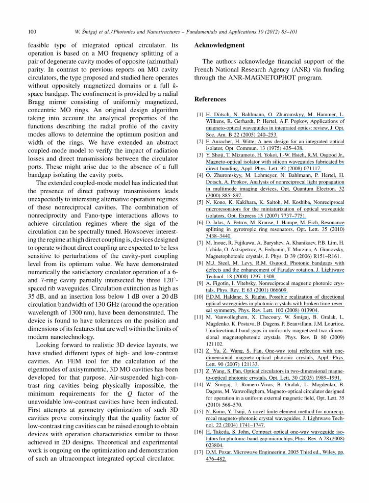
W. Smigaj et al. / Photonics and Nanostructures – Fundamentals and Applications 10 (2012) 83–101100
feasible type of integrated optical circulator. Its
operation is based on a MO frequency splitting of a
pair of degenerate cavity modes of opposite (azimuthal)
parity. In contrast to previous reports on MO cavity
circulators, the type proposed and studied here operates
without oppositely magnetized domains or a full k-
space bandgap. The confinement is provided by a radial
Bragg mirror consisting of uniformly magnetized,
concentric MO rings. An original design algorithm
taking into account the analytical properties of the
functions describing the radial profile of the cavity
modes allows to determine the optimum position and
width of the rings. We have extended an abstract
coupled-mode model to verify the impact of radiation
losses and direct transmissions between the circulator
ports. These might arise due to the absence of a full
bandgap isolating the cavity ports.
The extended coupled-mode model has indicated that
the presence of direct pathway transmissions leads
unexpectedly to interesting alternative operation regimes
of these nonreciprocal cavities. The combination of
nonreciprocity and Fano-type interactions allows to
achieve circulation regimes where the sign of the
circulation can be spectrally tuned. Howsoever interest-
ing the regime at high direct coupling is, devices designed
to operate without direct coupling are expected to be less
sensitive to perturbations of the cavity-port coupling
level from its optimum value. We have demonstrated
numerically the satisfactory circulator operation of a 6-
and 7-ring cavity partially intersected by three 1208-spaced rib waveguides. Circulation extinction as high as
35 dB, and an insertion loss below 1 dB over a 20 dB
circulation bandwidth of 130 GHz (around the operation
wavelength of 1300 nm), have been demonstrated. The
device is found to have tolerances on the position and
dimensions of its features that are well within the limits of
modern nanotechnology.
Looking forward to realistic 3D device layouts, we
have studied different types of high- and low-contrast
cavities. An FEM tool for the calculation of the
eigenmodes of axisymmetric, 3D MO cavities has been
developed for that purpose. Air-suspended high-con-
trast ring cavities being physically impossible, the
minimum requirements for the Q factor of the
unavoidable low-contrast cavities have been indicated.
First attempts at geometry optimization of such 3D
cavities prove convincingly that the quality factor of
low-contrast ring cavities can be raised enough to obtain
devices with operation characteristics similar to those
achieved in 2D designs. Theoretical and experimental
work is ongoing on the optimization and demonstration
of such an ultracompact integrated optical circulator.
Acknowledgment
The authors acknowledge financial support of the
French National Research Agency (ANR) via funding
through the ANR-MAGNETOPHOT program.
References
[1] H. Dotsch, N. Bahlmann, O. Zhuromskyy, M. Hammer, L.
Wilkens, R. Gerhardt, P. Hertel, A.F. Popkov, Applications of
magneto-optical waveguides in integrated optics: review, J. Opt.
Soc. Am. B 22 (2005) 240–253.
[2] F. Auracher, H. Witte, A new design for an integrated optical
isolator, Opt. Commun. 13 (1975) 435–438.
[3] Y. Shoji, T. Mizumoto, H. Yokoi, I.-W. Hsieh, R.M. Osgood Jr.,
Magneto-optical isolator with silicon waveguides fabricated by
direct bonding, Appl. Phys. Lett. 92 (2008) 071117.
[4] O. Zhuromskyy, M. Lohmeyer, N. Bahlmann, P. Hertel, H.
Dotsch, A. Popkov, Analysis of nonreciprocal light propagation
in multimode imaging devices, Opt. Quantum Electron. 32
(2000) 885–897.
[5] N. Kono, K. Kakihara, K. Saitoh, M. Koshiba, Nonreciprocal
microresonators for the miniaturization of optical waveguide
isolators, Opt. Express 15 (2007) 7737–7751.
[6] D. Jalas, A. Petrov, M. Krause, J. Hampe, M. Eich, Resonance
splitting in gyrotropic ring resonators, Opt. Lett. 35 (2010)
3438–3440.
[7] M. Inoue, R. Fujikawa, A. Baryshev, A. Khanikaev, P.B. Lim, H.
Uchida, O. Aktsipetrov, A. Fedyanin, T. Murzina, A. Granovsky,
Magnetophotonic crystals, J. Phys. D 39 (2006) R151–R161.
[8] M.J. Steel, M. Levy, R.M. Osgood, Photonic bandgaps with
defects and the enhancement of Faraday rotation, J. Lightwave
Technol. 18 (2000) 1297–1308.
[9] A. Figotin, I. Vitebsky, Nonreciprocal magnetic photonic crys-
tals, Phys. Rev. E 63 (2001) 066609.
[10] F.D.M. Haldane, S. Raghu, Possible realization of directional
optical waveguides in photonic crystals with broken time-rever-
sal symmetry, Phys. Rev. Lett. 100 (2008) 013904.
[11] M. Vanwolleghem, X. Checoury, W. Smigaj, B. Gralak, L.
Magdenko, K. Postava, B. Dagens, P. Beauvillain, J.M. Lourtioz,
Unidirectional band gaps in uniformly magnetized two-dimen-
sional magnetophotonic crystals, Phys. Rev. B 80 (2009)
121102.
[12] Z. Yu, Z. Wang, S. Fan, One-way total reflection with one-
dimensional magneto-optical photonic crystals, Appl. Phys.
Lett. 90 (2007) 121133.
[13] Z. Wang, S. Fan, Optical circulators in two-dimensional magne-
to-optical photonic crystals, Opt. Lett. 30 (2005) 1989–1991.
[14] W. Smigaj, J. Romero-Vivas, B. Gralak, L. Magdenko, B.
Dagens, M. Vanwolleghem, Magneto-optical circulator designed
for operation in a uniform external magnetic field, Opt. Lett. 35
(2010) 568–570.
[15] N. Kono, Y. Tsuji, A novel finite-element method for nonrecip-
rocal magneto-photonic crystal waveguides, J. Lightwave Tech-
nol. 22 (2004) 1741–1747.
[16] H. Takeda, S. John, Compact optical one-way waveguide iso-
lators for photonic-band-gap microchips, Phys. Rev. A 78 (2008)
023804.
[17] D.M. Pozar. Microwave Engineering, 2005 Third ed., Wiley, pp.
476–482.

W. Smigaj et al. / Photonics and Nanostructures – Fundamentals and Applications 10 (2012) 83–101 101
[18] S. Visnovsky, Optics in Magnetic Multilayers and Nanostructures,
CRC, 2006.
[19] B. Vertruyen, R. Cloots, J.S. Abell, T.J. Jackson, R.C. da Silva, E.
Popova, N. Keller, Curie temperature, exchange integrals, and
magneto-optical properties in off-stoichiometric bismuth iron
garnet epitaxial films, Phys. Rev. B 78 (2008) 094429.
[20] S. Schonenberger, N. Moll, T. Stoferle, R.F. Mahrt, B.J. Offrein,
S. Gotzinger, V. Sandoghdar, J. Bolten, T. Wahlbrink, T. Plotz-
ing, M. Waldow, M. Forst, Circular grating resonators as small
mode-volume microcavities for switching, Opt. Express 17
(2009) 5953–5964.
[21] J. Scheuer, Radial Bragg lasers: optimal design for minimal
threshold levels and enhanced mode discrimination, J. Opt. Soc.
Am. B 24 (2007) 2178–2184.
[22] W. Suh, Z. Wang, S. Fan, Temporal coupled-mode theory and the
presence of non-orthogonal modes in lossless multimode cavi-
ties, IEEE J. Quantum Electron. 40 (2004) 1511–1518.
[23] Z. Wang, S. Fan, Magneto-optical defects in two-dimensional
photonic crystals, Appl. Phys. B 81 (2005) 369–375.
[24] A. Miroshnichenko, S. Flach, Y. Kivshar, Fano resonances
in nanoscale structures, Rev. Mod. Phys. 82 (2010) 2257–
2298.
[25] J.D. Joannopoulos, S.G. Johnson, J.N. Winn, R.D. Meade,
Photonic Crystals: Molding the Flow of Light, Second ed.,
Princeton, 2008.
[26] M. Abramowitz, Handbook of Mathematical Functions, Dover,
1965.
[27] A. Yariv, Universal relations for coupling of optical power
between microresonators and dielectric waveguides, Electron.
Lett. 36 (2000) 321–322.
[28] W. Smigaj, Design and numerical modelling of integrated optical
components, Ph.D. thesis, Universite Paul Cezanne (Aix-Mar-
seille III), 2010. Available at http://tel.archives-ouvertes.fr/EC-
MARSEILLE/tel-00567213.
[29] Z. Wang, S. Fan, Suppressing the effect of disorders using time-
reversal symmetry breaking in magneto-optical photonic crys-
tals: an illustration with a four-port circulator, Photonics Nanos-
truct. Fundam. Appl. 4 (2006) 132–140.