A discrete retrial system with uniformly distributed service time

International Journal of Thermal Sciences 45 (2006) 932–937www.elsevier.com/locate/ijts
Developing upward flow in a uniformly heated circular ductunder transitional mixed convection
Walter Grassi ∗, Daniele Testi
LOTHAR (LOw gravity and THermal Advanced Research Laboratory), Department of Energetics “L. Poggi”, University of Pisa, via Diotisalvi 2, 56126 Pisa, Italy
Received 16 September 2005; received in revised form 31 October 2005; accepted 17 November 2005
Available online 19 January 2006
Abstract
Upward flow of perfluorohexane (FC-72) in the entry zone of a uniformly heated circular duct was studied in a regime of transitional combinedforced and free convection. Heat transfer coefficients were measured along the heated length at different values of flow rate and heat flux. Heattransfer impairment in the developing region due to laminarisation of the turbulent flow was observed and characterised by means of two well-known dimensionless groups: the Grätz number and the Grashof number based on the wall heat flux.© 2006 Elsevier SAS. All rights reserved.
Keywords: Mixed convection; Developing flow; Buoyancy; Entrance region; Heat transfer correlations; Laminarisation
1. Introduction
In a weakly forced pipe flow, the buoyant forces can be ofthe same order of magnitude as the inertial ones. In this con-dition of mixed convection, the hydrodynamic and the thermalfields are interdependent. The velocity and temperature profilesof the pure forced convection case are modified by buoyancy;moreover, turbulence arises much earlier: at Re ≈ 400 for ver-tical tubes and Re ≈ 1000 for horizontal ones, according to themaps proposed in [1].
The internal heat transfer characteristics in mixed convectionnot only depend on whether the flow is hydrodynamically orthermally developing, laminar or turbulent and on duct geome-try, but also on whether the fluid is cooled or heated and on ductorientation (horizontal or inclined, upflow or downflow).
1.1. Vertical aiding flow
In the vertical aiding configuration (heated upflow or cooleddownflow) laminarisation effects may be observed. The de-
* Corresponding author. Tels: +39 050 2217090, +39 050 2217109; fax: +39050 2217085.
E-mail addresses: [email protected] (W. Grassi), [email protected](D. Testi).
1290-0729/$ – see front matter © 2006 Elsevier SAS. All rights reserved.doi:10.1016/j.ijthermalsci.2005.11.007
Fig. 1. Velocity profiles under isothermal and aiding flow [2].
scription of the phenomenon is the following: when natural andforced convection act in the same direction, the fluid is accel-erated in the region close to the tube wall and, due to masscontinuity, retarded in the core (see Fig. 1).
According to Prandtl’s model of turbulence, heat transfer ismainly controlled by the diffusive energy transport from theborder of the viscous layer (in which the transfer is conduc-

W. Grassi, D. Testi / International Journal of Thermal Sciences 45 (2006) 932–937 933
Nomenclature
cp fluid specific heat . . . . . . . . . . . . . . . . . . J kg−1 K−1
D duct inner diameter . . . . . . . . . . . . . . . . . . . . . . . . . mg acceleration due to gravity . . . . . . . . . . . . . . . m s−2
Gr = βg(Tw_in−Tb)D3
ν2 , Grashof number based on thewall superheat
Grq Grashof number based on the wall heat fluxGz Grätz numberL duct heated length . . . . . . . . . . . . . . . . . . . . . . . . . . mm = ρV , mass flow rate . . . . . . . . . . . . . . . . . . . kg s−1
Nu Nusselt number〈Nu〉 azimuthal average of the Nusselt numberPr Prandtl numberq wall heat flux . . . . . . . . . . . . . . . . . . . . . . . . . . W m−2
Re Reynolds numbers duct thickness . . . . . . . . . . . . . . . . . . . . . . . . . . . . . . mT temperature . . . . . . . . . . . . . . . . . . . . . . . . . . . . . . . . Ku fluid velocity . . . . . . . . . . . . . . . . . . . . . . . . . . . m s−1
um mean velocity in the core of the flow . . . . . . m s−1
uε velocity at the rim of the viscous layer . . . . m s−1
V volumetric flow rate . . . . . . . . . . . . . . . . . . . . m3 s−1
x distance from the thermal inlet section . . . . . . . . mx∗ = Gz−1, normalised distance from the inlet
Greek symbols
α convective heat transfer coefficient . . W m−2 K−1
β coefficient of cubic expansion . . . . . . . . . . . . . K−1
η dynamic viscosity . . . . . . . . . . . . . . . . . . . . . . . . . Pa sλ fluid thermal conductivity . . . . . . . . . . W m−1 K−1
ν = ηρ
, kinematic viscosity . . . . . . . . . . . . . . . . m2 s−1
Θ heat flow . . . . . . . . . . . . . . . . . . . . . . . . . . . . . . . . . . Wρ mass density . . . . . . . . . . . . . . . . . . . . . . . . . . kg m−3
Subscripts
b bulkf filmi insulatorin inletout outletw wallw_in inner side of the heated wallw_out outer side of the heated wall
Fig. 2. Effect of buoyancy level on the velocity profile [2].
tive) to the core of the turbulent flow. The mentioned energytransport increases in accordance with the production of turbu-lence in the area close to the edge of the viscous layer, which,in turn, depends on the difference between the mean velocityin the core of the flow, um, and the velocity at the rim of theviscous layer, uε (see Fig. 2).
In the middle drawing of Fig. 2, the difference between um
and uε is close to zero, thus, the reduced turbulence produc-tion causes a laminarisation of the flow and a consequent heattransfer impairment. In a thermally developing flow, this phe-nomenon is likely to occur at a certain distance from the inlet,depending on the imposed flow rate and heat flux [3].
934 W. Grassi, D. Testi / International Journal of Thermal Sciences 45 (2006) 932–937
Table 1FC-72 physical properties at 25 ◦C and 1 bar
Freezing point −90 ◦CBoiling point 56 ◦CDensity 1.68 × 10³ kg m−3
Kinematic viscosity 3.8 × 10⁻⁷ m2 s−1
Specific heat 1.1 × 10³ J kg−1 K−1
Thermal conductivity 5.7 × 10⁻² W m−1 K−1
Coefficient of expansion 1.56 × 10⁻³ K−1
Although a comprehensive account of turbulent mixed con-vection can be found in [4], fundamental understanding of theheat transfer behaviour of combined free and forced convectionin the thermal entry region is very limited, in spite of the factthat in practical applications we rarely deal with a fully devel-oped flow.
2. Experimental apparatus
In the present work we analyse the developing regime ofmixed convection in a circular pipe positioned vertically, withupward flow.
2.1. Working fluid
The fluid chosen for the experimental campaign is perfluoro-hexane, a Fluorinert™ Electronic Liquid manufactured by 3M
(St. Paul, MN, USA), commercially named FC-72. The mainphysical properties of this dielectric liquid are reported in Ta-ble 1.
FC-72 is thermally and chemically stable, compatible withsensitive materials, non-flammable, non-toxic, colourless, andhas no ozone depletion potential. This combination of proper-ties, together with its particularly low viscosity, makes FC-72appropriate for applications like heat sinks for electronic com-ponents.
2.2. Test loop description
A test loop was built as shown in the schematic of Fig. 3.The fluid, moved by a gear pump, circulated through the
test specimen at volumetric flow rates in the range 0.26–1.04 lt min−1. A flowmeter measured the flow rate with anaccuracy of ±0.0086 lt min−1. The fluid, uniformly heated inits flow along the test section, was cooled to the desired in-let temperature by means of a shell-tube heat exchanger, withcountercurrent chilled water flowing in the shell. An expansionvessel was used to compensate the volume increase in the loopdue to temperature variations and to set the pressure of the po-sition it was mounted on. An absolute pressure transducer wasplaced right upstream of the gear pump, in order to check thatthe lowest pressure of the loop was above the room pressure,thus avoiding air from being sucked in by the pump. All thetests were performed at an inlet temperature of 20 ◦C and at anabsolute pressure of 2 bars.
Fig. 3. Schematic of the test loop.
2.3. Test section description
A detailed schematic of the test section is shown in Fig. 4.The pipe was made of stainless steel and had an inner di-
ameter D = 17.3 mm and a wall thickness s = 2 mm. After anabrupt contraction, a short unheated length (about 7 diameterslong) precedes the thermal entrance. The fluid was warmed upby an electrical resistance heater applied to the outer wall for alength L = 500 mm. The applied heat flow ranged from 30 to85 W.
Temperature measurements were made by type-T thermo-couples, placed on the outer wall, under the heater, at three crosssections along the heated length: respectively at x = 125 mm,x = 250 mm, and x = 375 mm, being x the distance from thebeginning of the heated length. Each cross section had four ther-mocouples, one every 90◦.
To minimize heat losses, the entire specimen was coveredwith a thermal insulator (λi = 0.038 W m−1 K−1). Two moretype-T thermocouples were placed at the inlet and at the outletof the test section, in order to evaluate the heat flow supplied insteady state through the energy balance:
Θ = mcp(Tout − Tin) (1)
having neglected the heat generated by viscous dissipationwithin the fluid.
All the thermocouples used a zero-point reference joint,whose temperature was controlled by a reference resistancethermometer. The overall accuracy of each thermocouple aftercalibration in the 15–60 ◦C range was ±0.2 K.
The available differential pressure transducer had a sensitiv-ity of 30 Pa and was not able to measure appreciable pressuredrops through the test section.
Further details on the experimental apparatus can be foundin [5].
3. Test procedure and data analysis
Every test was run under constant volumetric flow rate andheat flow and a steady state condition was awaited. The ther-

W. Grassi, D. Testi / International Journal of Thermal Sciences 45 (2006) 932–937 935
Fig. 4. Detail of the test section.
mocouples’ signals were acquired every 6 seconds by a scannermounted on a digital multimeter; then the data were sent to aPC in order to be recorded and processed.
The bulk temperature of the fluid at a given axial positionwas calculated considering a temperature of adiabatic mixingfor the examined cross section, assuming a linear trend, fromthe inlet to the outlet temperature, on the heated length. Thetemperatures of the inner side of the wall were obtained fromthe ones measured on the outer face, properly accounting forone-dimensional heat conduction within the duct thickness:
Tw_in = Tw_out − Θ
2πλwLln
(D + 2s
D
)(2)
The dimensionless numbers describing mixed convection inuniform heat flux conditions (i.e.: Nu, Re, Grq , and Pr) werecalculated as:
Nu = αD
λf
= qD
λf (Tw_in − Tb)= 1
π
Θ
λf (Tw_in − Tb)L(3)
Re = uρinD
ηin= 4
π
V
Dνin(4)
Grq = Gr Nu = βingqD4
λinν2in
= 1
π
βingΘD3
λinν2inL
(5)
Pr = ηincp
λin(6)
having defined the film temperature as:
Tf = Tb + Tw_in
2(7)
Even at the highest heat flow, the temperatures of the fluidin correspondence of the inner side of the heated wall (Tw_in)
were fairly below the boiling point, never exceeding 50 ◦C.
936 W. Grassi, D. Testi / International Journal of Thermal Sciences 45 (2006) 932–937
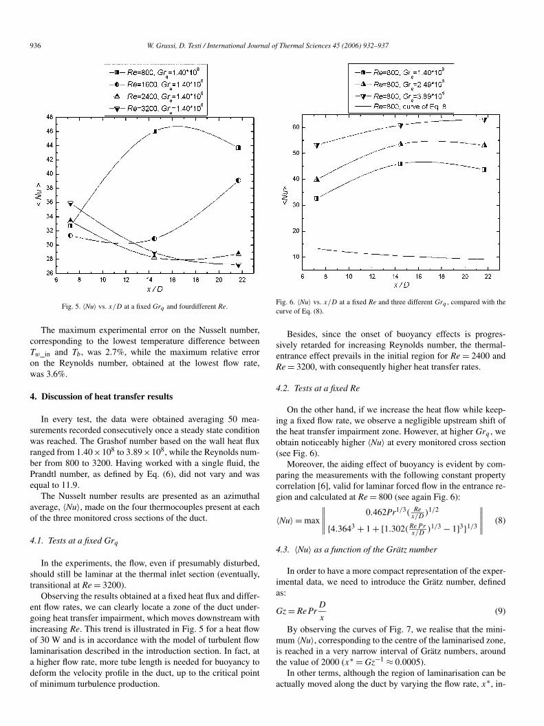
Fig. 5. 〈Nu〉 vs. x/D at a fixed Grq and fourdifferent Re.
The maximum experimental error on the Nusselt number,corresponding to the lowest temperature difference betweenTw_in and Tb , was 2.7%, while the maximum relative erroron the Reynolds number, obtained at the lowest flow rate,was 3.6%.
4. Discussion of heat transfer results
In every test, the data were obtained averaging 50 mea-surements recorded consecutively once a steady state conditionwas reached. The Grashof number based on the wall heat fluxranged from 1.40×10⁸ to 3.89×10⁸, while the Reynolds num-ber from 800 to 3200. Having worked with a single fluid, thePrandtl number, as defined by Eq. (6), did not vary and wasequal to 11.9.
The Nusselt number results are presented as an azimuthalaverage, 〈Nu〉, made on the four thermocouples present at eachof the three monitored cross sections of the duct.
4.1. Tests at a fixed Grq
In the experiments, the flow, even if presumably disturbed,should still be laminar at the thermal inlet section (eventually,transitional at Re = 3200).
Observing the results obtained at a fixed heat flux and differ-ent flow rates, we can clearly locate a zone of the duct under-going heat transfer impairment, which moves downstream withincreasing Re. This trend is illustrated in Fig. 5 for a heat flowof 30 W and is in accordance with the model of turbulent flowlaminarisation described in the introduction section. In fact, ata higher flow rate, more tube length is needed for buoyancy todeform the velocity profile in the duct, up to the critical pointof minimum turbulence production.
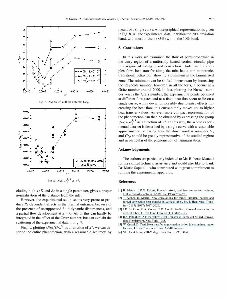
Fig. 6. 〈Nu〉 vs. x/D at a fixed Re and three different Grq , compared with thecurve of Eq. (8).
Besides, since the onset of buoyancy effects is progres-sively retarded for increasing Reynolds number, the thermal-entrance effect prevails in the initial region for Re = 2400 andRe = 3200, with consequently higher heat transfer rates.
4.2. Tests at a fixed Re
On the other hand, if we increase the heat flow while keep-ing a fixed flow rate, we observe a negligible upstream shift ofthe heat transfer impairment zone. However, at higher Grq , weobtain noticeably higher 〈Nu〉 at every monitored cross section(see Fig. 6).
Moreover, the aiding effect of buoyancy is evident by com-paring the measurements with the following constant propertycorrelation [6], valid for laminar forced flow in the entrance re-gion and calculated at Re = 800 (see again Fig. 6):
〈Nu〉 = max
∥∥∥∥∥0.462Pr1/3( Re
x/D)1/2
{4.3643 + 1 + [1.302(RePrx/D
)1/3 − 1]3}1/3
∥∥∥∥∥ (8)
4.3. 〈Nu〉 as a function of the Grätz number
In order to have a more compact representation of the exper-imental data, we need to introduce the Grätz number, definedas:
Gz = Re PrD
x(9)
By observing the curves of Fig. 7, we realise that the mini-mum 〈Nu〉, corresponding to the centre of the laminarised zone,is reached in a very narrow interval of Grätz numbers, aroundthe value of 2000 (x∗ = Gz−1 ≈ 0.0005).
In other terms, although the region of laminarisation can beactually moved along the duct by varying the flow rate, x∗, in-
W. Grassi, D. Testi / International Journal of Thermal Sciences 45 (2006) 932–937 937
Fig. 7. 〈Nu〉 vs. x∗ at three different Grq .
Fig. 8. 〈Nu〉/Gr1/3q vs. x∗.
cluding both x/D and Re in a single parameter, gives a propernormalisation of the distance from the inlet.
However, the experimental setup seems very prone to pro-duce Re-dependent effects in the thermal entrance, because ofthe presence of unsuppressed fluid-dynamic disturbances, anda partial flow development at x = 0. All of this can hardly beintegrated in the effect of the Grätz number, but can explain thescattering of the experimental data in Fig. 7.
Finally, plotting 〈Nu〉/Gr1/3q as a function of x∗, we can de-
scribe the entire phenomenon, with a reasonable accuracy, by
means of a single curve, whose graphical representation is givenin Fig. 8. All the experimental data lie within the 20% deviationband, with most of them (83%) within the 10% band.
5. Conclusions
In this work we examined the flow of perfluorohexane inthe entry region of a uniformly heated vertical circular pipein a regime of aiding mixed convection. Under such a com-plex flow, heat transfer along the tube has a non-monotonic,transitional behaviour, showing a minimum in the laminarised
zone. The minimum can be shifted downstream by increasingthe Reynolds number; however, in all the tests, it occurs at aGrätz number around 2000. In fact, plotting the Nusselt num-ber versus the Grätz number, the experimental points obtainedat different flow rates and at a fixed heat flux seem to lie on asingle curve, with a deviation possibly due to entry effects. In-creasing the heat flow, this curve simply moves up, to higherheat transfer values. An even more compact representation ofthe phenomenon can then be obtained by expressing the group〈Nu〉/Gr1/3
q as a function of x∗. In this way, the whole experi-mental data set is described by a single curve with a reasonableapproximation, stressing how the dimensionless numbers Gzand Grq should be greatly representative of the studied regimeand in particular of the phenomenon of laminarisation.
Acknowledgements
The authors are particularly indebted to Mr. Roberto Manettifor his skillful technical assistance and would also like to thankDr. Mario Saputelli, who contributed with great commitment torunning the experimental apparatus.
References
[1] B. Metais, E.R.G. Eckert, Forced, mixed, and free convection regimes,J. Heat Transfer – Trans. ASME 86 (1964) 295–296.
[2] T. Aicher, H. Martin, New correlations for mixed turbulent natural andforced convection heat transfer in vertical tubes, Int. J. Heat Mass Trans-fer 40 (15) (1997) 3617–3626.
[3] J.D. Jackson, M.A. Cotton, B.P. Axcell, Studies of mixed convection invertical tubes, J. Heat Fluid Flow 10 (1) (1989) 2–15.
[4] B.S. Petukhov, A.F. Polyakov, Heat Transfer in Turbulent Mixed Convec-tion, Hemisphere, New York, 1988.
[5] W. Grassi, D. Testi, Heat transfer augmentation by ion injection in an annu-lar duct, J. Heat Transfer – Trans. ASME, in press.
[6] VDI Heat Atlas, VDI-Verlag, Düsseldorf, 1993, Gb 4.
Copyright © 2022 FDOKUMEN