Numerical investigation of the ion temperature effects on magnetized DC plasma sheath
8
Numerical investigation of the ion temperature effects on magnetized DC plasma sheath Mansour Khoramabadi, 1 Hamid Ghomi, 2,a) and Padma Kant Shukla 3 1 Department of Physics, Boroujerd Branch, Islamic Azad University, Boroujerd, Iran 2 Laser and Plasma Research Institute, Shahid Beheshti University, Evin 1983963113, Tehran, Iran 3 Institut fu ¨ r Theoretische Physik, Fakulta ¨ t fur Physik und Astronomie, Ruhr-Universita ¨ t Bochum, D-44780 Bochum, Germany (Received 18 October 2010; accepted 24 February 2011; published online 6 April 2011) The properties of a magnetized plasma sheath with finite ion temperature is considered. The effects of the external magnetic field and the ion temperature on the sheath parameters are examined. It is found that by increasing the ion temperature and the magnetic field strength there is an increase in the positive space charge and the ion energy and a decrease in the sheath thickness. Furthermore, the ion temperature has a direct effect on the ion flux toward the wall. V C 2011 American Institute of Physics. [doi:10.1063/1.3569844] I. INTRODUCTION The subject of interactions between the plasma and a solid wall and the formation of a boundary layer around it is almost as old as plasma physics itself. The problem of a magnetized plasma boundary has a particular importance in material processing by the plasma and the plasma confine- ment in magnetic fusion devices. The importance of the plasma boundary layer in an external magnetic field has drawn much attention in recent years. Nonetheless, the physics of the plasma boundary is still not perfectly under- stood. In a simple model, a confined plasma is brought into contact with a conducting wall. Since the mobility of the electrons is much higher than that of the ions, the wall is bombarded by the background electrons and attains a nega- tive potential with respective to the bulk of the plasma. The negative potential around the plasma attracts the ions toward the wall and repels the electrons toward the plasma. In the steady state, a positive space charge forms near the wall to balance the flow of the ions and electrons into the wall. The plasma boundary layer is thus divided into two separate regions: a neutral presheath adjacent to the plasma and a pos- itive charged sheath adjacent to the wall. The sheath width is usually a few Debye radius and its task is to shield the plasma from the wall, while the presheath width is deter- mined by the size of the plasma container or by the ion mean free path 1 and its function is to fulfill the well known Bohm criterion. The latter is needed in order to adjust the positive space charge associated with the ions that are entering into the sheath. 2,3 Usually, the sheath is collisionless and planar and its width is small in comparison with the presheath. Since the sheath and presheath regions have different charac- teristics and functions, it is obvious to use different scales in studying the plasma boundary layer. According to the two- scales theory, the sheath region is scaled by the electron Debye radius, while the presheath is scaled by the size of the plasma. Thus, we can solve the plasma boundary problem in these two-scales separately. On the sheath scale the pre- sheath is infinitely far from the wall where the electric field is zero. On the presheath scale, the sheath is infinitesimally thin and the electric there field is infinite. As can be seen the sheath-presheath interface, the so- called sheath edge, has an ambiguous behavior and one has to remove the contradicting behavior while solving the matching problem. 4–7 Riemann, 8 Franklin, 9 and Zimmermann et al. 10 investigated the effect of collisions on the boundary layer of a magnetized plasma on the presheath scale. They deduced that the magnetic field along with collisions do not modify the Bohm criterion for the sheath formation. On the basis of this issue, several works investigated the plasma boundary layer on the sheath scale by using the same Bohm criterion as in the unmagne- tized plasma. 11–14 In our previous work, we obtained a gen- eralized Bohm criterion in a collisional plasma with the ion temperature effect on the sheath scale. 15 Recently, it has been shown that the ion temperature strongly affects the sheath properties (such as the ion energy and the density). Emmert et al. 16 presented a formalism for the ion thermal effect on the electrostatic potential in the bulk of the plasma and in the sheath near an adsorbing plane wall. They obtained an integrodifferential equation for the potential in both the plasma and sheath regions and numerically solved it. They concluded that an increase of the ion temperature leads to a slow increase of the sheath width and to a decrease of the potential at the sheath edge. Here, in a sequel to the earlier works by Minghao et al., 17 and on the basis of the two-fluid model, the characteristics of a magnetized DC plasma sheath are numerically investigated and the effect of the ion temperature on the sheath properties is examined. Specifically, our study is concerned with the effects of a con- stant magnetic field and the ion temperature on the sheath behavior. In order to understand the main physical features determining the stationary sheath, the analysis has been re- stricted to the charged boundary layer (sheath scale), and processes in the bulk of the plasma and presheath are not considered. In Sec. I, nonlinear equations in a simple plasma sheath model are formulated. In Sec. III, numerical results and the corresponding discussions are presented, displaying a) Author to whom correspondence should be addressed. Electronic mail: [email protected]. 0021-8979/2011/109(7)/073307/8/$30.00 V C 2011 American Institute of Physics 109, 073307-1 JOURNAL OF APPLIED PHYSICS 109, 073307 (2011) Downloaded 10 Apr 2011 to 217.218.83.61. Redistribution subject to AIP license or copyright; see http://jap.aip.org/about/rights_and_permissions
Transcript of Numerical investigation of the ion temperature effects on magnetized DC plasma sheath

Numerical investigation of the ion temperature effects on magnetized DCplasma sheath
Mansour Khoramabadi,1 Hamid Ghomi,2,a) and Padma Kant Shukla3
1Department of Physics, Boroujerd Branch, Islamic Azad University, Boroujerd, Iran2Laser and Plasma Research Institute, Shahid Beheshti University, Evin 1983963113, Tehran, Iran3Institut fur Theoretische Physik, Fakultat fur Physik und Astronomie, Ruhr-Universitat Bochum, D-44780Bochum, Germany
(Received 18 October 2010; accepted 24 February 2011; published online 6 April 2011)
The properties of a magnetized plasma sheath with finite ion temperature is considered. The effects
of the external magnetic field and the ion temperature on the sheath parameters are examined. It is
found that by increasing the ion temperature and the magnetic field strength there is an increase in
the positive space charge and the ion energy and a decrease in the sheath thickness. Furthermore,
the ion temperature has a direct effect on the ion flux toward the wall. VC 2011 American Institute ofPhysics. [doi:10.1063/1.3569844]
I. INTRODUCTION
The subject of interactions between the plasma and a
solid wall and the formation of a boundary layer around it is
almost as old as plasma physics itself. The problem of a
magnetized plasma boundary has a particular importance in
material processing by the plasma and the plasma confine-
ment in magnetic fusion devices. The importance of the
plasma boundary layer in an external magnetic field has
drawn much attention in recent years. Nonetheless, the
physics of the plasma boundary is still not perfectly under-
stood. In a simple model, a confined plasma is brought into
contact with a conducting wall. Since the mobility of the
electrons is much higher than that of the ions, the wall is
bombarded by the background electrons and attains a nega-
tive potential with respective to the bulk of the plasma. The
negative potential around the plasma attracts the ions toward
the wall and repels the electrons toward the plasma. In the
steady state, a positive space charge forms near the wall to
balance the flow of the ions and electrons into the wall. The
plasma boundary layer is thus divided into two separate
regions: a neutral presheath adjacent to the plasma and a pos-
itive charged sheath adjacent to the wall. The sheath width is
usually a few Debye radius and its task is to shield the
plasma from the wall, while the presheath width is deter-
mined by the size of the plasma container or by the ion mean
free path1 and its function is to fulfill the well known Bohm
criterion. The latter is needed in order to adjust the positive
space charge associated with the ions that are entering into
the sheath.2,3 Usually, the sheath is collisionless and planar
and its width is small in comparison with the presheath.
Since the sheath and presheath regions have different charac-
teristics and functions, it is obvious to use different scales in
studying the plasma boundary layer. According to the two-
scales theory, the sheath region is scaled by the electron
Debye radius, while the presheath is scaled by the size of the
plasma. Thus, we can solve the plasma boundary problem in
these two-scales separately. On the sheath scale the pre-
sheath is infinitely far from the wall where the electric field
is zero. On the presheath scale, the sheath is infinitesimally
thin and the electric there field is infinite. As can be seen the
sheath-presheath interface, the so- called sheath edge, has an
ambiguous behavior and one has to remove the contradicting
behavior while solving the matching problem.4–7 Riemann,8
Franklin,9 and Zimmermann et al.10 investigated the effect
of collisions on the boundary layer of a magnetized plasma
on the presheath scale. They deduced that the magnetic field
along with collisions do not modify the Bohm criterion for
the sheath formation. On the basis of this issue, several
works investigated the plasma boundary layer on the sheath
scale by using the same Bohm criterion as in the unmagne-
tized plasma.11–14 In our previous work, we obtained a gen-
eralized Bohm criterion in a collisional plasma with the ion
temperature effect on the sheath scale.15 Recently, it has
been shown that the ion temperature strongly affects the
sheath properties (such as the ion energy and the density).
Emmert et al.16 presented a formalism for the ion thermal
effect on the electrostatic potential in the bulk of the plasma
and in the sheath near an adsorbing plane wall. They
obtained an integrodifferential equation for the potential in
both the plasma and sheath regions and numerically solved
it. They concluded that an increase of the ion temperature
leads to a slow increase of the sheath width and to a decrease
of the potential at the sheath edge. Here, in a sequel to the
earlier works by Minghao et al.,17 and on the basis of the
two-fluid model, the characteristics of a magnetized DC
plasma sheath are numerically investigated and the effect of
the ion temperature on the sheath properties is examined.
Specifically, our study is concerned with the effects of a con-
stant magnetic field and the ion temperature on the sheath
behavior. In order to understand the main physical features
determining the stationary sheath, the analysis has been re-
stricted to the charged boundary layer (sheath scale), and
processes in the bulk of the plasma and presheath are not
considered. In Sec. I, nonlinear equations in a simple plasma
sheath model are formulated. In Sec. III, numerical results
and the corresponding discussions are presented, displaying
a)Author to whom correspondence should be addressed. Electronic mail:
0021-8979/2011/109(7)/073307/8/$30.00 VC 2011 American Institute of Physics109, 073307-1
JOURNAL OF APPLIED PHYSICS 109, 073307 (2011)
Downloaded 10 Apr 2011 to 217.218.83.61. Redistribution subject to AIP license or copyright; see http://jap.aip.org/about/rights_and_permissions
the role of the magnetic field in the formation of the thermal
sheath. Section IV contains a brief summary and conclusions.
II. MODEL AND BASIC EQUATIONS
Here we introduce a magnetized plasma sheath with the
finite ion temperature to examine its properties in the steady
state. If a planar target with a large negative potential is
immersed in this plasma, a planar (one-dimensional) sheath
(dark space) is formed around it. We choose the x-axis nor-
mal to the target surface, and the position of the plasma-
sheath interface at x ¼ 0. In x < 0, there is a quasineutral
plasma with u � 0. The plasma is composed of electrons
and singly charged ions, which are considered as fluids. In
the region x > 0, there is a non-neutral sheath. Indeed, it is
assumed that the ions, which are generated in the bulk of the
plasma (x < 0), are accelerated in a presheath by a weak
electric field toward the sheath, and enter into the sheath
with a nonzero velocity (the Bohm criterion). In the steady
state (@=@t ¼ 0), for a collisionless sheath, the ion fluid
equations are
r � ðniviÞ ¼ 0; (1)
minivi � rvi ¼ eniðEþ vi � BÞ � rpi; (2)
where vi is the average ion flow velocity, e is the magnitude
of the electron charge, E ¼ �ru (with u as the electrostatic
potential), and B defines the electric and magnetic fields,
respectively; mi and ni are the ion mass and the ion number
density, respectively. These equations are identical with
those in Ref. 12. Assuming ion isothermal flow, the ion pres-
sure pi is
pi ¼ kBTini; (3)
where kB is the Boltzmann constant and Ti is the ion temper-
ature. The electrons are in thermal equilibrium and obey the
Boltzmann density distribution
ne ¼ ne0 expeu
kBTe
� �; (4)
where ne0 denotes the electron number density at the sheath
edge and Te is the electron temperature. Finally, by using
Poisson’s equation, which relates the electron and ion num-
ber densities to the electric potential
r2u ¼ � e
e0
ðni � neÞ; (5)
we can close our governing equations. It is assumed that the
ion-neutral collisions indirectly allow the ions to behave like
an isothermal warm fluid. Since there are no variations in the
sheath parameters along the direction parallel to the wall and
the spatial variations are only in the normal to wall direction,
we then consider the geometry of the problem in one-space
dimension and assume that r ! xd=dx. Therefore, from
Eqs. (1) and (5) we have
nitix ¼ ni0tix0 (6)
d2/dx2¼ � e
e0
ðni � neÞ (7)
with ni0 and tix0 as the ion number density and the x-compo-
nent of the average ion velocity at the sheath edge. Accord-
ing to the general criterion for the stationary sheath
formation in the fluid approximation,1,10,15 the isothermal
ions have to enter the sheath region with the normal to wall
initial velocity defined by
tix0 ¼
ffiffiffiffiffiffiffiffiffiffiffiffiffiffiffiffiffiffiffiffiffiffiffiffiffiffiffiffiffiffikBTe
mi1þ Ti
Te
� �s� cs: (8)
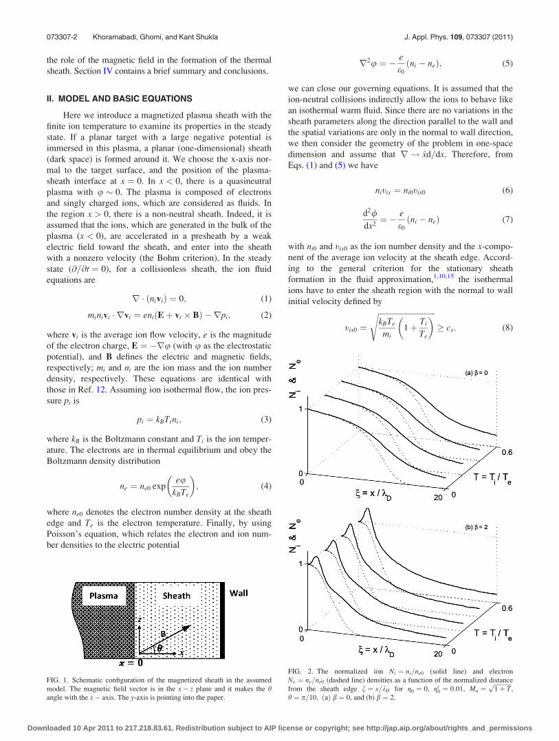
FIG. 1. Schematic configuration of the magnetized sheath in the assumed
model. The magnetic field vector is in the x� z plane and it makes the hangle with the x� axis. The y-axis is pointing into the paper.
FIG. 2. The normalized ion Ni ¼ ni=ne0 (solid line) and electron
Ne ¼ ne=ne0 (dashed line) densities as a function of the normalized distance
from the sheath edge n ¼ x=kD for g0 ¼ 0, g00 ¼ 0:01, Ma ¼ffiffiffiffiffiffiffiffiffiffiffiffi1þ Tp
,
h ¼ p=10; ðaÞ b ¼ 0, and (b) b ¼ 2.
073307-2 Khoramabadi, Ghomi, and Kant Shukla J. Appl. Phys. 109, 073307 (2011)
Downloaded 10 Apr 2011 to 217.218.83.61. Redistribution subject to AIP license or copyright; see http://jap.aip.org/about/rights_and_permissions
Conversely, referring to the geometry sketched in Fig. 1 and
assuming that B ¼ B0ðx cos hþ z sin hÞ, one can obtain from
Eq. (2)
tixdvix
dx¼ � e
mi
d/dxþ eB0
mitiy sin h� kBTi
mi
1
ni
dni
dx; (9)
tixdtiy
dx¼ eB0
miðtiz cos h� tix sin hÞ; (10)
tixdtiz
dx¼ � eB0
mitiy cos h: (11)
For convenience, we introduce the dimensionless variables,
Ni ¼ ni=ne0, Ne ¼ ne=ne0, T ¼ Ti=Te, n ¼ x=kD, qi ¼ css,
xc ¼ eB0=mi ¼ 1=s, uj ¼ tij=cs ðj ¼ x; y; and zÞ,kD ¼
ffiffiffiffiffiffiffiffiffiffiffiffiffiffiffiffiffiffiffiffiffiffiffiffiffie0kBTe=ne0e2
p, b ¼ kD=qi ¼
ffiffiffiffiffiffiffiffiffiffiffiffiffiffiffiffiffie0=mine0
pB0, cs
¼ffiffiffiffiffiffiffiffiffiffiffiffiffiffiffiffikBTe=mi
p, g ¼ �eu=kBTe. Hence, with Eqs. (4) and (6)–
(11), together with the charge neutrality condition in the
sheath edge ne0 ¼ ni0, we have
Ni ¼Ma
ux; (12)
Ne ¼ expð�gÞ; (13)
ux0 ¼dux
dn¼ ux
u2x � T
dgdnþ buy sin h
� �; (14)
uy0 ¼duy
dn¼ b
uz
uxcos h� sin h
� �; (15)
uz0 ¼duz
dn¼ �b
uy
uxcos h; (16)
g00 ¼ d2g
dn2¼ Ni � Ne; (17)
where cs is the ion-acoustic velocity, Ma ¼ tix0=cs is the ion
Mach number, kD is the electron Debye length at the sheath
edge, s is the ion gyroperiod, qi is the ion gyroradius, and nis the distance from the sheath edge normalized by kD. b is
the parameter that indicates the magnetic field magnitude.
III. NUMERICAL RESULTS AND DISCUSSION
To solve the equations of the ion motion and Poisson’s
equation, we use gð0Þ ¼ 0, g0ð0Þ ¼ 0:01, uxð0Þ ¼ Ma
¼ffiffiffiffiffiffiffiffiffiffiffiffi1þ Tp
, uyð0Þ ¼ uzð0Þ ¼ 0, and Nið0Þ ¼ Neð0Þ ¼ 1 as
boundary conditions at the plasma-sheath interface (n ¼ 0).
As shown, the Bohm velocity at the sheath edge is a function
of T,8–10,15 and is independent of B in weak magnetic fields.
To examine the sheath structure, it is appropriate to investi-
gate the profiles of the particle density, the electric potential,
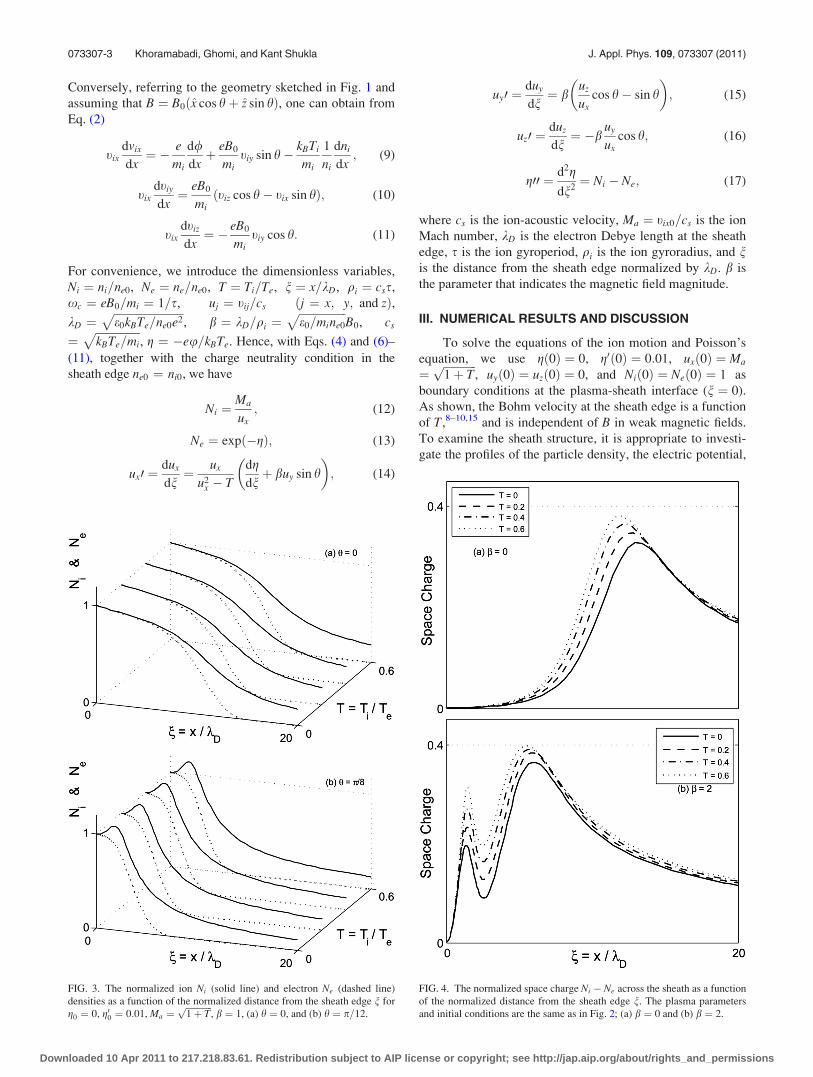
FIG. 3. The normalized ion Ni (solid line) and electron Ne (dashed line)
densities as a function of the normalized distance from the sheath edge n for
g0 ¼ 0, g00 ¼ 0:01, Ma ¼ffiffiffiffiffiffiffiffiffiffiffiffi1þ Tp
, b ¼ 1, (a) h ¼ 0, and (b) h ¼ p=12.
FIG. 4. The normalized space charge Ni � Ne across the sheath as a function
of the normalized distance from the sheath edge n. The plasma parameters
and initial conditions are the same as in Fig. 2; (a) b ¼ 0 and (b) b ¼ 2.
073307-3 Khoramabadi, Ghomi, and Kant Shukla J. Appl. Phys. 109, 073307 (2011)
Downloaded 10 Apr 2011 to 217.218.83.61. Redistribution subject to AIP license or copyright; see http://jap.aip.org/about/rights_and_permissions

and the ion velocity. For this purpose, by using a Runge-
Kutta method of the fourth-order, Eqs. (12)–(17) are solved
and the numerical results are discussed in the next
subsections.
A. Ion temperature effect on particle density
The numerical solutions of Eqs. (12)–(17) are displayed
in Figs. 2–11. In Figs. 2 and 3 the spatial variations of the
normalized ion and electron densities have been illustrated
for different values of b (b ¼ 0; 2), h (h ¼ 0; p=12), and TðT ¼ 0; 0:2; 0:4; and 0:6Þ across the sheath. These figures
exhibit that increasing the magnitude of an oblique magnetic
field ðbÞ for constant h (Fig. 2), or increasing the magnetic
field angle with the normal to the wall ðhÞ for constant b(Fig. 3), increases the aggregation of both kinds of particles
near the sheath edge and increasing the ion temperature
slightly intensifies this effect. All electron densities (dashed
line) decrease smoothly according to the Boltzmann relation.
The ion distribution, however, strongly depends upon the
magnetic field strength and for a critical value it begins to
fluctuate, but the sheath formation condition ðNi � NeÞ is
compliant across the sheath. Also the spatial variations of the
difference between the ion and electron densities are
depicted in Figs. 4 and 5. From these figures, we see that
ðNi � NeÞ � 0 across the sheath and a positive space charge
is formed near the wall. According to these figures, it is evi-
dent that an increase in b and h values gives rise to an
enhancement of the fluctuation rate of the positive space
charge and shifts the location of the charge accumulation to
the sheath edge. Both Figs. 4 and 5 exhibit that an increase
in the ion temperature leads to a growth of the positive space
charge and a transmission of the positive space charge to-
ward the sheath edge. From Figs. 4 and 5 we see that there is
no difference between the space charge profile in the absence
of a magnetic field b ¼ 0 and the space charge profile in the
presence of a normal to wall magnetic field ðh ¼ 0Þ. We con-
clude that only the transverse component of the magnetic
field ðbT ¼ b sin hÞ plays the original role and the normal to
wall magnetic field component ðbN ¼ b cos hÞ does not have
any influence on the spatial variation of the sheath
parameters.
B. Electric potential and ion velocity
From the ion continuity equation we know that the xcomponent of the ion velocity is inversely proportional to
FIG. 5. The normalized space charge Ni � Ne across the sheath as a function
of the distance from the sheath edge n. The plasma parameters and initial
conditions are the same as in Fig. 3; (a) h ¼ 0 and (b) h ¼ p=12.
FIG. 6. The normalized x-component of the ion velocity ux ¼ vix=cs across
the sheath as a function of the distance from the sheath edge n. The plasma
parameters and initial conditions are the same as in Fig. 2; (a) b ¼ 0 and
(b) b ¼ 2.
073307-4 Khoramabadi, Ghomi, and Kant Shukla J. Appl. Phys. 109, 073307 (2011)
Downloaded 10 Apr 2011 to 217.218.83.61. Redistribution subject to AIP license or copyright; see http://jap.aip.org/about/rights_and_permissions

the ion density. Therefore, From Figs. 2 and 3, we expect
that ux increases across the sheath and oscillates with an
increase in the transverse component of the magnetic field
ðbTÞ. In Fig. 6, the spatial variations of the x component of
the normalized ion velocity is shown for different values of
bðb ¼ 0; 0:2Þ and TðT ¼ 0; 0:2; 0:4; and 0:6Þ across the
sheath. The x component of the initial velocity of the ions is
a function of T (according to the boundary conditions). From
Poisson’s equation it is well known that the space charge cre-
ates the electric field. The positive space charge in the sheath
region creates an electric field toward the wall, which is
associated with a decreasing electric potential (increasing
normalized electric potential) from the sheath edge toward
the wall. According to Figs. 4 and 5, an increase in bT or Tgives rise to an increase in the space charge and shifts it to-
ward the sheath edge. Thus, both effects increase the normal-
ized electric potential ðgÞ across the sheath. Figure 7
apparently displays the increase of the normalized electric
potential with the increase of b (or h) or T. It shows that the
sheath width (the distance between the sheath edge and the
wall with a constant electric potential) descends with an
increase in the ion temperature or the transverse component
of the magnetic field in a constant wall potential. Note that
the wall location is characterized by its electric potential.
From this figure, it is clear that in contrast with the space
charge distribution, there is no fluctuation in the electric
potential distribution. Indeed, the fluctuation on the space
charge distribution results in the fluctuation in the electric
field and then in the x-component of the ion velocity distri-
bution. Alternatively, on the basis of the energy conservation
law, the electric potential energy of the ions in the sheath is
equal totheir kinetic energy (the ion speed) in the absence of
collisions. So the electric potential and the ion speed distri-
butions across the sheath are proportional to each other.
Figure 8 illustrates the ion speed distribution u (magnitude
of the ion velocity) across the sheath for different values of band T. As expected, the distribution of the ion speed and the
electric potential are smoothly increasing functions. Accord-
ing to Figs. 2–8, the presence of an oblique magnetic field
strongly affects the ion dynamics in a collisionless magne-
tized sheath. Indeed the transverse component (parallel to
the wall) of the magnetic field allows the ions to gyrate and
FIG. 7. The normalized electric potential g ¼ �eu=kBTe across
the sheath as a function of the distance from the sheath edge n.
The plasma parameters and initial conditions are the same as in
Fig. 2; (a) b ¼ 0 and (b) b ¼ 2.
073307-5 Khoramabadi, Ghomi, and Kant Shukla J. Appl. Phys. 109, 073307 (2011)
Downloaded 10 Apr 2011 to 217.218.83.61. Redistribution subject to AIP license or copyright; see http://jap.aip.org/about/rights_and_permissions

consequently, the ion density and all components of the ion
velocity fluctuate.
C. Wall net current
In the sheath region, there is an increasing normalized
electric potential, a decreasing electron number density
according to the Boltzmann relation, along with a descend-
ing electron current to the wall. One can then define the net
current to the wall as
jn ¼ ji � je ¼ evixni �1
4ecene; (18)
where ce ¼ ð8kBTe=pmeÞ1=2is the electron thermal speed
and me the electron mass. Normalizing the net current by
j0 ¼ ene0cs one obtains from Eq. (18)
Jn ¼ Ji � Je ¼ uxNi �mi
2pme
� �1=2
Ne: (19)
Figure 9 displays the normalized net current of the wall
across the sheath for mi ¼ 40mH (considering argon atoms as
ionized gas) with mH as the hydrogen atom mass. This figure
shows that by increasing the wall electric potential and wid-
ening the sheath width, the net current to the wall rises from
a large negative value in the sheath edge and is saturated to a
positive value. Additionally, in this figure the characteristic
curve, I � V, has been illustrated on a smaller scale to clarify
the saturation current and floating potential (a wall electric
potential in which the wall net current becomes zero). From
Fig. 9 it is apparent that increasing the transverse component
of the magnetic field decreases the sheath width in the float-
ing potential and it does not have any effect on the floating
potential and saturation net current. We deduce from this fig-
ure that increasing the ion temperature decreases the floating
potential and raises the saturation net current to the wall.
D. Transverse drift of ions
In contrast to the presheath,9 in the sheath both the mag-
netic and electric forces play an important role. Figures 6
and 8 show that the ion speed ðuÞ is a smoothly increasing
function despite the fact that the x� component of the
FIG. 8. The normalized ion speed u ¼ffiffiffiffiffiffiffiffiffiffiffiffiffiffiffiffiffiffiffiffiffiffiffiffiffiu2
x þ u2y þ u2
z
qacross the sheath as a
function of the distance from the sheath edge n. The plasma parameters and
initial conditions are the same as in Fig. 2; (a) b ¼ 0 and (b) b ¼ 2.
FIG. 9. The normalized net current of the wall across the sheath as a func-
tion of the distance from the sheath edge n. The plasma parameters and ini-
tial conditions are the same as in Fig. 2; (a) b ¼ 0 and (b) b ¼ 2.
073307-6 Khoramabadi, Ghomi, and Kant Shukla J. Appl. Phys. 109, 073307 (2011)
Downloaded 10 Apr 2011 to 217.218.83.61. Redistribution subject to AIP license or copyright; see http://jap.aip.org/about/rights_and_permissions

ion velocity fluctuates across the sheath. It means that the
y� and z� components of the ion velocity have to fluctuate
as well. Indeed, the transverse component of the ion velocity
ðuT ¼ffiffiffiffiffiffiffiffiffiffiffiffiffiffiffiu2
y þ u2z
qÞ fluctuates inversely with its longitudinal
component ðuxÞ. The z� component of the ion velocity is
shown in Fig. 10 as a function of ux for different values of hand T. This figure is of particular significance, since it shows
the net direction of the ion motion in the x� z plane. This
direction is close to the magnetic field direction, but the tur-
bulent motion of the ion fluid has another drifting motion
along the E� B direction. The y�component of the ion ve-
locity as a function of ux has been plotted in Fig. 11, showing
the net direction of the ion motion in the x� y plane. The
motion of the ions along the y axis is the well-known drifting
motion of E� B in the plasma and increases with the
increase of h (the angle between E and B). Figures 10 and 11
show that an increase in the ion temperature only increases
the longitudinal component of the ion velocity and does not
have any effect on its transverse component. It is clear from
these figures that the ion temperature, in contrast to the trans-
verse component of the magnetic field, increases the ion lon-
gitudinal motion (normal to the wall).
IV. SUMMARY AND CONCLUSION
In this paper, we have presented a general description of
a magnetized plasma sheath composed of warm positive ions
and Boltzmann distributed inertia-less electrons. Based on
the two-fluid model, the ion and electron densities, the ion
velocity, the wall net current, and the electric potential have
been investigated across the sheath for different values of the
ion temperature and the transverse component of the mag-
netic field. It is found that the normal component of the mag-
netic field does not have any effect on the sheath parameters.
However, the transverse component of the magnetic field
causes the positive charge accumulation toward the sheath
edge and the ion temperature further enhances this effect. It
is found that by increasing the ion temperature and the
strength of the oblique magnetic field in the sheath, the posi-
tive space charge increases. Accordingly, the ion tempera-
ture and the transverse component of the magnetic field
decrease the sheath width. Furthermore, our numerical
results reveal that the higher plasma temperature increases
the net current to the wall. We note that the external oblique
magnetic field does not have any effect on the wall saturation
current and the floating potential. Moreover, the magnetic
FIG. 10. The normalized z component of the ion velocity uz as a function of
the normalized x-component of the ion velocity ux. The plasma parameters
and initial conditions are the same as in Fig. 3; (a) h ¼ p=12 and
(b) h ¼ p=8.
FIG. 11. The normalized y component of the ion velocity uy as a function of
the normalized x component of the ion velocity ux. The plasma parameters
and initial conditions at the sheath edge are the same as in Fig. 3;
(a) h ¼ p=12 and (b) h ¼ p=8.
073307-7 Khoramabadi, Ghomi, and Kant Shukla J. Appl. Phys. 109, 073307 (2011)
Downloaded 10 Apr 2011 to 217.218.83.61. Redistribution subject to AIP license or copyright; see http://jap.aip.org/about/rights_and_permissions
field increases the transverse drifting motion of the ions and
the ion temperature enhances their longitudinal drifting
motion. The present results have applications in plasma proc-
essing; for example, in ion implantation using magnetized
electropositive plasmas. Specifically, we note that an
increase of the ion temperature would increase the penetra-
tion depth into the target by increasing the ion’s energy and
their longitudinal velocity. Also, in magnetron sputtering,
the ion temperature increases the rate of the coating by rais-
ing the ion flux to the target.
1K. U. Riemann, J. Phys. D: Appl. Phys. 24, 493 (1991).2L. Tonks and I. Langmuir, Phys. Rev. 34, 876 (1929).3D. Bohm, Characteristics of Electrical Discharges in Magnetic Fields(McGraw-Hill, New York, 1949).
4K. U. Riemann, Phys. Plasmas 4, 4158 (1997).
5K. U. Riemann, Plasma Phys. Controlled Fusion 47, 1949 (2005).6R. N. Franklin, J. Phys. D: Appl. Phys. 31, 2532 (1998).7R. N. Franklin, J. Phys. D: Appl. Phys. 36, R309 (2003).8K. U. Riemann, Phys. Plasmas 1, 552 (1994).9R. N. Franklin, J. Phys. D: Appl. Phys. 38, 3412 (2005).
10T. M. G. Zimmermann, M. Coppins, and J. E. Allen, Phys. Plasmas 15,
072301 (2008).11S. F. Masoudi, J. Phys. D: Appl. Phys. 40, 6641 (2007).12Z. Xiu, L. Y. Jin, G. Ye, W. X. Zheng, L. Yue., and W. G. Xiao, Vacuum
73, 681 (2004).13K. Yasserian, M Aslaninejad, M. Ghoranneviss, and F. M. Aghamir,
J. Phys. D: Appl. Phys. 41, 105215 (7pp) (2008).14M. M. Hatami, B. Shokri, and A. R. Niknam, J. Phys. D: Appl. Phys. 42,
025204 (2009).15H. Ghomi, and M. Khoramabadi, J Plasma Phys. 76, 247 (2010).16G. A. Emmert, R. M. Wieland, A. T. Mense, and J. N. Davidson, Phys.
Fluids 23, 803 (1980).17L. Minghao, Z. Yu, D. Wanyu, L. Jinyuan, and W. Xiaogang, Plasma Sci.
Technol. 8, 544 (2006).
073307-8 Khoramabadi, Ghomi, and Kant Shukla J. Appl. Phys. 109, 073307 (2011)
Downloaded 10 Apr 2011 to 217.218.83.61. Redistribution subject to AIP license or copyright; see http://jap.aip.org/about/rights_and_permissions