
Coating-Defect Localization of Naval Vessels using the ...
11
IEEE WORKSHOP 2019 Industrial and Medical Measurement and Sensor Technology Vehicle Sensor Technology | June, 6th - 7th 2019, Mülheim an der Ruhr 14 Coating-Defect Localization of Naval Vessels using the onboard Impressed Current Cathodic Protection System Christian Thiel (1) , Kevin Neumann (1) , Claas Broecheler (1) , Andreas Rennings (1) , Frank Ludwar (2) , Jens Doose(2), and Daniel Erni (1) (1) General and Theoretical Electrical Engineering (ATE), Faculty of Engineering, University of Duisburg-Essen, D-47048 Duisburg, Germany (2) Technical Center for Ships and Naval Weapons, Naval Technology and Research (WTD 71), Bundeswehr, D-24340 Eckernförde, Germany E-Mail: [email protected] Web: https://www.ate.uni-due.de Abstract In this work a method for predicting coating damages of naval vessels using only highly aggregated infor- mation provided by the onboard corrosion protection system is presented. The estimation is based on a com- bination of computational electromagnetics (relying on a finite element method (FEM) simulator) and machine learning. The corrosion process of naval vessels mainly occurs due to different metallic materials which are galvanically connected where in presence of the seawater (electrolyte) a current density from the anodic ma- terial to the cathodic material through the seawater will always emerge. This current density field in combina- tion with the electric conductivity of the seawater can alternatively be described as an electric field also known as the so-called underwater electric potential (UEP) signature. The UEP signature is a relevant quantity in marine research especially in the context of signature silencing when using corresponding countermeasures such as e.g. signature minimization and signature management [1]. To prevent the emerging corrosion process, specific protection systems are usually installed on naval ves- sels, which can be classified in active and passive corrosion protection systems. As an example, a vector plot of the electric current density generated by an active corrosion protection system through the seawater is pre- sented in Fig.1 which has been computed using the FEM simulation platform COMSOL Multiphysics [2]. Fig.1: Simulated vector field of the electric current density using the finite element method (FEM) solver COMSOL Multi-physics [1]. The imposed current density points from the corrosion protection system towards the ship’s hull and ensures a protective state of the vessel because it counteracts the ubiquitous electrochemically induced corrosion process. The current density field visualized as streamlines in Fig.1 is pointing from the corrosion protection system (anode) towards the hull to ensure a protective (cathodic) state of the vessel. The active corrosion protection considered here is based on the impressed current cathodic protection (ICCP) system which uses a highly corrosion resistant anode material to actively impress anodic currents while enforcing the ship’s hull in the desired cathodic regime and hence, inhibiting corrosion. Additionally, another active corrosion protection scheme, namely the sacrificial anodic cathodic protection (SACP) system has been implemented on the vessel which is visualized in Fig. 1 as a regular distribution of small circular patches over the hull. The main reason for adding small SACP electrodes (anodes) to the ICCP system is to smoothen the electric potential distribution over the hull yielding a more uniform corrosion pro- tection potential. When a specific value of the electric potential on the underlying material surface is reached, this material can be considered as corrosion protected. The exact values of said protection potentials are regu- lated in corresponding standards. Passive corrosion protection is defined as a non-conducting coating of the vessel’s hull and is also implemented in our numerical analysis. When introducing localized coating damages to the passive protection layer, the
-
Upload
khangminh22 -
Category
Documents
-
view
1 -
download
0
Transcript of Coating-Defect Localization of Naval Vessels using the ...

IEEE WORKSHOP 2019 Industrial and Medical Measurement and Sensor Technology Vehicle Sensor Technology | June, 6th - 7th 2019, Mülheim an der Ruhr
14
Coating-Defect Localization of Naval Vessels using the onboard Impressed Current Cathodic Protection System
Christian Thiel(1), Kevin Neumann(1), Claas Broecheler (1), Andreas Rennings(1), Frank Ludwar(2), Jens Doose(2), and Daniel Erni(1)
(1) General and Theoretical Electrical Engineering (ATE), Faculty of Engineering, University of Duisburg-Essen, D-47048 Duisburg, Germany (2) Technical Center for Ships and Naval Weapons, Naval Technology and Research (WTD 71), Bundeswehr, D-24340 Eckernförde, Germany
E-Mail: [email protected] Web: https://www.ate.uni-due.de Abstract In this work a method for predicting coating damages of naval vessels using only highly aggregated infor-mation provided by the onboard corrosion protection system is presented. The estimation is based on a com-bination of computational electromagnetics (relying on a finite element method (FEM) simulator) and machine learning. The corrosion process of naval vessels mainly occurs due to different metallic materials which are galvanically connected where in presence of the seawater (electrolyte) a current density from the anodic ma-terial to the cathodic material through the seawater will always emerge. This current density field in combina-tion with the electric conductivity of the seawater can alternatively be described as an electric field also known as the so-called underwater electric potential (UEP) signature.
The UEP signature is a relevant quantity in marine research especially in the context of signature silencing when using corresponding countermeasures such as e.g. signature minimization and signature management [1]. To prevent the emerging corrosion process, specific protection systems are usually installed on naval ves-sels, which can be classified in active and passive corrosion protection systems. As an example, a vector plot of the electric current density generated by an active corrosion protection system through the seawater is pre-sented in Fig.1 which has been computed using the FEM simulation platform COMSOL Multiphysics [2].
Fig.1: Simulated vector field of the electric current density using the finite element method (FEM) solver COMSOL Multi-physics [1]. The imposed current density points from the corrosion protection system towards the ship’s hull and ensures a protective state of the vessel because it counteracts the ubiquitous electrochemically induced corrosion process. The current density field visualized as streamlines in Fig.1 is pointing from the corrosion protection system (anode) towards the hull to ensure a protective (cathodic) state of the vessel. The active corrosion protection considered here is based on the impressed current cathodic protection (ICCP) system which uses a highly corrosion resistant anode material to actively impress anodic currents while enforcing the ship’s hull in the desired cathodic regime and hence, inhibiting corrosion.
Additionally, another active corrosion protection scheme, namely the sacrificial anodic cathodic protection (SACP) system has been implemented on the vessel which is visualized in Fig. 1 as a regular distribution of small circular patches over the hull. The main reason for adding small SACP electrodes (anodes) to the ICCP system is to smoothen the electric potential distribution over the hull yielding a more uniform corrosion pro-tection potential. When a specific value of the electric potential on the underlying material surface is reached, this material can be considered as corrosion protected. The exact values of said protection potentials are regu-lated in corresponding standards.
Passive corrosion protection is defined as a non-conducting coating of the vessel’s hull and is also implemented in our numerical analysis. When introducing localized coating damages to the passive protection layer, the

IEEE WORKSHOP 2019 Industrial and Medical Measurement and Sensor Technology Vehicle Sensor Technology | June, 6th - 7th 2019, Mülheim an der Ruhr
15
active corrosion protection system has to adapt while impressing higher ICCP currents to further maintain the corrosion protective state on the overall hull. Hence, an active control of the ICCP currents depending on the electric potential of the hull is needed. An iterative numerical method to provide a reliable (nonlinear) control scheme for the impressed ICCP currents has already been demonstrated in [3]. In the stationary state when the value of the control's leading variable (namely the corrosion protective state) is reached, ICCP anodes closer to the damaged region will have to provide higher impressed ICCP currents due to both, their proximity to the defects and the lower polarization resistance of the damaged region. This characteristic increase in ICCP cur-rents can now be applied as indicator for the localization of emergent damages on the non-conductive coating.
In the following a classification system has been set up using the four highly aggregate ICCP currents as input variables of an artificial neural network (ANN) in order to identify a coating damage within a set of 12 prede-fined sectors on the hull (cf. Fig.2). Based on a dataset of 1000 simulated randomized damage scenarios in conjunction with the machine learning toolbox of Matlab [4], a correct tracking prediction rate of nearly 90% has been achieved for randomly sized circular hull damages at random positions on the ship’s hull. This is an interesting outcome given the fact that ICCP currents are constantly monitored on real naval vessels. Our current activities are therefore focusing on a real-time monitoring system that should be capable of tracking down hull coating damages of navy ships on the move.
Fig.2: Example of a successful coating damage prediction on a realistic numerical ship model where its hull is sub-divided in 12 different sectors which are defined by the yellow lines. The 4 large patches represent the ICCP anodes whereas the positions of SACP electrodes are indicated by the smaller circular patches. The red patch stands for a potentially emerging coating damage on the hull (i.e. a damaged region). The green sector indicates the successful localization of the damage based on the proposed machine learning scheme. References [1] David Schaefer, Vorhersage und Umrechnung korrosionsbedingter UEP-Signaturen von Wasserfahrzeugen. PhD Thesis, University of Duisburg-Essen, Duisburg, April 15, 2015. [2] Finite element method solver COMSOL Multiphysics: https://www.comsol.de (accessed March 27, 2019). [3] C. Thiel, K. Neumann, C. Broecheler, F. Ludwar, A. Rennings, J. Doose and D. Erni, "Iterative electric potential adjustment of
damaged naval vessels using the onboard ICCP-system," COMSOL Conference 2018, Oct. 22-24, Swisstech ConventionCenter, EPFL Lausanne, Lausanne, Switzerland, 2018.
[4] Matlab: https://www.mathworks.com/products/matlab.html (accessed March 27, 2019).

– 1/17 –
Coating-Defect Localization of Naval Vessels using the onboard Impressed Current Cathodic Protection System
UEP
Christian Thiel1,*, Kevin Neumann1, Claas Broecheler1,Frank Ludwar2, Andreas Rennings1, Jens Doose2,and Daniel Erni1
1General and Theoretical Electrical Engineering (ATE),Faculty of Engineering, University of Duisburg-Essen,D-47048 Duisburg, Germany
2GF 520, Technical Center for Ships and Naval Weapons, Naval Technology and Research (WTD 71), Bundeswehr, D-24340 Eckernförde, Germany
IEEE Workshop 201906.06. - 07.06.2019Hochschule Ruhr West, Mülheim an der RuhrGermany
*Lecturer:[email protected]://www.ate.uni-duisburg-essen.de
– 2/17 –
Outline
• Motivation
• Signatures of Naval Vessels
• Underwater Electric Potential (UEP)
• Corrosion Protection Systems
• Coating Damage Localization using Artificial Neural Networks
• Conclusion

– 3/17 –
Motivation
Extracting information ofonboard systems
Idea: • Using implemented systems to track coating damages• Data should be accessible• Minimum amount of variables
– 4/17 –
Signatures of Naval Vessels
Acoustic Pressure
Magnetic Electric

– 5/17 –
Underwater Electric Potential (UEP)
Important characteristics
• Mainly generated by corrosion and corrosion protection
• Electrochemical process at hull / water interface
• Nonlinear
• Measurable
• Possible trigger indicator for sea mines
– 6/17 –
Corrosion Protection Systems I
Passive Systems
• Corrosion protective coating (red paint)
• Often combined with anti-fouling
• Relevant for submerged part of the ship
• Ion transport throughcoating still possible
Fig.1: Example of corrosion protective coating including anti-fouling [1].

– 7/17 –
Corrosion Protection Systems II
Active Systems I – Sacrificial Anode Cathodic Protection (SACP)
• Anodes galvanically connected to hull
• Lower equilibrium electric potential
• Economic system
• Disadvantage: Anodes need to be replaced when exhausted or passivated
Fig.2: Types and positioning example of SACP anodes [2] – [4].
– 8/17 –
Corrosion Protection Systems II
Active Systems II – Impressed Current Cathodic Protection (ICCP)
• Highly corrosion resistant material for ICCP anodes (no replacing needed)
• Currents are actively impressed and controlled
• Reference electrodes needed
• More expensive system compared to SACP

– 9/17 –
Corrosion Protection Systems III
Reference Electrodes
Silver (Ag) Silverchloride (AgCl) Electrolyte Membrane
– 10/17 –
Coating Damage Localization I
Simulation Setup in COMSOL using non-linear polarization data
ICCP Anodes
SACP Anodes
Damaged Region
– 11/17 –
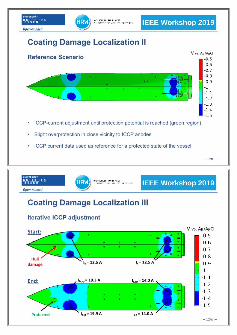
Coating Damage Localization II
Reference ScenarioV vs. Ag/AgCl
• ICCP-current adjustment until protection potential is reached (green region)
• Slight overprotection in close vicinity to ICCP anodes
• ICCP current data used as reference for a protected state of the vessel
– 12/17 –
Coating Damage Localization III
Iterative ICCP adjustment
V vs. Ag/AgCl
Hulldamage Ib = 12.5 A Is = 12.5 A
Ib,sp = 19.3 A Is,sp = 14.0 A
Ib,p = 19.9 A Is,p = 14.0 A
Start:
End:
Protected

– 13/17 –
Coating Damage Localization IV
Setup for Artificial Neural Network (ANN)
• Separation of hull in 12 different sectors (output layer)
• Total number of 2000 simulations for ICCP currents were carried out (input layer)
• Coating damage randomly positioned along hull
• 80% training data, 10% validation data, 10% test data
– 14/17 –
Coating Damage Localization V
Training Results of ANN
Position ofcoating damage
ANNpredicition

– 15/17 –
Conclusion
• Using realistic polarization data, electrochemical behavior can be simulated properly
• Iterative ICCP-current adjustment allows reestablishing of corrosion protective state of coating damage
• Utilizing a sectorized ship model for the ANN results in a correct prediction of the ANN of approximately 90% using only ICCP current information
• ANN could be tested on a simplified physical model and results can be compared to real measurement data
• Ideal case: ANN prediction can be implemented in real ship monitoring systems in the future
– 16/17 –
Thank you for your attention!
Questions?

– 17/17 –
Literature
Wikipedia. “Wikipedia – The Free Encyclopedia.” Antifouling (in french). https://fr.wikipedia.org/wiki/Antifouling (accessed Jun. 4, 2019)
[1]
Wikipedia. “Wikipedia – The Free Encyclopedia.” Cathodic protection (in french). https://fr.wikipedia.org/wiki/Protection_cathodique (accessed Jun. 4, 2019)
[2]
Commericial & Specialised Diving LTD. “Commericial & SpecialisedDiving LTD.” Anode Installation.https://commercialandspecialiseddiving.wordpress.com/2016/01/25/anode-installation/ (accessed Jun. 4, 2019)
[3]
Ship Technology. “Anode Supply.” Anode Supply Images. https://www.ship-technology.com/contractors/corrosion/anode-supply/(accessed Jun. 4, 2019)
[4]