Defect dynamics in active nematics
16
Defect dynamics in active nematics Luca Giomi, 1 Mark J. Bowick, 2 Prashant Mishra, 3 Rastko Sknepnek, 4 and M. Cristina Marchetti 2 1 SISSA, International School for Advanced Studies, Via Bonomea 265, 34136 Trieste, Italy 2 Physics Department and Syracuse Biomaterials Institute, Syracuse University, Syracuse NY 13244, USA 3 Physics Department, Syracuse University, Syracuse NY 13244, USA 4 School of Engineering, Physics, and Mathematics, University of Dundee, Dundee DD1 4HN, UK Topological defects are distinctive signatures of liquid crystals. They profoundly affect the vis- coelastic behavior of the fluid by constraining the orientational structure in a way that inevitably requires global changes not achievable with any set of local deformations. In active nematic liquid crystals topological defects not only dictate the global structure of the director, but also act as local sources of motion, behaving as self-propelled particles. In this article we present a detailed analytical and numerical study of the mechanics of topological defects in active nematic liquid crystals. Keywords: Active liquid crystals, topological defects, self-propelled particles, chaotic dynamics I. INTRODUCTION Active liquid crystals are nonequilibrium fluids com- posed of internally driven elongated units. Examples of active systems that can exhibit liquid crystalline order include mixtures of cytoskeletal filaments and associated motor proteins, bacterial suspensions, the cell cytoskele- ton and even non-living analogues, such as monolayers of vibrated granular rods [1]. The key feature that dis- tinguishes active liquid crystals from their well-studied passive counterparts is that they are maintained out of equilibrium not by an external force applied at the sys- tem’s boundary, such as an imposed shear, but by an energy input on each individual unit. The energy fed into the system at the microscopic scale is then trans- formed into organized motion at the large scale. This type of “reverse energy cascade” is the hallmark of ac- tive systems. In active liquid crystals the large scale self- organized flows resulting from activity further couple to orientational order, yielding a very rich behavior. Novel effects that have been predicted theoretically or observed in simulations and experiments include spontaneous lam- inar flow [2–4], large density fluctuations [5–7], unusual rheological properties [8–10], excitability [11, 12] and low Reynolds number “turbulence” [11–17]. Ordered liquid crystalline phases of active matter can be classified according to their symmetry and to the na- ture of the forces that the active units exert on the en- vironment. Active particles are often elongated objects with a head and a tail, hence intrinsically polar, such as bacteria or birds. Such systems can order in states with ferromagnetic (polar) order, where all units are on aver- age aligned in a fixed direction. In this case the ordered state is also a macroscopically moving state. Polar active particles can also order in states with nematic or apolar order, where the particles are aligned along the same axis, but with random head/tail orientation. In this case the ordered state has apolar or nematic symmetry: if the di- rection of mean order is denoted by a unit vector n then the ordered state is invariant under n →-n and has zero mean velocity. Some active units are intrinsically apolar, such as vibrated rods [7], melanocytes [18] and some fibroblasts [19], and order in states with nematic symmetry. In addition to the distinction based on symmetry of the ordered state, active systems can be further classi- fied by the type of stresses or flows they impose on the surrounding medium. These can be contractile, as in actomyosin networks or in migrating cell layers, or ex- tensile, as in suspensions of microtubule bundles or in most bacteria [1]. In the context of swimming microor- ganisms or artificial swimmers, units that exert exten- sile forces on the surrounding fluid are known as push- ers, while those that exert contractile forces are known as pullers. Most bacteria are pushers, while the alga Chlamydomonas is an example of a puller. The extensile or contractile nature of active stresses affects the stability of ordered states [20]. In this paper we focus on the rich dynamics of active liquid crystals with nematic symmetry. We consider both extensile [21, 22] and contractile [19] systems. Previous work has highlighted the rich dynamics that arises in ac- tive nematics from the interplay of activity, orientational order and flow [2–4, 11, 12, 23]. More recently it was suggested that topological defects play an important role in mediating and driving turbulent-like active flows [14– 17, 21, 24]. Topological defects are inhomogeneous configurations of the order field that provide a distinctive signature of liquid crystalline order and have been extensively studied in passive nematics. For passive nematics, defects may be generated through boundary conditions, externally ap- plied fields, or via sufficiently rapid quenches from the disordered to the ordered state [25–27]. When the con- straints are removed, or the system is given time to equi- librate, the defects ultimately annihilate and the system reaches a homogeneous ordered state that minimizes the free energy. The structure of the topological defects is in- timately related to the broken symmetry of the ordered state and effectively provides a “fingerprint” of such a symmetry. When the ordered state has ferromagnetic (polar) symmetry, the lowest energy defect configurations are the charge +1 vortices and asters (monopoles), while in states with nematic symmetry charge ±1/2 defects, arXiv:1403.5254v2 [cond-mat.soft] 26 Mar 2014
Transcript of Defect dynamics in active nematics

Defect dynamics in active nematics
Luca Giomi,1 Mark J. Bowick,2 Prashant Mishra,3 Rastko Sknepnek,4 and M. Cristina Marchetti2
1SISSA, International School for Advanced Studies, Via Bonomea 265, 34136 Trieste, Italy2Physics Department and Syracuse Biomaterials Institute, Syracuse University, Syracuse NY 13244, USA
3Physics Department, Syracuse University, Syracuse NY 13244, USA4School of Engineering, Physics, and Mathematics, University of Dundee, Dundee DD1 4HN, UK
Topological defects are distinctive signatures of liquid crystals. They profoundly affect the vis-coelastic behavior of the fluid by constraining the orientational structure in a way that inevitablyrequires global changes not achievable with any set of local deformations. In active nematic liquidcrystals topological defects not only dictate the global structure of the director, but also act as localsources of motion, behaving as self-propelled particles. In this article we present a detailed analyticaland numerical study of the mechanics of topological defects in active nematic liquid crystals.
Keywords: Active liquid crystals, topological defects, self-propelled particles, chaotic dynamics
I. INTRODUCTION
Active liquid crystals are nonequilibrium fluids com-posed of internally driven elongated units. Examples ofactive systems that can exhibit liquid crystalline orderinclude mixtures of cytoskeletal filaments and associatedmotor proteins, bacterial suspensions, the cell cytoskele-ton and even non-living analogues, such as monolayersof vibrated granular rods [1]. The key feature that dis-tinguishes active liquid crystals from their well-studiedpassive counterparts is that they are maintained out ofequilibrium not by an external force applied at the sys-tem’s boundary, such as an imposed shear, but by anenergy input on each individual unit. The energy fedinto the system at the microscopic scale is then trans-formed into organized motion at the large scale. Thistype of “reverse energy cascade” is the hallmark of ac-tive systems. In active liquid crystals the large scale self-organized flows resulting from activity further couple toorientational order, yielding a very rich behavior. Noveleffects that have been predicted theoretically or observedin simulations and experiments include spontaneous lam-inar flow [2–4], large density fluctuations [5–7], unusualrheological properties [8–10], excitability [11, 12] and lowReynolds number “turbulence” [11–17].
Ordered liquid crystalline phases of active matter canbe classified according to their symmetry and to the na-ture of the forces that the active units exert on the en-vironment. Active particles are often elongated objectswith a head and a tail, hence intrinsically polar, such asbacteria or birds. Such systems can order in states withferromagnetic (polar) order, where all units are on aver-age aligned in a fixed direction. In this case the orderedstate is also a macroscopically moving state. Polar activeparticles can also order in states with nematic or apolarorder, where the particles are aligned along the same axis,but with random head/tail orientation. In this case theordered state has apolar or nematic symmetry: if the di-rection of mean order is denoted by a unit vector n thenthe ordered state is invariant under n → −n and haszero mean velocity. Some active units are intrinsicallyapolar, such as vibrated rods [7], melanocytes [18] and
some fibroblasts [19], and order in states with nematicsymmetry.
In addition to the distinction based on symmetry ofthe ordered state, active systems can be further classi-fied by the type of stresses or flows they impose on thesurrounding medium. These can be contractile, as inactomyosin networks or in migrating cell layers, or ex-tensile, as in suspensions of microtubule bundles or inmost bacteria [1]. In the context of swimming microor-ganisms or artificial swimmers, units that exert exten-sile forces on the surrounding fluid are known as push-ers, while those that exert contractile forces are knownas pullers. Most bacteria are pushers, while the algaChlamydomonas is an example of a puller. The extensileor contractile nature of active stresses affects the stabilityof ordered states [20].
In this paper we focus on the rich dynamics of activeliquid crystals with nematic symmetry. We consider bothextensile [21, 22] and contractile [19] systems. Previouswork has highlighted the rich dynamics that arises in ac-tive nematics from the interplay of activity, orientationalorder and flow [2–4, 11, 12, 23]. More recently it wassuggested that topological defects play an important rolein mediating and driving turbulent-like active flows [14–17, 21, 24].
Topological defects are inhomogeneous configurationsof the order field that provide a distinctive signature ofliquid crystalline order and have been extensively studiedin passive nematics. For passive nematics, defects may begenerated through boundary conditions, externally ap-plied fields, or via sufficiently rapid quenches from thedisordered to the ordered state [25–27]. When the con-straints are removed, or the system is given time to equi-librate, the defects ultimately annihilate and the systemreaches a homogeneous ordered state that minimizes thefree energy. The structure of the topological defects is in-timately related to the broken symmetry of the orderedstate and effectively provides a “fingerprint” of such asymmetry. When the ordered state has ferromagnetic(polar) symmetry, the lowest energy defect configurationsare the charge +1 vortices and asters (monopoles), whilein states with nematic symmetry charge ±1/2 defects,
arX
iv:1
403.
5254
v2 [
cond
-mat
.sof
t] 2
6 M
ar 2
014

2
known as disclinations, are possible [28] and have thelowest energy. The structure of the topological defectstherefore provides an important tool for classifying thebroken symmetry of liquid crystalline states.
In active liquid crystals, in contrast to passive ones, de-fect configurations can occur spontaneously in the bulkand be continuously regenerated by the local energy in-put, as demonstrated in experiments [18, 19, 21, 22].While the aster and vortex defects that occur in polaractive systems [29, 30] have been studied for some time[23, 31–33], the properties of defects in active nemat-ics have only recently become the focus of experimentaland theoretical attention. Disclinations have been iden-tified in monolayers of vibrated granular rods [7], in ac-tive nematic gels assembled in vitro from microtubulesand kinesins [21], in dense cell monolayers [18, 19], andin living liquid crystals obtained by injecting bacteriain chromonic liquid crystals [22]. In bulk suspensionsof microtubule bundles the defects drive spontaneousflows [21]. When confined at an oil/water interface, fur-thermore, the same suspensions form a two-dimensionalactive nematic film, with self-sustained flows resemblingcytoplasmic streaming and the continuous creation andannihilation of defect pairs [21].
Recent work by us [24] and others [14–17, 34] has be-gun to systematically examine the effect of activity onthe dynamics of disclinations in a nematic liquid crys-talline film. We demonstrated that +1/2 disclinations inactive liquid crystals behave like self-propelled particleswith an active speed proportional to activity. The di-rection of active motion is controlled by the extensile orcontractile nature of the active stresses. For certain rel-ative orientations of pairs of defects of opposite strengththis self propulsion can overcome the equilibrium repul-sive interaction among pairs of opposite-sign defects, al-lowing for dynamical states with an average sustainedconcentration of defect-antidefect pairs. In related work,Thampi et al. [14] suggested that the mean distance be-tween defects in these turbulent states may be stronglycorrelated with the correlation length of fluctuations inthe flow velocity, and only weakly dependent on activity.In the rest of this paper we first review the hydrodynamicdescription of active nematics and the instabilities of thehomogeneous ordered state. In Section V we present theresults of a systematic numerical study of the various flowregimes induced by activity. Each regime is characterizedin terms of flow patterns and defect proliferation. Thechaotic regime exhibits a steady number of defects thatpersist in time. This is made possible by active flowsthat drive directed motion of the comet-like +1/2 de-fects, generating, for certain relative orientations of twoopposite sign defects, an effective repulsive interactionbetween the pair. The mechanisms for this active defectdynamics are analyzed in Sections III and IV, where wediscuss individual defect dynamics and pair annihilationin active nematics, respectively. We conclude with a briefdiscussion highlighting open questions.
II. ACTIVE NEMATODYNAMICS
A. Governing Equations
We consider a uniaxial active nematic liquid crystalin two dimensions. The two-dimensional limit is appro-priate to describe the experiments by Sanchez et al. [21],where the microtubule bundles confined to a water-oil in-terface form an effectively two-dimensional dense nematicsuspension, but also of considerable interest in its ownright. The hydrodynamic equations of active nematic liq-uid crystals have been derived by coarse-graining a semi-microscopic model of cytoskeletal filaments crosslinkedby clusters of motor proteins [35]. They can also simplybe obtained from the hydrodynamic equations of pas-sive systems by the addition of nonequilibrium stressesand currents due to activity [1, 3, 11, 12, 32, 36, 37].We consider here an incompressible suspension wherethe total density ρ of active bundles and solvent is con-stant. The equations are formulated in terms of theconcentration c of active units, the flow velocity v ofthe suspension and the nematic tensor order parameterQij = S (ninj − δij/2), with n the director field. Thealignment tensor Qij is traceless and symmetric, andhence has only two independent components in two di-mensions. The constraint of constant density ρ requires∇·v = 0. The hydrodynamic equations are given by [11]
Dc
Dt= ∂i
[Dij∂jc+ α1c
2∂jQij], (1a)
ρDviDt
= η∇2vi − ∂ip+ ∂jσij , (1b)
DQijDt
= λSuij +Qikωkj − ωikQkj +1
γHij , (1c)
where D/Dt = ∂t + v · ∇ indicates the material deriva-tive, Dij = D0δij + D1Qij is the anisotropic diffusiontensor, η the viscosity, p the pressure, λ the nematicalignment parameter, and γ the rotational viscosity. Hereuij = (∂ivj + ∂jvi)/2 and ωij = (∂ivj − ∂jvi)/2 are thestrain rate and vorticity tensor, respectively, represent-ing the symmetric and antisymmetric parts of the veloc-ity gradient. The molecular field Hij = −δFLdG/δQijembodies the relaxational dynamics of the nematic ob-tained from the variation of the two-dimensional Landau-de Gennes free energy FLdG =
∫dAfLdG [28], with
fLdG = 12A tr(Q)2 + 1
4C(trQ2)2 + 12K|∇Q|
2 , (2)
where K is an elastic constant with dimensions of en-ergy. For simplicity we restrict ourselves here to the one-elastic constant approximation to the Frank free energy:i.e. equal bend and splay moduli. The coefficients Aand C determine the location of the continuous transi-tion from a homogeneous isotropic state with S = 0 to ahomogeneous nematic state with a finite value of S givenby S =
√−2A/C (where we have used trQ2 = S2/2).

3
We are interested here in a system where the transitionis driven by the concentration of nematogens, as is thecase for a fluid of hard rods of length ` which exhibitsan isotropic-nematic (IN) transition at a concentrationc? = 3π/2`2 in two dimensions. Noting that A and Chave dimensions of energy density (in two dimensions),we choose A = K (c? − c) /2 and C = Kc [12]. This
gives S = S0 =√
1− c?/c0 in a homogeneous state ofdensity c0, so that S0 = 0 for c0 < c? and S0 ≈ 1 forc0 � c?. The ratio
√K/|A| defines a length scale that
corresponds to the equilibrium correlation length of orderparameter fluctuations and diverges at the continuous INtransition [26]. Here we restrict ourselves to mean valuesof concentration well above c?, where this equilibriumcorrelation length is microscopic and is of the order ofthe size ` of the nematogens, which will be used as ourunit of length in the numerical simulation. Finally, thestress tensor σij = σr
ij+σaij is the sum of the elastic stress
due to nematic elasticity,
σrij = −λSHij +QikHkj −HikQkj , (3)
where for simplicity we have neglected the Eriksen stress,and an active contribution, given by [1]
σaij = α2c
2Qij , (4)
which describes stresses exerted by the active particles.The sign of α2 depends on whether the active particlesgenerate contractile or extensile stresses, with α2 > 0for the contractile case and α2 < 0 for extensile sys-tems. Activity yields also a curvature-induced currentgiven by the last term on the right hand side of Eq. (1a),ja = −α1c
2∇ · Q, that drives active units from re-gions populated by fast moving particles to regions ofslow moving particles. The c2 dependence of the activestress and current is appropriate for systems where activ-ity arises from pair interactions among the filaments viacrosslinking motor proteins. The active parameters α1
and α2 will be treated here as purely phenomenological.In microscopic models they are found to depend on theconcentration of active crosslinkers and on the consump-tion rate of adenosine triphosphate (ATP) [38, 39].
B. Linear Stability
The hydrodynamic equations of an active nematic havetwo homogeneous stationary solutions, with c = c0 andv = 0. For c0 < c? the homogeneous state is disorderedwith S0 = 0. For c0 > c? the homogeneous solution isan ordered nematic state with S0 =
√1− c?/c0. The
linear stability of the ordered state has been studied indetail for the case of a L × L periodic domain [11, 12].It is found that above a critical activity the homogenousstate is unstable to a laminar flowing state. This in-stability corresponds to the spontaneous flow instabilitywell-studied in a channel geometry [2, 4, 40]. The crit-ical activity value associated with the instability of the
FIG. 1: Schematic representation of the region where an ac-tive nematic is linearly unstable to splay (green) and to bend(gray) fluctuations in the plane of the alignment parameter λand the activity α = c20α2. The unstable regions are boundedby the critical activity given in Eq. (5). Flow tumbling ex-tensile nematic with |λ| < 1 are unstable to bend when ac-tive stresses are extensile (α < 0) and to splay when activestresses are contractile (α > 0). Conversely, strongly flowaligning (|λ| � 1) are unstable to splay when active stressesare extensile (α < 0) and to bend when active stresses arecontractile (α > 0).
homogeneous state is given by [12]
α±2 = ±4π2K[2η + γS20 (1∓ λ)
2]
γc20L2S0 (1∓ λ)
. (5)
For |α2| > |α+2 | the system is subject to spontaneous
splay deformations characterized by the instability of thefirst transverse mode. For |α2| > |α−2 |, on the other hand,the instability is determined by the first longitudinalmode corresponding to bending deformations. Note thatthe sign of α±2 depends both on the sign of the fractionand the sign of the term 1∓λ in the denominator. Thusflow-aligning nematics (|λ| > 1) are unstable to splay un-der the effect of an extensile active stress (α2 < α+
2 < 0)and to bending under the effect of a contractile activestress (α2 > α−2 > 0). Vice versa, flow-tumbling ne-matics (−1 < λ < 1) are unstable to bending under theeffect of an extensile active stress (α2 < α−2 < 0) andto splay under the effect of a contractile active stress(α2 > α+
2 > 0) (see Fig.1). In this paper we focus ex-clusively on flow-tumbling systems and discuss both thecases of extensile and contractile stresses.
C. Dimensionless Units and Numerical Methods
To render Eqs. (1) dimensionless, we scale distances bythe length of the active nematogens `, set by the criti-cal concentration c?, stresses by the elastic stress of the
4
nematic phase σ = K/`2 and time by τp = η`2/K rep-resenting the ratio between viscous and elastic stress. Inthese dimensionless units we take α1 = |α2|/2 and weintroduce
α = α2c20 , (6)
as the fundamental measure of active stress. This willserve as the control parameter throughout this work.
The numerical calculations presented in Sec. IV andV are performed via finite differences on a square grid of2562 points. The time integration was performed via afourth order Runge-Kutta method with time step ∆t =10−3. Except where mentioned otherwise, the numericalcalculations described in this section use the parametervalues D0 = D1 = 1, λ = 0.1, c0 = 2c? (corresponding toS0 = 0.707) and L = 20.
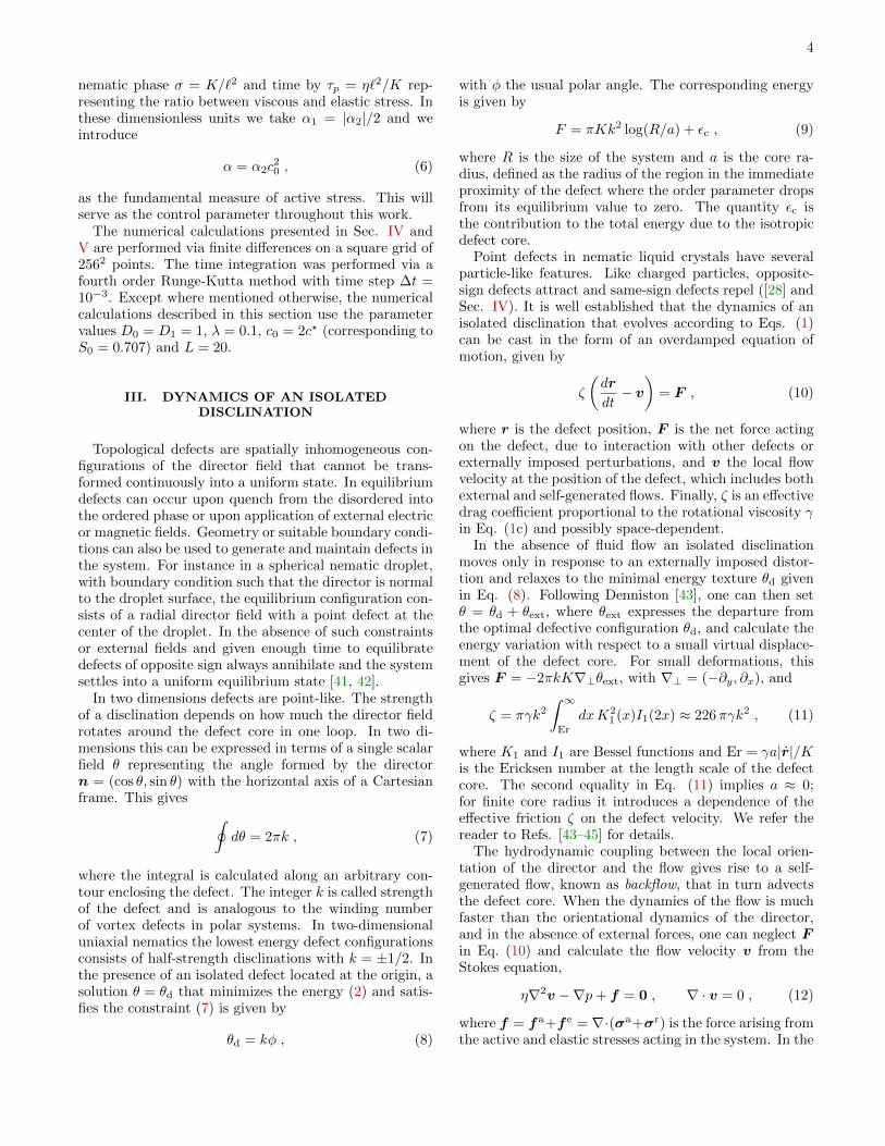
III. DYNAMICS OF AN ISOLATEDDISCLINATION
Topological defects are spatially inhomogeneous con-figurations of the director field that cannot be trans-formed continuously into a uniform state. In equilibriumdefects can occur upon quench from the disordered intothe ordered phase or upon application of external electricor magnetic fields. Geometry or suitable boundary condi-tions can also be used to generate and maintain defects inthe system. For instance in a spherical nematic droplet,with boundary condition such that the director is normalto the droplet surface, the equilibrium configuration con-sists of a radial director field with a point defect at thecenter of the droplet. In the absence of such constraintsor external fields and given enough time to equilibratedefects of opposite sign always annihilate and the systemsettles into a uniform equilibrium state [41, 42].
In two dimensions defects are point-like. The strengthof a disclination depends on how much the director fieldrotates around the defect core in one loop. In two di-mensions this can be expressed in terms of a single scalarfield θ representing the angle formed by the directorn = (cos θ, sin θ) with the horizontal axis of a Cartesianframe. This gives ∮
dθ = 2πk , (7)
where the integral is calculated along an arbitrary con-tour enclosing the defect. The integer k is called strengthof the defect and is analogous to the winding numberof vortex defects in polar systems. In two-dimensionaluniaxial nematics the lowest energy defect configurationsconsists of half-strength disclinations with k = ±1/2. Inthe presence of an isolated defect located at the origin, asolution θ = θd that minimizes the energy (2) and satis-fies the constraint (7) is given by
θd = kφ , (8)
with φ the usual polar angle. The corresponding energyis given by
F = πKk2 log(R/a) + εc , (9)
where R is the size of the system and a is the core ra-dius, defined as the radius of the region in the immediateproximity of the defect where the order parameter dropsfrom its equilibrium value to zero. The quantity εc isthe contribution to the total energy due to the isotropicdefect core.
Point defects in nematic liquid crystals have severalparticle-like features. Like charged particles, opposite-sign defects attract and same-sign defects repel ([28] andSec. IV). It is well established that the dynamics of anisolated disclination that evolves according to Eqs. (1)can be cast in the form of an overdamped equation ofmotion, given by
ζ
(dr
dt− v
)= F , (10)
where r is the defect position, F is the net force actingon the defect, due to interaction with other defects orexternally imposed perturbations, and v the local flowvelocity at the position of the defect, which includes bothexternal and self-generated flows. Finally, ζ is an effectivedrag coefficient proportional to the rotational viscosity γin Eq. (1c) and possibly space-dependent.
In the absence of fluid flow an isolated disclinationmoves only in response to an externally imposed distor-tion and relaxes to the minimal energy texture θd givenin Eq. (8). Following Denniston [43], one can then setθ = θd + θext, where θext expresses the departure fromthe optimal defective configuration θd, and calculate theenergy variation with respect to a small virtual displace-ment of the defect core. For small deformations, thisgives F = −2πkK∇⊥θext, with ∇⊥ = (−∂y, ∂x), and
ζ = πγk2∫ ∞Er
dxK21 (x)I1(2x) ≈ 226πγk2 , (11)
where K1 and I1 are Bessel functions and Er = γa|r|/Kis the Ericksen number at the length scale of the defectcore. The second equality in Eq. (11) implies a ≈ 0;for finite core radius it introduces a dependence of theeffective friction ζ on the defect velocity. We refer thereader to Refs. [43–45] for details.
The hydrodynamic coupling between the local orien-tation of the director and the flow gives rise to a self-generated flow, known as backflow, that in turn advectsthe defect core. When the dynamics of the flow is muchfaster than the orientational dynamics of the director,and in the absence of external forces, one can neglect Fin Eq. (10) and calculate the flow velocity v from theStokes equation,
η∇2v −∇p+ f = 0 , ∇ · v = 0 , (12)
where f = fa+f e = ∇·(σa+σr) is the force arising fromthe active and elastic stresses acting in the system. In the

5
case of isolated defects this scenario is generally realisticfor η/γ � 1 and even in a system containing multipledefects this purely advective dynamics continues to holdas long as the defects are sufficiently far apart (see Sec.IV). The general case in which both v and F are non-zerowas discussed by Kats et al. [46].
In the remainder of this section we consider the regimein which η/γ � 1 and calculate the backflow due tothe stresses arising in the presence of isolated k = ±1/2disclinations. Let us then consider a ±1/2 disclinationlocated at the origin of a circular domain of size R. Thedomain might represent either the entire system or, morerealistically, the defect-free portion of the system sur-rounding a given central defect. We will refer to this asthe range of a defect. Because of the linearity of theStokes equation, the solution of Eq. (12) can be writ-ten as v = v0 + va + ve, where v0 is the solution of thehomogeneous Stokes equation, while va and ve are theflows produced by the active and elastic force, respec-tively. The solution can be expressed as the convolutionof the two-dimensional Oseen tensor with the force perunit area,
vi(r) =
∫dA′Gij(r − r′)fj(r′) , (13)
where Gij is the two-dimensional Oseen tensor [47], givenby
Gij(r) =1
4πη
[(logLr− 1
)δij +
rirjr2
], (14)
with L a length scale adjusted to obtain the desired be-havior at the boundary. Taking n = (cos kφ, sin kφ), withk = ±1/2, and assuming uniform concentration and ne-matic order parameter outside the defect core, the bodyforce due to activity can be calculated straightforwardlyas
fa = ∇ · σa =α
2r
{x k = +1/2 ,
− cos 2φ x+ sin 2φ y k = −1/2 ,
where, for simplicity, we have assumed S0 = 1 outsidethe core. Using this in Eq. (13), and using (14), yields,after some algebraic manipulation,
va+(r, φ) =α
12η{[3(R− r) + r cos 2φ] x+ r sin 2φ y} , (15a)
va−(r, φ) =αr
12ηR
{[(3
4r −R
)cos 2φ− R
5cos 4φ
]x+
[(3
4r −R
)sin 2φ+
R
5sin 4φ
]y
}. (15b)
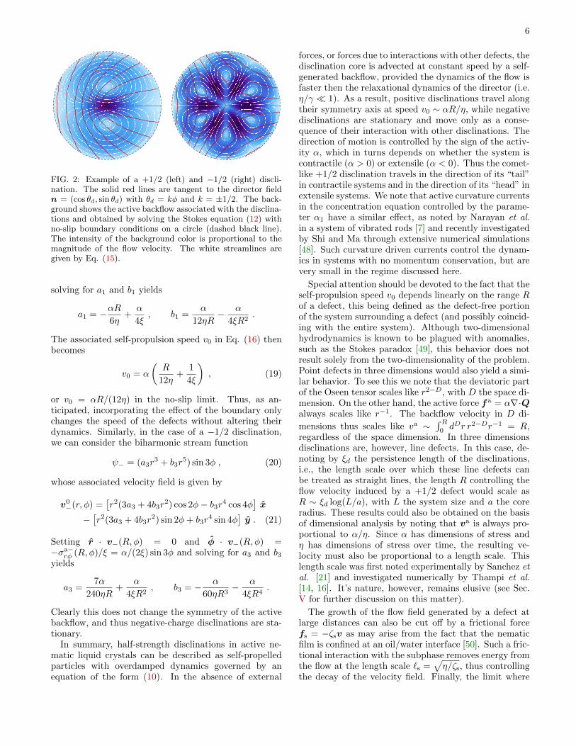
A plot of these flow fields is shown in Fig. 2. Settingv = va+(0, φ) in Eq. (10) we find that active +1/2 discli-nations self-propel at constant speed along their symme-try axis (x in this setting), and their equation of motioncan be written as
ζdr+dt
= v0x , (16)
where v0 = αR/(4η). On the other hand, va−(0, φ) = 0,and so −1/2 disclinations are not propelled by the activebackflow, but rather move solely under the effect of theelastic force produced by other defects. It is crucial tonotice that the self-propulsion speed v0 scales linearlywith the active stress α and so disclinations in contractile(α > 0) and extensile (α < 0) active nematic suspensionsself-propel in opposite directions.
Equations (15) can be complemented with variouskinds of boundary conditions, which, however, have no ef-fect on the qualitative features of the solution and, moreimportantly, on the dynamics of the defects. To illus-trate this point we consider a slippery interface, suchthat vr(R,φ) = 0 and σa
rφ = −ξvφ(R,φ), where ξ is the
coefficient associated with the frictional force exerted bythe interface on the fluid. If the domain of Eq. (12) isinterpreted as a container, then ξ is the actual frictionalcoefficient of the container wall. On the other hand, ifthe domain is interpreted as the range of a defect, thenξ ∼ ηh, where h is the thickness of the boundary layer be-tween the ranges of neighboring defects. No-slip bound-ary conditions can be recovered in the limit ξ →∞.
A solution v0 of the homogeneous Stokes equation en-forcing the boundary conditions for the active backflowinduced by the +1/2 disclination can be found from thefollowing biharmonic stream function
ψ+ = (a1r + b1r3) sinφ , (17)
with a1 and b1 constants. The corresponding velocityfield v0+ = (∂yψ,−∂xψ) is given by
v0+(r, φ) = [a1 + b1r2(2− cos 2φ)] x− b1r2 sin 2φ y . (18)
Then, setting r · v+(R,φ) = 0 and φ · v+(R,φ) =−σa+
rφ (R,φ)/ξ = α/(2ξ) sinφ, with v+ = v0+ + va+, and
6
FIG. 2: Example of a +1/2 (left) and −1/2 (right) discli-nation. The solid red lines are tangent to the director fieldn = (cos θd, sin θd) with θd = kφ and k = ±1/2. The back-ground shows the active backflow associated with the disclina-tions and obtained by solving the Stokes equation (12) withno-slip boundary conditions on a circle (dashed black line).The intensity of the background color is proportional to themagnitude of the flow velocity. The white streamlines aregiven by Eq. (15).
solving for a1 and b1 yields
a1 = −αR6η
+α
4ξ, b1 =
α
12ηR− α
4ξR2.
The associated self-propulsion speed v0 in Eq. (16) thenbecomes
v0 = α
(R
12η+
1
4ξ
), (19)
or v0 = αR/(12η) in the no-slip limit. Thus, as an-ticipated, incorporating the effect of the boundary onlychanges the speed of the defects without altering theirdynamics. Similarly, in the case of a −1/2 disclination,we can consider the biharmonic stream function
ψ− = (a3r3 + b3r
5) sin 3φ , (20)
whose associated velocity field is given by
v0−(r, φ) =[r2(3a3 + 4b3r
2) cos 2φ− b3r4 cos 4φ]x
−[r2(3a3 + 4b3r
2) sin 2φ+ b3r4 sin 4φ
]y . (21)
Setting r · v−(R,φ) = 0 and φ · v−(R,φ) =−σa−
rφ (R,φ)/ξ = α/(2ξ) sin 3φ and solving for a3 and b3yields
a3 =7α
240ηR+
α
4ξR2, b3 = − α
60ηR3− α
4ξR4.
Clearly this does not change the symmetry of the activebackflow, and thus negative-charge disclinations are sta-tionary.
In summary, half-strength disclinations in active ne-matic liquid crystals can be described as self-propelledparticles with overdamped dynamics governed by anequation of the form (10). In the absence of external
forces, or forces due to interactions with other defects, thedisclination core is advected at constant speed by a self-generated backflow, provided the dynamics of the flow isfaster then the relaxational dynamics of the director (i.e.η/γ � 1). As a result, positive disclinations travel alongtheir symmetry axis at speed v0 ∼ αR/η, while negativedisclinations are stationary and move only as a conse-quence of their interaction with other disclinations. Thedirection of motion is controlled by the sign of the activ-ity α, which in turns depends on whether the system iscontractile (α > 0) or extensile (α < 0). Thus the comet-like +1/2 disclination travels in the direction of its “tail”in contractile systems and in the direction of its “head” inextensile systems. We note that active curvature currentsin the concentration equation controlled by the parame-ter α1 have a similar effect, as noted by Narayan et al.in a system of vibrated rods [7] and recently investigatedby Shi and Ma through extensive numerical simulations[48]. Such curvature driven currents control the dynam-ics in systems with no momentum conservation, but arevery small in the regime discussed here.
Special attention should be devoted to the fact that theself-propulsion speed v0 depends linearly on the range Rof a defect, this being defined as the defect-free portionof the system surrounding a defect (and possibly coincid-ing with the entire system). Although two-dimensionalhydrodynamics is known to be plagued with anomalies,such as the Stokes paradox [49], this behavior does notresult solely from the two-dimensionality of the problem.Point defects in three dimensions would also yield a simi-lar behavior. To see this we note that the deviatoric partof the Oseen tensor scales like r2−D, with D the space di-mension. On the other hand, the active force fa = α∇·Qalways scales like r−1. The backflow velocity in D di-
mensions thus scales like va ∼∫ R0dDr r2−Dr−1 = R,
regardless of the space dimension. In three dimensionsdisclinations are, however, line defects. In this case, de-noting by ξd the persistence length of the disclinations,i.e., the length scale over which these line defects canbe treated as straight lines, the length R controlling theflow velocity induced by a +1/2 defect would scale asR ∼ ξd log(L/a), with L the system size and a the coreradius. These results could also be obtained on the basisof dimensional analysis by noting that va is always pro-portional to α/η. Since α has dimensions of stress andη has dimensions of stress over time, the resulting ve-locity must also be proportional to a length scale. Thislength scale was first noted experimentally by Sanchez etal. [21] and investigated numerically by Thampi et al.[14, 16]. It’s nature, however, remains elusive (see Sec.V for further discussion on this matter).
The growth of the flow field generated by a defect atlarge distances can also be cut off by a frictional forcefs = −ζsv as may arise from the fact that the nematicfilm is confined at an oil/water interface [50]. Such a fric-tional interaction with the subphase removes energy fromthe flow at the length scale `s =
√η/ζs, thus controlling
the decay of the velocity field. Finally, the limit where

7
FIG. 3: Snapshots of a disclination pair shortly after the be-ginning of relaxation. (Top) Director field (black lines) su-perimposed on a heat map of the nematic order parameterand (bottom) flow field (arrows) superimposed on a heat mapof the concentration for an extensile system with α = −0.8(a),(c) and a contractile system with α = 0.8 (b),(d). Inthe top images the color denotes the magnitude of the ne-matic order parameter S relative to its equilibrium valueS0 =
√1− c?/c0 = 1/
√2. In the bottom images the color
denotes the magnitude of the concentration c relative to theaverage value c0 = 2c?. Depending on the sign of α, thebackflow tends to speed up (α > 0) or slow down (α < 0) theannihilation process by increasing or decreasing the velocityof the +1/2 disclination. For α negative and sufficiently largein magnitude, the +1/2 defect reverses its direction of motion(c) and escapes annihilation.
the friction dominates viscous forces corresponding to ano-slip Hele-Shaw geometry has been discussed in detailby Pismen [34]. In this case the flow generated by a singledisclination is found to decay as ∼ r−3 at large distancesfrom the defect.
IV. ANNIHILATION DYNAMICS OF DEFECTPAIRS
In this section we discuss the annihilation of a pair ofoppositely charged disclinations. The study of the anni-hilation dynamics of defect-antidefect pairs is a maturetopic in the liquid crystals field and has been subject tonumerous investigations [43, 44, 51–55]. In the simplestsetting [28], one considers a pair of k = ±1/2 disclina-tions located at r± = (x±, 0) and separated by a distance
∆ = x+ − x− (Fig. 3). The energy of the pair is givenby
Epair = 2πk2K log(∆/a) + 2εc . (22)
Each defect experiences an elastic force of the form F± =−(∂Epair/∂x±) x and thus, in the absence of backflow,Eq. (10) can be cast in the form
dx±dt
= ∓ κ
x+ − x−, (23)
where κ = 2πk2K/ζ. This yields
d∆
dt= −2κ
∆, (24)
so that the distance between annihilating defects de-creases as a square-root, ∆(t) ∝
√ta − t, with ta the
annihilation time. More precise calculations have shownthat the effective friction is itself a function of the de-fect separation [44, 45], ζ = ζ0 log(∆/a), although thisdoes not imply substantial changes in the overall pic-ture. This simple model predicts that the defect andantidefect approach each other along symmetric trajec-tories and annihilate at ∆(0)/2 in a time ta = ∆2(0)/4κ.The backflow produced by the balance of elastic and vis-cous stresses [51, 55], as well as the anchoring conditionsat the boundary [52], can produce an asymmetry in thetrajectories of the annihilating defects or even suppressannihilation when the defects are initially far from eachother or the anchoring is sufficiently strong.
To understand how activity changes the simple annihi-lation dynamics described so far, we have integrated nu-merically Eqs. (1) for an initial configuration of uniformconcentration and zero flow velocity, with two disclina-tions of charge ±1/2 symmetrically located with respectto the center of the box along the x−axis. Fig. 3 shows asnapshot of the order parameter and flow field shortly af-ter the beginning of the relaxation for both a contractileand extensile system, with α = ±0.8 in the units definedin Sec. II C.
In contractile systems active backflow yields a netspeed-up of the +1/2 defect towards its antidefect forthe annihilation geometry shown in Fig. 3b. In extensilesystems, with α < 0, backflow drives the +1/2 defect tomove towards its head, away from its −1/2 partner inthe configuration of Fig. 3b, acting like an effectively re-pulsive interaction. If the initial positions of the defectsare exchanged, the behavior is reversed. The effective at-traction or repulsion between oppositively charged activedefects is thus dictated by both the contractile or exten-sile nature of the active stresses, which determines thedirection of the backflow, and the relative orientation ofthe defects, as summarized in Fig. 4. This effect has beenobserved in experiments with extensile microtubules andkinesin assemblies [21] and can be understood on the ba-sis of the hydrodynamic approach embodied in Eqs. (1).In Fig. 5 we have reproduced from Ref. [21] a sequenceof snapshots showing a pair of ±1/2 disclinations moving

8
FIG. 4: Schematic representation of the effective attrac-tive/repulsive interaction promoted by the active backflow.Depending on the sign of the active stress α, +1/2 disclina-tions self-propel in the direction of their “tail” (contractile)or “head” (extensile). Based on the mutual orientation of thedefects, this can lead to an attractive or repulsive interaction.
FIG. 5: Defect pair production in an active suspension ofmicrotubules and kinesin (top) and the same phenomenonobserved in our numerical simulation of an extensile nematicfluid with γ = 100 and α = −2. The experimental picturesare reprinted with permission from T. Sanchez et al., Nature(London) 491, 431 (2012). Copyright 2012, Macmillan.
apart from each other together with the same behaviorobserved in our simulations.
Figs. 6a and 6b show the trajectories of the active de-fects, with the red and blue line representing the +1/2and −1/2 disclination respectively. The tracks end whenthe cores of the two defects merge. For small activity andsmall values of the rotational viscosity γ, the trajectoriesresemble those obtained for passive systems [51, 55]. Atlarge values of activity, however, the asymmetry in defectdynamics becomes more pronounced, and when the ac-tivity dominates over orientational relaxation, the +1/2disclination moves independently along its symmetry axiswith a speed v0 ∼ αR/η (see Sec. III) whose direction isdictated by the sign of α. This behavior is clearly visiblein Fig. 6c, showing the defect separation ∆(t) as a func-tion of time. For γ sufficiently large, the trajectories arecharacterized by two regimes. For large separation thedynamics is dominated by the active backflow, and thus∆(t) ∝ −α and ∆(t) ∝ −αt. Once the defects are aboutto annihilate, the attractive force takes over, and the de-fects behave as in the passive case with ∆(t) ∝
√ta − t.
This behavior can be understood straightforwardly
FIG. 6: Defect trajectories and annihilation times obtainedfrom a numerical integration of Eqs. (1) for various γ andα values. (a) Defect trajectories for γ = 5 and various αvalues (indicated in the plot). The upper (red) and lower(blue) curves correspond to the positive and negative discli-nation, respectively. The defects annihilate where the twocurves merge. (b) The same plot for γ = 10. Slowing downthe relaxational dynamics of the nematic phase increases theannihilation time and for α = −0.8 reverses the direction ofmotion of the +1/2 disclination. (c) Defect separation as afunction of time for α = 0.8 and various γ values. (d) An-nihilation time normalized by the corresponding annihilationtime obtained at α = 0 (i.e., t0a). The line is a fit to the modeldescribed in the text.
from the basic concepts of active defect dynamics dis-cussed in Sec. III. Each defect in the pair travels inspace according to Eq. (10), with v given by v(x) =va+(x−x+) +va−(x−x−) and v± given in Eqs. (15) plusa suitable homogeneous solution of the Stokes equationthat enforces the periodic boundary conditions. Next,we retain only the active contribution to the backflowand replace the flow profiles by their constant values atthe core of the defect, with v+(x+) = v0x ∝ −α andv−(x−) = 0. This yields the following simple equationfor the pair separation
d∆
dt= v0 −
2κ
∆. (25)
This equation explicitly captures the two regimes shownin Fig. 6(c) and described earlier. The solution takes theform
∆(t) = ∆(0) + v0t−2κ
v0log
[∆(t)− 2κ
v0
∆(0)− 2κv0
]. (26)
The pair annihilation time ta is determined by ∆(ta) = 0and is given by
ta = −∆(0)
v0− 2κ
v20log[1− v0
2κ∆(0)
]. (27)
9
For passive systems (α = 0) this reduces to t0a =∆2(0)/4κ. This predicts that the annihilation time, nor-malized to its value in passive systems, ta/t
0a, depends
only on ∆(0) v0/2κ ∼ αγ. Figure 6d shows a fit of theannihilation times extracted from the numerics to thissimple formula. The model qualitatively captures the nu-merical behavior. Note also that defects created a finitedistance ∆(0) apart will always separate provided theactivity and hence the magnitude of the self-propulsionvelocity exceeds a critical value vc0 = 2κ/∆(0).
V. DEFECT PROLIFERATION
Pair annihilation is the fundamental mechanism be-hind defect coarsening in nematic liquid crystals [41].Once this mechanism is suppressed by activity, as de-scribed in Sec. IV, the coarsening dynamics is replacedby a new steady state in which pairs of ±1/2 disclinationsare continuously produced and annihilated at constantrate. The chaotic dynamics following from continuousdefect proliferation and annihilation results in turbulentflow [14–17, 24]. In this section we describe the onset ofchaos and the proliferation of defects that are observedfrom numerical solutions of Eqs. (1) upon varying theactivity parameter α and the rotational viscosity γ. Asinitial configurations we take a homogeneous state withthe director field aligned along the x−axis and subjectto a small random perturbation in density and orienta-tion. The equations were then integrated from t = 0 tot = 2× 10³τ (see Sec. II C for a description of units).
Fig. 8 summarizes the various regimes obtained by ex-ploring the (α, γ)−plane: 1 ) a homogeneous, quiescentordered state (H); 2) a periodic flow marked by the emer-gence of relaxation oscillations (O); 3) a non-periodic os-cillatory flow characterized by the formation of “walls”in the nematic phase and the unzipping of these wallsthrough the unbinding of defect pairs (W); 4) a chaoticor “turbulent” state associated with a constant defectdensity (T). The latter three regimes are described inmore detail in the following.
A. Relaxation Oscillations
As described in Refs. [11, 12], relaxation oscillationsoccur in active nematics when |α| exceeds α±2 as the re-sult of the competition of two time scales: the relaxationτp = γ`2/K of the nematic structure and the time scaleτa = η/|α| that controls the rate at which active stressesare injected in the system. When τp < τa, the microstruc-ture can relax to accommodate the active forcing and theordered state is stable. This is a quiescent state, withuniform order parameter. Conversely, when τp > τa, therelaxation of the nematic structure lags behind the injec-tion of active stresses, yielding various dynamical stateswith spatially and temporally inhomogeneous order pa-rameter.
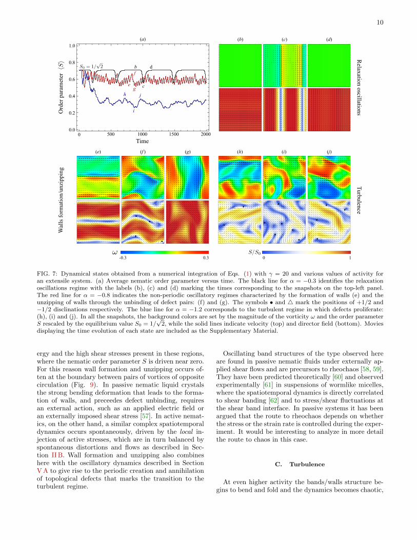
In this regime the dynamics consists of a sequenceof almost stationary passive periods separated by active“bursts” in which the director switches abruptly betweentwo orthogonal orientations (Fig. 7b-d). During passiveperiods, the particle concentration and the nematic orderparameter are nearly uniform across the system, there isno appreciable flow, and the director field is either paral-lel or perpendicular to the x direction (due to the initialconditions). Eventually this configuration breaks downand the director field rotates by 90◦. The rotation ofthe director field is initially localized along narrow ex-tended regions, generating flowing bands similar to thoseobtained in active nematic films [2] (Fig. 7c). The tem-porary distortion of the director field as well as the for-mation of the bands is accompanied by the onset of flowalong the longitudinal direction of the bands, with neigh-boring bands flowing in opposite directions. The flowterminates after the director field rotates and a uniformorientation is restored. The process then repeats.
Depending on whether the active stress fueling the os-cillatory dynamics is contractile or extensile, the rota-tion of the director occurs through an intermediate splayor bending deformation. During bursts, the nematic or-der parameter, otherwise equal to its equilibrium value,drops significantly (Fig. 7a, black line). Without thistransient melting the distortions of the director field re-quired for a burst are unfavorable for any level of activity.
The frequency of the oscillation is proportional to k2α,where k = 2π/L is the wave number of the longest-wavelength mode to go unstable [11, 12]. In spite of thestrong elastic deformation and the dramatic drop in theorder parameter, this regime contains no unbound de-fects.
B. Wall formation and unzipping
For larger values of activity the bend and splay defor-mations of the director at the band boundaries becomelarge enough to drive creation of defect pairs, as shownin Fig. 7e-g. The alignment of the bands again oscillatesbetween two orthogonal directions (x− and y−axis forthe initial condition used here), but the switching takesplace through an intermediate more complex configura-tion with lozenge-shaped ordered regions. Defect pairsthen unbind and glide along the narrow regions separat-ing two bands where elastic deformations and shear flowsare largest. These regions of high distortion and shearrate are commonly referred to as “walls” in the liquidcrystals literature [56]. Movies displaying the dynamicsof wall unzipping and defect creation for both extensileand contractile systems are included as SupplementaryMaterial.
The formation of walls and the “unzipping” of defectsalong the walls by the creation of pairs of ±1/2 discli-nations has being discussed in detail by Thampi et al.[15] (see also Ref. [16] in this Themed Issue). Defect un-binding along the walls relaxes both the excess elastic en-
10
FIG. 7: Dynamical states obtained from a numerical integration of Eqs. (1) with γ = 20 and various values of activity foran extensile system. (a) Average nematic order parameter versus time. The black line for α = −0.3 identifies the relaxationoscillations regime with the labels (b), (c) and (d) marking the times corresponding to the snapshots on the top-left panel.The red line for α = −0.8 indicates the non-periodic oscillatory regimes characterized by the formation of walls (e) and theunzipping of walls through the unbinding of defect pairs: (f) and (g). The symbols • and 4 mark the positions of +1/2 and−1/2 disclinations respectively. The blue line for α = −1.2 corresponds to the turbulent regime in which defects proliferate:(h), (i) and (j). In all the snapshots, the background colors are set by the magnitude of the vorticity ω and the order parameterS rescaled by the equilibrium value S0 = 1/
√2, while the solid lines indicate velocity (top) and director field (bottom). Movies
displaying the time evolution of each state are included as the Supplementary Material.
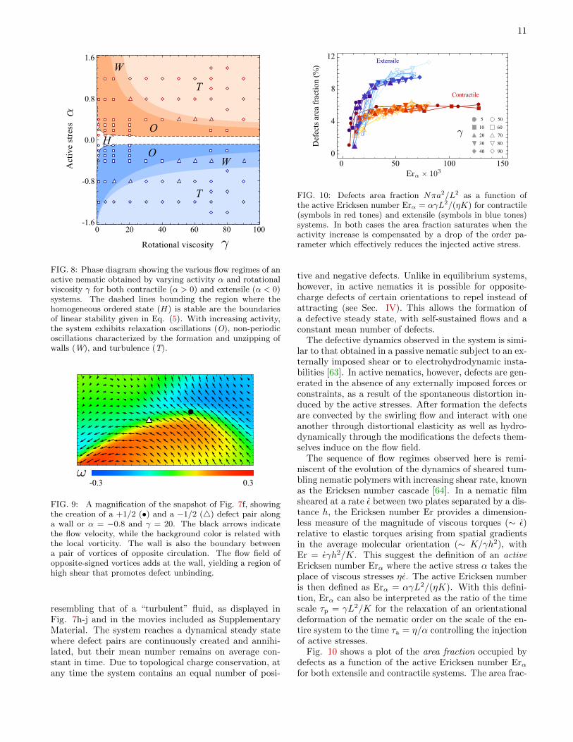
ergy and the high shear stresses present in these regions,where the nematic order parameter S is driven near zero.For this reason wall formation and unzipping occurs of-ten at the boundary between pairs of vortices of oppositecirculation (Fig. 9). In passive nematic liquid crystalsthe strong bending deformation that leads to the forma-tion of walls, and preceedes defect unbinding, requiresan external action, such as an applied electric field oran externally imposed shear stress [57]. In active nemat-ics, on the other hand, a similar complex spatiotemporaldynamics occurs spontaneously, driven by the local in-jection of active stresses, which are in turn balanced byspontaneous distortions and flows as described in Sec-tion II B. Wall formation and unzipping also combineshere with the oscillatory dynamics described in SectionV A to give rise to the periodic creation and annihilationof topological defects that marks the transition to theturbulent regime.
Oscillating band structures of the type observed hereare found in passive nematic fluids under externally ap-plied shear flows and are precursors to rheochaos [58, 59].They have been predicted theoretically [60] and observedexperimentally [61] in suspensions of wormlike micelles,where the spatiotemporal dynamics is directly correlatedto shear banding [62] and to stress/shear fluctuations atthe shear band interface. In passive systems it has beenargued that the route to rheochaos depends on whetherthe stress or the strain rate is controlled during the exper-iment. It would be interesting to analyze in more detailthe route to chaos in this case.
C. Turbulence
At even higher activity the bands/walls structure be-gins to bend and fold and the dynamics becomes chaotic,
11
FIG. 8: Phase diagram showing the various flow regimes of anactive nematic obtained by varying activity α and rotationalviscosity γ for both contractile (α > 0) and extensile (α < 0)systems. The dashed lines bounding the region where thehomogeneous ordered state (H) is stable are the boundariesof linear stability given in Eq. (5). With increasing activity,the system exhibits relaxation oscillations (O), non-periodicoscillations characterized by the formation and unzipping ofwalls (W), and turbulence (T).
FIG. 9: A magnification of the snapshot of Fig. 7f, showingthe creation of a +1/2 (•) and a −1/2 (4) defect pair alonga wall or α = −0.8 and γ = 20. The black arrows indicatethe flow velocity, while the background color is related withthe local vorticity. The wall is also the boundary betweena pair of vortices of opposite circulation. The flow field ofopposite-signed vortices adds at the wall, yielding a region ofhigh shear that promotes defect unbinding.
resembling that of a “turbulent” fluid, as displayed inFig. 7h-j and in the movies included as SupplementaryMaterial. The system reaches a dynamical steady statewhere defect pairs are continuously created and annihi-lated, but their mean number remains on average con-stant in time. Due to topological charge conservation, atany time the system contains an equal number of posi-
FIG. 10: Defects area fraction Nπa2/L2 as a function ofthe active Ericksen number Erα = αγL2/(ηK) for contractile(symbols in red tones) and extensile (symbols in blue tones)systems. In both cases the area fraction saturates when theactivity increase is compensated by a drop of the order pa-rameter which effectively reduces the injected active stress.
tive and negative defects. Unlike in equilibrium systems,however, in active nematics it is possible for opposite-charge defects of certain orientations to repel instead ofattracting (see Sec. IV). This allows the formation ofa defective steady state, with self-sustained flows and aconstant mean number of defects.
The defective dynamics observed in the system is simi-lar to that obtained in a passive nematic subject to an ex-ternally imposed shear or to electrohydrodynamic insta-bilities [63]. In active nematics, however, defects are gen-erated in the absence of any externally imposed forces orconstraints, as a result of the spontaneous distortion in-duced by the active stresses. After formation the defectsare convected by the swirling flow and interact with oneanother through distortional elasticity as well as hydro-dynamically through the modifications the defects them-selves induce on the flow field.
The sequence of flow regimes observed here is remi-niscent of the evolution of the dynamics of sheared tum-bling nematic polymers with increasing shear rate, knownas the Ericksen number cascade [64]. In a nematic filmsheared at a rate ε between two plates separated by a dis-tance h, the Ericksen number Er provides a dimension-less measure of the magnitude of viscous torques (∼ ε)relative to elastic torques arising from spatial gradientsin the average molecular orientation (∼ K/γh2), withEr = εγh2/K. This suggest the definition of an activeEricksen number Erα where the active stress α takes theplace of viscous stresses ηε. The active Ericksen numberis then defined as Erα = αγL2/(ηK). With this defini-tion, Erα can also be interpreted as the ratio of the timescale τp = γL2/K for the relaxation of an orientationaldeformation of the nematic order on the scale of the en-tire system to the time τa = η/α controlling the injectionof active stresses.
Fig. 10 shows a plot of the area fraction occupied bydefects as a function of the active Ericksen number Erαfor both extensile and contractile systems. The area frac-

12
tion is defined as the relative area occupied by the coreof the defects, or Nπa2/L2, with N the number of de-fects. The core radius a resulting from the hydrodynamicequations (1) is approximatively given by the size of theboundary layer between the position of a defect, whereS = 0, and surrounding space, where S = S0. This is pro-portional to the coefficient A in the Landau-de Gennesfree energy (2)
a =
√K
|A|≈ 1√
|c0 − c∗|≈ ` . (28)
For larger activity the reduction of the nematic orderparameter due to the unbound defects compensates theactivity increase by effectively reducing the injected localstress σa ≈ αS.
For the same magnitude of activity, extensile systemscontain a larger mean number of defects than contractileones. In both case defect pairs first unbind within thewalls, which are regions of large bend and splay defor-mations in extensile and contractile systems, respectively.As the system evolves toward the regime of chaotic dy-namics, the walls begin to deform largely via bend defor-mations in both systems [15, 16]. This asymmetry couldbe because the severe splay deformations localized at thewalls lead to a more drastic reduction of the nematic or-der parameter. Thus contractile flow-tumbling nematics,whose spontaneous distortion involves mostly splay de-formations, are effectively less active than flow-tumblingextensile systems.
VI. DISCUSSION AND CONCLUSIONS
We have presented a detailed analytical and numericalstudy of the mechanics of topological defects in active ne-matic liquid crystals. Topological defects are distinctivesignatures of liquid crystals and profoundly affect theirviscoelastic behavior by constraining the orientationalstructure of the fluid in a way that inevitably requiressystem-wide (global) changes not achievable with any setof local deformations. In ordered states of both passiveand active nematics, the topological defects are finger-prints of the broken symmetry in the ordered state. Inparticular, the presence of strength ±1/2 defects clearlyreveals the nematic nature of the orientational order, incontrast to systems with polar (ferromagnetic) symme-try where the lowest energy defects allowed have strength±1. Active liquid crystals have the additional featurethat defects act as local sources of motion, behaving asself-propelled particle-like objects (see Sec. III). The di-rection of motion of the strength +1/2 defects provides,furthermore, a clear signature of the extensile or contrac-tile nature of the active stresses, as the comet-like posi-tive defects are advected towards their head in extensilesystems and towards their tail in contractile ones. In pas-
sive liquid crystals defect dynamics is always transient, asoppositely charged defects attract and eventually annihi-late. In active nematics, on the other hand, the interplaybetween active and viscous stresses, modulated by thedirector geometry induced by the defects, enriches thespectrum of defect-defect interactions by allowing for aneffective repulsion between defects and anti-defects (seeSec. IV). For highly active systems this mechanism canarrest the process of coarsening, leading to a state whereunbound pairs of defects are continuously created and an-nihilated, but with their mean density constant in time(see Sec. V). The chaotic dynamics originating from thecontinuous defect proliferation and annihilation resultsin spontaneous low Reynolds number turbulence, akin tothe so-called director turbulence seen in sheared polymerand micellar nematics [64].
Several open questions remain concerning the defectdynamics of active nematics. The defect area fractionshown in Fig. 10 exhibits a crossover from growth at lowactivity to saturation at high activity, but an understand-ing of the length scales that control this behavior is stilllacking. Both our work and work by Thampi et al. [16]suggest that the mean separation between defects in theturbulent regime coincides with the typical vortex size,but more work is needed to elucidate the behavior of thislength scale with activity over a wide range of param-eters. While defect generation in sheared nematics hasbeen explained in terms of a simple rate equation thatbalances creation and annihilation [64], a similar simplemodel for active defects is still missing. On the basis ofnumerics, Thampi et al. have suggested that the defectcreation rate should scale like the square of the activ-ity [16], but no simple argument is available to under-stand this counterintuitive result. Finally, an importantopen question is the different behavior of extensile andcontractile systems apparent from Fig. 10. The turbulentstate of contractile systems is much less defective thanthat of extensile ones, suggesting that for equal magni-tude of the activity α, contractile nematics are effectively“less active” than extensile ones.
Acknowledgments
We thank Zvonimir Dogic, Suzanne Fielding, Jean-Francois Joanny, Oleg Lavrentovich, and Tim Sanchez forseveral illuminating discussions. LG was supported bySISSA mathLab. The work at Syracuse was supported bythe National Science Foundation through awards DMR-1305184 (MCM, PM) and DGE-1068780 (MCM) and byfunds from the Syracuse Soft Matter Program. MCMalso acknowledges support from the Simons Foundation.Finally, MCM and MJB thank the KITP at the Univer-sity of California, Santa Barbara, for support during thepreparation of the manuscript.

13
Appendix A: Active backflow of +1/2 disclinations
Finding the backflow produced by the positive disclination reduces to the calculation of the following integrals:
I1 =
∫dA′
1
r′
(log
L|r − r′|
− 1
), (A1a)
I2 =
∫dA′
1
r′(ri − r′i)(x− x′)|r − r′|2
. (A1b)
To calculate the first integral, we can make use of the logarithmic expansion
log|r − r′|L
= log(r>L
)−∞∑n=1
1
n
(r<r>
)ncos[n(φ− φ′)] , (A2)
where r> = max(|r|, |r′|) and r< = min(|r|, |r′|). The integral over the angle can be immediately carried out using
the orthogonality of trigonometric functions:∫ 2π
0dφ′ cos[n(φ− φ′)] = δn0. The remaining radial integral can be then
straightforwardly calculated: ∫dr′ log
(r>L
)= r −R+R log
(R
L
). (A3)
Thus:
I1 = −2π
[r +R log
(R
L
)].
To calculate the integral I2, we can make use of the fact that
ri − r′i|r − r′|2
=∂
∂rilog |r − r′| . (A4)
Thus one can write
I2 = x∂
∂ri
∫dr′ dφ′ log |r − r′| − ∂
∂ri
∫dr′ dφ′ x′ log |r − r′| . (A5)
The first integral is calculated by differentiating I1:
x∂
∂ri
∫dr′ dφ log |r − r′| = 2πxri
r. (A6)
The second integral in Eq. (A5) can be calculated again with the help of the logarithmic expansion (A2):∫dr′ dφ′ r cosφ′ log |r − r′| = −π cosφ
∫ R
0
dr′ r′r<r>
= −πr cosφ
(R− 2
3r
), (A7)
where we have used again the orthogonality of trigonometric functions:∫ 2π
0
dφ′ cosn(φ− φ′) cosmφ′ = π cosmφδnm . (A8)
Thus, taking the derivative and combining with Eq. (A6), yields:
I2 =4π
3
xrir
+ π
(R− 2
3r
)δix . (A9)
Adding together I1 and I2 and switching to polar coordinates gives:
vx =α
12η
{[3
(3R
2+ 3R log
LR− r)
+ r cos 2φ
]}, (A10a)
vy =α
12ηr sin 2φ . (A10b)
Setting L = R√e and expressing everything in polar coordinates one finally gets Eq. (15a).

14
Appendix B: Active backflow of −1/2 disclinations
The calculation of the active backflow associated with a negative disclination reduces to the calculation of thefollowing integrals:
I3 =
∫dA′
1
r′
(log
L|r − r′|
− 1
)[sin 2φ′ y − cos 2φ′ x] , (B1)
I4 =
∫dA′
1
r′ri − r′i|r − r′|2
[(y − y′) sin 2φ′ − (x− x′) cos 2φ′] . (B2)
The first integral can be calculated with the help of the logarithmic expansion (A2) as well as the orthogonalitycondition (A8). This yields:
I3 =1
2πr
(4
3− r
R
)(sin 2φ y − cos 2φx) . (B3)
To calculate I4 we can use again Eq. (A4). Thus:
I4 = y∂
∂ri
∫dr′dφ′ log |r − r′| sin 2φ′ − ∂
∂ri
∫dr′dφ′ log |r − r′| y′ sin 2φ′
− x ∂
∂ri
∫dr′dφ′ log |r − r′| cos 2φ′ +
∂
∂ri
∫dr′dφ′ log |r − r′|x′ cos 2φ′ . (B4)
The first and third integral in Eq. (B4) are respectively the opposite of the y− and x−component of I3. The remainingtwo integrals, can be calculated using Eq. (A2) and (A8). This gives:∫
dr′dφ′ log |r − r′| f±(r′, φ′) = −π2
[r
(R− 2
3r
)cosφ± 1
3r2(
6
5− r
R
)cos 3φ
], (B5)
where f+(r′, φ′) = x′ cos 2φ′ and f−(r′, φ′) = y′ sin 2φ′. Combining I3 and I4 and switching to polar coordinatesfinally gives Eq. (15b).
[1] Marchetti MC, Joanny JF, Ramaswamy S, LiverpoolTB, Prost J, Rao M, Simha RA. 2013 Hydrodynam-ics of soft active matter. Rev. Mod. Phys. 85, 11431189[arXiv:1207.2929].
[2] Voituriez R, Joanny JF, Prost J. 2005 Spontaneous flowtransition in active polar gels. Europhys. Lett. 70, 404410[arXiv:q-bio/0503022v1].
[3] Marenduzzo D, Orlandini E, Cates ME, Yeomans JM.2007 Steady-state hydrodynamic instabilities of activeliquid crystals: Hybrid lattice Boltzmann simulations.Phys. Rev. E 76, 031921 [arXiv:0708.2062].
[4] Giomi L, Marchetti MC, Liverpool TB. 2008 Complexspontaneous flow and concentration banding in active po-lar films. Phys. Rev. Lett. 101, 198101 [arXiv:0805.1680].
[5] Ramaswamy S, Simha RA, Toner J. 2003 Active ne-matics on a substrate: giant number fluctuations andlong-time tails. Europhys. Lett. 62, 196202 [arXiv:cond-mat/0208573].
[6] Mishra S, Ramaswamy S. 2006 Active nematics are in-trinsically phase separated. Phys. Rev. Lett. 97, 090602[arXiv:cond-mat/0603051].
[7] Narayan V, Ramaswamy S, Menon N. 2007 Long-lived gi-
ant number fluctuations in a swarming granular nematic.Science 317 , 105-108 [arXiv:cond-mat/0612020].
[8] Sokolov A, Aranson IS. 2009 Reduction of viscosity insuspension of swimming bacteria. Phys. Rev. Lett. 103,148101.
[9] Giomi L, Liverpool TB, Marchetti MC. 2010 Sheared ac-tive fluids: Thickening, thinning, and vanishing viscosity.Phys. Rev. E 81, 051908 [arXiv:1002.0517].
[10] Fielding SM, Marenduzzo D, Cates ME. 2011 Non-linear dynamics and rheology of active fluids: Simu-lations in two dimensions. Phys. Rev. E 83, 041910[arXiv:1012.3233].
[11] Giomi L, Mahadevan L, Chakraborty B, Hagan MF. 2011Excitable patterns in active nematics Phys. Rev. Lett.106, 218101 [arXiv:1011.3841].
[12] Giomi L, Mahadevan L, Chakraborty B, Hagan MF. 2012Banding, excitability and chaos in active nematic suspen-sions. Nonlinearity 25, 2245-2269 [arXiv:1110.4338].
[13] Wensink HH, Dunkel J, Heidenreich S, Drescher K, Gold-stein RE, Lowen H, Yeomans JM. 2012 Meso-scale tur-bulence in living fluids. Proc. Natl. Acad. Sci. USA 109,14308-14313 [arXiv:1208.4239].
15
[14] Thampi SP, Golestanian R, Yeomans JM. 2013 Velocitycorrelations in an active nematic Phys. Rev. Lett. 111,118101 [arXiv:1302.6732].
[15] Thampi SP, Golestanian R, Yeomans JM. 2014 Instabili-ties and topological defects in active nematics. Europhys.Lett. 105, 18001 [arXiv:1312.4836].
[16] Thampi SP, Golestanian R, Yeomans JM. 2014 Vor-ticity, defects and correlations in active turbulence[arXiv:1402.0715].
[17] Gao T, Blackwell R, Glaser MA, Betterton MD, Shel-ley MJ. 2014 A multiscale active nematic theory ofmicrotubule/motor-protein assemblies [arXiv:1401.8059].
[18] Kemkemer R, Kling D, Kaufmann D, Gruler HH. 2000Elastic properties of nematoid arrangements formed byamoeboid cells. Eur. Phys. J. E 1, 215-225.
[19] Duclos G, Garcia S, Yevick HG, Silberzan P. 2014 Perfectnematic order in confined monolayers of spindle-shapedcells. Soft Matter DOI: 10.1039/C3SM52323C.
[20] Ezhilan B, Shelley MJ, Saintillan D. 2013 Instabilities,pattern formation, and mixing in active suspensions.Phys. Fluids 25, 123304.
[21] Sanchez T, Chen DN, DeCamp SJ, Heymann M, DogicZ. 2012 Spontaneous motion in hierarchically assembledactive matter. Nature 491, 431-434 [arXiv:1301.1122].
[22] Zhou S, Sokolov A, Lavrentovich OD, Aranson IS. 2014Living liquid crystals. Proc. Nat. Acad. Sci. U.S.A. 111,1265-1270 [arXiv:1312.5359].
[23] Elgeti J, Cates ME, Marenduzzo D. 2011 Defect hydro-dynamics in 2D polar active fluids. Soft Matter 7, 3177-3185.
[24] Giomi L, Bowick MJ, Ma X, Marchetti MC. 2013 Defectannihilation and proliferation in active nematics. Phys.Rev. Lett. 110, 228101 [arXiv:1303.4720]. Erratum: De-fect annihilation and proliferation in active nematics.Phys. Rev. Lett. 111, 209901.
[25] Kleman M, Lavrentovich O. 2006 Topological point de-fects in nematic liquid crystals. Phil. Mag. 86, 4117-4137.
[26] Kleman M, Lavrentovich O. 2003 Soft Matter Physics:An Introduction. New York: Springer.
[27] Lavrentovich O. 1998 Topological defects in dispersed liq-uid crystals, or words and worlds around liquid crystaldrops. Liq. Cryst. 24, 117-125.
[28] de Gennes PG, Prost J. 1993 The Physics of Liquid Crys-tals: 2nd edn. Oxford: Oxford University Press.
[29] Nedelec F, Surrey T, Maggs AC, Leibler S. 1997 Self-organization of microtubules and motors. Nature 389,305-308.
[30] Surrey T, Nedelec F, Leibler S, Karsenti E. 2001 Physicalproperties determining self-organization of motors andmicrotubules Science 292, 1167-1171.
[31] Voituriez R, Joanny JF, Prost J. 2006 Generic phase di-agram of active polar film. Phys. Rev. Lett. 96, 028102[arXiv:0807.0275].
[32] Kruse K, Joanny JF, Julicher F, Prost J, Sekimoto K.2004 Asters, vortices, and rotating spirals in active gelsof polar filaments. Phys. Rev. Lett. 92, 078101.
[33] Kruse K, Julicher F. 2006 Dynamics and mechanics ofmotor-filament systems. Eur. Phys. J. E 20, 459-465.
[34] Pismen LM. 2013 Dynamics of defects in an ac-tive nematic layer. Phys. Rev. E 88, 050502(R)[arXiv:1308.3364].
[35] Liverpool TB, Marchetti MC. 2008 Hydrodynamics andrheology of active polar filaments. in Cell Motility, P.Lenz editor, 177-206 (Springer, New York) [arXiv:q-
bio/0703029].[36] Kruse K, Joanny JF, Julicher F, Prost J., Sekimoto K.
2005 Generic theory of active polar gels: a paradigmfor cytoskeletal dynamics Eur. Phys. J. E 16, 5-16[arXiv:physics/0406058].
[37] Joanny JF, Julicher F, Kruse K, Prost J. 2007 Hydrody-namic theory for multi-component active polar gels NewJ. Phys. 9, 422.
[38] Liverpool TB, Marchetti MC. 2003 Instabilities ofisotropic solutions of active polar filaments. Phys. Rev.Lett 90, 138102 [arXiv:cond-mat/0207320].
[39] Liverpool TB, Marchetti MC. 2005 Bridging the micro-scopic and the hydrodynamic in active filament solutions.Europhys. Lett. 69,846-852 [arXiv:cond-mat/0406276].
[40] Edwards SA, Yeomans JM. 2009 Spontaneous flow statesin active nematics: a unified picture. Europhys. Lett. 85,18008 [arXiv:0811.3432].
[41] Bray AJ. 2002 Theory of phase-ordering kinetics. Adv.Phys. 51, 481-587 [arXiv:cond-mat/9501089].
[42] Chuang I, Yurke B, Pargellis AN, Turok N. 1993 Coars-ening dynamics in uniaxial nematic liquid crystals. Phys.Rev. E 47, 3343-3356.
[43] Denniston C. 1996 Disclination dynamics in nematic liq-uid crystals. Phys. Rev. B 54, 6272-6275.
[44] Pleiner H. 1988 Dynamics of a disclination point insmectic-C and -C∗ liquid-crystal films. Phys. Rev. A 37,3986-3992.
[45] Ryskin G, Kremenetsky M. 1991 Drag force on a linedefect moving through an otherwise undisturbed field:Disclination line in a nematic liquid crystal. Phys. Rev.Lett. 67, 1574-1577.
[46] Kats EI, Lebedev VV, Malinin SV. 2002 Disclination mo-tion in liquid crystalline films. J. Exp. Theor. Phys. 95,714-727 [arXiv:cond-mat/0205247v1].
[47] Di Leonardo R, Keen S, Ianni F, Leach J, Padgett MJ,Ruocco G. 2008 Hydrodynamic interactions in two di-mensions. Phys. Rev. E 78, 031406 [arXiv:0804.0850].
[48] Shi X, Ma Y. 2013 Topological structure dynamics reveal-ing collective evolution in active nematics. Nat. Commun.4, 3013.
[49] Lamb H. 1945 Hydrodynamics, 6th edn. New York: DoverPublications.
[50] Lubensky DK, Goldstein RE. 1996 Hydrodynamics ofmonolayer domains at the air-water interface. Phys. Flu-ids 8, 843-854 [arXiv:patt-sol/9602002].
[51] Toth G, Denniston C, Yeomans JM. 2002 Hydrodynam-ics of topological defects in nematic liquid crystals. Phys.Rev. Lett. 88, 105504 [arXiv:cond-mat/0201378].
[52] Bogi A, Martinot-Lagarde P, Dozov I, Nobili M. 2002Anchoring screening of defects interaction in a nematicliquid crystal. Phys. Rev. Lett. 89, 225501.
[53] D. Svensek and S. Zumer 2002 Hydrodynamics of pair-annihilating disclination lines in nematic liquid crystals.Phys. Rev. E 66, 021712.
[54] Sonnet AM, Virga EG. 2009 Flow and reorientation inthe dynamics of nematic defects. Liq. Cryst. 36, 1185-1192.
[55] Dierking I, Ravnik M, Lark E, Healey J, Alexander GP,Yeomans JM. 2012 Anisotropy in the annihilation dy-namics of umbilic defects in nematic liquid crystals. Phys.Rev. E 85, 021703.
[56] Helfrich W, 1968 Alignment-inversion walls in nematicliquid crystals in the presence of a magnetic field, Phys.Rev. Lett. 21, 1518-1521.

16
[57] de Lozar A, Schopf W, Rehberg I, Svensek D, KramerL. 2005 Transformation from walls to disclination lines:Statics and dynamics of the pincement transition. Phys.Rev. E 72, 051713.
[58] Chakrabarti B, Das M, Dasgupta C, Ramaswamy S,Sood AK. 2004 Spatiotemporal rheochaos in nematic hy-drodynamics. Phys. Rev. Lett. 92, 055501 [arXiv:cond-mat/0311101].
[59] Chakraborty D, Dasgupta C, Sood AK. 2010 Bandedspatiotemporal chaos in sheared nematogenic fluids.Phys. Rev. E 82, 065301(R) [arXiv:1002.0213v1].
[60] Fielding SM, Olmsted PD. 2004 Spatiotemporal os-cillations and rheochaos in a simple model of shear
banding. Phys. Rev. Lett. 92, 084502 [arXiv:cond-mat/0310658v1].
[61] Ganapathy A, Majumdar R, Sood AK. 2008 Spatiotem-poral dynamics of shear induced bands en route torheochaos. Eur. Phys. J. B 64, 537-542.
[62] Olmsted PD. 2008 Perspectives on shear banding in com-plex fluids Rheol. Acta 47, 283-300.
[63] Manneville P. 1981 The transition to turbulence in ne-matic liquid crystals. Mol. Cryst. Liq. Cryst. 70, 223-250.
[64] Larson RG, Mead DW. 1993 The Ericksen number andDeborah number cascades in sheared polymeric nematics.Liq. Cryst. 15, 151-169.