Characterization of synchronization in a unidirectionally coupled system of nonlinear...
9
Sensors and Actuators A 171 (2011) 361–369 Contents lists available at SciVerse ScienceDirect Sensors and Actuators A: Physical jo u rn al hom epage: www.elsevier.com/locate/sna Characterization of synchronization in a unidirectionally coupled system of nonlinear micromechanical resonators Suketu Naik a,∗ , Takashi Hikihara a , Antonio Palacios b , Visarath In c , Huy Vu b , Patrick Longhini c a Department of Electrical Engineering, Kyoto University, Katsura, Nishikyo, Kyoto 615-8510, Japan b Nonlinear Dynamical Systems Group, Department of Mathematics, San Diego State University, San Diego, CA 92182, USA c Space and Naval Warfare Systems Center Pacific, Code 71730, 53560 Hull St, San Diego, CA 92152-5001, USA a r t i c l e i n f o Article history: Received 15 June 2011 Received in revised form 24 August 2011 Accepted 30 August 2011 Available online 7 September 2011 Keywords: Coupled MEMS resonators Hard spring effect Hysteresis Synchronization Electrostatic actuator a b s t r a c t In this paper the experimental results of synchronization in an electronically coupled system of micro electro mechanical system (MEMS) resonators with hysteresis in frequency-domain are entailed. First the hysteretic responses of the individual MEMS resonators are characterized by changing the excitation voltage. These resonators are then interconnected in a ring of unidirectionally coupled system. The cou- pled system is shown to exhibit oscillations in the self-excited mode while changing the coupling strength past a threshold value. In the presence of the ac excitation signal, the coupled system is shown to exhibit the stable and unstable behaviors that lead to regions of synchronization. Sensitivity with regards to the coupling strength, excitation frequency and excitation amplitude is also shown in the experiments. These behavior characteristics of the coupled system will naturally be harnessed to be used as a sensor. © 2011 Elsevier B.V. All rights reserved. 1. Introduction In modern signal processing systems MEMS resonators are becoming ubiquitous and are being used increasingly as parts of sensor systems, reference clocks, memory elements, and filters [1,2]. MEMS devices are normally targeted to achieve a specific range within its linear mode of operation. At a higher vibration amplitude, the devices may exhibit a nonlinear response [3]. The causes of nonlinearity in MEMS include material anisotropicity in a nonuniform material, large vibrations, variation in individ- ual structure elements during fabrication, circuit elements, and/or a combination of all of the above. In particular the hard-spring effect in electrostatically excited fixed-fixed beam resonator and comb-drive resonator has already been reported in MEMS research [4–6]. The nonlinear oscillations in MEMS devices have found their usage in many applications. In Wang et al. [7] chaotic vibrations were investigated in a nonlinear MEMS oscillator by using two actuators and the device was demonstrated in a secure communi- cation experiment. Coupled MEMS resonators and oscillators can offer additional advantages such as pattern forming and signal pro- cessing by the virtue of nonlinear phase-locking as was shown ∗ Corresponding author. E-mail addresses: [email protected] (S. Naik), [email protected] (T. Hikihara), [email protected] (A. Palacios), [email protected] (V. In), [email protected] (H. Vu), [email protected] (P. Longhini). in Hoppensteadt and Izhikevich [8]. Mechanically coupled mul- tiple comb-drives can be utilized to provide a wider drive-mode bandwidth and to increase the robustness of the gyroscopes while operating them in the linear range [9]. In Wang and Nguyen [10] a mechanically coupled system of three high-Q MEMS resonators was configured in an open loop as a bandpass filter with the cen- ter frequency of 340 kHz and very low insertion loss. In Chivukula and Rhoads [11] the open loop and closed loop chains of beam resonators were compared in a detailed simulation study and it was observed that the closed loop chains offered excellent pass- band rejection, symmetric frequency response and robustness to process-induced variations. In the experimental study shown in Shim et al. [12], synchronization in two beam resonators coupled via a beam was realized and the coupled system demonstrated rich dynamical behavior leading to a number of synchronization regions. In Bucks and Roukes [13] an opto-mechanical system of a grating array with a large number of doubly clamped beams was electrostatically actuated which induced mechanical coupling and a wide range of vibrational modes. A plethora of the devices and results reported above indicate that the coupled MEMS devices can exhibit many intriguing behaviors. Rings of coupled analog oscillators have also been reported which show the appearance of periodic rotating waves in the chaotic Lorenz oscillators [14] and a route to chaotic oscillations through quasiperiodicity [15]. Coupling induced oscillations have been shown to be very sensi- tive when a target signal is present [16,17] and mutual coupling between two coupled arrays can even lead to multiple frequen- cies in the self-excited mode [18]. Furthermore in Vu et al. [19] a 0924-4247/$ – see front matter © 2011 Elsevier B.V. All rights reserved. doi:10.1016/j.sna.2011.08.026
Transcript of Characterization of synchronization in a unidirectionally coupled system of nonlinear...

Cn
Sa
b
c
a
ARRAA
KCHHSE
1
bs[raciuaec[uwacoc
h(p
0d
Sensors and Actuators A 171 (2011) 361– 369
Contents lists available at SciVerse ScienceDirect
Sensors and Actuators A: Physical
jo u rn al hom epage: www.elsev ier .com/ locate /sna
haracterization of synchronization in a unidirectionally coupled system ofonlinear micromechanical resonators
uketu Naika,∗, Takashi Hikiharaa, Antonio Palaciosb, Visarath Inc, Huy Vub, Patrick Longhini c
Department of Electrical Engineering, Kyoto University, Katsura, Nishikyo, Kyoto 615-8510, JapanNonlinear Dynamical Systems Group, Department of Mathematics, San Diego State University, San Diego, CA 92182, USASpace and Naval Warfare Systems Center Pacific, Code 71730, 53560 Hull St, San Diego, CA 92152-5001, USA
r t i c l e i n f o
rticle history:eceived 15 June 2011eceived in revised form 24 August 2011ccepted 30 August 2011vailable online 7 September 2011
a b s t r a c t
In this paper the experimental results of synchronization in an electronically coupled system of microelectro mechanical system (MEMS) resonators with hysteresis in frequency-domain are entailed. Firstthe hysteretic responses of the individual MEMS resonators are characterized by changing the excitationvoltage. These resonators are then interconnected in a ring of unidirectionally coupled system. The cou-pled system is shown to exhibit oscillations in the self-excited mode while changing the coupling strength
eywords:oupled MEMS resonatorsard spring effectysteresis
past a threshold value. In the presence of the ac excitation signal, the coupled system is shown to exhibitthe stable and unstable behaviors that lead to regions of synchronization. Sensitivity with regards to thecoupling strength, excitation frequency and excitation amplitude is also shown in the experiments. Thesebehavior characteristics of the coupled system will naturally be harnessed to be used as a sensor.
ynchronizationlectrostatic actuator
. Introduction
In modern signal processing systems MEMS resonators areecoming ubiquitous and are being used increasingly as parts ofensor systems, reference clocks, memory elements, and filters1,2]. MEMS devices are normally targeted to achieve a specificange within its linear mode of operation. At a higher vibrationmplitude, the devices may exhibit a nonlinear response [3]. Theauses of nonlinearity in MEMS include material anisotropicityn a nonuniform material, large vibrations, variation in individ-al structure elements during fabrication, circuit elements, and/or
combination of all of the above. In particular the hard-springffect in electrostatically excited fixed-fixed beam resonator andomb-drive resonator has already been reported in MEMS research4–6]. The nonlinear oscillations in MEMS devices have found theirsage in many applications. In Wang et al. [7] chaotic vibrationsere investigated in a nonlinear MEMS oscillator by using two
ctuators and the device was demonstrated in a secure communi-
ation experiment. Coupled MEMS resonators and oscillators canffer additional advantages such as pattern forming and signal pro-essing by the virtue of nonlinear phase-locking as was shown∗ Corresponding author.E-mail addresses: [email protected] (S. Naik),
[email protected] (T. Hikihara), [email protected]. Palacios), [email protected] (V. In), [email protected] (H. Vu),[email protected] (P. Longhini).
924-4247/$ – see front matter © 2011 Elsevier B.V. All rights reserved.oi:10.1016/j.sna.2011.08.026
© 2011 Elsevier B.V. All rights reserved.
in Hoppensteadt and Izhikevich [8]. Mechanically coupled mul-tiple comb-drives can be utilized to provide a wider drive-modebandwidth and to increase the robustness of the gyroscopes whileoperating them in the linear range [9]. In Wang and Nguyen [10]a mechanically coupled system of three high-Q MEMS resonatorswas configured in an open loop as a bandpass filter with the cen-ter frequency of 340 kHz and very low insertion loss. In Chivukulaand Rhoads [11] the open loop and closed loop chains of beamresonators were compared in a detailed simulation study and itwas observed that the closed loop chains offered excellent pass-band rejection, symmetric frequency response and robustness toprocess-induced variations. In the experimental study shown inShim et al. [12], synchronization in two beam resonators coupledvia a beam was realized and the coupled system demonstratedrich dynamical behavior leading to a number of synchronizationregions. In Bucks and Roukes [13] an opto-mechanical system of agrating array with a large number of doubly clamped beams waselectrostatically actuated which induced mechanical coupling anda wide range of vibrational modes. A plethora of the devices andresults reported above indicate that the coupled MEMS devicescan exhibit many intriguing behaviors. Rings of coupled analogoscillators have also been reported which show the appearanceof periodic rotating waves in the chaotic Lorenz oscillators [14]and a route to chaotic oscillations through quasiperiodicity [15].
Coupling induced oscillations have been shown to be very sensi-tive when a target signal is present [16,17] and mutual couplingbetween two coupled arrays can even lead to multiple frequen-cies in the self-excited mode [18]. Furthermore in Vu et al. [19] a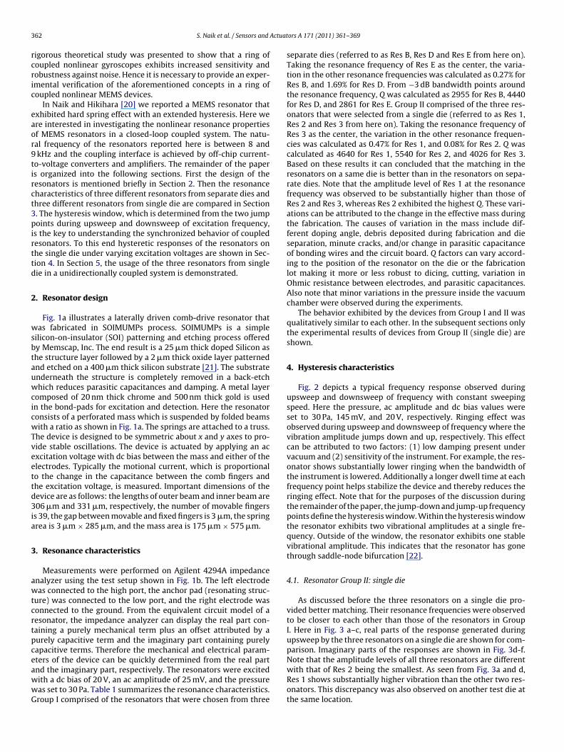
3 Actuat
rcric
eaor9tirct3pirttd
2
wsbtauwcicwTveettd3ia
3
awtcrtpceawwG
62 S. Naik et al. / Sensors and
igorous theoretical study was presented to show that a ring ofoupled nonlinear gyroscopes exhibits increased sensitivity andobustness against noise. Hence it is necessary to provide an exper-mental verification of the aforementioned concepts in a ring ofoupled nonlinear MEMS devices.
In Naik and Hikihara [20] we reported a MEMS resonator thatxhibited hard spring effect with an extended hysteresis. Here were interested in investigating the nonlinear resonance propertiesf MEMS resonators in a closed-loop coupled system. The natu-al frequency of the resonators reported here is between 8 and
kHz and the coupling interface is achieved by off-chip current-o-voltage converters and amplifiers. The remainder of the papers organized into the following sections. First the design of theesonators is mentioned briefly in Section 2. Then the resonanceharacteristics of three different resonators from separate dies andhree different resonators from single die are compared in Section. The hysteresis window, which is determined from the two jumpoints during upsweep and downsweep of excitation frequency,
s the key to understanding the synchronized behavior of coupledesonators. To this end hysteretic responses of the resonators onhe single die under varying excitation voltages are shown in Sec-ion 4. In Section 5, the usage of the three resonators from singleie in a unidirectionally coupled system is demonstrated.
. Resonator design
Fig. 1a illustrates a laterally driven comb-drive resonator thatas fabricated in SOIMUMPs process. SOIMUMPs is a simple
ilicon-on-insulator (SOI) patterning and etching process offeredy Memscap, Inc. The end result is a 25 �m thick doped Silicon ashe structure layer followed by a 2 �m thick oxide layer patternednd etched on a 400 �m thick silicon substrate [21]. The substratenderneath the structure is completely removed in a back-etchhich reduces parasitic capacitances and damping. A metal layer
omposed of 20 nm thick chrome and 500 nm thick gold is usedn the bond-pads for excitation and detection. Here the resonatoronsists of a perforated mass which is suspended by folded beamsith a ratio as shown in Fig. 1a. The springs are attached to a truss.
he device is designed to be symmetric about x and y axes to pro-ide stable oscillations. The device is actuated by applying an acxcitation voltage with dc bias between the mass and either of thelectrodes. Typically the motional current, which is proportionalo the change in the capacitance between the comb fingers andhe excitation voltage, is measured. Important dimensions of theevice are as follows: the lengths of outer beam and inner beam are06 �m and 331 �m, respectively, the number of movable fingers
s 39, the gap between movable and fixed fingers is 3 �m, the springrea is 3 �m × 285 �m, and the mass area is 175 �m × 575 �m.
. Resonance characteristics
Measurements were performed on Agilent 4294A impedancenalyzer using the test setup shown in Fig. 1b. The left electrodeas connected to the high port, the anchor pad (resonating struc-
ure) was connected to the low port, and the right electrode wasonnected to the ground. From the equivalent circuit model of aesonator, the impedance analyzer can display the real part con-aining a purely mechanical term plus an offset attributed by aurely capacitive term and the imaginary part containing purelyapacitive terms. Therefore the mechanical and electrical param-ters of the device can be quickly determined from the real part
nd the imaginary part, respectively. The resonators were excitedith a dc bias of 20 V, an ac amplitude of 25 mV, and the pressureas set to 30 Pa. Table 1 summarizes the resonance characteristics.roup I comprised of the resonators that were chosen from threeors A 171 (2011) 361– 369
separate dies (referred to as Res B, Res D and Res E from here on).Taking the resonance frequency of Res E as the center, the varia-tion in the other resonance frequencies was calculated as 0.27% forRes B, and 1.69% for Res D. From −3 dB bandwidth points aroundthe resonance frequency, Q was calculated as 2955 for Res B, 4440for Res D, and 2861 for Res E. Group II comprised of the three res-onators that were selected from a single die (referred to as Res 1,Res 2 and Res 3 from here on). Taking the resonance frequency ofRes 3 as the center, the variation in the other resonance frequen-cies was calculated as 0.47% for Res 1, and 0.08% for Res 2. Q wascalculated as 4640 for Res 1, 5540 for Res 2, and 4026 for Res 3.Based on these results it can concluded that the matching in theresonators on a same die is better than in the resonators on sepa-rate dies. Note that the amplitude level of Res 1 at the resonancefrequency was observed to be substantially higher than those ofRes 2 and Res 3, whereas Res 2 exhibited the highest Q. These vari-ations can be attributed to the change in the effective mass duringthe fabrication. The causes of variation in the mass include dif-ferent doping angle, debris deposited during fabrication and dieseparation, minute cracks, and/or change in parasitic capacitanceof bonding wires and the circuit board. Q factors can vary accord-ing to the position of the resonator on the die or the fabricationlot making it more or less robust to dicing, cutting, variation inOhmic resistance between electrodes, and parasitic capacitances.Also note that minor variations in the pressure inside the vacuumchamber were observed during the experiments.
The behavior exhibited by the devices from Group I and II wasqualitatively similar to each other. In the subsequent sections onlythe experimental results of devices from Group II (single die) areshown.
4. Hysteresis characteristics
Fig. 2 depicts a typical frequency response observed duringupsweep and downsweep of frequency with constant sweepingspeed. Here the pressure, ac amplitude and dc bias values wereset to 30 Pa, 145 mV, and 20 V, respectively. Ringing effect wasobserved during upsweep and downsweep of frequency where thevibration amplitude jumps down and up, respectively. This effectcan be attributed to two factors: (1) low damping present undervacuum and (2) sensitivity of the instrument. For example, the res-onator shows substantially lower ringing when the bandwidth ofthe instrument is lowered. Additionally a longer dwell time at eachfrequency point helps stabilize the device and thereby reduces theringing effect. Note that for the purposes of the discussion duringthe remainder of the paper, the jump-down and jump-up frequencypoints define the hysteresis window. Within the hysteresis windowthe resonator exhibits two vibrational amplitudes at a single fre-quency. Outside of the window, the resonator exhibits one stablevibrational amplitude. This indicates that the resonator has gonethrough saddle-node bifurcation [22].
4.1. Resonator Group II: single die
As discussed before the three resonators on a single die pro-vided better matching. Their resonance frequencies were observedto be closer to each other than those of the resonators in GroupI. Here in Fig. 3 a–c, real parts of the response generated duringupsweep by the three resonators on a single die are shown for com-parison. Imaginary parts of the responses are shown in Fig. 3d-f.Note that the amplitude levels of all three resonators are different
with that of Res 2 being the smallest. As seen from Fig. 3a and d,Res 1 shows substantially higher vibration than the other two res-onators. This discrepancy was also observed on another test die atthe same location.
S. Naik et al. / Sensors and Actuators A 171 (2011) 361– 369 363
Fig. 1. (a) Fabricated device and (b) test setup for the results shown in Sections 3 and 4.
Table 1Comparison of resonators in Group I and Group II.
Group I (separate dies) Group II (single die)Res B Res D Res E Res 1 Res 2 Res 3
8.4340
56.83
4
rtTwcmiso2picb
Ft
Resonance frequency (kHz) 8.274
Q factor 2955 44Peak amplitude level based on impedance (dB) 56.21
.1.1. Change in ac voltageAs shown in Fig. 2, the resonators show typical hard spring
esponse up to a certain value of the excitation amplitude. Afterhat the response extends to a higher frequency as shown in Fig. 3.he frequency at which the extension in a given resonator occurshile sweeping the ac voltage was observed to be nearly identi-
al. After continuing the vibration this way, the springs can onlyaintain stable vibration up to a certain frequency after which
t drops to a lower value such that the restoration force in theprings can maintain equilibrium with the excitation force. It wasbserved that Res 1 exhibits the largest hysteresis window at05 mV as seen in Fig. 3a. It is worth noting that the imaginary
arts of the resonators show nearly constant capacitance (negativempedance) within the extended region as seen in Fig. 3d-f. Theapacitance is a combination of the static capacitance due to dcias, the parasitic capacitances in the die, between the bondwires
ig. 2. Frequency response of Res 3 during upsweep and downsweep: (a) real part anude = 145 mV and dc bias = 20 V at pressure = 30 Pa.
6 8.296 8.816 8.865 8.8582861 4640 5540 4026
55.25 68.58 52.14 53.72
and the circuit board, and the dynamic capacitance which dependson the displacement. We can assume that all other contributingfactors remain constant and/or linearly change with a change infrequency whereas the dynamic capacitance changes according tothe nonlinear behavior of the structure. In this case, the changein displacement due to change in frequency must be nearly con-stant which leads to relatively constant capacitance range withinthe extended region. This characteristic can be extremely ben-eficial when the resonator is required to have nearly zero orminimal variation within a specific band of excitation frequency.This indicates robustness against variation in the vibration fre-quency that can occur due to the noise. Also note that within
the extended hysteresis region the coexistence of two vibrationalamplitudes indicates a better control and predictability for switch-ing the resonator between the two states. However, the mechanism(see Section 4.1.3) for the extended hysteresis does not rule outd (b) imaginary part. The excitation conditions were set as ac excitation ampli-
364 S. Naik et al. / Sensors and Actuators A 171 (2011) 361– 369
Fig. 3. Comparison of the frequency responses of the three resonators on a single die with ac excitation amplitude = 205 mV, dc bias = 0 V, pressure = 30 Pa: (a), (b), and (c)are the real parts pertaining to Res 1, Res 2, and Res 3, respectively; whereas (d), (e), and (f) are the imaginary parts pertaining to Res 1, Res 2, and Res 3, respectively. Notethat the downsweep response is not shown for clarity.
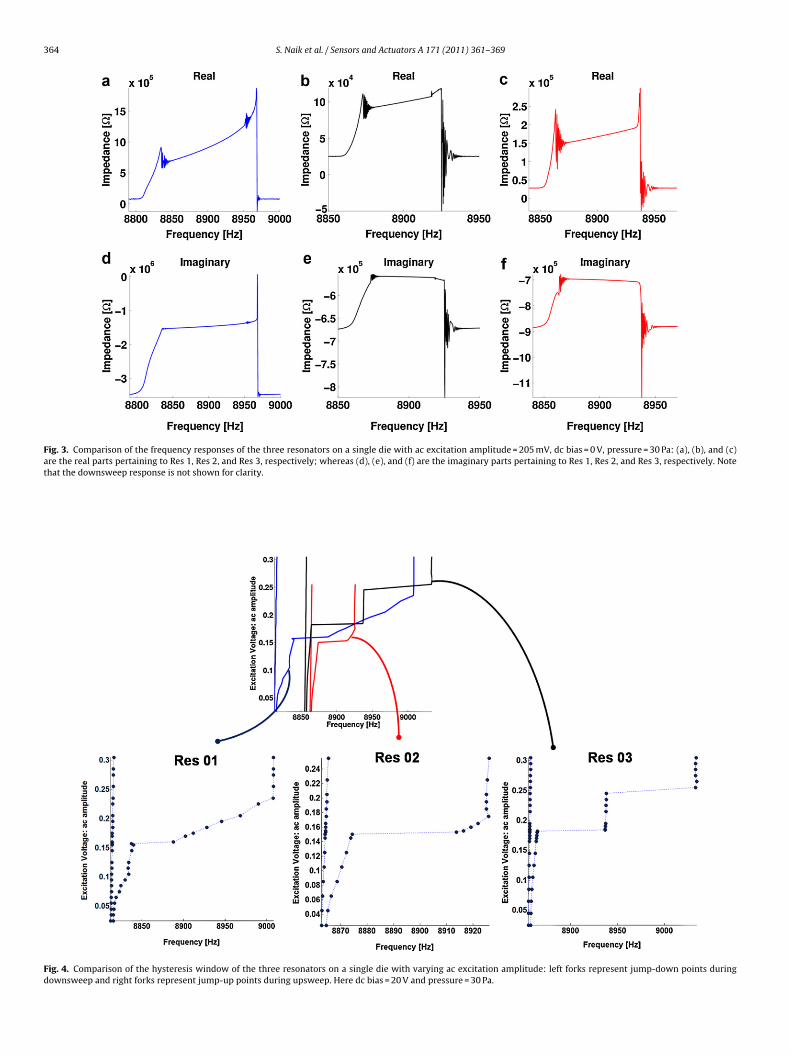
Fig. 4. Comparison of the hysteresis window of the three resonators on a single die with varying ac excitation amplitude: left forks represent jump-down points duringdownsweep and right forks represent jump-up points during upsweep. Here dc bias = 20 V and pressure = 30 Pa.

S. Naik et al. / Sensors and Actuators A 171 (2011) 361– 369 365
Fig. 5. Test setup and in-phase vibrations: (a) block diagram of the coupling circuit used in the experiments and (b) emergent in-phase vibrations without the ac excitationsignal.
Fig. 6. The coupled system with a priori in-phase vibrations in the presence of ac excitation signal: region of synchronization is shown where x-axis denotes the frequencyof the excitation signal and y-axis denotes the peak-to-peak voltage level of excitation signal. Outside of the sync region, the oscillations are quasiperiodic as shown in theinsets.

366 S. Naik et al. / Sensors and Actuators A 171 (2011) 361– 369
F rcuit uo sure =
thmr
s2wtAssatt
Fs
ig. 7. Test setup and out-of-phase vibrations: (a) block diagram of the coupling cif self-excited oscillations is 8.991 kHz with the test conditions bias = 20 V and pres
he possibility that the outer beams need to be engaged into aigher mode of vibration. This feature is crucial in facilitatingultiple bifurcations in the resonator and thereby extending the
esponse.Fig. 4 shows the comparison of the hysteresis window while
weeping the ac excitation voltage. Here it can be seen that Res shows the smallest window whereas Res 1 exhibits the largestindow almost covering the other two resonator windows. The
ransition to the extended hysteresis in all three resonators is clear.lso note that at high enough ac excitation voltages, the windowstay nearly constant. This is particularly evident in the upper right
ide of the right forks for the three resonators. These values ofc excitation voltage seem to be the limit after which the ampli-ude of the vibrations stays nearly constant. By this comparisonhe characterization of the individual resonators is comprehensiveig. 8. The coupled system with out-of-phase vibration at nearly identical amplitude levelf-excited oscillations = 8.864 kHz with the test conditions bias = 20 V and pressure = 100
sed in the experiments and (b) emergent out-of-phase oscillations. The frequency 30 Pa.
and now they can be utilized in the coupled system under varyingac excitation amplitude and frequency (see Section 5).
4.1.2. Change in bias voltageThe behavior exhibited by the resonators while sweeping the
bias values from low to high at constant ac excitation voltagewas qualitatively similar to the results shown in the previous sec-tion. However, the electrostatic force increases significantly whileincrementing the bias voltage. This is due to the increase in thesteady-state capacitance between the comb fingers. It was observedthat the resonators display a nonlinear resonance at low bias and
the extension of the hysteresis depends more on the bias voltagethan the ac excitation amplitude. For example, a high ac excitationamplitude at low bias voltage did not always induce the extendedhysteresis. As mentioned in the previous section the frequency atels: (a) self-excited oscillations and (b) region of synchronization. The frequency of Pa.

S. Naik et al. / Sensors and Actuators A 171 (2011) 361– 369 367
F ationsf
wt
4
tovrtbtbtttitttbrdisep
5
i
ig. 9. Synchronization of a priori quasiperiodic oscillations: (a) self-excited oscill = 8.949 kHz. Here f denotes the excitation frequency.
hich the extension occurs in a given resonator, while sweepinghe bias, was observed to be identical.
.1.3. Mechanism for the extended nonlinear resonanceThe causes of the nonlinear behavior shown in the above sec-
ions are as follows. As the structure resonates, the inner beams anduter beams shown in Fig. 1a expand and compress together (viceersa in the other direction). Normally this helps extend the linearange of the resonator. Also the compliance in the truss can par-ially relieve the axial compression. However, the long and narroweams can be axially loaded when they experience a large elec-rostatic force during the peak resonance [9]. As a result the innereams develop higher modes of vibration due to high tensile forceo maintain equilibrium. Additionally the outer beams are designedo be stiffer than the inner beams with a ratio of 1.27; hence theyend to compress less. This type of nonuniform stress distributionn the inner and outer beams can cause more hardening. Also notehe location of the four beams on the truss; the distance betweenhe inner and outer beam in a given pair and the distance betweenwo given pairs are not equal. Additionally the outer beams can alsoe axially loaded and can exhibit a higher mode of vibration as aesult of the nonuniform expansion and contraction. All these con-itions can cause the mass to sustain the vibrations as the frequency
s swept past the resonance frequency and as a result the exten-ion of hysteresis can occur. The mechanism behind hysteresis andxtended hysteresis has already been discussed in our previousaper [20].
. Coupled resonators
The coupled experiment was performed by using the resonatorsn Group II. The test die was attached by non-conductive epoxy
, (b) out- of-sync at f = 8.90 kHz, (c) in-sync at f = 8.906 kHz, and (d) out-of-sync at
in the center of the device PCB and devices were wire-bonded tothe pcb traces using gold wires with 1 mil (∼25 �m) diameter. Asmentioned in Section 3, one of the electrodes was grounded andthe excitation signal was connected to the other electrode. Themotional current produced by the device was read off the anchorpad. The substrate, the pcb, and the vacuum chamber were alsogrounded to reduce parasitic capacitances. The experiments wereconducted on a motion resistant test-bench to dampen the ambi-ent vibrations. The three resonators on a single die were coupledtogether by discrete electronics such that they form a closed-loopsystem, i.e. 1→ 2→ 3→1.
5.1. In phase vibrations
In this section, in-phase vibrations produced by the coupledsystem are discussed in detail in the following subsections.
5.1.1. Autonomous system (no ac excitation signal)In this experiment the devices were biased using a dc power
supply. As shown in Fig. 5a the output of a given resonator was fedto current-to-voltage (I-V) converter which was connected to anamplifier with variable gain. This variable gain amplifier allowedthe overall coupling strength between the resonators to be tun-able. The output of the coupling amplifier was then connectedto the next element in the ring. The initial positions of the res-onators were reset by applying the bias of 20 V simultaneously.Next the resonators were self-excited by adjusting the gains of thecoupling amplifiers. As the noise in the system traverses around
the loop and is amplified, the resonators start to vibrate. Eventu-ally at sufficiently high vibration the resonators synchronize witheach other and stable sinusoidal vibrations emerge depending onthe coupling strengths. Fig. 5b shows the full grown vibrations of
3 Actuat
R92ropewiAdtbqso
5
tTtawrctdosnc
5
iKaannvacacttRvsbAar08iwolrbrb
68 S. Naik et al. / Sensors and
es 3. Here the shared frequency of oscillation is approximately kHz and the amplitude levels are 2.12 V for Res 1, 0.68 V for Res, and 1.86 V for Res 3. While tuning the coupling strengths, a nar-ow range of frequencies was observed in which stable vibrationsccur. It was observed that for all possible combinations of the cou-ling strengths that produce stable vibrations, two of the resonatorsxhibit nearly identical amplitude levels while the third resonatorould stay at about half of their levels. This can be due to mismatch
n the resonators and/or the interface electronics used for coupling.lso note that the difference in the coupling strengths can also pro-uce asymmetric vibrations between the resonators which affecthe amplitude levels. In addition to that the in-phase vibrations cane attributed to strong coupling between the resonators. The fre-uency and the amplitude of the vibrations increase as the couplingtrengths are carefully matched and increased. Other combinationsf the coupling produce unstable (quasiperiodic) vibrations.
.1.2. Synchronization with the ac excitation signalIn this experiment, the ac excitation with dc bias was connected
o the input ports of the coupled system via a bias-tee network.he 1:1 region of synchronization is shown in Fig. 6, inside whichhe frequency of the coupled system was observed to be the sames the excitation frequency. Unstable (quasiperiodic) oscillationsere observed outside of the boundaries. It was observed that the
egion of synchronization can shrink, widen, or shift by changingoupling strengths which impact the self-excited frequencies andhe amplitude levels. The influence of large nonlinearity is also evi-ent by the curved boundaries. Below 100 mV, the vibrations werebserved to be unstable with substantial quasiperiodicity. It is pos-ible for this region to be closed depending on damping and theoise in the circuit. For example, at the pressure of 15 Pa the sameoupled system shows a wider area below 100 mV.
.2. Out of phase vibrations
For this experiment, the coupling circuit shown in Fig. 5 wasmproved by adding an RC low pass stage followed a 2-pole Sallen-ey low pass filter with a cutoff frequency around 15 kHz and with
sharp roll-off. As shown in Fig. 7a, the filter was followed by andder circuit with a gain stage in order to add the ac excitation sig-al to the given resonator signal. This was followed by the bias-teeetwork where the combined signals were added to the dc biasoltage. For the autonomous system only the dc bias voltage wasdded by using the bias-tee network. For all the experiments dis-ussed in this section the gain of the coupling amplifier was fixednd only the gain of the adder circuit was changed in order tohange the coupling strength. Out of phase oscillations emerge ashe couplings strengths are changed to a specific ratio. The ampli-ude levels are 0.256 V for Res 1, 0.152 V for Res 2, and 0.184 V fores 3 and the oscillation frequency is 8.991 kHz. The out-of-phaseibrations exhibit nearly 2�/3 phase difference with each other aseen in Fig. 7b. However, this state of the coupled system proved toe difficult to synchronize in the presence of the excitation signal.nother pattern of out-of-phase vibrations with nearly identicalmplitude levels was obtained by a slight change in the couplingatio as shown in Fig. 8a. The amplitude levels are 0.58 V for Res 1,.64 V for Res 2, and 0.58 V for Res 3 and the oscillation frequency is.664 kHz. Fig. 8b shows the associated region of synchronization
n the presence of the excitation signal. Note that the pressure levelas dropped to 100 Pa for these experiments; however, emergent
scillations similar to the ones at 30 Pa were observed. Here theeft boundary was easier to obtain whereas the oscillations showed
apid fluctuations around the right boundary. This behavior cane attributed to the mismatch between the resonators and theirelative engagement/disengagement of the extended hard-springehavior shown in Fig. 3.ors A 171 (2011) 361– 369
In an another experiment the out-of-phase a priori vibrationsshown in the previous section were changed to quasiperiodic(unstable) vibrations by changing the coupling strengths. It wasobserved that in the presence of excitation signal with substan-tial amplitude, this state of the coupled system also exhibits anentrainment to the excitation frequency as shown in Fig. 9. How-ever, a full region of synchronization was difficult to obtain for thistype of oscillations due to the excessive instability present in theautonomous system with this set of coupling strengths.
6. Conclusions
In this paper, the experimental results of nonlinear MEMS res-onators were reported. It was shown that the variation in theexcitation voltage affects the frequency response significantly. Anextension of the hysteresis and thus an enlargement of usableamplitude bandwidth were observed in all the resonators. Theresonators on single die showed better matching than the res-onators from the separate dies. The resonators on separate diesdid not show any promising coupled dynamics. Therefore the ben-efits of nonlinear resonance were demonstrated by electronicallycoupling the resonators on single die in a closed-loop. The unidirec-tionally coupled system exhibited stable self-excited oscillationsdepending on the coupling strengths and it also synchronized tothe excitation signal. Both the in-phase and the out-of-phase vibra-tions were observed. An analytical and numerical study includingthe bifurcation analysis and synchronization of the coupled sys-tem was carried out and shown in a recently submitted paper.This study showed that the coupled system can exhibit self-excitedoscillations with 2�/3 phase difference when the coupling strengthexceeds a critical value. In the presence of the excitation signal itcan exhibit 1:1 sync region and a very narrow 1:3 sync region. Thequalitative behavior of the 1:1 sync region in the simulations andthe experiments was observed to be similar. However, 1:3 syncregion was not observed in the experiments. The experimentalstudy shown in this paper indicates that the coupled system hasa strong potential as a sensor depending on the applications.
Acknowledgments
This work was supported in part by Global Center of Excellence(GCOE) program at Kyoto University, Kyoto Environmental Nano-technology Cluster, Regional Innovation Cluster Program 2010, andMinistry of Education, Culture, Sports, Science and Technology(MEXT). S.N. was partially supported by NSF grant CMMI-0923803to visit and conduct research with the group at San Diego StateUniv and SSC Pacific. S.N. and T.H. also wish to thank Mr. HiroyukiTokusaki, Dr. Toshiyuki Tsuchiya, and Dr. Osamu Tabata (Dept. ofMicro Engineering, Kyoto University) and Dr. Sam Kassegne (Dept.of Mechanical Engineering, San Diego State University) for theirsupport. H.V. and A.P. were supported in part by National ScienceFoundation grants CMS-0923803 and CMS-0625427. V.I. is sup-ported by the Office of Naval Research, Code 30.
References
[1] A. Partridge, J. McDonald, MEMS to replace quartz oscillators as frequencysources, NASA Technical Brief 30 (June Issue) (2006).
[2] L. Yan, M. Wu, W. Tang, A 1.14 GHz piezoelectrically transduced disk resonator,in: 18th IEEE Int. Conf. on MEMS, 30, 2005, pp. 203–206.
[3] V. Kaajakari, T. Mattila, A. Oja, H. Seppa, Nonlinear limits for single-crystalsilicon microresonators, Journal of MEMS 13 (2004) 715–724.
[4] R. Mestrom, R. Fey, J. van Beek, K.L. Phan, H. Nijmeijer, Modelling the dynamicsof a MEMS resoantor: simulations and experiments, Sensors and Actuators A
142 (2008) 306–315.[5] C. Nguyen, R. Howe, An integrated CMOS micromechanical resonator high-qoscillator, IEEE Journal of Solid-state Circuits 34 (1999) 440–455.
[6] S. Beeby, MEMS Mechanical Sensors, 2nd ed., Artech House Publishers, Nor-wood, 2004.
Actuat
[
[
[
[
[
[
[
[
[
[
[20] S. Naik, T. Hikihara, Characterization of a MEMS resonator with extended hys-
S. Naik et al. / Sensors and
[7] Y.C. Wang, S.G. Adams, J.S. Thorp, Chaos in MEMS, parameter estimation and itspotential application, IEEE Transactions on Circuits and Systems I: FundamentalTheory and Applications 45 (1998) 1013–1020.
[8] F. Hoppensteadt, E. Izhikevich, Synchronization of MEMS resonators andmechanical neurocomputing, IEEE Transactions on Circuits and Systems 48(2001) 133–138.
[9] C. Acar, A. Shkel, MEMS Vibratory Gyroscopes, Springer Science + BusinessMedia, 2009.
10] K. Wang, C. Nguyen, High-order micromechanical electronic filters, IEEE Inter-national Micro Electro Mechanical Systems Workshop (1997) 25–30.
11] V. Chivukula, J. Rhoads, Microelectromechanical bandpass filters based oncyclic coupling architectures, Journal of Sound and Vibration 329 (2010)4313–4332.
12] S. Shim, M. Imboden, P. Mohanty, Synchronized oscillation in coupled nanome-chanical oscillators, Science 316 (2007) 95–99.
13] E. Buks, M. Roukes, Electrically tunable collective response in a coupled
micromechanical array, Journal of Microelectromechanical Systems 11 (2002)802–807.14] E. Sanchez, M. Matias, Experimental observation of a periodic rotating wave inrings of unidirectionally coupled analog Lorenz oscillators, Physical Review E57 (1998) 6184–6186.
[
[
ors A 171 (2011) 361– 369 369
15] P. Perlikowski, S. Yanchuk, M. Wolfrum, A. Stefanski, P. Mosilek, T. Kapitaniak,Routes to complex dynamics in a ring of unidirectionally coupled systems,Chaos 20 (2010), 013111.1–013111.10.
16] V. In, A.R. Bulsara, A. Palacios, P. Longhini, A. Kho, J.D. Neff, Coupling-inducedoscillations in overdamped bistable systems, Physical Review E 68 (2003),045102.1–045102.4.
17] V. In, P. Longhini, N. Liu, A. Kho, J.D. Neff, A. Palacios, A.R. Bulsara, A bistablemicroelectronic circuit for sensing extremely low electric field, Journal ofApplied Physics 107 (2010), 014506.1–014506.8.
18] A. Palacios, R. Carretero-Gonzlez, P. Longhini, N. Renz, Multifrequency synthesisusing two coupled nonlinear oscillator arrays, Physical Review E 72 (2005),026211.1–026211.9.
19] H. Vu, A. Palacios, V. In, P. Longhini, J.D. Neff, Two-time scale analysisof a ring of coupled vibratory gyroscopes, Physical Review E 81 (2010),031108.1–031108.14.
teresis, IEICE Electronics Express 8 (2011) 291–298.21] A. Cowen, G. Hames, D. Monk, S. Wilcenski, B. Hardy, Soimumps Design Hand-
book Revision 6.0, MEMSCAP, Inc., 2009.22] R. Seydel, Practical Bifurcation and Stability Analysis, Springer-Verlag, 1994.