A micromechanical analysis of a local failure criterion for particle-reinforced composites
14
Accepted Manuscript peer-00498981, version 1 - 9 Jul 2010 Author manuscript, published in "Composites Science and Technology 67, 11-12 (2007) 2384" DOI : 10.1016/j.compscitech.2007.01.002
-
Upload
mines-douai -
Category
Documents
-
view
1 -
download
0
Transcript of A micromechanical analysis of a local failure criterion for particle-reinforced composites
Accepted Manuscript
A micromechanical analysis of a local failure criterion for particle-reinforced
composites
Johann Guilleminot, Djimedo Kondo, Christophe Binetruy, Stephane Panier,
Said Hariri, Patricia Krawczak
PII: S0266-3538(07)00038-3
DOI: 10.1016/j.compscitech.2007.01.002
Reference: CSTE 3571
To appear in: Composites Science and Technology
Received Date: 6 June 2006
Accepted Date: 12 January 2007
Please cite this article as: J. Guilleminot, D. Kondo, C. Binetruy, S. Panier, S. Hariri, P. Krawczak, A
micromechanical analysis of a local failure criterion for particle-reinforced composites, Composites Science and
Technology (2007), doi: 10.1016/j.compscitech.2007.01.002
This is a PDF file of an unedited manuscript that has been accepted for publication. As a service to our customers
we are providing this early version of the manuscript. The manuscript will undergo copyediting, typesetting, and
review of the resulting proof before it is published in its final form. Please note that during the production process
errors may be discovered which could affect the content, and all legal disclaimers that apply to the journal pertain.
peer
-004
9898
1, v
ersi
on 1
- 9
Jul 2
010
Author manuscript, published in "Composites Science and Technology 67, 11-12 (2007) 2384" DOI : 10.1016/j.compscitech.2007.01.002

ACCEPTED MANUSCRIPT
A micromechanical analysis of a local failure
criterion for particle-reinforced composites
Johann Guilleminot a, Djimedo Kondo b, Christophe Binetruy a,Stephane Panier a, Said Hariri a, Patricia Krawczak a
aEcole des Mines de Douai, Polymers and Composites Technology & MechanicalEngineering Department, 941 rue Charles Bourseul, BP 10838, 59508 Douai
Cedex, FrancebLaboratoire de Mecanique de Lille-UMR CNRS 8107, Universite de Sciences et
Technologies Lille,Cite Scientifique, Bd. Paul Langevin, 59655 Villeneuve d’Ascq Cedex, France
Abstract
The present paper aims at predicting the ultimate mechanical properties of a particle-reinforced polymer using a micromechanical approach of a local failure criterion.The considered criterion includes both normal and shear stresses at the interfacebetween the polymer matrix and the reinforcing material. In the case of rigid par-ticles, a new closed-form expression of the interfacial stress concentration tensor isprovided and simple analytical formula are proposed and compared for different ho-mogenization schemes. A combination of these results with acoustic emission dataallows the identification of the parameters involved in the local failure criterion. Ithas been shown that the predicted interfacial strength highly depends on the choiceof a suitable homogenization scheme.
Key words: Particle-reinforced composites, Interfacial strength, Mechanicalproperties, Acoustic emission, Stress concentrations
1 Introduction
Polymer composites have been used for many years in several applications suchas aircraft, space and marine structures, mass transport systems, automotive
Email addresses: [email protected] (Johann Guilleminot),[email protected] (Djimedo Kondo).
Preprint submitted to Elsevier Science 6th June 2006
peer
-004
9898
1, v
ersi
on 1
- 9
Jul 2
010

ACCEPTED MANUSCRIPT industries, building and construction. The experience gained in all these ap-
plications showed that the in-service behavior of a polymer composite highlydepends on the properties of the reinforcing particle-matrix or endless fibre-matrix interface that contributes to stress transfer. The reinforcing particlecan be a filler or a chopped fiber. This explains why the study of interfacesreceived much attention in order to understand phenomena and mechanismsinvolved there. Adhesion is one the most fundamental aspect addressed in thisarea because interfacial debonding is, with particle breakage, one of the basiclocal failure modes in particle-reinforced composites. The study of such localfailure mechanism classically requires the use of a stress-based local approach.A suitable analysis can be performed by using micromechanical approacheswhich allow to relate the microscopic (local) stress field to the macroscopicstress tensor.The determination of the local stress field, particularly at theparticle-matrix interface, depends on both the material microstructure andthe choice of a suitable homogenization scheme. In this paper, we investigatethe local criterion considered by Fitoussi et al. [2] and derive a new explicit for-mulation in the case of rigid particles, different homogenization schemes beingconsidered and compared for this purpose. Moreover, the closed-form resultsare combined with acoustic emission data in order to evaluate the mechanicalparameters involved in the criterion.
2 Local debonding criterion and micromechanical analysis
2.1 Local failure criterion
Let us consider a local failure criterion based on the stress field at the in-terface between the matrix and the reinforcing material. As previously usedby Fitoussi et al. [2], an example of this type of criterion consists in a linearcombination of the local normal and shear stresses and is defined as follows:
σoutn + βτ out
n = Rint (1)
where σoutn and τ out
n are the interfacial normal and shear stresses respectively; βand Rint are two parameters to be identified by an iterative regression betweenboth experimental and simulated results (see [2]). The local normal and shearstresses are classically defined as:σout
n = nT · σout · n
τ outn =
√‖σout · n‖2 − (nT · σout · n)2
(2)
where σout is the interfacial stress field and n is the outward unit normal tothe boundary on the interface point under consideration.
2
peer
-004
9898
1, v
ersi
on 1
- 9
Jul 2
010
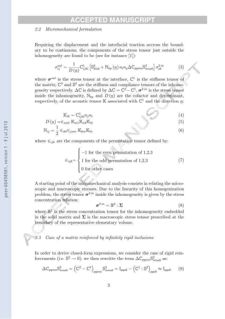
ACCEPTED MANUSCRIPT 2.2 Micromechanical formulation
Requiring the displacement and the interfacial traction accross the bound-ary to be continuous, the components of the stress tensor just outside theinhomogeneity are found to be (see for instance [1]):
σoutij =
1
D (n)C1
ijkl
[S2
klab + Nkp (n) nlnq∆CpqmnS2mnab
]σ2 in
ab (3)
where σout is the stress tensor at the interface, C1 is the stiffness tensor ofthe matrix; C2 and S2 are the stiffness and compliance tensors of the inhomo-geneity respectively. ∆C is defined by ∆C = C2−C1, σ2 in is the stress tensorinside the inhomogeneity, Nkp and D (n) are the cofactor and determinant,respectively, of the acoustic tensor K associated with C1 and the direction n:
Kik = C1ijklnjnl (4)
D (n) =∈mnl Km1Kn2Kl3 (5)
Nij =1
2∈ikl∈jmn KkmKln (6)
where ∈ijk are the components of the permutation tensor defined by:
∈ijk=
−1 for the even permutation of 1,2,3
1 for the odd permutation of 1,2,3
0 for other cases
(7)
A starting point of the micromechanical analysis consists in relating the micro-scopic and macroscopic stresses. Due to the linearity of this homogenizationproblem, the stress tensor σ2 in inside the inhomogeneity is given by the stressconcentration relation:
σ2 in = B2 : Σ (8)
where B2 is the stress concentration tensor for the inhomogeneity embeddedin the solid matrix and Σ is the macroscopic stress tensor prescribed at theboundary of the representative elementary volume.
2.3 Case of a matrix reinforced by infinitely rigid inclusions
In order to derive closed-form expressions, we consider the case of rigid rein-forcements (i.e. S2 → 0); we then rewritte the term ∆CpqmnS2
mnab as:
∆CpqmnS2mnab =
(C2 − C1
)pqmn
S2mnab = Ipqab −
(C1 : S2
)pqab
≈ Ipqab (9)
3
peer
-004
9898
1, v
ersi
on 1
- 9
Jul 2
010
ACCEPTED MANUSCRIPT where I is the symmetric fourth-order identity tensor defined by Ipqab =
12(δpaδqb + δpbδqa), δ is the Kronecker delta (δij = 1 for i = j and δij = 0
for i 6= j). Taking into account (9), we have:
Nkp (n) nlnq∆CpqmnS2mnab = Nkp (n) nlnqIpqab (10)
which also reads
Nkp (n) nlnq∆CpqmnS2mnab =
1
2{Nka (n) nlnb + Nkb (n) nlna} = N (n)⊗ (n⊗ n)
(11)where (A⊗B)klab = 1
2[AkaBlb + AkbBla] for any second order tensors A and
B.
Then, equation (3) can be rewritten in a more readily and compact tensorialform:
σout =1
D (n)C1 : [N (n)⊗ (n⊗ n)] : σ2 in (12)
Let us recall now that for different homogenization schemes, the stress con-centration tensor which enters (8) is classically given for the inhomogeneityby (see for instance [8]):
B2 = B2i :
(2∑
k=1
f rBri
)−1
(13)
where f r is the volume fraction of the phase r (the superscripts 0, 1 and 2 de-note some reference medium, the matrix and the inhomogeneity respectively)and Br
i is defined by:
Bri =
[I + Q0 :
(Sr − S0
)]−1(14)
where Sr is the compliance tensor of the phase r and Q0 is defined by :
Q0 = C0 − C0 : P20 : C0 (15)
P20 is the Hill tensor (see [11]). Since C0 : S0 = I and S2 → 0, one easily gets:
B1i = [I + Q0 : (S1 − S0)]
−1
B2i ≈ (C0 : P2
0)−1
(16)
Substituting (16) into (13) and recalling that (A : B)−1 = B−1 : A−1 (A andB being any symmetric fourth-order tensor, i.e. Aijkl = Ajikl = Aijlk = Aklij)
4
peer
-004
9898
1, v
ersi
on 1
- 9
Jul 2
010

ACCEPTED MANUSCRIPT and f 1 = 1− f 2, we obtain for the two phase composites:
B2 = B2i : [(1− f 2) B1
i + f 2B2i ]−1 ≈
[(1− f 2) [I + Q0 : (S1 − S0)]
−1: C0 : P2
0+
f 2I]−1
(17)and then, we finally define a new tensor,
Bout = 1D(n)
C1 : [N (n)⊗ (n⊗ n)] :[(1− f 2) [I + Q0 : (S1 − S0)]
−1: C0 : P2
0+
f 2I]−1
(18)such as:
σout = Bout : Σ (19)
Bout can be considered, for rigid inhomogeneities, as a concentration tensor forthe interfacial stress field: it is readily seen that this new tensor Bout depends onboth the geometry of the inhomogeneity (via the tensor P2
0) and the propertiesof the reference medium denoted by the superscript 0. Therefore, note that theexpression of Bout clearly depends on the homogenization scheme (see section2.4).
2.4 Role of the homogenization schemes
Different homogenization schemes are going to be considered in the following.For the dilute estimate (also known as the Eshelby’s solution, see for instance[4]), classically devoted to non interacting inhomogeneities (at dilute concen-tration), the matrix is considered as the reference medium (i.e. S0 = S1) andis subjected to the macroscopic stress tensor. The validity of this approachcorresponds to f 2 → 0 and thus to, B2 → (C1 : P2
0)−1
. We recall that in gen-eral, P2
0 = SESH : (C0)−1
, where SESH is the Eshelby tensor which depends onboth the geometry of the inhomogeneity and the reference medium (see [1]).Therefore, eqn (18) yields:
BoutESH =
1
D (n)C1 : [N (n)⊗ (n⊗ n)] :
(C1 : P2
1
)−1(20)
where obviously, P21 = (P2
0)Dilute estimate = SESH : (C1)−1
.
For the Mori-Tanaka estimate [10] (see also [5]), which allows to take intoaccount the interactions between the inhomogeneities, the solid matrix is stillconsidered as the reference medium, but is now subjected to its own stress. It
5
peer
-004
9898
1, v
ersi
on 1
- 9
Jul 2
010
ACCEPTED MANUSCRIPT follows that:
BoutMT =
1
D (n)C1 : [N (n)⊗ (n⊗ n)] :
[(1− f 2
)C1 : P2
1 + f 2I]−1
(21)
In the Generalized Self-Consistent scheme [6], the reference medium is theunknown effective medium denoted by SC, that is S0 = SSC . Then, eqn (18)becomes:
BoutSC = 1
D(n)C1 : [N (n)⊗ (n⊗ n)] : [(1− f 2) [I+
QSC :(S1 − SSC
)]−1: CSC : P2
SC + f 2I]−1 (22)
Finally, the Ponte-Castaneda and Willis estimate [7] aims at taking into ac-count not only the interaction effect, but also the spatial distribution of thereinforcing material by means of a new tensor Pd (see [7] for a detailed pre-sentation as well as the expression of Pd). In this approach, the tensor P2
1 isthen replaced by 1
1−f2 [P21 − f 2Pd] and we get:
BoutPCW =
1
D (n)C1 : [N (n)⊗ (n⊗ n)] :
(C1 :
[P2
1 − f 2Pd
]+ f 2I
)−1(23)
3 Case of a polymer-matrix composite reinforced by spherical in-homogeneities: a comparison between micromechanical schemes
3.1 Introduction
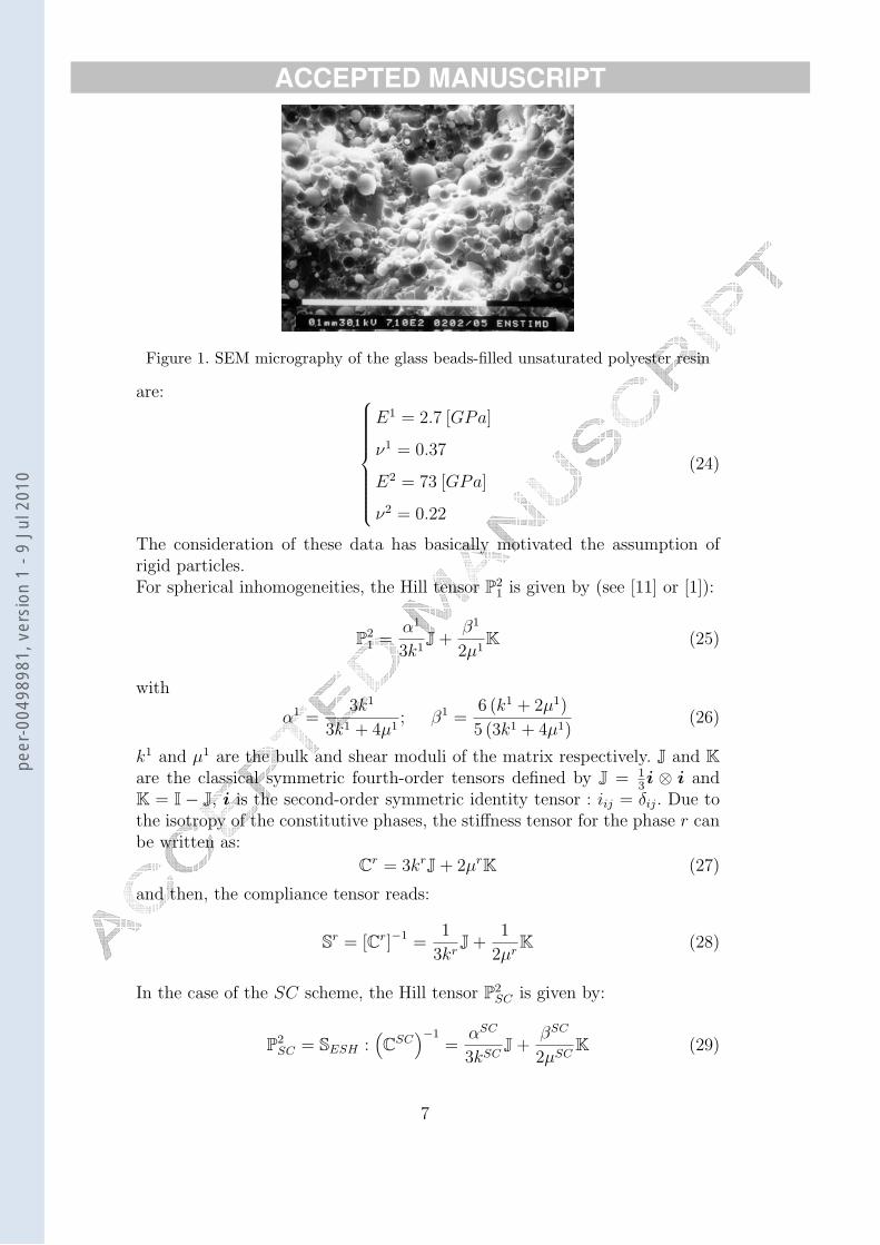
In this section, we consider an isotropic unsaturated polyester matrix rein-forced by E-Glass spherical beads (volume fraction : 30 %). Our aim here isto determine the sensitivities of both the parameter Rint and the local stressfield to the homogenization scheme. The spherical particles have been burntfive hours at 520◦ C to remove sizing in order to promote interfacial debondinginstead of matrix cracking. Fig. (1) shows a SEM inspection of the compositematerial. The lack of polymer matrix at the particle surface, i.e. the particlesurface is smooth, gives the evidence that interfacial debonding is the damagemechanism.The values of the elastic moduli and Poisson’s ratios for each phase (the super-scripts 1 and 2 correspond to the matrix and the inhomogeneity respectively)
6
peer
-004
9898
1, v
ersi
on 1
- 9
Jul 2
010
ACCEPTED MANUSCRIPT
Figure 1. SEM micrography of the glass beads-filled unsaturated polyester resin
are:
E1 = 2.7 [GPa]
ν1 = 0.37
E2 = 73 [GPa]
ν2 = 0.22
(24)
The consideration of these data has basically motivated the assumption ofrigid particles.For spherical inhomogeneities, the Hill tensor P2
1 is given by (see [11] or [1]):
P21 =
α1
3k1J +
β1
2µ1K (25)
with
α1 =3k1
3k1 + 4µ1; β1 =
6 (k1 + 2µ1)
5 (3k1 + 4µ1)(26)
k1 and µ1 are the bulk and shear moduli of the matrix respectively. J and Kare the classical symmetric fourth-order tensors defined by J = 1
3i ⊗ i and
K = I − J, i is the second-order symmetric identity tensor : iij = δij. Due tothe isotropy of the constitutive phases, the stiffness tensor for the phase r canbe written as:
Cr = 3krJ + 2µrK (27)
and then, the compliance tensor reads:
Sr = [Cr]−1 =1
3krJ +
1
2µrK (28)
In the case of the SC scheme, the Hill tensor P2SC is given by:
P2SC = SESH :
(CSC
)−1=
αSC
3kSCJ +
βSC
2µSCK (29)
7
peer
-004
9898
1, v
ersi
on 1
- 9
Jul 2
010

ACCEPTED MANUSCRIPT for which we recall that kSC and µSC are the effective bulk and shear moduli
of the composite respectively. αSC and βSC are obtained from (26) in which k1
and µ1 must be replaced by kSC and µSC respectively. Moreover, experimentalresults in the case of a tensile test suggest that the debonding does appear atthe pole of the spherical particle, as illustrated on Fig. (2).Then, we note that:
Reinforcing spherical
inhomogeneities
Initiation of the interfacial debonding
Matrix
Figure 2. Interfacial debonding during a tensile test
σoutn, pole = Max
(σout
n
), τ out
n, pole = 0 (30)
and recalling eqn (1), we get:
Rint = σoutn, pole (31)
It follows that Rint can be determined by a pure macroscopic uniaxial tensiletest coupled with an acoustic emission measure, as the debonding macroscopicforce Fdeb (and so, the interfacial failure) can be determined by comparing theacoustic emission (AE) results (that are the counts and the amplitude - indB - vs. time - in seconds -) with the tensile test results (the force - in N- vs. time); see section (3.3). We recall here that AE is widely used for nondestructive control as well as to identify and to monitor damage mechanismsand evolution (see for instance [9] or [3]). In fact, each failure mode can becharacterized by a range of amplitude; the debonding phenomena basicallycorresponds to the range [58...68] dB. Thus, we define the macroscopic tensilestress tensor Σ (which is used for the micromechanical analysis) by :
Σ = Diag [0, 0, Σ33] (32)
8
peer
-004
9898
1, v
ersi
on 1
- 9
Jul 2
010
ACCEPTED MANUSCRIPT 3.2 Sensitivity of the local stress field
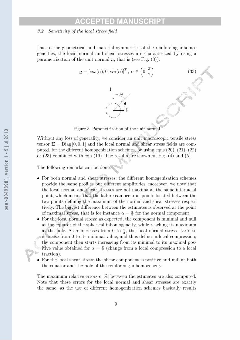
Due to the geometrical and material symmetries of the reinforcing inhomo-geneities, the local normal and shear stresses are characterized by using aparametrization of the unit normal n, that is (see Fig. (3)):
n = [cos(α), 0, sin(α)]T , α ∈(0,
π
2
)(33)
Figure 3. Parametrization of the unit normal
Without any loss of generality, we consider an unit macroscopic tensile stresstensor Σ = Diag [0, 0, 1] and the local normal and shear stress fields are com-puted, for the different homogenization schemes, by using eqns (20), (21), (22)or (23) combined with eqn (19). The results are shown on Fig. (4) and (5).
The following remarks can be done:
• For both normal and shear stresses: the different homogenization schemesprovide the same profiles but different amplitudes; moreover, we note thatthe local normal and shear stresses are not maxima at the same interfacialpoint, which means that the failure can occur at points located between thetwo points defining the maximum of the normal and shear stresses respec-tively. The biggest difference between the estimates is observed at the pointof maximal stress, that is for instance α = π
2for the normal component.
• For the local normal stress: as expected, the component is minimal and nullat the equator of the spherical inhomogeneity, while reaching its maximumat the pole. As α increases from 0 to π
2, the local normal stress starts to
decrease from 0 to its minimal value, and thus defines a local compression;the component then starts increasing from its minimal to its maximal pos-itive value obtained for α = π
2(change from a local compression to a local
traction).• For the local shear stress: the shear component is positive and null at both
the equator and the pole of the reinforcing inhomogeneity.
The maximum relative errors ε [%] between the estimates are also computed.Note that these errors for the local normal and shear stresses are exactlythe same, as the use of different homogenization schemes basically results
9
peer
-004
9898
1, v
ersi
on 1
- 9
Jul 2
010

ACCEPTED MANUSCRIPT
( )MPa outnσ DILUTE
SC
PCW wd=0.8 MTPCW wd=1.2
( )Radα
Figure 4. Distribution of the local normal stress
in different predictions for the interfacial stress field which is used for thedetermination of both local normal and shear stresses. The results are reportedin table (1).
Dilute Mori-Tanaka SC PCW wd = 0.8 PCW wd = 1.2
Dilute 0 [%] 22.6 [%] 6.9 [%] 20.1 [%] 24.6 [%]
Mori-Tanaka 0 [%] 16.8 [%] 3.1 [%] 2.6 [%]
SC 0 [%] 14.2 [%] 19 [%]
PCW wd := 0.8 0 [%] 5.6 [%]
PCW wd := 1.2 0 [%]Table 1Maximum relative errors for the different homogenization schemes
3.3 Sensitivity of the parameter Rint
For application purposes, the tensile test has been carried out on a Instrontensile machine and coupled with an acoustic emission system (threshold: 30dB). Eight tensile tests were carried out (see Fig. (6)) and a mean value for
10
peer
-004
9898
1, v
ersi
on 1
- 9
Jul 2
010

ACCEPTED MANUSCRIPT
( )MPa outnτ
DILUTE
SCPCW wd=0.8MTPCW wd=1.2
( )Radα
Figure 5. Distribution of the local shear stress
Fdeb was obtained:
Fdeb ≈ 39.42 [daN ] (34)
Given a mean section of S = 37.84 [mm2], we find the uniaxial debondingmacroscopic stress as:
Σdeb =Fdeb
S≈ 10.42 [MPa] (35)
Substituting Σ33 = Σdeb in eqns (20), (21), (22) and (23) and using eqn (19),we finally derive the estimates of Rint for the different homogenization schemesunder consideration (see table (2)).
Homogenization Scheme Estimate of Rint
Dilute 20.06 [MPa]
Mori-Tanaka 15.53 [MPa]
SC 18.67 [MPa]
PCW wd = 0.8 16.03 [MPa]
PCW wd = 1.2 15.13 [MPa]Table 2Estimates of Rint
11
peer
-004
9898
1, v
ersi
on 1
- 9
Jul 2
010

ACCEPTED MANUSCRIPT
CountsAmplitude (dB)
120 2500
Amplitude
Counts
100 2000
Interfacial debonding
80
1500
60
1000
40
50020
0 00 100 200 300 400 500 600 700
Time (s)
Figure 6. AE spectra (amplitudes and counts vs. time) used for the identificationof the debonding macroscopic force
It is seen that the predictions for the mechanical parameter Rint are verydifferent depending on the micromechanical formulation under consideration:a maximum relative error of 24.6[%] is for instance observed between thePonte-Castaneda and Willis (wd = 1.2) estimate and the Eshelby’s solutionwhich seems to overestimate the interfacial strength.
4 Concluding remarks
The role of the homogenization scheme in the analysis of a local failure cri-terion has been investigated. In particular, a new closed-form expression ofthe interfacial stress concentration tensor has been proposed in the case ofrigid particle-reinforced composites. The proposed methodology can be easilyapplied to a more general class of materials (for instance thermoplastics re-inforced with short or long fibres). The coupling of such a micromechanicalanalysis with acoustic emission data allowed us to determine the interfacialstrength whose sensitivity to the homogenization scheme is emphasized. Thus,it is observed that the predicted value of the interfacial strength (and in gen-
12
peer
-004
9898
1, v
ersi
on 1
- 9
Jul 2
010
ACCEPTED MANUSCRIPT eral, of the effective mechanical properties) strongly depends on the homoge-
nization scheme which in practice has to be carefully chosen according to thereal morphology of the material.
References
[1] Mura, T., ”Micromechanics of defects in solids”, M. Nijhoff Publ., The Hague,The Netherlands, 1987.
[2] Fitoussi, J., Guo, G., Baptiste, D., ”Determination of a tridimensional failurecriterion at the fibre/matrix interface of an organic-matrix/discontinuous-reinforcement composite”, Composites Science and Technology, Vol. 56, p.755-760, 1995.
[3] Barre, S., Benzeggah, M. L., ”On the use of acoustic emission to investigatedamage mechanisms in glass-fibre-reinforced polypropylene”, CompositesScience and Technology, Vol. 54, p.369-376, 1994.
[4] Eshelby, J. D., ”The determination of the elastic field of an ellipsoidal inclusion,and related problems”, Proceedings of the Royal Society, Series A, Vol. 241,p.376-396, 1957.
[5] Benveniste, Y., ”A new approach to the application of Mori-Tanaka’s theory incomposite materials”, Mechanics of Materials, Vol. 6, p.147-157, 1987.
[6] Christensen, R. M., ”A critical evaluation for a class of micromechanics models”,J. Mech. Phys. Solids, Vol. 38, p.379-404, 1988.
[7] Ponte-Castaneda, P., Willis, J. R., ”The effect of spatial distribution on theeffective behavior of composite materials and cracked media”, J. Mech. Phys.Solids, Vol. 43, p.1919-1951, 1995.
[8] Bornert, M., Bretheau, T., Gilormini, P., ”Homogenization in Mechanics ofMaterials”, Iste Publishing Company, 2006.
[9] Lariviere, D., Krawczak, P., Tiberi, C., Lucas, P., ”Acoustic emission appliedto failure analysis of commingled yarn GF/PP composites in transverse tensionand mode I delamination”, Advanced Composites Letters, Vol. 12, No. 5, p.191-202, 2003.
[10] Mori, T. and Tanaka, K. ”Average stress in matrix and average elastic energyof materials with misfitting inclusions”, Acta Metall. 21, 571-574, 1973.
[11] Nemat-Nasser, S., Hori, S., ”Micromechanics: overall propertiesof heterogeneous materials”, North-Holland series in applied mathematics andmechanics, The Netherlands, 1993.
13
peer
-004
9898
1, v
ersi
on 1
- 9
Jul 2
010