A micromechanical approach to elastic and viscoelastic properties of fiber reinforced concrete
13
A micromechanical approach to elastic and viscoelastic properties of fiber reinforced concrete V.F. Pasa Dutra, S. Maghous ⁎, A. Campos Filho, A.R. Pacheco a Department of Civil Engineering, Federal University of Rio Grande do Sul, Porto Alegre, RS, Brazil abstract article info Article history: Received 9 June 2009 Accepted 21 October 2009 Keywords: Short-fiber composite Creep (C) Micromechanics (C) Some aspects of the constitutive behavior of fiber reinforced concrete (FRC) are investigated within a micromechanical framework. Special emphasis is put on the prediction of creep of such materials. The linear elastic behavior is first examined by implementation of a Mori–Tanaka homogenization scheme. The micromechanical predictions for the overall stiffness prove to be very close to finite element solutions obtained from the numerical analysis of a representative elementary volume of FRC modeled as a randomly heterogeneous medium. The validation of the micromechanical concepts based on comparison with a set of experiments, shows remarkable predictive capabilities of the micromechanical representation. The second part of the paper is devoted to non-ageing viscoelasticity of FRC. Adopting a Zener model for the behavior of the concrete matrix and making use of the correspondence principle, the homogenized relaxation moduli are derived analytically. The validity of the model is established by mean of comparison with available experiment measurements of creep strain of steel fiber reinforced concrete under compressive load. Finally, the model predictions are compared to those derived from analytical models formulated within a one-dimensional setting. © 2009 Elsevier Ltd. All rights reserved. 1. Introduction Assessment of the macroscopic properties of composite materials is one of the major concerns in material and structural engineering. As far as the elastic properties of composites are concerned, the micro- mechanical techniques are nowadays widely applied and have proves successful. This is particularly the case for composites with periodic microstructure. Nevertheless, the application of micromechanical tools to the modeling of non-linear behavior of composites, and more specifically for composites with randomly distributed phases, is relatively recent and several issues are still open [1]. In particular, the determination of viscoelastic or strength properties of randomly heterogeneous material remains an important task. In this context, fiber reinforced concrete (FRC) represents a typical example of disordered material. FRC is a cement-based composite with improved mechanical properties in terms of tensile strength or fracture toughness. Such a material results from the association of a cement matrix and embedded fibers. Fibers used in the reinforcement of the concrete generally fall within one of the following four categories [2]: natural (sisal, coconut, bamboo, and jute), synthetic (acrylic, aramid, carbon, nylon, polyester, polyethylene, and polypropylene), glass and steel fiber. The main role of fiber addition is to minimize the emergence and propagation of cracks [3]. In addition, steel fibers are increasingly used as full or partial replacement of conventional web reinforcement in some structural concrete applications [4–6], since their inclusion in concrete mix has been shown to enhance shear resistance and ductility. Owing to the well-established performance of FRC, major efforts have been dedicated during the last decade to the modeling of its behavior. A traditional way to formulate the behavior of FRC is the phenomenological approach which consists in identifying the constitutive laws by means of laboratory tests [7–9]. The advantage of this approach lies on the direct access to material information at the relevant scale for the analysis of the structure. On the other hand, the main limitation of such phenomenological reasoning is connected with the extensive and costly experimental programs, which a complete characterization of the constitutive behavior would require. An attractive alternative to handling this kind of problem is provided by the framework of micromechanics. The scale adopted for the description of the composite components (i.e., phase properties and morphological information) is referred to as the microscopic scale, while the macroscopic scale is the engineer scale, i.e., that is considered for the analysis of the structure response under prescribed loading. Taking advantage of the condition of scale separation [1], FRC can therefore be regarded from a macroscopic viewpoint as a homogenized medium. Implementing the homogenization techniques (see for instance, [10–15]), the properties of the latter are evaluated from those of its constituents as well as from the knowledge of the shape and volume fraction of fibers. Cement and Concrete Research 40 (2010) 460–472 ⁎ Corresponding author. Tel.: +55 51 33 08 35 88; fax: +55 51 33 08 39 99. E-mail address: [email protected] (S. Maghous). 0008-8846/$ – see front matter © 2009 Elsevier Ltd. All rights reserved. doi:10.1016/j.cemconres.2009.10.018 Contents lists available at ScienceDirect Cement and Concrete Research journal homepage: http://ees.elsevier.com/CEMCON/default.asp
Transcript of A micromechanical approach to elastic and viscoelastic properties of fiber reinforced concrete
Cement and Concrete Research 40 (2010) 460–472
Contents lists available at ScienceDirect
Cement and Concrete Research
j ourna l homepage: ht tp: / /ees.e lsev ie r.com/CEMCON/defau l t .asp
A micromechanical approach to elastic and viscoelastic properties of fiberreinforced concrete
V.F. Pasa Dutra, S. Maghous ⁎, A. Campos Filho, A.R. Pachecoa Department of Civil Engineering, Federal University of Rio Grande do Sul, Porto Alegre, RS, Brazil
⁎ Corresponding author. Tel.: +55 51 33 08 35 88; faE-mail address: [email protected] (S. Maghou
0008-8846/$ – see front matter © 2009 Elsevier Ltd. Aldoi:10.1016/j.cemconres.2009.10.018
a b s t r a c t
a r t i c l e i n f oArticle history:Received 9 June 2009Accepted 21 October 2009
Keywords:Short-fiber compositeCreep (C)Micromechanics (C)
Some aspects of the constitutive behavior of fiber reinforced concrete (FRC) are investigated within amicromechanical framework. Special emphasis is put on the prediction of creep of such materials. The linearelastic behavior is first examined by implementation of a Mori–Tanaka homogenization scheme. Themicromechanical predictions for the overall stiffness prove to be very close to finite element solutionsobtained from the numerical analysis of a representative elementary volume of FRC modeled as a randomlyheterogeneous medium.The validation of the micromechanical concepts based on comparison with a set of experiments, showsremarkable predictive capabilities of the micromechanical representation.The second part of the paper is devoted to non-ageing viscoelasticity of FRC. Adopting a Zener model for thebehavior of the concrete matrix and making use of the correspondence principle, the homogenizedrelaxation moduli are derived analytically. The validity of the model is established by mean of comparisonwith available experiment measurements of creep strain of steel fiber reinforced concrete under compressiveload. Finally, the model predictions are compared to those derived from analytical models formulated withina one-dimensional setting.
x: +55 51 33 08 39 99.s).
l rights reserved.
© 2009 Elsevier Ltd. All rights reserved.
1. Introduction
Assessment of themacroscopic properties of compositematerials isone of themajor concerns inmaterial and structural engineering. As faras the elastic properties of composites are concerned, the micro-mechanical techniques are nowadays widely applied and have provessuccessful. This is particularly the case for composites with periodicmicrostructure.
Nevertheless, the application of micromechanical tools to themodeling of non-linear behavior of composites, and more specificallyfor composites with randomly distributed phases, is relatively recentand several issues are still open [1]. In particular, the determination ofviscoelastic or strength properties of randomly heterogeneousmaterial remains an important task.
In this context, fiber reinforced concrete (FRC) represents a typicalexample of disorderedmaterial. FRC is a cement-based composite withimprovedmechanical properties in terms of tensile strength or fracturetoughness. Such a material results from the association of a cementmatrix and embedded fibers. Fibers used in the reinforcement of theconcrete generally fall within one of the following four categories [2]:natural (sisal, coconut, bamboo, and jute), synthetic (acrylic, aramid,carbon, nylon, polyester, polyethylene, and polypropylene), glass and
steel fiber. Themain role of fiber addition is tominimize the emergenceand propagation of cracks [3]. In addition, steel fibers are increasinglyused as full or partial replacement of conventional web reinforcementin some structural concrete applications [4–6], since their inclusion inconcretemix has been shown to enhance shear resistance andductility.
Owing to the well-established performance of FRC, major effortshave been dedicated during the last decade to the modeling of itsbehavior. A traditional way to formulate the behavior of FRC is thephenomenological approach which consists in identifying theconstitutive laws by means of laboratory tests [7–9]. The advantageof this approach lies on the direct access tomaterial information at therelevant scale for the analysis of the structure. On the other hand, themain limitation of such phenomenological reasoning is connectedwith the extensive and costly experimental programs, which acomplete characterization of the constitutive behavior would require.
An attractive alternative to handling this kind of problem is providedby the framework of micromechanics. The scale adopted for thedescription of the composite components (i.e., phase properties andmorphological information) is referred to as the microscopic scale, whilethe macroscopic scale is the engineer scale, i.e., that is considered for theanalysis of the structure response under prescribed loading. Takingadvantage of the condition of scale separation [1], FRC can therefore beregarded from a macroscopic viewpoint as a homogenized medium.Implementing thehomogenization techniques (see for instance, [10–15]),the properties of the latter are evaluated from those of its constituents aswell as from the knowledge of the shape and volume fraction of fibers.

Fig. 1. Schematic description of the homogenization process.
Fig. 2. Loading of the REV: uniform strain boundary conditions.
461V.F.P. Dutra et al. / Cement and Concrete Research 40 (2010) 460–472
In the case of disordered materials such FRC, the basic approach ofthe micromechanical approach is to consider the traditional represen-tative elementary volume (REV) as a heterogeneous structure. Itsresponse to amechanical loading is then analyzed in the framework of aboundary value problem [16]. The effective behavior of the composite isobtained from the solution to this boundary value problem.
The purpose of the present paper is to investigate in the context ofhomogenization, some aspects related to elastic and viscoelasticbehaviors of FRC. The ideas developed herein assume a matrix/inclusion morphology for FRC. The fibers are modeled as flat prolatespheroids, and aMori–Tanaka homogenization scheme [17–19] is thenused to obtain estimates for the overall elastic properties.
This paper is organized as follows. Section 2 deals with the elasticbehavior of FRC. After a brief recall of the principle of elastichomogenization, estimates of the effective elastic properties arederived. The accuracy of the analytical approach is assessed bycomparison with finite element solutions as well as with availableexperimental results. Section 3 is devoted to the formulation of thenon-ageing viscoelastic behavior of FRC. Invoking the principle ofelastic–viscoelastic correspondence, the approach takes advantage ofthe results previously obtained in elasticity.
Notations: throughout the paper, the following notations are adopteda scalar;a vector;a second-order tensor;a˜
fourth-order tensor.
In addition, small characters refer to microscopic quantities,whereas capital characters refer to macroscopic quantities. Forinstance, σ and ∑
――denote respectively the microscopic and macro-
scopic stress tensors.
2. Macroscopic properties of fiber reinforced concrete
This section deals with the evaluation of the elastic properties ofFRC. First, a very brief introduction to micromechanics and homog-enization in linear elasticity is provided. The approach is then appliedin Subsection 2.3 to the specific case of FRC by the implementation of aMori–Tanaka homogenization scheme.
2.1. Principle of elastic homogenization
The homogenization approach basically aims at estimating theeffective behavior of a composite material. The main interest of theapproach lies on the possibility to use the obtained effective behaviorto perform computations at the scale of the structure, considering thehomogenized structure instead of the initial heterogeneous one(Fig. 1). A central concept of the homogenization procedure is theexistence of a representative elementary volume (REV) of character-istic size l which must comply with the two conditions:
– l is small enough compared to the characteristic size L of thestructure, expressing that the RVE is an infinitesimal (elementary)part of the structure;
– l is large enough compared to the dimension d of heterogeneitieswithin the REV, expressing that the latter contains a sufficientnumber of heterogeneities to be representative of the heteroge-neous medium.
The conjunction of the above restrictions is referred to as the scaleseparation condition d≪ l≪L. It expresses in mathematical terms anecessary condition for the validity of the REV concept.
In the case of a FRC having fibers with a characteristic length offew centimeters d∼cm, the size of the REV should be of the order of
magnitude of few decimeters l∼cm, and the dimension of thestructural element must be at least of few meters L∼m.
Once the geometry of the REV is completely defined (volume V ofthe REV and its boundary ∂V), the micromechanical point of viewconsists of defining a mechanical boundary value problem on thewhole REV by imposing homogeneous strain boundary conditions.This is achieved by means of a prescribed displacement u along theboundary ∂V of the REV (Fig. 2):
uðxÞ = E⋅ x ∀ x∈∂V ð1Þ
where the given strain tensor E represents in fact the macroscopicstrain since it can readily be shown that
⟨ ε⟩ =1V∫V
εð xÞdV =12V
∫∂Vð u⊗ n + n⊗uÞdS = E ð2Þ
n denoting the outer normal to ∂V. The above relation indicates that E is the volume average of the macroscopic strain field ε over the wholeREV.
On the other hand, the macroscopic stress tensor is taken bydefinition as the volume average over the whole REV of the local(microscopic) stress field σ:
Σ = ⟨ σ ⟩ =1V∫V
σ ð xÞdV ð3Þ
In the framework of linear elastic homogenization of randomheterogeneous material, the macroscopic constitutive equation reads
Σ =˜Chom : E ð4Þ
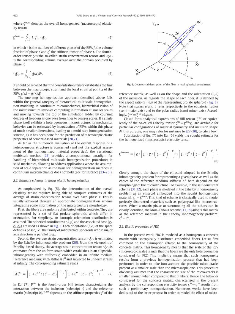
Fig. 3. Geometrical description of the fiber in local spherical coordinates.
462 V.F.P. Dutra et al. / Cement and Concrete Research 40 (2010) 460–472
where C˜
hom denotes the overall homogenized (macroscopic) elastic-ity tensor
˜Chom = ∑
n
r=1fr˜cr : ⟨
˜A⟩r ð5Þ
in which n is the number of different phases of the REV, fr the volumefraction of phase r and c
˜
r the stiffness tensor of phase r. The fourth-order tensor A
˜is the so-called strain concentration tensor and bA
˜Nr
is the corresponding volume average over the domain occupied byphase r:
⟨˜A⟩r =
1Vr
∫Vr
˜Að xÞdV : ð6Þ
It should be recalled that the concentration tensor establishes the linkbetween the macroscopic strain and the local strain at point x of theREV: ε(x)=A
˜(x):E .
The one-step homogenization approach described above fallswithin the general category of hierarchical multiscale homogeniza-tion modeling. In continuum micromechanics, hierarchical vision ofthe microstructure involves computing information at smaller scalesand moving towards the top of the simulation ladder by coursingdegrees of freedom as one goes from finer to coarser scales. If a singlephase itself exhibits a heterogeneous microstructure, its mechanicalbehavior can be estimated by introduction of REVs within this phaseof much smaller dimensions, leading to a multi-step homogenizationscheme, as it has been done for the prediction of macroscopic elasticproperties of cement-based materials [20,21].
As far as the numerical evaluation of the overall response of aheterogeneous structure is concerned (and not the explicit assess-ment of the homogenized material properties), the variationalmultiscale method [22] provides a computational paradigm forhandling of hierarchical multiscale homogenization procedures insolid mechanics, allowing to address applications where the assump-tion of scale separation as the basis for homogenization methods incontinuum micromechanics does not hold (see for instance [23–25]).
2.2. Estimate schemes in linear elastic homogenization
As emphasized by Eq. (5), the determination of the overallelasticity tensor requires being able to compute estimates of theaverage of strain concentration tensor over each phase r. This isusually achieved through an appropriate homogenization schemeintegrating some information on the microstructure morphology.
First, the fibers are randomly distributed within concrete. They arerepresented by a set of flat prolate spheroids which differ inorientation. For simplicity, an isotropic orientation distribution isassumed. The spherical coordinates (r,θ,φ) and the associated base (er,eθ, eφ) are used as shown in Fig. 3. Each orientation (θ,ϕ) of the spacedefines a phase, i.e., the family of solid prolate spheroids whose majoraxis direction is parallel to e r.
Second, the average strain concentration tensor bA˜Nr is estimated
by the Eshelby inhomogeneity problem [26]. From the viewpoint ofEshelby-based theory, the average strain concentration tensor bA
˜Nr is
estimated from the uniform strain which establishes in an ellipsoidalinhomogeneity with stiffness c
˜
r embedded in an infinite medium(reference medium) with stiffness c
˜
0 and subjected to uniform strainsat infinity. The corresponding estimate reads
⟨˜A⟩estr =
˜1 +
˜P0;r : ð
˜cr �
˜c0Þ
� �−1: ⟨ ˜
1 +˜P0 : ð
˜c �
˜c0Þ
� �−1
⟩−1
: ð7Þ
In Eq. (7), P˜
0,r is the fourth-order Hill tensor characterizing theinteraction between the inclusion (subscript r) and the referencematrix (subscript 0). P 0,r depends on the stiffness properties c0 of the
˜
reference matrix, as well as on the shape and the orientation (θ,ϕ)of the inclusion. As regards the shape of each fiber, it is defined bythe aspect ratio α=a/b of the representing prolate spheroid (Fig. 3).Note that scalars a and b refer respectively to the equatorial radius(semi-major axis) and to the polar radius (semi-minor axis). Accord-ingly, P
˜
0,r=P˜
0,r (θ,φ,α).Closed-form analytical expressions of Hill tensor P
˜
0,r, or equiva-lently of the so-called Eshelby tensor S
˜
0,r=P˜
0,r:c˜, are available for
particular configurations of material symmetry and inclusion shape.At this purpose, one may refer for instance to [27–30], to cite a few.
Substitution of Eq. (7) into Eq. (5) yields the sought estimate forthe homogenized (macroscopic) elasticity tensor
˜Chom;est = ⟨ ˜c :
˜1 +
˜P :
˜c �
˜c0
� �� �−1
⟩ : ⟨ ˜1 +
˜P0 :
˜c �
˜c0
� �� �−1
⟩−1
:
ð8Þ
Clearly enough, the shape of the ellipsoid adopted in the Eshelbyinhomogeneity problem for representing a given phase, as well as thechoice of the reference medium stiffness c 0 both depend on themorphology of the microstructure. For example, in the self-consistentscheme [31,32], each phase is modeled in the Eshelby inhomogeneityproblem as an ellipsoid embedded into the sought homogenizedmaterial: c
˜
0=C˜
hom. This kind of scheme is classically used to modelperfectly disordered materials such as polycrystal-like microstruc-tures. When a matrix phase m surrounding all the others can beclearly identified, the Mori–Tanaka scheme [17,18] adopts this matrixas the reference medium in the Eshelby inhomogeneity problem:c˜
0=c˜
m.
2.3. Elastic properties of FRC
In the present work, FRC is modeled as a homogenous concretematrix with isotropically distributed embedded fibers. Let us firstcomment on the assumption related to the homogeneity of theconcrete matrix. This homogeneity means that the scale of the REV(microscopic scale) is such that the fibers are the only heterogeneitiesconsidered for FRC. This implicitly means that such homogeneityresults from a previous homogenization process that had beenperformed in order to take into account the possible micro-crackspresent at a smaller scale than the microscopic one. This procedureobviously assumes that the characteristic size of the micro-cracks issmaller enough when compared to that of fibers. Hence, the behaviorconsidered for the concrete matrix, characterized in the presentanalysis by the corresponding elasticity tensor c
˜
0=c˜
m results fromsuch a preliminary homogenization. Numerous works have beendedicated to the latter process in order to model the effect of micro-

463V.F.P. Dutra et al. / Cement and Concrete Research 40 (2010) 460–472
cracks on the overall elastic properties of a material. For this purpose,one may refer for instance to [12,33–37], to cite a few.
Owing to the matrix–inclusion morphology of FRC, the Mori–Tanaka scheme can be used to estimate the homogenized stiffnesstensor. Accordingly, Eq. (8) writes for a uniform orientation distri-bution of fibers
˜Chom
;MT = fð1−f Þ˜cm + f
˜cf : ⟨ ˜
1 +˜Pm;α :
˜cf−
˜cm
� �� �−1
⟩fibersg: f 1−fð Þ
˜1 + f ⟨ ˜
1 +˜Pm;α :
˜cf−
˜cm
� �� �−1
⟩fibersg−1
ð9Þ
with
⟨ 1 + Pm;α : c f−cm� �h i−1⟩fibers = ∫
2π
φ=0
∫π
θ=0 ˜1 +
˜Pm;αðθ;ϕÞ :
˜c f−
˜cm
� �� �−1 sinθ4π
dθdϕ
ð10Þ
where f denotes the volume fractions of fibers, c˜
f the stiffness tensorof fibers and P
˜
m,α is the Hill tensor for prolate spheroid with aspectratio α.
Assumption of elastic isotropy for both concrete matrix and fibersimplies the elastic isotropy of FRC at the macroscopic level. Thehomogenized elasticity tensor C
˜
hom,MT can therefore be completelydefined by means of the homogenized bulk modulus Khom and shearmodulus Ghom. These coefficients depend on the elastic modulus ofconcrete matrix (km,gm) and fibers (kf,gf), as well on the volumefraction f and aspect ratio α of fibers. The analytical expressions ofKhom and Ghom are obtained from Eqs. (9) and (10) through theevaluation of double integral terms, which can be achieved makinguse of a formal software, such as the MAPLE software. Theseexpressions are provided in the Appendix for the particular caseα=a/b→+∞, that is the case where the diameter parallel to the axisof revolution is considerably larger than the diameter perpendicularto the axis of revolution.
The effect of the aspect ratio of steel fibers on elasticity of FRC hasbeen extensively investigated [7–9]. It has been found, that for volumefractions of fiber ranging within usual values (f≤5%), the aspect ratioof fibers have a small influence on the elastic properties of the steelfiber reinforced concrete. Considering several values for the aspectratio αa{10, 40, 80, 100, +∞}, a parametric study has been carried(for sake of shortness, this study is not developed here). The micro-mechanical model predictions in terms of Khom and Ghom confirmedthat the value of α very slightly affects these moduli. In particular, asfar as the elastic properties of steel reinforced concrete are concerned,one may reasonably consider an infinite value for α.
An important aspect of the behavior of FRC is related to the impactof fibers' nature on the overall properties. Table 1 shows the elasticproperties of some typical fibers.
The influence of elastic properties of the reinforcing fibers is quitenotable as emphasized by the results displayed in Figs. 4 and 5.
Table 1Elastic properties of concrete matrix and different types of fibers.
Fiber Poisson ratio v Young modulusE (MPa)
Bulk modulusk (MPa)
Shear modulusg (MPa)
Steel 0.30 210,000 175,000 80,769.23Aramid 0.35 62,000 68,888.9 22,963Carbon 0.20 380,000 211,111.1 158,333.3Polypropylene 0.30 4000 3333.3 1538.5Glass AR 0.22 80,000 47,619 32786.9Concrete 0.20 31,000 17,222.2 12,916.7
2.4. Comparison with experimental results
The micromechanical predictions of FRC elastic properties using aresults Mori–Tanaka scheme are compared herein to available exper-imental results performed on steel fiber reinforced concrete. The valuesof Young modulus and Poisson ratio of the composite components asprovided in the experimental studies are listed in Table 2.
In Thomas andRamaswamy's [8] experiments, the aspect ratio of theused steel fibers was α=55 and several volume fractions were testedfa{0.5%,1%,1.5%}. Figs. 6 and 7 respectively display the Mori–Tanakaestimates of Ehom and vhom, together with the experimental results.
The Ashour et al. experiments [7] correspond to steel fiberswith steelfiberswith an aspect ratio ofα=75 and fa{0.5%, 1%}, whileα=100 andfa{1%, 1.5%, 2.5%} in the tests performed by Williamson [38]. Thecomparison of the micromechanical estimates of the homogenizedYoungmoduluswith the experimental results are shown in Figs. 8 and 9.
As it appears from the above figures, the Mori–Tanaka estimatesprove to be slightly lower than the measured values provided in thementioned experimental works [7,8,38]. A good agreement is obtainedand the consistencywith experimental data can be termed as reasonable.The discrepancy observed between the micromechanical predictions ofEhom and the experimental results remains lower than 10%.
Fig. 4. Influence of reinforcing fiber type on the homogenized bulk modulus of FRC.
Fig. 5. Influence of reinforcing fiber type on the homogenized shear modulus of FRC.

Table 2Material properties of steel fiber and concrete.
Fiber Young modulus E (MPa) Poisson ratio (v)
Thomas and Ramaswamy [8]Steel fiber 210,000 0.300Concrete 35 MPa 28,700 0.182C35Concrete 65 MPa 37,500 0.201C65Concrete 85 MPa 41,700 0.210C85
Ashour et al. [7]Steel fiber 210,000 0.300Normal Strength Concrete NSC 24,612 0.200Medium Strength Concrete MSC 35,443 0.200High Strength Concrete HSC 38,423 0.200
Williamson [38]Steel fiber 200,000 0.300Concrete 20,802 0.2081
Fig. 8. Young modulus: Mori–Tanaka estimate and experimentally measured value [7].
464 V.F.P. Dutra et al. / Cement and Concrete Research 40 (2010) 460–472
2.5. Finite element numerical simulations
In order to assess the accuracy of the Mori–Tanaka estimates, theconcentration problem (Eq. (4)) is now solved numerically throughthe implementation of a finite element (FE) method.
For sakeof simplicity, a cubic REVof side l is considered. Owing to themacroscopic isotropy of FRC, the restriction of the analysis to a loading
Fig. 6. Young modulus estimated by a Mori–Tanaka scheme and experimentallymeasured from [8].
Fig. 7. Poisson ratio estimated by a Mori–Tanaka scheme and experimentally measuredfrom [8].
mode defined by uniaxial compression is sufficient to obtain the overallelastic properties. Hence, a macroscopic stress ∑=−∑l e1⨂ e1 with∑l≥0 is applied to the REV (Fig. 10). It is recalled that the scaleseparation condition ensures the equivalence between homogeneousboundary strain and stress conditions on the REV [39]. Owing to thesymmetry conditions, only an eighth of the REV geometry, withappropriate boundary conditions as shown in Fig. 10, is considered forthe numerical analysis.
Twenty nodded quadratic hexahedral elements were used for theconcrete discretization of the concrete matrix geometry.
As regards the reinforcement components, the fibers are randomlygenerated and embedded within the concrete matrix finite elements.It is recalled that perfect bonding is assumed between fibers andconcrete matrix. We herein refer to the so-called “embedded model”[40] in which each fiber has the same kinematics than the coincidentpoints of the embedding concrete matrix finite element. Actually, thecontribution of the fiber is expressed by an additional term increasingthe stiffness of the embedding element. In other terms, the fibers actin the “embedded model” as stiffener elements for the medium.
The spatial distribution and orientation of fibers are randomlygenerated bymeans of a specific procedure using the intrinsic functionRAN of Fortran programming language.
Once the finite element displacement solution is obtained, themacroscopic strain is computed by means of surface integrals asindicated in Eq. (2). It is expected that
E = −El e1⊗ e1 + Etðe2⊗ e2 + e3⊗ e3Þ with El; Et≥0: ð11Þ
Fig. 9. Young modulus: Mori–Tanaka estimate and experimental data [38].

Fig. 10. REV under uniaxial compression considered for the FE simulations.
465V.F.P. Dutra et al. / Cement and Concrete Research 40 (2010) 460–472
The homogenized elastic parameters are then obtained byEhom=∑l/El and vhom=Et/El.
In the objective to qualitatively address the scale effect, two valuesfor the REV side l=20, 40cm as well as two values for the fiber lengthd=1, 3 cm have been considered in the numerical study. The valuesadopted for the aspect ratio and volume fraction of fibers rangebetween 10–100 and 0.5%–5%, respectively.
For each of the above configuration defined by the set {l, d, α, f},several random generated distributions of fibers have been consid-ered, and the average values of computed Ehom and vhomwere retainedas numerical estimates for the homogenized elastic parameters.
The numerical results are given in Tables 3 and 4, where the Mori–Tanaka predictions are also reported. It is noted that Ehommean and vhommean
stand for the mean values of the effective Young modulus and Poissonratio obtained from the FE simulations, SD and CV are the corre-sponding standard deviation and coefficient of variation.
As it clearly appears from the above results, the micromechanicalpredictions are very close to the FE numerical solutions. Thisemphasizes the consistency of the Mori–Tanaka scheme to estimatethe elastic properties of FRC. In addition even though the conditiond≪ l necessary for scale separation is roughly satisfied for theadopted values of d and l, the obtained results seem to be lowsensitive to the value of ratio d/l, at least for the considered data. Thisjustifies that the volume of FRC tested in the numerical simulation hasthe status of REV.
RemarkClearly enough, addition of steel fibers in amounts as small as
those commonly used for FRC has a negligible effect on the effectiveelastic properties. From a practical point of view, computing theeffective elasticity of FRC is not in itself a relevant task. However, this
Table 3FE element calculations and Mori–Tanaka prediction of the homogenized Young modulus o
Fiber d=3 cm
REV l=20 cm l=40 cm
α f(%) Young modulus Young modulus
Ehommean (MPa) SD CV E (MPa)
10 0.513 3252.19 13.75 0.0042 3252.295 3363.14 14.80 0.0044 3363.62
40 3 3245.41 4.84 0.0015 3245.515 3353.86 5.46 0.0016 3353.91
80 3 3245.37 1.94 0.00065 3354.28 1.98 0.0006
100 3 3247.37 1.85 0.00065 3353.88 1.94 0.0006
is a necessary step for further upscaling towards the formulation of aconsistent micromechanical model describing the overall elastoplasticbehavior of FRC.
3. Non-ageing viscoelastic behavior of FRC
Under constant load, a concrete specimen first exhibits instanta-neous elastic deformation then followed by a slow further increase ofdeformation in time, corresponding to concrete creep phenomenon.Incorporation of fibers such as steel fibers in concrete reduces themagnitude of creep deformation and associated damage, as has beenwell experimentally evidenced by Mangat and Azari [41]. The mech-anism at the basis of the effect of fiber on matrix creep strain which isfrequently invoked relies on the assumption that shear stress is inducedat the fiber/matrix interface. Fibers do provide restraint to the slidingaction of the matrix relative to the fiber due to the flow component ofcreep.
However, up to now, few works have been dedicated to linkingmacroscopic FRC creep behavior to composite micromechanics.Furthermore, the models developed in this context are essentiallyrestricted to uniaxial creep of FRC [41,42].
This section is devoted to the investigation of macroscopic non-ageing viscoelastic properties of FRC. Basically, the approach consistsin taking advantage of elastic homogenization in Laplace (or Laplace–Carson) transform framework and making use of the correspondenceprinciple (see for instance [43,44]). Formally, the concentrationproblemto be solved for non-ageing viscoelastic constitutive materials isidentical to the elastic casedefinedby Eq. (4). The constitutive equationsat the macroscopic scale are therefore obtained by inverse Laplace (orLaplace–Carson) transform.
f FRC.
d=1 cm Mori–Tanaka
l=20 cm l=40 cm
Young modulus Young modulus
Ehommean (MPa) SD CV E (MPa) E (MPa)
3105.84 0.81 0.00026 3106.56 3129.423134.53 1.83 0.00058 3132.55 3159.033248.33 3.16 0.00097 3279.513366.44 2.68 0.00080 3403.31
3293.723427.133295.243429.683295.463430.05

Table 4Homogenized Poisson ration of FRC: FE calculations and Mori–Tanaka predictions.
Fiber d=3 cm d=1 cm Mori–Tanaka
REV l=20 cm l=40 cm 20 cm 40 cm
α f(%) Poisson ratio Poisson ratio Poisson ratio Poisson ratio
νhommean SD CV ν νhom
mean SD CV ν v
10 0.5 0.203 0.00009 0.0004 0.204 0.2001 0.205 0.00011 0.0006 0.205 0.2013 0.209 0.0012 0.0059 0.209 0.209 0.00013 0.0006 0.2035 0.214 0.0013 0.0060 0.214 0.214 0.00024 0.0011 0.205
40 3 0.209 0.0002 0.0011 0.209 0.2035 0.213 0.0004 0.0017 0.213 0.205
80 3 0.209 0.0002 0.0009 0.2035 0.213 0.0001 0.0003 0.205
100 3 0.209 0.0001 0.0005 0.2035 0.213 0.0002 0.0010 0.205
Fig. 11. Zener Model for uniaxial non-ageing viscoelastic behavior of concrete matrix.
466 V.F.P. Dutra et al. / Cement and Concrete Research 40 (2010) 460–472
In non-ageing viscoelasticity, the local stress tensor in the REV isrelated to the strain history by means of the hereditary Boltzmannintegral representation
σð x; tÞ =˜cð xÞ ∘ ε ð xÞ = ∫
+∞
−∞˜cð x; t−τÞ : ε ð x;τÞdτ ð12Þ
where c˜refers to the fourth-order relaxation modulus tensor and
ε˙ =∂ε/∂τ is understood in sense of distribution in order to account forpossible discontinuities in time. The argument ‘t’ accounts for theinstantaneous response of the viscoelastic material while theargument ‘t’ stands for the whole past history of ε (the dependenceon τ characterizes the delayed response).
The indication of spatial dependence, that is, the dependence onthe position vector x will be omitted in the sequel.
Recalling that the Carson–Laplace transform of function F(t) isdefined as
F⁎ðpÞ = p ∫+∞
−∞Fðt−τÞe−ptdt ð13Þ
so that the viscoelastic relationship writes in terms of Carson–Laplacetransforms
σ ⁎=˜c⁎ : ε
⁎ ð14Þ
which formally expresses anelastic type relationship in Carson–Laplacespace. The elastic homogenization procedure carried out in Section 2 aswell as related results hold in terms of Carson–Laplace transform fields.The macroscopic stress and strain transforms are related through∑____ ⁎=C
˜
hom⁎:E⁎ in which C˜
hom⁎ represents the Carson–Laplace trans-form of the macroscopic elasticity tensor. In particular, the Carson–Laplace transform of theMori–Tanaka estimate C
˜
hom,MT⁎ can be used asapproximation of C
˜
hom⁎ (i.e., C˜
hom⁎≈C˜
hom,MT⁎).To go further, we shall first specify the viscoelastic behavior of each
constituent of FRC.
3.1. Behavior of concrete matrix and steel fibers
As a first approximation, the uniaxial non-ageing viscoelasticbehavior of concrete matrix is described by the Zener rheologicalmodel [44,45] shown in Fig. 11. This simple and commonly usedmodel for linear viscoelastic solid consists in the association in seriesof a spring (stiffness E1) and a Kelvin element with spring stiffness E2and dashpot viscosity η. Even though this model is conceptually verysimple, it reasonably describes the main expected characteristics ofthe response under creep and relaxation observed experimentally forconcrete [43,46].
The relaxation compliance Ezener(t) associated to the Zener modelreads
EzenerðtÞ = E1E1 + E2
ðE2 + E1e−t =τr Þ ð15Þ
where τr=η
E1 + E2is the relaxation characteristic time. It is observed
that Ezener(0)=E1 and Ezenerð+∞Þ= E1E2E1 + E2
respectively refer to theinstantaneous and asymptotic relaxation moduli.
To describe the three-dimensional non-ageing viscoelastic behaviorof isotropic concretematrix, the relaxationmodulus under tensile stressis first approximated by the Zener relaxation compliance (Eq. (15)),while a constant Poisson ratio vm is adopted [47–49].
EmðtÞ = EzenerðtÞHðtÞ ; νmðtÞ = νmHðtÞ ð16Þ
where t→H(t) is the Heaviside step function. The stiffness parametersof themodel are identified by observing that E1 represents the elastic in-stantaneous stiffness, while the asymptotic relaxation modulus E(+∞)ranges between 3 and 5 times the instantaneous stiffness E1, dependingon certain parameters such as the quality of concrete, humidity andtemperature [45,50,51]. As regards the viscosity coefficient η, its valuemay be evaluated from the value of the characteristic time in relaxationτr, which usually ranges between 100 and 300 days [45,51,52].
Finally, the analysis is restricted herein to steel fibers, for which thedelayed effects can be neglected at usual temperatures. Accordingly, alinear elastic behavior is adopted for fibers, E f and v f being the Youngmodulus and Poisson ratio of steel, respectively.

Fig. 12. Model-predicted creep compliance bulk for steel (FRC) for two values of fibervolume fraction.
467V.F.P. Dutra et al. / Cement and Concrete Research 40 (2010) 460–472
3.2. Homogenized viscoelastic properties of FRC
As mentioned in the previous section, we first proceed to elastichomogenization in the space of Carson–Laplace transforms. The initialstep is to compute the transforms of the bulk and shear moduli ofconcrete (km⁎,gm⁎), and of steel (k f⁎,g f⁎).
The correspondence principle indicates that the Carson–Laplacetransforms of the homogenized bulk and shear moduli of FRC areformally obtained by replacing in the expressions of Khom and Ghom thebulk and shear moduli of FRC components by their Carson–Laplacetransforms. For simplicity, we shall restrict the subsequent analysis tothe situation of fibers with infinite value for the aspect ratio (α→+∞).Hence, referring to Eqs. (A1) and (A4) of the Appendix, one has
Khom⁎ =NKðkm⁎
; gm⁎; kf ⁎
; gf ⁎; f ÞDKðkm⁎; gm⁎; kf ⁎; gf ⁎; f Þ ð17Þ
Ghom⁎ =NGðkm⁎
; gm⁎; kf⁎
; gf ⁎; f ÞDGðkm⁎; gm⁎; kf ⁎; gf ⁎; f Þ ð18Þ
The crucial step of such a viscoelastic homogenization process lies inthe ability to compute the Carson–Laplace inverse transform of Eqs.(17) and (18). Generally, such an inverse transform is achieved bymeans of numerical procedures such as those given in Abate andWhitt [53].
In the present situation, the particular structure of Eqs. (17) and(18) makes it possible to derive analytically the expression of therelaxation moduli Khom(t) and Ghom(t). The latter moduli can formallybe written as
KhomðtÞ = Q0 + ∑2
j=1
Qj
qjð1−e−qjtÞ
" #HðtÞ ð19Þ
and
GhomðtÞ = R0 + ∑4
j=1
Rj
rjð1−e−rjtÞ
" #HðtÞ ð20Þ
where coefficients Qj, Rj, qj and rj are known functions of E1, E2, η, vm,Ef, vfand f.
The above viscoelastic behavior of FRC is illustrated below. Theselect data corresponding to the usual concrete and steel fibers aregiven in Table 5. The parameters of the Zener model describing theviscoelastic behavior of concrete are E1=31 GPa, E2=15.43 GPa,η=4650 GPa×days. The fact that these model parameters areconsidered as constant is consistent with the approximation of non-ageing concrete behavior. It is observed that the latter could reasonablybe justified for instance if concrete is loaded at advanced age [46].
The variations in time of the creep compliance function in bulk JhomK
(t) and creep compliance in shear JhomG (t) are displayed in Fig. 12 andFig. 13, respectively. It should be recalled that these functions arerelated to Khom (t) and Ghome(t) in the Carson–Laplace domain through
Table 5Viscoelastic model data.
Concrete Instantaneous relaxation modulus Em(0) 31,000 MPaAsymptotic relaxation modulus εm(+∞) 10,300 MPaRelaxation time τr 100 daysPoisson ratio vm 0.2
Steel Young modulus Ef 210,000 MPaPoisson ratio vf 0.3
Jhom⁎K =1/Khom⁎ and Jhom⁎
G =1/Ghom⁎. Two values commonly used forsteel (FRC) have been considered: f=1% and f=5%.
As shown by Figs. 12 and 13, the addition of steel fibers
– does not significantly affect the elastic instantaneous properties;– does provide restraint to the deformation of the concrete matrix
along the fiber matrix interfacial bond.
These observations are consistent with previous works [41,54].Besides, these figures clearly show that the reinforcing effect due tofibers increases with time. Finally, it also appears from these figuresthat the so-called ‘memory effects’, generally induced by homogeni-zation (see for example [55]), are not significant in the present case asit can be illustrated trough a comparison between the relaxationcharacteristic times of concrete and homogenized materials. Indeed,the characteristic time for the variations of Ghom is about 102 dayswhereas it is equal to 100days for the considered concrete. This smalldifference is attributed to the particular viscoelastic model consideredfor concrete as well as to the selected data. It is likely that the memoryeffects would be more important if the amount of fiber increases.
Fig. 13. Model-predicted creep compliance in shear for steel FRC for two values of fibervolume fraction.
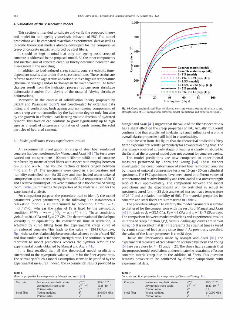
Fig. 14. Creep strain of steel fiber reinforced concrete versus loading time at a stress/strength ratio of 0.3: comparison between model predictions and experiments [41].
468 V.F.P. Dutra et al. / Cement and Concrete Research 40 (2010) 460–472
4. Validation of the viscoelastic model
This section is intended to validate and verify the proposed theoryand model for non-ageing viscoelastic behavior of FRC. The modelpredictions will be compared to available experimental data as well asto some theoretical models already developed for the compressivecreep of concrete matrix reinforced by steel fibers.
It should be kept in mind that only non-ageing basic creep ofconcrete is addressed in the proposedmodel. All the other componentsand mechanisms of concrete creep, as briefly described hereafter, aredisregarded in the modeling.
In addition to load-induced creep strains, concrete exhibits time-dependent strains also under free-stress conditions. These strains arereferred to as shrinkage strains and arise due to changes in temperature(thermal shrinkage) and/or to changes in the water content. The latterchanges result from the hydration process (autogeneous shrinkagedeformation) and/or from drying of the material (drying shrinkagedeformation).
Moreover, in the context of solidification theory proposed byBažant and Prasannan [56,57] and corroborated by extensive datafitting and verification, both ageing and non-ageing components ofbasic creep are not controlled by the hydration degree only, but alsoby the growth in effective load-bearing volume fraction of hydratedcement. This fraction can continue to grow significantly up to highages as a result of progressive formation of bonds among the solidparticles of hydrated cement.
4.1. Model predictions versus experimental results
An experimental investigation on creep of steel fiber reinforcedconcrete has been performed by Mangat and Azari [41]. The tests werecarried out on specimens 100 mm×100 mm×500 mm of concretereinforced by means of steel fibers with aspect ratio ranging betweenα=56 and α=61. The volume fraction of fibers ranged betweenf=0 and f=3%. The specimens were cured in a temperature andhumidity controlled room for 28 days and then loaded under uniaxialcompression up to a stress/strength ratio of 0.3. A temperature of 20 °Cand a relative humidity of 55%weremaintained in the controlled curingroom. Table 6 summarizes the properties of the materials used for theexperimental analysis.
For comparison purpose, the procedure used to identify the modelparameters (Zener parameters) is the following. The instantaneousrelaxation modulus is determined by condition Ezenerð0Þ = E1= σc = εmð0Þ, whereas the value of E2 is fixed by the asymptoticcondition Ezenerð + ∞Þ = E1E2
E1 + E2= σc = εmð + ∞Þ. These conditions
yield E1=20.4 GPa and E2=7.7 GPa. The determination of the dashpotviscosity η, or equivalently the characteristic time in relaxation, isachieved by curve fitting from the experimental creep curve ofunreinforced concrete. This leads to the value η=184.1 GPa×days.Fig. 14 shows the relationship between uniaxial creep strain of steel FRCand time under load at 0.3 stress/strength ratio. The continuous curvesrepresent to model predictions whereas the symbols refer to theexperimental points obtained by Mangat and Azari [41].
It is first recalled that all the theoretical model predictionscorrespond to the asymptotic value α→+∞ for the fiber aspect ratio.The relevancy of such a model assumption seems to be justified by theexperimental measures. Indeed, the experimental results provided in
Table 6Material properties for creep tests by Mangat and Azari [41].
Concrete Instantaneous elastic strain εm(0) 365·10−6
Asymptotic creep strain εm(+∞) 1335·10−6
Poisson ratio vm 0.2Steel fiber Young modulus Ef 210,000 MPa
Poisson ratio vf 0.3
Mangat and Azari [41] suggest that the value of the fiber aspect ratio αhas a slight effect on the creep properties of FRC. Actually, this resultconfirms that that established in elasticity (small influence of α on theoverall elastic properties) still hold in viscoelasticity.
It can be seen from this figure that the theoretical predictions fairlyfit the experimental results, particularly for advanced loading time. Thediscrepancy observed at early stages of loading is clearly attributed tothe fact that the proposed model does not account for concrete ageing.
The model predictions are now compared to experimentalmeasures performed by Chern and Young [54]. These authorsinvestigated the creep performance of steel fiber reinforced concreteby means of uniaxial compressive tests on 15 cm×30 cm cylindricalspecimens. The FRC specimens have been cured at different values oftemperature and relative humidity and then loaded at a stress/strengthratio of 0.25 approximately. The comparison between the modelpredictions and the experiments will be restricted in sequel tospecimens cured for t′=28 days and tested in a room at a temperatureof 23 °C and a relative humidity of 50%. The material properties forconcrete and steel fibers are summarized in Table 7.
The procedure adopted to identify the model parameters is similarto that used for the comparisons with the results of Mangat and Azari[41]. It leads to E1=23.5 GPa, E2=4.4 GPa and η=184.7 GPa×days.The comparison between model predictions and experimental resultsin terms of creep function J(t′,t) versus loading age curves are shownin Fig. 15. It is recalled that J(t′,t) represents the strain at time t causedby a unit sustained load acting since time t′. As previously specified,the value of the latter parameter is t′=28 days.
Unlike the observations made by Mangat and Azari [41], theexperimentalmeasures of creep function obtained by Chern and Young[54] are very close for f=1% and f=2%. The above figure suggests thattheproposedmodel predictionsunderestimate the restrainingeffect onconcrete matrix creep due to the addition of fibers. This questionremains however to be confirmed by further comparisons withexperimental data.
Table 7Concrete and fiber properties for creep tests by Chern and Young [54].
Concrete Instantaneous elastic strain εm(0) 290·10−6
Asymptotic creep strain εm(+∞) 1833·10−6
Poisson ratio vm 0.2Steel fiber Young modulus Ef 210,000 MPa
Poisson ratio vf 0.3
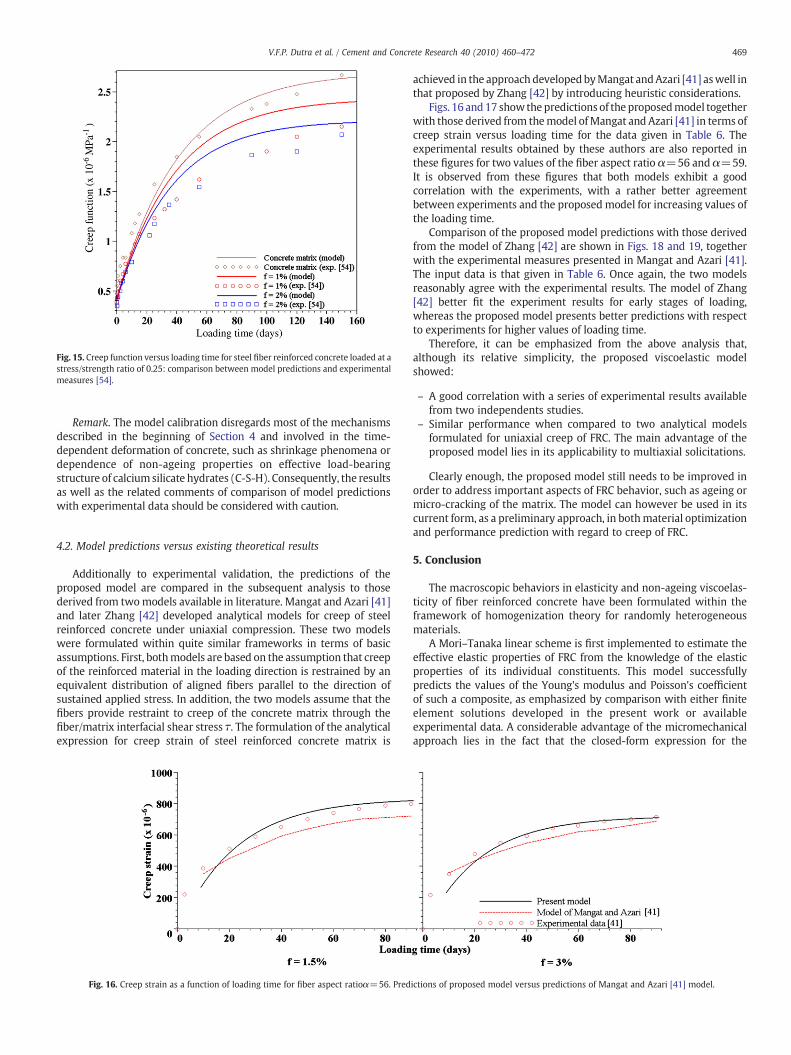
Fig. 15. Creep function versus loading time for steel fiber reinforced concrete loaded at astress/strength ratio of 0.25: comparison between model predictions and experimentalmeasures [54].
469V.F.P. Dutra et al. / Cement and Concrete Research 40 (2010) 460–472
Remark. The model calibration disregards most of the mechanismsdescribed in the beginning of Section 4 and involved in the time-dependent deformation of concrete, such as shrinkage phenomena ordependence of non-ageing properties on effective load-bearingstructure of calciumsilicate hydrates (C-S-H). Consequently, the resultsas well as the related comments of comparison of model predictionswith experimental data should be considered with caution.
4.2. Model predictions versus existing theoretical results
Additionally to experimental validation, the predictions of theproposed model are compared in the subsequent analysis to thosederived from twomodels available in literature. Mangat and Azari [41]and later Zhang [42] developed analytical models for creep of steelreinforced concrete under uniaxial compression. These two modelswere formulated within quite similar frameworks in terms of basicassumptions. First, bothmodels are based on the assumption that creepof the reinforced material in the loading direction is restrained by anequivalent distribution of aligned fibers parallel to the direction ofsustained applied stress. In addition, the two models assume that thefibers provide restraint to creep of the concrete matrix through thefiber/matrix interfacial shear stress τ. The formulation of the analyticalexpression for creep strain of steel reinforced concrete matrix is
Fig. 16. Creep strain as a function of loading time for fiber aspect ratioα=56. Pred
achieved in the approach developedbyMangat andAzari [41] aswell inthat proposed by Zhang [42] by introducing heuristic considerations.
Figs. 16 and17 showthepredictions of the proposedmodel togetherwith those derived from themodel ofMangat and Azari [41] in terms ofcreep strain versus loading time for the data given in Table 6. Theexperimental results obtained by these authors are also reported inthese figures for two values of the fiber aspect ratio α=56 and α=59.It is observed from these figures that both models exhibit a goodcorrelation with the experiments, with a rather better agreementbetween experiments and the proposed model for increasing values ofthe loading time.
Comparison of the proposed model predictions with those derivedfrom the model of Zhang [42] are shown in Figs. 18 and 19, togetherwith the experimental measures presented in Mangat and Azari [41].The input data is that given in Table 6. Once again, the two modelsreasonably agree with the experimental results. The model of Zhang[42] better fit the experiment results for early stages of loading,whereas the proposed model presents better predictions with respectto experiments for higher values of loading time.
Therefore, it can be emphasized from the above analysis that,although its relative simplicity, the proposed viscoelastic modelshowed:
– A good correlation with a series of experimental results availablefrom two independents studies.
– Similar performance when compared to two analytical modelsformulated for uniaxial creep of FRC. The main advantage of theproposed model lies in its applicability to multiaxial solicitations.
Clearly enough, the proposed model still needs to be improved inorder to address important aspects of FRC behavior, such as ageing ormicro-cracking of the matrix. The model can however be used in itscurrent form, as a preliminary approach, in bothmaterial optimizationand performance prediction with regard to creep of FRC.
5. Conclusion
The macroscopic behaviors in elasticity and non-ageing viscoelas-ticity of fiber reinforced concrete have been formulated within theframework of homogenization theory for randomly heterogeneousmaterials.
A Mori–Tanaka linear scheme is first implemented to estimate theeffective elastic properties of FRC from the knowledge of the elasticproperties of its individual constituents. This model successfullypredicts the values of the Young's modulus and Poisson's coefficientof such a composite, as emphasized by comparison with either finiteelement solutions developed in the present work or availableexperimental data. A considerable advantage of the micromechanicalapproach lies in the fact that the closed-form expression for the
ictions of proposed model versus predictions of Mangat and Azari [41] model.

Fig. 17. Creep strain as a function of loading time for fiber aspect ratio α=59. Predictions of proposed model versus predictions of Mangat and Azari [41] model.
Fig. 18. Creep strain as a function of loading time for fiber aspect ratio α=56. Predictions of proposed model versus predictions of Zhang [42] model.
470 V.F.P. Dutra et al. / Cement and Concrete Research 40 (2010) 460–472
homogenized elastic properties makes it possible to easily analyze theimpact at the macroscopic level of the reinforcement characteristics(fiber stiffness, fiber volume fraction, and fiber aspect ratio).
In the situation, covering in particular the case of loading applied toconcrete at advanced age, where ageing could be neglected for theviscoelastic behavior of concrete, the homogenized behavior of FRC hasbeen determined. Reasoning within the framework of Carson–Laplacetransform, the conjunction of the results previously obtained in elastichomogenization with the correspondence principle allows derivingclosed-form expressions for the homogenized bulk and shear relaxa-tion moduli. The validity of the model has been assessed by mean of
Fig. 19. Creep strain as a function of loading time for fiber aspect ratio α=59
comparison with available experiment results of creep strain of FRCspecimens under compressive load. It should be emphasized that theexperimental results analyzed in this paper clearly indicate no slip onthe matrix–fiber interface, which is compatible with the micromecha-nical model assumptions.
In addition, the model predictions prove to be similar to thosederived from two analytical models formulated in one-dimensionalsetting. The main advantage of the present model lies in its potentialapplicability to FRC under multiaxial solicitation.
In view of a more comprehensive modeling of FRC behavior, anumber of improvements and developments are still necessary. In this
. Predictions of proposed model versus predictions of Zhang [42] model.

471V.F.P. Dutra et al. / Cement and Concrete Research 40 (2010) 460–472
respect, the validation of the homogenized viscoelastic modelformulated in Section 3 through comparison with experimental dataand finite element solutions is a fundamental issue to be addressed. Asregards the theoretical aspect, a key challenge for next futureextensions is to account for ageing. Indeed, the viscoelastic behaviorconcrete exhibits ageing and a specific homogenization procedure isrequired [55], since the reasoning based on Carson–Laplace transformdoes not apply.
Finally, the real task which remains to be done consists in dealingwith non-linear phenomena which are necessary for addressingstrength. Actually, the formulation of the macroscopic strengthproperties of FRC by means of limit analysis homogenizationtechniques is the matter of on-going research.
Appendix A
Expressions of Khom and Ghom for fibers with infinite aspect ratio(α→+∞)Below are provided the analytical expressions of themacroscopic bulk modulus Khomand macroscopic shear modulus Ghom
of FRC, derived from a Mori–Tanaka homogenization scheme. Theaspect ratio of fibers is assumed as infinite, i.e., α→+∞.
First,
Khom =NK ðkm; gm; kf
; g f; f Þ
DKðkm; gm; kf ; gf ; f ÞðA1Þ
where the function NK and DK depend on the elastic properties of thecomponents of FRC as well as on the volume fraction of fibers. Thenumerators in (A1) writes
NK = ð3gm+g f Þ½ð1−f Þkm+ fk f �+3kmk f ðA2Þ
whereas the denominator has the following expression
DK = ð3gm + g f Þ + 3ðf km + ð1−f Þk f Þ ðA3Þ
The macroscopic shear modulus is expressed by
Ghom =NGðkm; gm; kf g;f f ÞDGðkm; gm; kf ; gf ; f Þ
ðA4Þ
where NG = ∑6
i=1ni with
n1 = 9fkmkf ðg f Þ3 ; n2 = 3gmðgf Þ2ð7fgf ðkm+kf Þ+15kmkf ð1+ f Þ+5gf kmÞn3 = ðgmÞ2gf ð35ðgf Þ2ð35+37f Þ+15kmgf ð5+3f Þ+3kf gf ð35+17f Þ+10kmkf ð9−f ÞÞn4 = ðgmÞ3ððg f Þ2ð145+39f Þ+21kmgf ð5−f Þ+3kf gf ð40−19f Þ+45kmkf ð1−f ÞÞn5 = ðgmÞ4ð45kmð1−f Þ+15kf ð1−f Þ+gf ð125−61f ÞÞ ; n6 = 15ðgmÞ5ð1−f Þ
8>>><>>>:
ðA5Þ
and DG = ∑5
i=1di with
d1 = 3kmðgf Þ2ð5gf ð1−f Þ+3kf ð5−4f ÞÞd2 = gmgf ð35ðgf Þ2ð1−f Þ+3kmgf ð25−13f Þ+21kf g f ð5−4f Þ+90kmkf Þd3 = ðgmÞ2ððgf Þ2ð145−73f Þ+15kmgf ð7 + f Þ+12kf gf ð10+3f Þ + 9kmkf ð5+4f ÞÞd4 = ðgmÞ3ð9kmð5+4f Þ+3kf ð5 + 16f Þ+gf ð125+59f ÞÞ ; d5 = ðgmÞ4ð15+49f Þ
8>>><>>>:
ðA6Þ
References
[1] A. Zaoui, Continuum micromechanics: survey, J. Eng. Mech. 128 (2002) 808–816.[2] American Concrete Institute. State-of-the-art report on fiber reinforced concrete,
in: Manual of concrete Practice, 93, Detroit, Michigan, 1996 (ACI 544.1R-96).[3] A. Bentur, S. Mindess, Fibre Reinforced Cementitious Composites, Elsevier Science
Publishers, New York, 1990.[4] P. Casanova, P. Rossi, I. Schaller, Can steel fibers replace transverse reinforcement
in reinforced concrete beams? ACI Mater. J. 94 (5) (1997) 341–354.
[5] Y. Kwak, M.O. Eberhard, W. Kim, J. Kim, Shear strength of steel fiber-reinforcedconcrete beams without stirrups, ACI Struct. J. 99 (2002) 530–538.
[6] C. Cucchiara, L. Mendola, M. Papia, Effectiveness of stirrups and steel fibres as shearreinforcement, Cem. Concr. Compos. 26 (7) (2004) 777–786.
[7] S.A. Ashour, F.F. Wafa, M.I. Kamal, Effect of the concrete compressive strength andtensile reinforcement ratio on the flexural behavior of fibrous concrete beams,Engineering Structures 22 (9) (2000) 1145–1158.
[8] J. Thomas, A. Ramaswamy, Mechanical properties of steel fiber-reinforced concrete,J. Mater. Civ. Eng. 19 (2007) 385–392.
[9] C.D. Atiş, O. Karahan, Properties of steel fiber reinforced fly ash concrete, Constr.Build. Mater. 23 (1) (2009) 392–399.
[10] A.V. Hershey, The elasticity of an isotropic aggregate of anisotropic cubic crystals,Journal of Applied Mechanics 21 (3) (1954) 236–240.
[11] E. Kröner, Self-consistent scheme and graded disorder in polycrystal elasticity,J. Phys. F. Met. Phys. 8 (1978) 2261–2267.
[12] S. Nemat-Nasser, M. Hori, Micromechanics: overall properties of heterogeneousmaterials, Elsevier, North-Holland, 1993.
[13] W.B. Russel, On the effective moduli of composite materials: effect of fiber lengthand geometry at dilute concentrations, Journal of Applied Mathematics andPhysics 24 (1973) 581–600.
[14] R.M. Christensen, K.H. Lo, Solutions for effective shear properties in three phasesphere and cylinder model, J. Mech. Phys. Solids 27 (4) (1979) 315–330.
[15] Y. Huang, K.X. Hu, X. Wei, A. Chandra, A generalized self-consistent mechanicsmethod for composite materials with multiphase inclusions, J. Mech. Phys. Solids42 (1994) 491–504.
[16] P.M. Suquet, Elements of homogenization for inelastic solid mechanics, in: E.Sanchez-Palencia, A. Zaoui (Eds.), Homogenization Techniques for CompositeMedia, Lecture notes in physics No. 272, Springer, New York, 1987, pp. 193–278.
[17] T. Mori, K. Tanaka, Average stress in matrix and average elastic energy of materialswith misfitting inclusions, Acta Metall. 21 (1973) 571–574.
[18] Y. Benveniste, A new approach to the application of Mori–Tanaka's theory incomposite materials, Mech. Mater. 6 (2) (1987) 147–157.
[19] G.J. Weng, The theoretical connection between Mori–Tanaka's theory and theHashin–Shtrikman–Walpole bounds, Int. J. Eng. Sci. 28 (1990) 1111–1120.
[20] F.-J. Ulm, G. Constantinides, F. Heukamp, Is concrete a poromechanics material ? Amultiscale investigation of poroelastic properties, Material and Structures/ConcreteScience Engineering 37 (265) (2004) 43–58.
[21] J. Sanahuja, L. Dormieux, G. Chanvillard, Modelling elasticity of hydrating cementpaste, Cem. Concr. Res. 37 (10) (2007) 1427–1439.
[22] T.J.R. Hughes, G.R. Feijoo, L. Mazzei, J.-B. Quincy, The variationalmultiscalemethod—a paradigm for computational mechanics, Comput. Methods Appl. Mech. Eng. 166(1998) 3–24.
[23] T.I. Zohdi, J.T. Oden, G.J. Rodin, Hierarchical modelling of heterogeneous bodies,Comput. Methods Appl. Mech. Eng. 138 (1996) 273–298.
[24] J.T. Oden, V. Kumar, N. Moes, Hierarchical modelling of heterogeneous solids,Comput. Methods Appl. Mech. Eng. 172 (1999) 3–25.
[25] T. Hettich, A. Hund, E. Ramm, Modeling of failure in composites by X-FEM and levelwithin a multiscale framework, Comput. Methods Appl. Mech. Eng. 197 (5) (2008)414–424.
[26] J.D. Eshelby, The determination of the elastic field of an ellipsoidal inclusion, andrelated problems, Proceedings of the Royal Society of London. Series A 241 (1226)(1957) 376–396.
[27] G. Faivre, Hétérogénéités ellipsoïdales dans unmilieu élastique anisotrope, Journalof Physics 32 (4) (1971) 325–331.
[28] N. Laws, The determination of stress and strain concentrations at an ellipsoidalinclusion in an anisotropic material, J. Elast. 7 (1977) 91–97.
[29] T. Mura, Micromechanics of Defects in Solids, Nijhoff, The Hague, The Netherlands,1987.
[30] A. Suvorov, G. Dvorak, Rate form of the Eshelby and Hill tensors, Int. J. Solids Struct.39 (2002) 5659–5678.
[31] R. Hill, A self-consistent mechanics of composite materials, J. Mech. Phys. Solids 13(4) (1965) 213–222.
[32] B. Budiansky, On the elastic moduli of some heterogeneous materials, J. Mech.Phys. Solids 13 (4) (1965) 223–227.
[33] M. Kachanov, A microcrack model of rock inelasticity — Part I: frictional sliding onmicrocracks, Mech. Mater. 1 (1982) 19–27.
[34] M. Kachanov, A microcrack model of rock inelasticity — Part II: propagation ofmicrocracks, Mech. Mater. 1 (1982) 29–41.
[35] H. Horii, S. Nemat-Nasser, Overall moduli of solids with microcracks: load inducedanisotropy, J. Mech. Phys. Solids 31 (2) (1983) 155–171.
[36] V. Deudé, L. Dormieux, D. Kondo, S. Maghous, Micromechanics approach tononlinear poroelasticity: application to cracked rocks, J. Eng. Mech. ASCE 128 (8)(2002) 848–855.
[37] V. Pensée, D. Kondo, L. Dormieux, A micromechanical analysis of anisotropicdamage in brittle materials, J. Eng. Mech. ASCE 128 (2002) 889–897.
[38] G.R. Williamson, The effect of steel fibers on the compressive strength of concrete,International Symposium on Fiber Reinforced Concrete, SP 44–11, Am. Concr. Inst.(1974) 195–207.
[39] R. Hill, The essential structure of constitutive laws for metal composites andpolycrystals, J. Mech. Phys. Solids 15 (2) (1967) 79–95.
[40] A.E. Elwi, T.M. Hrudey, Finite element model for curved embedded reinforcement,J. Eng. Mech.Div. 115 (4) (1989) 740–754.
[41] P.S. Mangat, M.M. Azari, A theory for the creep of steel fibre reinforced cementmatrices under compression, J. Mater. Sci. 20 (1985) 1119–1133.
[42] J. Zhang, Modeling of the influence of fibers on creep of fiber reinforcedcementitious composite, Compos. Sci. Technol. 63 (2003) 1877–1884.

472 V.F.P. Dutra et al. / Cement and Concrete Research 40 (2010) 460–472
[43] J. Salençon, Viscoélasticité, Presse de l'Ecole Nationales des Ponts et Chaussées,Paris, 1993.
[44] G.J. Creus, Viscoelasticity: Basic Theory and Applications to Concrete Structures,Springer-Verlag, Berlin, 1986.
[45] P.K. Mehta, P.J.M. Monteiro, Concrete: Microstructure, Properties and Materials,McGraw-Hill, New York, 2006.
[46] A. Berthollet, Contribution à la modélisation du béton vis-à-vis du vieillissementet de la durabilité: interaction des déformations de fluage et du comportementnon-linéaire du matériau, PhD Thesis, Ecole doctorale de Mécanique, Energétique,Génie civil et Acoustique, Lyon, 2003.
[47] E.A. Kogan, Creep of concrete under multiaxial compression, Power Technol. andEng. 17 (1983) 448–452.
[48] Z.P. Bažant, Theory of creep and shrinkage in concrete structures: A precis ofrecent developments, in: S. Nemat-Nasser (Ed.), Mechanics Today, AmericanAcademy of Mechanics, vol 2, Pergamon Press, New York, 1975, pp. 1–93.
[49] K.S. Gopalakrishnan, A.M. Neville, A. Ghali, Creep Poisson's ratio of concrete undermultiaxial compression, ACI J. 66 (12) (1969) 1008–1019.
[50] A. Ghali, R. Favre, Concrete Structures: Stresses and Deformations, Chapman andHall, London, 1986.
[51] A.M. Neville, W.H. Dilger, J.J. Brooks, Creep of Plain and Structural Concrete,Construction Press, London, 1983.
[52] Z. P. Bažant, Creep of concrete, in: K.H.J. Buschow et al. (eds.), Encyclopedia ofmaterials: Science and Technology, Elsevier, Amsterdam, Vol. 2C, 2001, 1797–1800.
[53] J. Abate, W. Whitt, A unified framework for numerically inverting Laplacetransforms, INFORMS J Comput 18 (4) (2006) 408–421.
[54] J.C. Chern, C.H. Young, Compressive creep and shrinkage of steel fibre reinforcedconcrete, The International Journal of cement Composites and LightweightConcrete 11 (4) (1989) 205–214.
[55] S. Maghous, G.J. Creus, Periodic homogenization in thermoviscoelasticity: case ofmultilayered media with ageing, Int. J. Solids Struct. 40 (2003) 851–870.
[56] Z.P. Bažant, S. Prasannan, Solidification theory for concrete creep: I. Formulation,J. Eng. Mech. 115 (8) (1989) 1691–1703.
[57] Z.P. Bažant, S. Prasannan, Solidification theory for concrete creep: II. Verificationand application, J. Eng. Mech. 115 (8) (1989) 1691–1703.