Characterization of Multiwalled Carbon Nanotube (MWCNT) Composites in a Waveguide of Square Cross...
8
Characterization of multi-walled carbon nanotube dispersion in resorcinol–formaldehyde aerogels Majid Haghgoo a,b , Ali Akbar Yousefi a , Mohammad Jalal Zohouriaan Mehr a , Alain Celzard c,d , Vanessa Fierro d , Angélique Léonard b , Nathalie Job b,⇑ a Plastic Processing & Engineering Department, Iran Polymer and Petrochemical Institute (IPPI), Tehran, Iran b University of Liège, Laboratory of Chemical Engineering, Institut de Chimie B6a, Sart-Tilman, B-4000 Liège, Belgium c Université de Lorraine, ENSTIB, 27 rue Ph. Seguin, BP 1041, 88051 Epinal cedex 9, France d Institut Jean Lamour, UMR CNRS 7198, ENSTIB, 27 rue Ph. Seguin, BP 1041, 88051 Epinal cedex 9, France article info Article history: Received 22 April 2013 Received in revised form 16 September 2013 Accepted 4 October 2013 Available online 11 October 2013 Keywords: Resorcinol–formaldehyde gel Aerogel Multi-walled carbon nanotube Dispersion Characterization abstract Multi-walled carbon nanotube (MWCNT)/resorcinol–formaldehyde (RF) composite gels were prepared by sol–gel polymerization of RF monomers in a suspension of carbon nanotubes in water, followed by CO 2 supercritical drying. X-ray microtomography showed that the suspensions of MWCNTs were stable and that the distribution of nanotubes throughout the RF matrix was uniform. The level of MWCNT dispersion in the composites was evaluated by microscopic methods (optical microscopy, SEM and TEM). Micro- graphs showed that, at low MWCNT concentration (<0.26 v%), the nanotube bundles were completely exfoliated, leading to a homogeneous material at the nanometer scale. On the contrary, at higher concen- trations, aggregates of MWCNTs with diameters up to 50 lm were observed. N 2 sorption analysis showed that the carbon nanotube aggregation may result in a decrease of BET surface area of the composites. Thermal conductivity of the nanocomposites was measured by TPS hot disk method and the data were consistent with effective medium theory (EMT). At high MWCNT loadings, it was possible to estimate the volume fraction of separated and aggregated carbon nanotubes based on the deviation of the exper- imental conductivity data from EMT predictions. Ó 2013 Elsevier Inc. All rights reserved. 1. Introduction In the last two decades, carbon nanotube (CNT)/polymer com- posites have attracted considerable attention due to their signifi- cantly enhanced properties compared to those of classical composites [1–3]. One of the key factors that determine the final properties of these materials is the dispersion state of the CNTs throughout the polymer matrix. Many reports have been published on this issue. While a homogeneous uniform dispersion of nano- tubes is most often desirable to obtain an optimal nanocomposite [4,5], it is proved that, sometimes, the development of a heteroge- neous network of agglomerated CNTs is preferable, e.g. to attain electrical percolation [2,3,6,7]. CNT-containing aerogels, however, have received less attention [8–10]. Aerogels are a class of highly nanoporous materials with outstanding properties such as high mesopore volume and high specific surface area. Nevertheless, due to their low solid content, and thus low mechanical and transport properties, aerogels do not match the requirements for a proper performance in some applications. Incorporation of CNTs into the gel matrices seems to be a good strategy to improve the physical properties of the composites and broaden the application field of these very inter- esting materials [10,11]. One of the most promising types of aerogels is based on resor- cinol–formaldehyde polymer chains gelled in water. These were first introduced by Pekala [12], and then developed by several re- search groups for various applications [13–15]. These materials are classically prepared by sol–gel polymerization of the mono- mers in an aqueous media, followed by CO 2 supercritical drying. Worsley et al. [7,8,10,11] were the first to prepare a monolithic RF aerogel nanocomposite containing double-walled carbon nano- tubes (DWCNTs). They carried out the sol–gel polymerization of the monomers in surfactant-aided nanotube dispersion in water and reported a uniform dispersion of DWCNTs throughout the polymer matrix after gelation, aging and supercritical drying. The same group also characterized the corresponding carbon/carbon composite after pyrolysis of the DWCNT-containing aerogel and, in a series of papers, showed improved thermal [11] and electrical [10] conductivity with respect to classical carbon aerogels. Although sonication in the presence of surfactant proved to re- sult in a homogeneous CNT dispersion [16,17], the hydrophobic nature and strong Van der Waals interactions of CNTs often 1387-1811/$ - see front matter Ó 2013 Elsevier Inc. All rights reserved. http://dx.doi.org/10.1016/j.micromeso.2013.10.002 ⇑ Corresponding author. Tel.: +32 4 366 3537; fax: +32 4 366 3545. E-mail address: [email protected] (N. Job). Microporous and Mesoporous Materials 184 (2014) 97–104 Contents lists available at ScienceDirect Microporous and Mesoporous Materials journal homepage: www.elsevier.com/locate/micromeso
Transcript of Characterization of Multiwalled Carbon Nanotube (MWCNT) Composites in a Waveguide of Square Cross...

Microporous and Mesoporous Materials 184 (2014) 97–104
Contents lists available at ScienceDirect
Microporous and Mesoporous Materials
journal homepage: www.elsevier .com/locate /micromeso
Characterization of multi-walled carbon nanotube dispersionin resorcinol–formaldehyde aerogels
1387-1811/$ - see front matter � 2013 Elsevier Inc. All rights reserved.http://dx.doi.org/10.1016/j.micromeso.2013.10.002
⇑ Corresponding author. Tel.: +32 4 366 3537; fax: +32 4 366 3545.E-mail address: [email protected] (N. Job).
Majid Haghgoo a,b, Ali Akbar Yousefi a, Mohammad Jalal Zohouriaan Mehr a, Alain Celzard c,d,Vanessa Fierro d, Angélique Léonard b, Nathalie Job b,⇑a Plastic Processing & Engineering Department, Iran Polymer and Petrochemical Institute (IPPI), Tehran, Iranb University of Liège, Laboratory of Chemical Engineering, Institut de Chimie B6a, Sart-Tilman, B-4000 Liège, Belgiumc Université de Lorraine, ENSTIB, 27 rue Ph. Seguin, BP 1041, 88051 Epinal cedex 9, Franced Institut Jean Lamour, UMR CNRS 7198, ENSTIB, 27 rue Ph. Seguin, BP 1041, 88051 Epinal cedex 9, France
a r t i c l e i n f o a b s t r a c t
Article history:Received 22 April 2013Received in revised form 16 September 2013Accepted 4 October 2013Available online 11 October 2013
Keywords:Resorcinol–formaldehyde gelAerogelMulti-walled carbon nanotubeDispersionCharacterization
Multi-walled carbon nanotube (MWCNT)/resorcinol–formaldehyde (RF) composite gels were prepared bysol–gel polymerization of RF monomers in a suspension of carbon nanotubes in water, followed by CO2
supercritical drying. X-ray microtomography showed that the suspensions of MWCNTs were stable andthat the distribution of nanotubes throughout the RF matrix was uniform. The level of MWCNT dispersionin the composites was evaluated by microscopic methods (optical microscopy, SEM and TEM). Micro-graphs showed that, at low MWCNT concentration (<0.26 v%), the nanotube bundles were completelyexfoliated, leading to a homogeneous material at the nanometer scale. On the contrary, at higher concen-trations, aggregates of MWCNTs with diameters up to 50 lm were observed. N2 sorption analysis showedthat the carbon nanotube aggregation may result in a decrease of BET surface area of the composites.Thermal conductivity of the nanocomposites was measured by TPS hot disk method and the data wereconsistent with effective medium theory (EMT). At high MWCNT loadings, it was possible to estimatethe volume fraction of separated and aggregated carbon nanotubes based on the deviation of the exper-imental conductivity data from EMT predictions.
� 2013 Elsevier Inc. All rights reserved.
1. Introduction
In the last two decades, carbon nanotube (CNT)/polymer com-posites have attracted considerable attention due to their signifi-cantly enhanced properties compared to those of classicalcomposites [1–3]. One of the key factors that determine the finalproperties of these materials is the dispersion state of the CNTsthroughout the polymer matrix. Many reports have been publishedon this issue. While a homogeneous uniform dispersion of nano-tubes is most often desirable to obtain an optimal nanocomposite[4,5], it is proved that, sometimes, the development of a heteroge-neous network of agglomerated CNTs is preferable, e.g. to attainelectrical percolation [2,3,6,7].
CNT-containing aerogels, however, have received less attention[8–10]. Aerogels are a class of highly nanoporous materials withoutstanding properties such as high mesopore volume and highspecific surface area. Nevertheless, due to their low solid content,and thus low mechanical and transport properties, aerogels donot match the requirements for a proper performance in some
applications. Incorporation of CNTs into the gel matrices seemsto be a good strategy to improve the physical properties of thecomposites and broaden the application field of these very inter-esting materials [10,11].
One of the most promising types of aerogels is based on resor-cinol–formaldehyde polymer chains gelled in water. These werefirst introduced by Pekala [12], and then developed by several re-search groups for various applications [13–15]. These materialsare classically prepared by sol–gel polymerization of the mono-mers in an aqueous media, followed by CO2 supercritical drying.Worsley et al. [7,8,10,11] were the first to prepare a monolithicRF aerogel nanocomposite containing double-walled carbon nano-tubes (DWCNTs). They carried out the sol–gel polymerization ofthe monomers in surfactant-aided nanotube dispersion in waterand reported a uniform dispersion of DWCNTs throughout thepolymer matrix after gelation, aging and supercritical drying. Thesame group also characterized the corresponding carbon/carboncomposite after pyrolysis of the DWCNT-containing aerogel and,in a series of papers, showed improved thermal [11] and electrical[10] conductivity with respect to classical carbon aerogels.
Although sonication in the presence of surfactant proved to re-sult in a homogeneous CNT dispersion [16,17], the hydrophobicnature and strong Van der Waals interactions of CNTs often

98 M. Haghgoo et al. / Microporous and Mesoporous Materials 184 (2014) 97–104
prevent the complete exfoliation of CNT bundles in the composite[18,19]. In addition, destabilization phenomena can occur throughsome changes of composition, for instance by adding reagents orduring the sol–gel polymerization, as well as by modifying thetemperature. This highlights the complexity of the CNT/RF gel sys-tem. Many synthesis variables may affect the dispersion of theCNTs in the precursor solution, and thus the degree of homogene-ity of the final CNT/RF gel composite [20].
A review of the literature shows that the characterization of theCNT dispersion throughout the RF gel matrix has not been investi-gated in depth yet. Previous works [8,11,12] focused on SEM andTEM images only, but such techniques provide results that arerarely representative of the studied material due to both samplingand required preparation conditions. Moreover, to the best of ourknowledge, no results regarding the characterization of multi-walled carbon nanotubes incorporated in an aerogel medium ashost material are available in the open literature. Compared to sin-gle-walled carbon nanotubes (SWCNTs), MWCNTs show a lowertendency to associate in bundles. As a result, their separation intoindividual nanotubes is easier [21]. Another advantage of MWCNTsover SWCNTs is that multi-walled carbon nanotubes are less proneto defects occurring in processes such as purification, functionali-zation and sonication [22]. These facts, combined with their massproduction and commercial availability at a reasonable cost[23,24], make MWCNTs excellent candidates for producing high-performance polymer composites.
The aim of the present study was to prepare and characterizehomogeneous multi-walled carbon nanotube/resorcinol–formal-dehyde composite aerogels and to show the applicability of varioustechniques, used alone or in combination with each other, to eval-uate the homogeneity of the materials at different scales, from mmto nm.
2. Experimental
2.1. Materials
The purified MWCNTs (purity > 95%, non-functionalized) werepurchased from PlasmaChem (Germany). Their length, outer diam-eter and number of walls were 1–10 lm, 5–20 nm and 3–15,respectively. Resorcinol, formaldehyde (37 wt% in water, stabilizedby 10 wt% methanol), sodium carbonate (Na2CO3), acetone and so-dium dodecyl benzene sulfonate (NaDBS) were obtained from Al-drich. Deionized water was used in all cases.
Table 1Compositions of starting dispersions and final composites.
Samplea CNaDBS-mixb (w/v%) CMWCNT-mix
c (w/v%) Ud (–)
RF 0 0 0RFNa_015 0.15 0 0RFNa_030 0.30 0 0RFNa_075 0.75 0 0RFNa_150 1.50 0 0RFNa_300 3.00 0 0CRFNa_015 0.15 0.10 0.0005CRFNa_030 0.30 0.20 0.0010CRFNa_075 0.75 0.50 0.0026CRFNa_150 1.50 1.00 0.0052CRFNa_300 3.00 2.00 0.0104
a The amount of resorcinol, formaldehyde, Na2CO3 and water were kept constantin all formulations and chosen equal to 7.93 g, 10.81 mL, 0.0382 g and 55 mL,respectively.
b NaDBS concentration in the mixture before addition of monomers (RF) andcatalyst (C).
c MWCNT concentration in the mixture before addition of monomers (RF) andcatalyst (C).
d Total volume fraction of MWCNTs in the final composite.
2.2. MWCNT dispersion and gel preparation
MWCNT aqueous suspensions were prepared from the rawnanotube powder by surfactant-aided process: suspensions withvarious concentrations of nanotubes were prepared by tip-sonica-tion of the water/MWCNT/NaDBS mixture at 80 W and 24 kHz dur-ing 60 min. The mass ratio of MWCNT/NaDBS in the aqueoussuspension was fixed at 2/3. Resorcinol (R), sodium carbonate (C)and formaldehyde (F) were successively added to the suspensionunder stirring. The R/F and R/C molar ratios were chosen equal to0.5 and 200, respectively, and the gel solid content was chosenequal to 20 w/v%. Sol–gel polymerization of MWCNT/RF compositegel was performed in sealable glass moulds at 353 K. The mouldswere kept in an oven for 5 days. Subsequently, to remove the resid-ual water, the wet gels were placed into an acetone bath (volumeratio of RF gel/acetone equal to 1/100) at room temperature andexchanged with fresh acetone every 12 h for 2 days. Supercriticaldrying of the samples was carried out at 313 K and 20 MPa, i.e.above the critical point of CO2.
In order to separate the effects of the presence of MWCNT fromthat of NaDBS addition on the structure and properties of RF gels,pure RF gels, i.e. without CNTs, were also synthesized with thesame amounts of NaDBS. The compositions of the starting suspen-sions and of the final composites are summarized in Table 1.
In Table 1 and in the next sections, the samples are denoted asfollows: ‘RF’ stands for pure resorcinol–formaldehyde aerogel,‘RFNa’ refers to the aerogel prepared in presence of surfactant,and ‘CRFNa’ is an aerogel containing both surfactant and carbonnanotubes. ‘RFNa’ and ‘CRFNa’ are followed by the concentrationof NaDBS in the mixture (multiplied by 100).
2.3. Sample characterization
A Skyscan-1172 high resolution desktop micro-CT system(Skyscan, Kontich, Belgium) was used to visualize the inner struc-ture of suspensions and composites. Before measurement, the sam-ples were transferred into polyethylene holders, which are almosttransparent to X-rays. The cone beam source operated at 100 kVand 100 lA. The detector was a 2D, 524 � 1028 pixels, 16 bitX-ray camera, recording 34.6 lm pixel size images. The rotationstep was set as 0.7�. Reconstruction of images was performed witha software based on Feldkamp back projection algorithm [25]. Theresulting cross-section images were analyzed by ImageJ softwareand grey value of the whole cross-section area was determinedfor each reconstructed image. To make their comparison easier,grey values of each specimen were normalized to that of its topslice.
The dispersion state of MWCNTs in suspensions and compositeswas analyzed by optical microscopy using an Olympus PROVISAX70 microscope. The suspension samples were prepared bydepositing a drop on a microscope slide. In the case of compositesamples, pieces of the material were embedded in epoxy resinand some slices were cut by a histological microtome with a steelknife.
Transmission electron microscopy (TEM) was used to investi-gate the structure of single nanotubes and detect their separationfrom the bundles. As for the preparation of the MWCNT suspen-sions, after preparing 1:60 diluted samples, a drop of the suspen-sion was deposited onto a copper grid. Micrographs of thenanotubes were obtained after evaporation of water, using a Phi-lips CM 100 microscope. For the composites, fine powder of thematerial was sonicated in ethanol and analyzed according to thesame procedure.

Fig. 1. (a) Grey value profile of a typical sonicated suspension (N), non-sonicatedcomposite (s) and sonicated composite (j), (b) shadow X-ray image of a non-sonicated composite, (c) shadow X-ray image of a sonicated composite. All samples(suspensions and composites) correspond to the CRFNa_300 composition (Table 1).The interface delimiting the MWCNT-rich part of sample due to decantation isshown by a dashed arrow. On the x-axis, 0 refers to the bottom of the sample.
M. Haghgoo et al. / Microporous and Mesoporous Materials 184 (2014) 97–104 99
The degree of MWCNT bundle exfoliation within the compositestructure was observed by scanning electron microscopy (SEM).Before analysis, small fragments of the samples were prepared byfracture in liquid nitrogen to minimize the effects of plastic defor-mation. The samples were stuck onto a metal support with conduc-tive glue, then covered by a 15 nm platinum coating in a BalzersSCD-030 sputter unit. Observation was carried out with a JeolJSM-840A scanning electron microscope operating at 20 kV. Highmagnification images were acquired with an environmental scan-ning electron microscope with a field emission gun (FEI XL-30ESEM-FEG) operating at the same accelerating voltage.
The bulk density, qb, of the aerogels was calculated from thedimensions and weight of monolithic cylindrical samples and theskeletal density, qs, was obtained by helium pycnometry.
The pore texture of the aerogels was characterized by analysis ofnitrogen adsorption–desorption isotherms, measured at 77 K usinga Sorptomatic 1990 apparatus. Before the measurements, the sam-ples were outgassed for 24 h at room temperature and under 10�3
Pa. The BET specific surface area, SBET, and the micropore volume,VDub, of the samples were calculated by BET (Brunauer–Emmet–Tell-er) theory and Dubinin–Radushkevich equation, respectively.
In order to obtain information regarding pores larger than50 nm, which cannot be investigated by nitrogen adsorption, mer-cury porosimetry was performed with a Thermofinnigan Pascal140 porosimeter between 0.01 and 200 MPa after outgassing thesample for 2 h at room temperature and under 10�3 Pa.
A hot disk transient plane source (TPS) 2500 device from Ther-mo Concept was used to measure the thermal conductivity of thesamples [26]. Each experiment was performed at room tempera-ture based on two 20 mm diameter and 10 mm thick identical,cylindrical samples. A thin spiral-shaped TPS sensor (10 lm thick)made of nickel was used with a 10 lm thick insulator layer madeof Kapton on each side. In order to minimize the thermal contactresistance, the surfaces of the samples were polished beforehandand a constant force of 20 N was applied during the measurement.The first points of each recording (20–30 of a total of 200 points)were not considered in calculations, in order to reduce the effectsof heat capacity of the sensor on the results.
3. Results and discussion
3.1. CNT dispersion and distribution analysis
In a previous work, a new and non-destructive method based onX-ray microtomography was developed to study the homogeneityof CNT suspensions and composites [20]. X-ray microtomographyis a non-destructive imaging technique for characterizing the tex-ture of materials, providing a three dimensional map of the struc-ture at the micron level. Depending on the material density andatomic number, as well as X-ray level of energy, attenuation coef-ficient of X-ray beams can vary throughout a multi-phase material.It was shown that, in reconstructed images, changes in gray levelcan be an indication of the change of the sample density, whichis directly related to CNT concentration [20]. A darker image in-deed denotes lower density and lower amount of CNTs at givenpositions (heights) in the sample. This technique has been usedin the present work to investigate the distribution state of carbonnanotubes within the MWCNT suspensions and RF aerogel matri-ces. Typical normalized grey value (GV) profiles (correspondingto the sample CRFNa_300) are illustrated vs. height of the samplein Fig. 1. Each value corresponds to the mean gray level in the con-sidered reconstructed section divided by the one obtained for thetop slice, i.e. at 6 mm height.
The non-sonicated MWCNT composite showed a very sharpprofile suggesting a high degree of precipitation (Fig. 1a). The com-
plete phase segregation could also be detected by naked eye inX-ray shadow image of the composite (Fig. 1b), whereas nosedimentation was observed for the composite gel prepared usingMWCNT dispersion sonicated during 60 min (Fig. 1c).
The GV profiles were obtained for all suspensions and compos-ites listed in Table 1. The sonicated MWCNT suspensions andMWCNT/RF composites exhibited in each case a plateau (as shownin Fig. 1a for the case of the sample CRFNa_300) suggesting an al-most uniform carbon nanotube distribution and no settling at thebottom of the mould. This indicates that the destabilization phe-nomenon was avoided in the case of MWCNT suspension by addi-tion of the reagents or during the sol–gel polymerization.
TEM micrographs of a typical carbon nanotube suspension areshown in Fig. 2. Fig. 2a exhibits aqueous MWCNT suspension of 1w/v% (sample CRFNa_150) after 60 min of sonication. It can be seenthat most of MWCNTs bundles were exfoliated in the suspensionby sonication treatment. High shear induced by ultrasonic powercombined with the diffusion of the surfactant molecules alongthe bundle length resulted in the separation of MWCNTs in NaDBSaqueous solution [27].
However, prolonged sonication often cuts and fragments thetubes. For example, from TEM images as the one presented inFig. 2a, it could be estimated that the length of the tubes decreasedby about 200 nm. On the one hand, carbon nanotube fragmenta-tion results in more stable and therefore more homogeneous sys-tems [20]. On the other hand, fragmentation deteriorates thetransfer properties of the MWCNT-based composite due to the de-crease of MWCNT aspect ratio. Therefore, to reach maximum per-formance of the composite, the optimization of both sonicationtime and power is required.
Fig. 2b highlights the presence of MWCNTs flocculated in thesuspensions. Formation of these flocs, which is favoured in concen-trated dispersions, can be ascribed to the interaction of the multi-layer adsorption of surfactant molecules onto the surface ofMWCNTs. To minimize the free energy of the system, two adjacenthydrophobic layers tend to interact with each other through Vander Waals forces. The bridging of the NaDBS molecules betweenthe carbon nanotubes can bring MWCNTs into contact along theiraxes and cause flocculation [28]. However, these flocs were notvery densely packed and thus had no significant impact on the sta-bility of the system, as shown in the present work by X-raymicrotomography.

Fig. 2. Typical TEM images of MWCNT suspension (sample CRFNa_150): (a)individual MWCNTs and (b) flocculated MWNTs at higher resolution.
100 M. Haghgoo et al. / Microporous and Mesoporous Materials 184 (2014) 97–104
Optical microscopy images of the typical low (CRFNa_075)- andhigh (CRFNa_300)-MWCNT content samples are gathered in Fig. 3.Fig. 3a shows the suspension of CRFNa_075. Almost all MWCNTswere dispersed homogeneously and a uniform suspension couldbe observed. Only a few micro-spots of clustered MWCNTs wereobserved, but these can be neglected without loss of accuracy. Thisis consistent with the results of X-ray microtomography exhibitinga good stability of the sonicated suspensions.
Fig. 3b displays the CRFNa_075 composite. This sample corre-sponds to the suspension of Fig. 3a after addition of the reactantsand polymerization of resorcinol with formaldehyde. Interestingly,no difference could be observed between the dispersion state ofcarbon nanotubes before and after polymerization. In other words,the dispersion state of the MWCNTs was preserved during the
Fig. 3. Optical micrographs of a (a) suspension of CRFNa_075, (b
polymerization of resorcinol with formaldehyde in presence ofNaDBS. Additional observations of optical microscopy imagesshowed that this finding also applies to other samples, whateverthe concentration of carbon nanotubes. In the case of higherMWCNT concentration in composites (e.g. sample CRFNa_300,Fig. 3c), the number and the size of MWCNT clusters became high-er. The diameter of aggregated MWCNTs could be as large as50 lm, and some clusters touched each other to form a connectedpath throughout the RF matrix. The aggregation could lead to aheterogeneous composite at the millimeter scale. Such a phenom-enon can probably be attributed to the decrease of the repulsionforces due to the osmotic pressure of the giant micelles [29] whenthe concentrations of MWCNT and NaDBS increase in the solution.This behavior, which is known as depletion attraction of carbonnanotubes, can be considered as the main mechanism explainingthe CNTs re-aggregation at high surfactant concentration [30,31].It must be noted that the critical micelle concentration (CMC) ofNaDBS is 0.056–0.105 wt.% [27], which is lower than the NaDBSconcentration in all precursor solutions of the composites preparedin the present study. However, the addition of MWCNTs to the sys-tem caused a shift in the CMC because of the adsorption of surfac-tant molecules on the nanotube surface [27].
Altogether, one can deduce that the probability of forming aconsiderable number of giant micelles, which can facilitate theMWCNTs aggregation process, is stronger in composites containinghigher amounts of NaDBS and MWCNTs. This result is in agree-ment with the conclusions of Yu et al. [16], who observed thatthe maximum concentration of MWCNTs that can be homoge-neously dispersed in surfactant-aided aqueous solution is about1.4 w/v%.
SEM micrographs of a typical MWCNT/RF composite (sampleCRFNa_150) are shown in Fig. 4. The interconnected colloidal-likeRF nodules can be easily seen (Fig. 4a). These nodules build thecharacteristic nano-sized pore texture of the RF gel providing ahost material for MWCNTs. The micrographs confirmed that theaddition of NaDBS and MWCNTs into the RF gel formulation hadno significant influence on the pore texture of the gels. Moreover,it was found that a good separation of MWCNTs occurred and thatthe nanotubes were well dispersed within the RF matrix. A SEMimage with a lower magnification of the same material is shownin Fig. 4b. One can observe a relatively homogeneous distributionof MWCNTs throughout the matrix, and no obvious phase segrega-tion of the components could be detected. Most of the MWCNTswere pulled out perpendicularly to the fracture surface of thesample, which can be an indication of the weakness of the nano-tube-matrix interface. This can be attributed to the low interfacialsurface area of the two phases due to the highly porous structure ofRF aerogels. In general, from the SEM images, MWCNTs were foundto be fairly uniformly dispersed and distributed across the RF ma-trix, increasing the probability of forming an interconnected car-bon nanotube network.
) composite of CRFNa_075 and (c) composite of CRFNa_300.

Fig. 4. SEM images of CRFNa_150 composite: (a) individual MWCNTs embedded inRF matrix, (b) MWCNT pull-out from the fracture surface.
M. Haghgoo et al. / Microporous and Mesoporous Materials 184 (2014) 97–104 101
3.2. Pore texture
The porous properties of aerogels and raw MWCNTs are givenand compared in Table 2. The skeletal density of RF aerogels andcomposites was found to be 1.43 ± 0.02 g cm�3. It is worth notingthat this value was not modified by introduction of NaDBS andMWCNTs, whatever the concentration of both additives. The high-est amount of MWCNTs incorporated into the RF matrix was 1.04v% in the formulations. Therefore, despite the relatively high skel-etal density of the chosen MWCNTs (qsMWCNT = 2.03 ± 0.02 g cm�3),their presence could not influence significantly the skeletal densityof the composites.
The bulk densities calculated by dimensions and weight mea-surements ranged from 0.21 to 0.24 g cm�3, which can be consid-ered as constant regarding the experimental uncertainty. Nosignificant changes of skeletal and bulk densities being detected,one can deduce that both CNT-free and composite RF aerogels,whatever their concentration in NaDBS and MWCNT, presentednearly the same total pore volume. This was verified by calcula-tions. Indeed, from bulk and skeletal densities, one can determinethe total pore volume, Vv, as:
Table 2Pore texture of the samples.
Material SBET (m2 g�1) ± 10 VDub (cm3 g�1) ± 0.01
RF 481 0.21RFNa_015 596 0.27RFNa_030 553 0.27RFNa_075 640 0.29RFNa_150 721 0.31CRFNa_015 523 0.22CRFNa_030 590 0.26CRFNa_075 618 0.28CRFNa_150 555 0.23MWCNTs 209 0.09
Vv ¼ 1=qb � 1=qs ð1Þ
The obtained values ranged from 3.5 to 4.1 cm3/g for allsamples.
The pore size distribution could not be calculated with accuracyfrom nitrogen adsorption experiments because the pore size ex-ceeded 50 nm: Fig. 5a shows a typical adsorption–desorption iso-therm of the studied materials, which is at the limit between theisotherm of the mesoporous and macroporous materials(�50 nm). The isotherms obtained with samples containing NaDBSalone or containing both NaDBS and nanotubes did not show sig-nificant differences, but since the measurement is not very accu-rate at high pressure due to the probable presence ofmacropores, it was difficult to detect pore size variations from suchisotherms. Mercury porosimetry was thus used. However, the sam-ples underwent crushing during pressure increase, so that theWashburn’s equation, based on intrusion of mercury in the pores,was inapplicable [32]. Nevertheless, the compaction curves still re-flected to some extent the pore texture of the materials, and com-parisons could thus be made. In particular, the mercury volumemeasured still corresponded to the volume of pores larger than7.5 nm, and the compaction pressure remained linked to the poretexture in some way [32]. Indeed, modifications in the pore sizeor in the pore wall thickness leads to variations in the compactionpressure; as a result, modifications in the material morphologyshould be detected by changes in Hg porosimetry curves.
Fig. 5b shows the mercury porosimetry curves obtained for thereference RF gel and for RFNa_030 and CRFNa_030 samples. Theaddition of NaDBS seemed to increase slightly the pore volume,but almost no change was observed when nanotubes were present.This indicates that the pore texture of the gel matrix remained al-most identical, both after the introduction of NaDBS alone and forcomposites prepared in the presence of NaDBS and MWCNTs.
The pore volume corresponding to pores larger than 7.5 nm wasequal to 3.1–3.7 cm3/g. This is in line with the calculated values ofVv, taking into account that the volume corresponding to poressmaller than 7.5 nm roughly corresponds to VDub, which rangedfrom 0.21 to 0.31 cm3/g.
Fig. 6 represents the BET surface area, SBET, of CNT-free andcomposite samples as a function of NaDBS concentration. The dataindicate that the SBET values increased gradually with the NaDBScontent of the composite. Note that since the mass ratio ofMWCNT/NaDBS was fixed at 2/3, the MWCNT loading increasedwith the NaDBS concentration in composite samples.
The increase of surface area at low concentrations of NaDBS canbe ascribed to the sharp rise of the pH of initial solutions of thesamples. The effect of pH on the RF sol–gel polymerization andon the final texture of its gel is indeed well documented [33,34].Generally, the specific surface area increases when the pH rises.Briefly, at relatively high pH (up to ca. 7 [35]), the addition reac-tions between resorcinol and formaldehyde prevail, with respect
qb (g cm�3) ± 0.02 qs (g cm�3) ± 0.02 Vv (cm3 g�1) ± 0.1
0.21 1.43 4.10.22 1.43 3.80.22 1.43 3.80.23 1.43 3.60.24 1.43 3.50.22 1.43 3.80.21 1.43 4.10.23 1.43 3.60.24 1.43 3.50.25 2.03 3.5

Fig. 5. (a) Nitrogen adsorption (j) and desorption (h) isotherms of RF sample, (b)Mercury porosimetry of the samples: RF (dotted line), CRFNa_030 (dashed line) andRFNa_030 (solid line).
Fig. 6. Effect of NaDBS and MWCNT concentration on the surface area of NaDBS-containing aerogels (s) and MWCNT/RF composite gels (d). The mass ratio ofMWCNT/NaDBS was fixed at 2/3.
Fig. 7. Semi-log plot of relative thermal conductivity of the composites with respectto MWCNT volume fraction: experimental data (d) and EMT fit (–).
102 M. Haghgoo et al. / Microporous and Mesoporous Materials 184 (2014) 97–104
to the condensation ones, leading to faster insolubility of polymerin the solution and thus to the formation of a more highly branchedstructure. As a consequence, a texture with higher surface area isdeveloped. As BET surface area is mainly due to micropores, almostthe same trend was observed for VDub when the concentration ofNaDBS increased.
In a previous work [29], we showed that the surface area goesthrough a maximum when the NaDBS concentration increases. Itis suggested that NaDBS micelle formation and polymerization-in-duced phase separation are the two main mechanisms workingagainst the pH rise, leading to a decrease of the micropore volumeof RF gels at high concentrations of NaDBS (�5 w/v%). However, theconcentrations used in the present study (<1.3 w/v%) were far be-low the threshold value. Therefore, the surface area, SBET, of thesamples was not influenced by these two mechanisms.
For the composites, the reverse trend was obtained for SBET atMWCNT concentration of 0.52 v% (CNaDBS = 1.5 w/v%, Fig. 6), whichis consistent with previous reports in similar systems [10,36]. Thereason for this rather unusual result is still not entirely understoodbut it is probable that CNTs might block some micropores. This ef-fect would effectively prevent the accessibility of micropores togaseous probe molecules. At high nanotube concentration, forma-tion and growing of the MWCNT aggregates (Fig. 3c) might leadto an increased number of closed pores in the structure.
3.3. Thermal measurements
Fig. 7 illustrates the influence of the incorporation of MWCNTsinto an RF aerogel matrix on the thermal conductivity of the com-posites. Because the NaDBS concentration of MWCNT/RF samplesvaried, the changes of thermal conductivity of the samples wereconsidered relatively to the CNT-free RF gel containing the sameamount of NaDBS. jeff and jm were defined as the thermal conduc-tivity of the composite and of its corresponding pristine gel sample,respectively. The relative thermal conductivity increased slightlywith MWCNT loading. A value about 27% higher than the thermalconductivity of the corresponding pure RF gel was obtained for thecomposite gel by incorporation of 1.04 v% MWCNT. The experi-mental data showed no significant percolation effect. Accordingto Bryning et al. [22], the critical volume fraction for percolationof isotropic randomly-oriented non-sticky (e.g. multi-walled) CNTsis inversely proportional to their aspect ratio and equal to d/2L(where d and L are the CNT diameter and length, respectively).From TEM images, the average length of MWNTs was measuredequal to L = 500 nm. According to the manufacturer brochure, theMWNTs’ average diameter is about 12.5 nm. Therefore, the volumefraction of the percolation threshold is approximated as1.25 � 10�2. Celzard et al. reported the rigorous calculation of thepercolation threshold of a disordered assembly of rods having gi-ven diameters and lengths, either based on percolation theory(PT) [37] or on effective medium theory (EMT) [38–40]. Consider-ing the aforementioned dimensions for the MWCNTs used in thepresent work, PT leads to a percolation threshold within the range1.60 � 10�2–3.18 � 10�2, whereas EMT gives 2.87 � 10�2. What-ever the way the percolation threshold was estimated, all the cal-culated values are above the highest amount of MWCNT volumefraction which was used in the materials prepared in the presentstudy (1.04 � 10�2). This means that, in theory, no MWCNT
M. Haghgoo et al. / Microporous and Mesoporous Materials 184 (2014) 97–104 103
percolating network was formed throughout the RF gel structure incomposites, which is in line with the thermal conductivity results.This is especially obvious considering that the CNTs have nochance to be straight within the composites but are twisted in-stead, thus decreasing their apparent aspect ratio and furtherincreasing the expected percolation threshold.
Neglecting the percolation effects, the effective medium theory(EMT) seems to be compatible with our thermal conduction data.This theory also made possible to estimate the Kapitza thermalcontact resistance, RK [41]. This resistance is characterized by atemperature discontinuity at the MWCNT/RF interface, and reads:
RK ¼ DT=Q ð2Þ
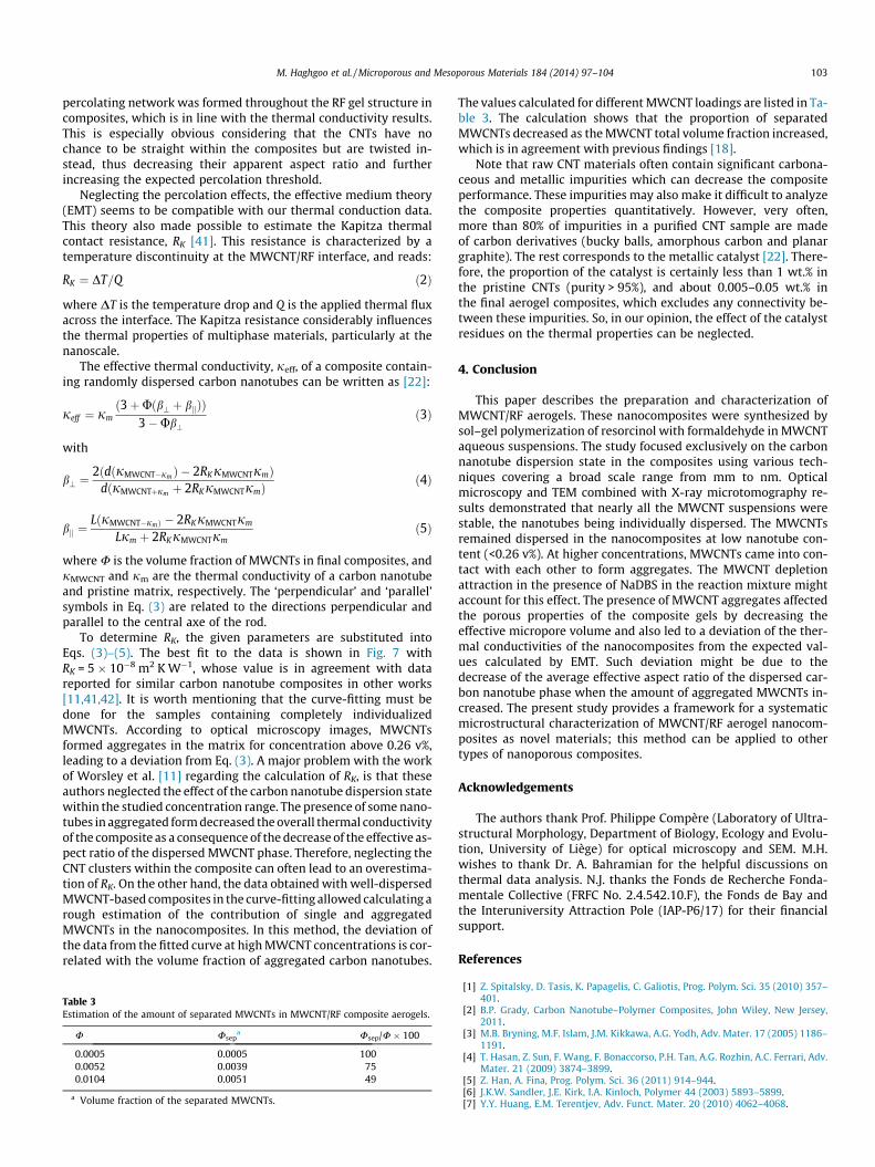
where DT is the temperature drop and Q is the applied thermal fluxacross the interface. The Kapitza resistance considerably influencesthe thermal properties of multiphase materials, particularly at thenanoscale.
The effective thermal conductivity, jeff, of a composite contain-ing randomly dispersed carbon nanotubes can be written as [22]:
jeff ¼ jmð3þUðb? þ bjjÞÞ
3�Ub?ð3Þ
with
b? ¼2ðdðjMWCNT�jm Þ � 2RKjMWCNTjmÞ
dðjMWCNTþjm þ 2RKjMWCNTjmÞð4Þ
bjj ¼LðjMWCNT�jmÞ � 2RKjMWCNTjm
Ljm þ 2RKjMWCNTjmð5Þ
where U is the volume fraction of MWCNTs in final composites, andjMWCNT and jm are the thermal conductivity of a carbon nanotubeand pristine matrix, respectively. The ‘perpendicular’ and ‘parallel’symbols in Eq. (3) are related to the directions perpendicular andparallel to the central axe of the rod.
To determine RK, the given parameters are substituted intoEqs. (3)–(5). The best fit to the data is shown in Fig. 7 withRK = 5 � 10�8 m2 K W�1, whose value is in agreement with datareported for similar carbon nanotube composites in other works[11,41,42]. It is worth mentioning that the curve-fitting must bedone for the samples containing completely individualizedMWCNTs. According to optical microscopy images, MWCNTsformed aggregates in the matrix for concentration above 0.26 v%,leading to a deviation from Eq. (3). A major problem with the workof Worsley et al. [11] regarding the calculation of RK, is that theseauthors neglected the effect of the carbon nanotube dispersion statewithin the studied concentration range. The presence of some nano-tubes in aggregated form decreased the overall thermal conductivityof the composite as a consequence of the decrease of the effective as-pect ratio of the dispersed MWCNT phase. Therefore, neglecting theCNT clusters within the composite can often lead to an overestima-tion of RK. On the other hand, the data obtained with well-dispersedMWCNT-based composites in the curve-fitting allowed calculating arough estimation of the contribution of single and aggregatedMWCNTs in the nanocomposites. In this method, the deviation ofthe data from the fitted curve at high MWCNT concentrations is cor-related with the volume fraction of aggregated carbon nanotubes.
Table 3Estimation of the amount of separated MWCNTs in MWCNT/RF composite aerogels.
U Usepa Usep/U � 100
0.0005 0.0005 1000.0052 0.0039 750.0104 0.0051 49
a Volume fraction of the separated MWCNTs.
The values calculated for different MWCNT loadings are listed in Ta-ble 3. The calculation shows that the proportion of separatedMWCNTs decreased as the MWCNT total volume fraction increased,which is in agreement with previous findings [18].
Note that raw CNT materials often contain significant carbona-ceous and metallic impurities which can decrease the compositeperformance. These impurities may also make it difficult to analyzethe composite properties quantitatively. However, very often,more than 80% of impurities in a purified CNT sample are madeof carbon derivatives (bucky balls, amorphous carbon and planargraphite). The rest corresponds to the metallic catalyst [22]. There-fore, the proportion of the catalyst is certainly less than 1 wt.% inthe pristine CNTs (purity > 95%), and about 0.005–0.05 wt.% inthe final aerogel composites, which excludes any connectivity be-tween these impurities. So, in our opinion, the effect of the catalystresidues on the thermal properties can be neglected.
4. Conclusion
This paper describes the preparation and characterization ofMWCNT/RF aerogels. These nanocomposites were synthesized bysol–gel polymerization of resorcinol with formaldehyde in MWCNTaqueous suspensions. The study focused exclusively on the carbonnanotube dispersion state in the composites using various tech-niques covering a broad scale range from mm to nm. Opticalmicroscopy and TEM combined with X-ray microtomography re-sults demonstrated that nearly all the MWCNT suspensions werestable, the nanotubes being individually dispersed. The MWCNTsremained dispersed in the nanocomposites at low nanotube con-tent (<0.26 v%). At higher concentrations, MWCNTs came into con-tact with each other to form aggregates. The MWCNT depletionattraction in the presence of NaDBS in the reaction mixture mightaccount for this effect. The presence of MWCNT aggregates affectedthe porous properties of the composite gels by decreasing theeffective micropore volume and also led to a deviation of the ther-mal conductivities of the nanocomposites from the expected val-ues calculated by EMT. Such deviation might be due to thedecrease of the average effective aspect ratio of the dispersed car-bon nanotube phase when the amount of aggregated MWCNTs in-creased. The present study provides a framework for a systematicmicrostructural characterization of MWCNT/RF aerogel nanocom-posites as novel materials; this method can be applied to othertypes of nanoporous composites.
Acknowledgements
The authors thank Prof. Philippe Compère (Laboratory of Ultra-structural Morphology, Department of Biology, Ecology and Evolu-tion, University of Liège) for optical microscopy and SEM. M.H.wishes to thank Dr. A. Bahramian for the helpful discussions onthermal data analysis. N.J. thanks the Fonds de Recherche Fonda-mentale Collective (FRFC No. 2.4.542.10.F), the Fonds de Bay andthe Interuniversity Attraction Pole (IAP-P6/17) for their financialsupport.
References
[1] Z. Spitalsky, D. Tasis, K. Papagelis, C. Galiotis, Prog. Polym. Sci. 35 (2010) 357–401.
[2] B.P. Grady, Carbon Nanotube–Polymer Composites, John Wiley, New Jersey,2011.
[3] M.B. Bryning, M.F. Islam, J.M. Kikkawa, A.G. Yodh, Adv. Mater. 17 (2005) 1186–1191.
[4] T. Hasan, Z. Sun, F. Wang, F. Bonaccorso, P.H. Tan, A.G. Rozhin, A.C. Ferrari, Adv.Mater. 21 (2009) 3874–3899.
[5] Z. Han, A. Fina, Prog. Polym. Sci. 36 (2011) 914–944.[6] J.K.W. Sandler, J.E. Kirk, I.A. Kinloch, Polymer 44 (2003) 5893–5899.[7] Y.Y. Huang, E.M. Terentjev, Adv. Funct. Mater. 20 (2010) 4062–4068.

104 M. Haghgoo et al. / Microporous and Mesoporous Materials 184 (2014) 97–104
[8] M.A. Worsley, P.J. Pauzauskie, S.O. Kucheyev, J.M. Zaug, A.V. Hamza, J.H.Satcher, T.F. Baumann, Acta Mater. 57 (2009) 5131–5136.
[9] T. Bordjiba, M. Mohamedi, J. Solid State Electrochem. 15 (4) (2011) 765–771.[10] M.A. Worsley, J.H. Satcher, T.F. Baumann, Langmuir 24 (2008) 9763–9766.[11] M.A. Worsley, J.H. Satcher, T.F. Baumann, J. Appl. Phys. 105 (084316) (2009) 1–
5.[12] R.W. Pekala, J. Mater. Sci. 24 (1989) 3221–3227.[13] S. Bruck, L. Ratke, J. Sol-Gel Sci. Technol. 26 (2003) 663–666.[14] M. Wiener, G. Reichenauer, S. Braxmeier, F. Hemberger, H.-P. Ebert, Int. J.
Thermophys. 30 (2009) 1372–1385.[15] S.J. Kim, S.W. Hwang, S.H. Hyun, J. Mater. Sci. 40 (2005) 725–731.[16] W. Howard, Curr. Opin. Colloid Interface Sci. 14 (2009) 364–371.[17] J. Yu, N. Grossiord, C.E. Koning, J. Loos, Carbon 45 (2007) 618–623.[18] L. Jiang, L. Gao, J. Sun, J. Colloid Interface Sci. 26 (2010) 18874–18883.[19] N.G. Sahoo, S. Rana, J.W. Cho, L. Li, S.H. Chan, Prog. Polym. Sci. 35 (2010) 837–
867.[20] M. Haghgoo, E. Plougonven, A.A. Yousefi, J.-P. Pirard, A. Léonard, N. Job, Carbon
50 (2012) 1703–1706.[21] J. Hilding, E.A. Grulke, Z.G. Zhang, F. Lockwood, J. Dispersion Sci. Technol. 24
(2003) 1–41.[22] M.B. Bryning, Carbon Nanotube Networks in Epoxy Composites and Aerogels,
Ph.D. Thesis, University of Pennsylvania, 2007.[23] A.M. Thayer, Chem. Eng. News 85 (46) (2007) 29–35.[24] J.-P. Pirard, Chem. Eng. News 86 (12) (2008) 5.[25] N. Job, F. Sabatier, J.-P. Pirard, M. Crine, A. Leonard, Carbon 44 (2006) 2534–
2542.
[26] E. Solórzano, J.A. Reglero, M.A. Rodríguez-Pérez, D. Lehmhus, M. Wichmann,J.A. de Saja, Int. J. Heat Mass Transfer 51 (2008) 6259–6267.
[27] M.D. Clark, S. Subramanian, R. Krishnamoorti, J. Colloid Interface Sci. 354(2011) 144–151.
[28] M.S. Strano, M.K. Miller, M.J. Allen, V.C. Moore, M.J. O’Connell, C. Kittrell, R.H.Hauge, R.E. Smalley, J. Nano Sci. Nano Techol. 3 (2003) 81–85.
[29] M. Haghgoo, A.A. Yousefi, M.J. Zohuriaan-Mehr, Iran. Polym. J. 21 (2012) 211–219.
[30] L. Jiang, L. Gao, J. Sun, J. Colloid Interface Sci. 260 (2003) 89–94.[31] B. Vigolo, A. Pénicaud, C. Coulon, C. Sauder, R. Pailler, C. Journet, P. Bernier,
Science 290 (2000) 1331–1334.[32] N. Job, R. Pirard, C. Alié, J.-P. Pirard, Part. Part. Sys. Char. 23 (2006) 72–81.[33] C. Lin, J.A. Ritter, Carbon 35 (1997) 1271–1278.[34] N. Job, R. Pirard, J. Marien, J.-P. Pirard, Carbon 42 (2004) 619–628.[35] N. Job, A. Théry, R. Pirard, J. Marien, L. Kocon, J.-N. Rouzaud, F. Béguin, J.-P.
Pirard, Carbon 43 (2005) 2481–2494.[36] T. Bordjiba, M. Mohamedi, J. Power Sources 172 (2007) 991–998.[37] A. Celzard, C. Deleuze, M. Dufort, G. Furdin, J.F. Marêché, E. McRae, Phys. Rev. B
53 (1996) 6209–6214.[38] A. Celzard, J.F. Marêché, F. Payot, G. Furdin, Carbon 40 (2002) 2801–2815.[39] A. Celzard, V. Fierro, A. Pizzi, Cellulose 15 (2008) 803–814.[40] A. Celzard, V. Fierro, R. Kerekes, Cellulose 16 (2009) 983–987.[41] C.-W. Nan, G. Liu, Y. Lin, M. Li, Appl. Phys. Lett. 85 (2004) 3549–3551.[42] M.B. Bryning, D.E. Milkie, M.F. Islam, J.M. Kikkawa, A.G. Yodh, Appl. Phys. Lett.
87 (2005) 161909–161911.