
Rainbow Bridge NM: Administrative History - National Park ...

41.8-nm Xe8+ laser driven in a plasma waveguide
A. Butler, A. J. Gonsalves, C. M. McKenna, D. J. Spence, and S. M. Hooker*Department of Physics, University of Oxford, Clarendon Laboratory, Parks Road, Oxford OX1 3PU, United Kingdom
S. Sebban,† T. Mocek, and I. BetttaibiLaboratoire d’Optique Appliquée, ENSTA/Ecole Polytechnique, CNRS UMR 7639, F-91761 Palaiseau cedex, France
B. Cros‡
LPGP, UMR 8578, CNRS, Université Paris XI, Bâtiment 210, 91405 Orsay, France(Received 19 April 2004; published 30 August 2004)
An experimental demonstration of an optical field ionization short-wavelength laser driven in a gas-filledcapillary-discharge waveguide is described in detail. Guiding of high-intensity laser pulses has previously beendemonstrated with this type of waveguide for capillary discharges in hydrogen. For the present experimentsxenon gas was mixed with the hydrogen, and strong lasing on the 4d95d-4d95p transition in Xe8+ at 41.8 nmwas observed. Under optimum conditions the short-wavelength laser output achieved with the waveguide wasfound to be greater than that from a Xe gas cell. Measurements of the transmission of the pump laser pulsesthrough the waveguide show that the short-wavelength laser signal was greatest under conditions for which thepump laser pulses were well guided. Simulations of the propagation of the pump laser radiation are presentedfor a range of initial plasma conditions, and these indicate that the laser-plasma interaction length achieved wasgreatly increased compared to that which can be achieved in a gas cell.
DOI: 10.1103/PhysRevA.70.023821 PACS number(s): 42.55.Vc, 52.38.Hb
I. INTRODUCTION
In order to create a population inversion on an extreme-ultraviolet (xuv) or soft-x-ray laser transition, a large pumppower density must be supplied to overcome the high rate ofspontaneous decay of the upper laser level. Ever since thefirst demonstrations[1,2] of lasing at short wavelengths, con-siderable effort has been devoted to reducing the size andincreasing the repetition rate of the visible pump lasers em-ployed. Recently progress towards these goals has beenmade by using picosecond or femtosecond pump laser pulsesof only moderate energy[3–6]. Short-pulse lasers of thistype are compact and able to operate at high repetition rates,making them attractive pump sources for short-wavelengthlasers. An alternative technique, in which fast electrical dis-charges are used to provide the pump power, has been suc-cessfully employed[7] to pump xuv lasers operating at46 nm or longer, but it has proved difficult to scale to shorterwavelengths.
Traveling-wave excitation is often necessary when drivingshort-wavelength lasers owing to the brief duration of thegain. For this geometry the pump laser energy required isminimized by employing longitudinal pumping. However,with this configuration diffraction and refraction of the pumpbeam limit the gain length to only a few millimeters, and asa consequence the small-signal gain coefficient must be veryhigh if lasing is to be achieved. Furthemore, the energy ex-traction and transverse coherence of the short-wavelength
beam are likely to be poor. A direct way to increase theinteraction length would be to employ a larger focal spot, butthis would greatly increase the pump laser pulse energy re-quired. A more favorable approach is to guide the pump laserpulse over long lengths.
Several techniques for guiding high-intensity laser radia-tion have been investigated, including guiding in hollow cap-illaries [8,9], relativistic channeling[10], and several typesof plasma waveguide[11–15]. However, few of these havebeen used to increase the gain length of short-wavelengthlasers. Plasma channels formed by discharge or laser ablationof a LiF capillary have been used to demonstrate[16] recom-bination lasing on then=2→1 transition at 13.5 nm in Li2+.In that work lasing was achieved with 248 nm pump radia-tion for 5-mm-long laser-ablated capillaries and with1053 nm pumping for 14-mm-long discharge-ablated capil-laries. Janulewiczet al. have investigated[17] collisionallyexcited short-wavelength lasers driven within a plasma chan-nel formed by a Z-pinch discharge. Those authors employed1 ps pump pulses from a Nd:glass laser to achieve transientgain on the 3p-3s transition at 60.8 nm in S6+. However, inthat work the spot radius of the pump laser was very large,approximately 170mm, so that the capillary lengths30 mmdwas significantly less than the Rayleigh range of the pumpbeam. While these early results show the promise of drivingshort-wavelength lasers within a plasma channel, evidencefor generation of gain over the full length of the waveguidehas not yet been presented.
In this paper we present in detail the results of the firstexperimental demonstration of a short-wavelength laserdriven within a gas-filled capillary-discharge waveguide.This is also the first time that a collisionally excited opticalfield ionization laser has been driven in any waveguide. The
*Electronic address: [email protected]†Electronic address: [email protected]‡Electronic address: [email protected]
PHYSICAL REVIEW A 70, 023821(2004)
1050-2947/2004/70(2)/023821(10)/$22.50 ©2004 The American Physical Society70 023821-1

results of this experiment have previously been described[18] in brief, but this present report contains additional ex-perimental data, results of numerical simulations, and furtherdiscussion.
The paper is organized as follows. In Secs. II and III webriefly describe the gas-filled capillary-discharge waveguideand the mechanisms by which it operates, and outline theshort-wavelength laser scheme investigated in the present pa-per. In Sec. IV the experimental layout and methods em-ployed are described in detail, the results being described inSec. V. Numerical simulations of the propagation of thepump laser pulse through the waveguide, under the condi-tions found experimentally to optimize the Xe8+ laser signal,are presented in Sec. VI. Finally the results are discussed inSec. VII and conclusions drawn in Sec. VIII.
II. GAS-FILLED CAPILLARY-DISCHARGE WAVEGUIDE
The present work utilizes a gas-filled capillary-dischargewaveguide[19]. In this type of waveguide an electrical dis-charge is struck along the inside of a gas-filled capillary toform a plasma waveguide. Magnetohydrodynamic(MHD)simulations[20] by Bobrovaet al. showed that capillary dis-charges in H2 form a fully ionized plasma channel with adensity that increases approximately quadratically with ra-dial distance from the axis. The channel is formed by radialheat conduction to the capillary walls, which causes theplasma temperature to be greatest, and hence the density tobe lowest, near the capillary axis.
In an ideal plasma waveguide the plasma has a parabolicprofile of the formNesrd=Nes0d+DNesr / rchd2, whereNesrd isthe electron density at a distancer from the capillary axisandDNe is the increase in electron density atr =rch from theaxial valueNes0d. An intense laser pulse passing through aplasma experiences a refractive index which is dominated bythe contribution of free electrons in the plasma and is givenby n=Î1−Nee
2/ smee0v2d, wherev is the angular frequencyof the laser radiation and relativistic effects have been ne-glected. It follows that in a parabolic plasma channel therefractive index is peaked on axis and acts to counter diffrac-tion and ionization-induced defocusing of a laser pulse. If nofurther ionization of the plasma occurs and ponderomotiveand relativistic effects are negligible, a Gaussian beam willpropagate[21] along a parabolic channel with a constant spotradiusWM, providedWM =frch
2 / spreDNedg1/4, wherere is theclassical electron radius. If the spot radius is not matched toWM, then the laser spot radius oscillates as the pulse travelsalong the capillary. This mismatch may be characterized bythe parameterN=WM /Wi. In this case the spot radius variesbetween the spot radius at injection into the capillarysWidandN2Wi =WM
2 /Wi, with a length period given byp2WM2 /l
=pZRM, whereZRM is the Rayleigh range corresponding to alaser spot of spot radiusWM. This intensity oscillation willnot be particularly severe for a small spot radius mismatch.
Guiding high-intensity laser pulses
In earlier work we demonstrated[22,23] low-loss guidingof laser pulses with a peak input intensity of up to 1.2
31017 W cm−2, over lengths of up to 50 mm throughH2-filled capillary-discharge waveguides.
In order to demonstrate short-wavelength lasing in awaveguide of this type, the H2 gas fill must be doped withthe lasant gas. Of course, if the concentration of the lasantgas is too high, the optical field ionization—which is re-quired to generate and pump the lasant ion—will contribute ahigh electron density near the axis, destroying the plasmachannel and preventing a long interaction length from beingachieved.
III. SHORT-WAVELENGTH LASER SCHEME
For pump laser intensities of order 1016 W cm−2 the elec-tric field of the radiation is comparable to the intra-atomicfield experienced by bound electrons in atoms and ions. As aconsequence the bound electrons are rapidly ionized owingto gross distortion of the intra-atomic potential, a processknown as optical field ionization(OFI). The rate of OFI ex-hibits a thresholdlike behavior with the laser intensity, thethreshold intensity corresponding to that which just removesthe barrier formed by the sum of the intra-atomic and laserpotentials[24]. The threshold nature of OFI makes it an at-tractive mechanism for generating plasmas suitable as gainmedia for short-wavelength lasers since the ion stage gener-ated may be controlled by adjusting the laser intensity. Fur-ther, the energy of the electrons after the passage of the laserpulse can be controlled through the polarization of the laserradiation: linear polarization generates relatively cold elec-trons, suitable for pumping recombination lasers; circular po-larization produces hot electrons which can pump populationinversions by electron collisions[25].
For this proof-of-principle experiment it was decided toinvestigate the collisionally excited OFI laser scheme in Xe8+
proposed[26], and later demonstrated[5], by Lemoff et al.In the past few years Sebbanet al. have characterized theoperation of this laser in detail and reported saturation of thelaser transition[27–29]. In both these previous experimentsfemtosecond laser pulses were focused into a differentiallypumped gas cell containing pure Xe, and the gain lengthachieved was less than 8.5 mm, owing to diffractive and re-fractive defocusing of the pump beam.
The Xe8+ laser operates as follows. Gaseous Xe is ionizedto Xe8+ by OFI with high-intensity, circularly polarized ra-diation from a Ti:sapphire laser. The threshold pump laserintensity for forming Xe8+ is approximately 531016 W cm−2. Achieving the correct laser intensity on tar-get is vital to forming the required ion stage for the lasersystem. For example, the threshold intensity to overionize toform Xe9+ is 231017 W cm−2, only about 4 times the inten-sity necessary to form Xe8+. The use of circularly polarizedradiation ensures that the field-ionized electrons retain highenergies after passage of the pump laser pulse, thereby al-lowing rapid collisional excitation of the upper laser level.
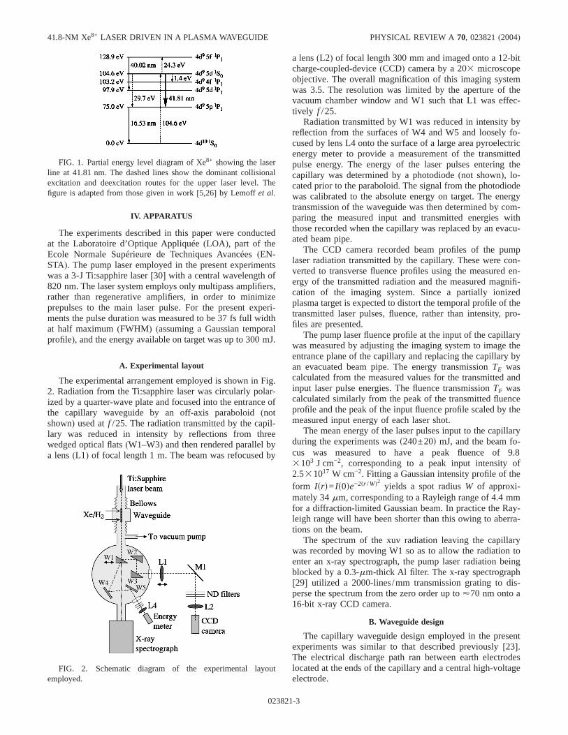
A simplified diagram of the atomic structure of Xe8+ isshown in Fig. 1. This shows the dominant collisional pump-ing and deexcitation routes, and some important electromag-netic transitions. The laser transition is 4d95d 1S0-4d95p 1P1at 41.81 nm.
BUTLER et al. PHYSICAL REVIEW A 70, 023821(2004)
023821-2
IV. APPARATUS
The experiments described in this paper were conductedat the Laboratoire d’Optique Appliquée(LOA), part of theEcole Normale Supérieure de Techniques Avancées(EN-STA). The pump laser employed in the present experimentswas a 3-J Ti:sapphire laser[30] with a central wavelength of820 nm. The laser system employs only multipass amplifiers,rather than regenerative amplifiers, in order to minimizeprepulses to the main laser pulse. For the present experi-ments the pulse duration was measured to be 37 fs full widthat half maximum(FWHM) (assuming a Gaussian temporalprofile), and the energy available on target was up to 300 mJ.
A. Experimental layout
The experimental arrangement employed is shown in Fig.2. Radiation from the Ti:sapphire laser was circularly polar-ized by a quarter-wave plate and focused into the entrance ofthe capillary waveguide by an off-axis paraboloid(notshown) used atf /25. The radiation transmitted by the capil-lary was reduced in intensity by reflections from threewedged optical flats(W1–W3) and then rendered parallel bya lens(L1) of focal length 1 m. The beam was refocused by
a lens(L2) of focal length 300 mm and imaged onto a 12-bitcharge-coupled-device(CCD) camera by a 203 microscopeobjective. The overall magnification of this imaging systemwas 3.5. The resolution was limited by the aperture of thevacuum chamber window and W1 such that L1 was effec-tively f /25.
Radiation transmitted by W1 was reduced in intensity byreflection from the surfaces of W4 and W5 and loosely fo-cused by lens L4 onto the surface of a large area pyroelectricenergy meter to provide a measurement of the transmittedpulse energy. The energy of the laser pulses entering thecapillary was determined by a photodiode(not shown), lo-cated prior to the paraboloid. The signal from the photodiodewas calibrated to the absolute energy on target. The energytransmission of the waveguide was then determined by com-paring the measured input and transmitted energies withthose recorded when the capillary was replaced by an evacu-ated beam pipe.
The CCD camera recorded beam profiles of the pumplaser radiation transmitted by the capillary. These were con-verted to transverse fluence profiles using the measured en-ergy of the transmitted radiation and the measured magnifi-cation of the imaging system. Since a partially ionizedplasma target is expected to distort the temporal profile of thetransmitted laser pulses, fluence, rather than intensity, pro-files are presented.
The pump laser fluence profile at the input of the capillarywas measured by adjusting the imaging system to image theentrance plane of the capillary and replacing the capillary byan evacuated beam pipe. The energy transmissionTE wascalculated from the measured values for the transmitted andinput laser pulse energies. The fluence transmissionTF wascalculated similarly from the peak of the transmitted fluenceprofile and the peak of the input fluence profile scaled by themeasured input energy of each laser shot.
The mean energy of the laser pulses input to the capillaryduring the experiments wass240±20d mJ, and the beam fo-cus was measured to have a peak fluence of 9.83103 J cm−2, corresponding to a peak input intensity of2.531017 W cm−2. Fitting a Gaussian intensity profile of theform Isrd= Is0de−2sr /Wd2 yields a spot radiusW of approxi-mately 34mm, corresponding to a Rayleigh range of 4.4 mmfor a diffraction-limited Gaussian beam. In practice the Ray-leigh range will have been shorter than this owing to aberra-tions on the beam.
The spectrum of the xuv radiation leaving the capillarywas recorded by moving W1 so as to allow the radiation toenter an x-ray spectrograph, the pump laser radiation beingblocked by a 0.3-mm-thick Al filter. The x-ray spectrograph[29] utilized a 2000-lines/mm transmission grating to dis-perse the spectrum from the zero order up to<70 nm onto a16-bit x-ray CCD camera.
B. Waveguide design
The capillary waveguide design employed in the presentexperiments was similar to that described previously[23].The electrical discharge path ran between earth electrodeslocated at the ends of the capillary and a central high-voltageelectrode.
FIG. 1. Partial energy level diagram of Xe8+ showing the laserline at 41.81 nm. The dashed lines show the dominant collisionalexcitation and deexcitation routes for the upper laser level. Thefigure is adapted from those given in work[5,26] by Lemoff et al.
FIG. 2. Schematic diagram of the experimental layoutemployed.
41.8-NM Xe8+ LASER DRIVEN IN A PLASMA WAVEGUIDE PHYSICAL REVIEW A 70, 023821(2004)
023821-3
The electric circuit which generated the discharge pulsewas similar to that described[22] previously. A 4.5-nF stor-age capacitor was charged to 20–30 kV and switched acrossthe capillary using a thyratron switch. The circuit inductancewas increased from that employed in previous work[23] toslow the discharge and reduce the peak current. The currentpulse produced was measured with a Rogowski coil and wasfound to be a damped, approximately sinusoidal profile, witha quarter period of 500 ns and a peak value of 105 A per arm(temporal behavior as shown in Fig. 5). The time at whichthe laser pulse was injected into the capillary was determinedby detecting with a photodiode the radiation leaking througha mirror located a known distance before the capillary. Theinjection time delayt is defined from the initiation of themeasured discharge current pulse.
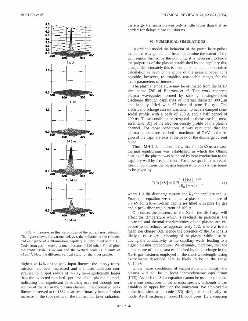
Alumina sAl2O3d capillaries of length 30 mm and internaldiameter 210mm, of the design shown in Fig. 3, were em-ployed. In order to introduce gas into the capillary, slots oflength 0.8 mm and approximately 75mm wide were ma-chined with their centers located 4.4 mm from the ends ofthe capillary. To increase the gas flow rate, four slots weredrilled, with azimuthal symmetry, near both ends of the cap-illary. Four central, 0.6-mm-long slots, were also machinedwith azimuthal symmetry, to allow the discharge current toflow.
The capillary and electrodes were mounted in a holder[23] which was connected to the surrounding vacuum systemby flexible bellows. The entire system was mounted on afive-axis optical stage to enable alignment of the axis of thecapillary to the input laser beam.
Premade mixtures of Xe and H2 gas were flowed into thecapillary, the flow rate of the gas mix being measured by agap flow meter calibrated in separate experiments against thepressure at the center of the capillary.
In order to facilitate a comparison with previous demon-strations of lasing on this transition, xuv lasing in a Xe-filledgas cell similar to that used by Sebbanet al. was also inves-tigated. For those experiments the waveguide was removedand the cell positioned so that the vacuum focus of the pumplaser was located 2.5 mm after the entrance pinhole. In thisconfiguration the pump laser radiation entered and exited thegas cell through two pinholes of 200–500mm diameter,separated by 4 mm. These values for the cell length and laserfocal position are very similar to those found[29] to be op-timum by Sebbanet al.
V. RESULTS
A. Short-wavelength lasing
Lasing on the 41.8-nm transition of Xe8+ was investigatedfor a wide range of Xe/H mixtures, total gas pressure, and
pump laser injection delayt. Lasing was first observed usinga 1:7 Xe:H atom ratio gas mixture, was strongest for a mix-ture of 1:3, and was also observed for a mixture of 1:1.3. Forthe best gas mixture, the optimum total gas pressure wasfound to be 120 mbar.
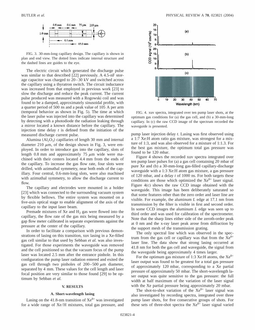
Figure 4 shows the recorded xuv spectra integrated overten pump laser pulses for(a) a gas cell containing 20 mbar ofpure Xe and(b) a 30-mm-long gas-filled capillary-dischargewaveguide with a 1:3 Xe:H atom gas mixture, a gas pressureof 120 mbar, and a delayt of 1000 ns. For both targets theseconditions are those which optimized the Xe8+ laser signal.Figure 4(c) shows the raw CCD image obtained with thewaveguide. This image has been deliberately saturated sothat some features other than the zero order and laser line arevisible. For example, the aluminumL edge at 17.1 nm fromtransmission by the filter is visible in first and second order.In some CCD images the aluminumL edge was seen up tothird order and was used for calibration of the spectrometer.Note that the sharp lines either side of the zeroth-order peakat 0 nm and the x-ray laser peak arose from diffraction bythe support mesh of the transmission grating.
The only spectral line which was observed in the spec-trum from the gas cell or capillary was that from the Xe8+
laser line. The data show that strong lasing occurred at41.8 nm for both the gas cell and waveguide, the signal fromthe waveguide being approximately 4 times larger.
For the optimum gas mixture of 1:3 Xe:H atoms, the Xe8+
laser output was found to be greatest for a total gas pressureof approximately 120 mbar, corresponding to a Xe partialpressure of approximately 50 mbar. The short-wavelength la-ser output was quite sensitive to the gas pressure: the fullwidth at half maximum of the variation of the laser signalwith the Xe partial pressure being approximately 20 mbar.
The shot-to-shot variation of the Xe8+ laser signal wasalso investigated by recording spectra, integrated over threepump laser shots, for five consecutive groups of shots. Forthese sets of three-shot spectra the Xe8+ laser signal varied
FIG. 3. 30-mm-long capillary design. The capillary is shown inplan and end view. The dotted lines indicate internal structure andthe dashed lines are guides to the eye.
FIG. 4. xuv spectra, integrated over ten pump laser shots, at theoptimum gas conditions for(a) the gas cell, and(b) a 30-mm-longcapillary. In (c) the raw CCD image of the spectrum recorded thewaveguide is presented.
BUTLER et al. PHYSICAL REVIEW A 70, 023821(2004)
023821-4
by only 4%, indicating that short-wavelength lasing occurredon each pump laser shot.
B. Guiding
In order to understand the correlation between the experi-mental conditions which optimized the output of the Xe8+
laser and the behavior of the plasma channel as a waveguide,the temporal behavior of the pump laser pulse transmissionwas recorded for Xe/H mixtures and pure H2 gas fills.
Figure 5 shows, for the optimum Xe8+ laser gas mixtureand pressure, the dependence of the peak transmitted pumplaser fluenceTF on the injection delayt of the pump laserpulses. The quantityTF is plotted here, rather than the pulseenergy transmissionTE, since it is more closely related to theOFI rate. It is seen that the fluence transmission was approxi-mately 0.2% for laser pulses injected before the initiation ofthe discharge current.TF increased slowly to around 2% fordelays of approximately 900 ns. ThereafterTF increased rap-idly by a factor of approximately 6 and peaked at 13% fordelays close to 1000 ns. At later timesTF fell slowly. Thepulse energy transmissionsTEd behaved similarly, reaching apeak of approximately 55% for delays close to 1000 ns. Therapid rise inTF was proportionally greater than that inTEbecause there was an associated reduction in the spot radiusof the guided pump laser pulse.
Figure 5 also shows, again for the optimum gas mixture,the variation of the Xe8+ laser signal with the delayt betweenthe onset of the discharge current and the injection of thepump laser pulse. It is seen that the Xe8+ laser signal wasvery sensitive to the delay at which the pump laser pulse wasinjected. For all the experiments performed, lasing was onlyobserved for a range of delays approximately 200 ns wide,centered at a delay of approximately 1000 ns. This correlateswell with the delayt for which the highest values ofTF wereobserved.
Figure 6 shows the measured pulse transmissionTE andTF for a 1:3 Xe:H atom mixture and various total gas pres-sures. It is seen that for all the Xe-H mixturesTE and TFincreased relatively slowly during the first part of the dis-
charge pulse, followed by a rapid increase at a delay close to900 ns. The highestTE values of around 55% were obtainedfor delayst of approximately 1000 ns. ThereafterTE fell to20% for delayst of around 2000 ns.TF is seen to behavesimilarly to TE, but as in Fig. 5 the increase inTF wassharper than that ofTE due to the associated spatial con-straint of the laser pulse for delayst close to 1000 ns. Care-ful inspection shows that the best guiding occurred for a totalpressure of 120 mbar, equal to the total pressure that opti-mized the short-wavelength laser output.
The rise inTE and TF observed for Xe-H mixtures wasmuch slower than previously found for capillary dischargesin pure hydrogen[23]. Measurements with the present appa-ratus confirmed this: for discharges through capillaries filledwith pure hydrogen at an initial pressure of 110 mbarTE wasfound to reach 70% for delays of only 100 ns.
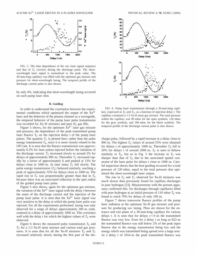
Figure 7 shows transverse fluence profiles of the pumplaser radiation at the optimum Xe-H gas mixture and pres-sure for producing xuv lasing. Plots are shown for the en-trance and exit plane of a 30-mm-long capillary for variousdelays t. It is seen that for delayst,0 ns the transmittedfluence was very low. Even for a delayt as long as 823 nsthe transmitted fluence was still below 2% of the peak inputfluence due to the energy transmission being low and theenergy which was transmitted being spread over a large area.At a delay t of 1014 ns the peak transmitted fluence was
FIG. 5. The time dependence of the xuv laser signal(squares)and that of TF (circles) during the discharge pulse. The short-wavelength laser signal is normalized to the peak value. The30-mm-long capillary was filled with the optimum gas mixture andpressure for short-wavelength lasing. The temporal profile of thedischarge current pulse is also shown.
FIG. 6. Pump laser transmission through a 30-mm-long capil-lary, expressed asTE andTF, as a function of injection delayt. Thecapillary contained a 1:3 Xe:H atom gas mixture. The total pressurewithin the capillary was 90 mbar for the open symbols, 120 mbarfor the gray symbols, and 180 mbar for the black symbols. Thetemporal profile of the discharge current pulse is also shown.
41.8-NM Xe8+ LASER DRIVEN IN A PLASMA WAVEGUIDE PHYSICAL REVIEW A 70, 023821(2004)
023821-5
highest at 14% of the peak input fluence: the energy trans-mission had been increased and the laser radiation con-strained to a spot radius of<70 mm—significantly largerthan the expected matched spot size of the plasma channel,indicating that significant defocusing occurred through ion-ization of the Xe in the plasma channel. The decreased peakfluence observed att=1384 ns arises primarily from a furtherincrease in the spot radius of the transmitted laser radiation;
the energy transmission was only a little lower than that re-corded for delays close to 1000 ns.
VI. NUMERICAL SIMULATIONS
In order to model the behavior of the pump laser pulsesinside the waveguide, and hence determine the extent of thegain region formed by the pumping, it is necessary to knowthe properties of the plasma established by the capillary dis-charge. Unfortunately this is a complex matter, and a detailedcalculation is beyond the scope of the present paper. It ispossible, however, to establish reasonable ranges for themain parameters of interest.
The plasma temperature may be estimated from the MHDsimulations [20] of Bobrova et al. That work concernsplasma waveguides formed by striking a single-endeddischarge through capillaries of internal diameter 300mmand initially filled with 67 mbar of pure H2 gas. Theelectrical discharge current was taken to have a damped sinu-soidal profile with a peak of 250 A and a half period of200 ns. These conditions correspond to those used in mea-surements[31] of the electron density profile of the plasmachannel. For those conditions it was calculated that theplasma temperature reached a maximum of 7 eV in the re-gion of the capillary axis at the peak of the discharge currentpulse.
Those MHD simulations show that fort*80 ns a quasi-thermal equilibrium was established in which the Ohmicheating of the plasma was balanced by heat conduction to thecapillary wall by free electrons. For these quasithermal equi-librium conditions the plasma temperature on axis was foundto be given by
Ts0d feVg < 5.7S I fkAgR0 fmmgD
2/5
, s1d
whereI is the discharge current andR0 the capillary radius.From this equation we calculate a plasma temperature of5.7 eV for 210-mm-diam capillaries filled with pure H2 gasand a peak discharge current of 105 A.
Of course, the presence of the Xe in the discharge willaffect the temperature which is reached. In particular, theelectrical and thermal conductivities of the plasma are ex-pected to be reduced as approximately 1/Z, whereZ is themean ion charge[32]. Hence the presence of the Xe ions islikely to cause greater heating of the plasma while also re-ducing the conductivity to the capillary walls, leading to ahigher plasma temperature. We estimate, therefore, that thetemperature of the plasma established by the discharge in theXe-H gas mixtures employed in the short-wavelength lasingexperiments described here is likely to be in the range6–12 eV.
Under these conditions of temperature and density theplasma will not be in local thermodynamic equilibrium(LTE). As such the Saha equation cannot be used to calculatethe mean ionization of the plasma species, although it canestablish an upper limit on the ionization. We employed anumerical simulation code[33] designed specifically tomodel Ar-H mixtures in non-LTE conditions. By comparing
FIG. 7. Transverse fluence profiles of the pump laser radiation.The figure shows, for various delayst, the radiation at the entranceand exit plane of a 30-mm-long capillary initially filled with a 1:3Xe:H atom gas mixture at a total pressure of 120 mbar. For all plotsthe spatial scale is inmm and the vertical scale is in units ofkJ cm−2. Note the different vertical scale for the input profile.
BUTLER et al. PHYSICAL REVIEW A 70, 023821(2004)
023821-6
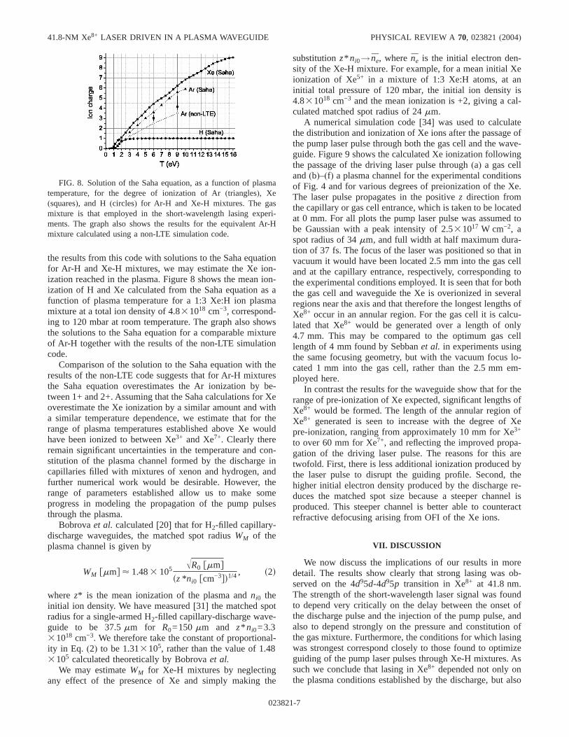
the results from this code with solutions to the Saha equationfor Ar-H and Xe-H mixtures, we may estimate the Xe ion-ization reached in the plasma. Figure 8 shows the mean ion-ization of H and Xe calculated from the Saha equation as afunction of plasma temperature for a 1:3 Xe:H ion plasmamixture at a total ion density of 4.831018 cm−3, correspond-ing to 120 mbar at room temperature. The graph also showsthe solutions to the Saha equation for a comparable mixtureof Ar-H together with the results of the non-LTE simulationcode.
Comparison of the solution to the Saha equation with theresults of the non-LTE code suggests that for Ar-H mixturesthe Saha equation overestimates the Ar ionization by be-tween 1+ and 2+. Assuming that the Saha calculations for Xeoverestimate the Xe ionization by a similar amount and witha similar temperature dependence, we estimate that for therange of plasma temperatures established above Xe wouldhave been ionized to between Xe3+ and Xe7+. Clearly thereremain significant uncertainties in the temperature and con-stitution of the plasma channel formed by the discharge incapillaries filled with mixtures of xenon and hydrogen, andfurther numerical work would be desirable. However, therange of parameters established allow us to make someprogress in modeling the propagation of the pump pulsesthrough the plasma.
Bobrovaet al. calculated[20] that for H2-filled capillary-discharge waveguides, the matched spot radiusWM of theplasma channel is given by
WM fmmg < 1.483 105ÎR0 fmmg
sz*ni0 fcm−3gd1/4, s2d
wherez* is the mean ionization of the plasma andni0 theinitial ion density. We have measured[31] the matched spotradius for a single-armed H2-filled capillary-discharge wave-guide to be 37.5mm for R0=150mm and z* ni0=3.331018 cm−3. We therefore take the constant of proportional-ity in Eq. (2) to be 1.313105, rather than the value of 1.483105 calculated theoretically by Bobrovaet al.
We may estimateWM for Xe-H mixtures by neglectingany effect of the presence of Xe and simply making the
substitutionz* ni0→ n̄e, wheren̄e is the initial electron den-sity of the Xe-H mixture. For example, for a mean initial Xeionization of Xe5+ in a mixture of 1:3 Xe:H atoms, at aninitial total pressure of 120 mbar, the initial ion density is4.831018 cm−3 and the mean ionization is +2, giving a cal-culated matched spot radius of 24mm.
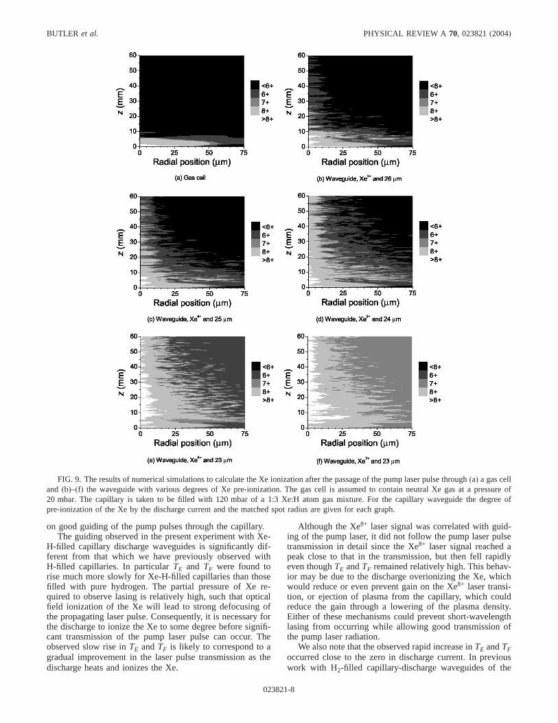
A numerical simulation code[34] was used to calculatethe distribution and ionization of Xe ions after the passage ofthe pump laser pulse through both the gas cell and the wave-guide. Figure 9 shows the calculated Xe ionization followingthe passage of the driving laser pulse through(a) a gas celland(b)–(f) a plasma channel for the experimental conditionsof Fig. 4 and for various degrees of preionization of the Xe.The laser pulse propagates in the positivez direction fromthe capillary or gas cell entrance, which is taken to be locatedat 0 mm. For all plots the pump laser pulse was assumed tobe Gaussian with a peak intensity of 2.531017 W cm−2, aspot radius of 34mm, and full width at half maximum dura-tion of 37 fs. The focus of the laser was positioned so that invacuum it would have been located 2.5 mm into the gas celland at the capillary entrance, respectively, corresponding tothe experimental conditions employed. It is seen that for boththe gas cell and waveguide the Xe is overionized in severalregions near the axis and that therefore the longest lengths ofXe8+ occur in an annular region. For the gas cell it is calcu-lated that Xe8+ would be generated over a length of only4.7 mm. This may be compared to the optimum gas celllength of 4 mm found by Sebbanet al. in experiments usingthe same focusing geometry, but with the vacuum focus lo-cated 1 mm into the gas cell, rather than the 2.5 mm em-ployed here.
In contrast the results for the waveguide show that for therange of pre-ionization of Xe expected, significant lengths ofXe8+ would be formed. The length of the annular region ofXe8+ generated is seen to increase with the degree of Xepre-ionization, ranging from approximately 10 mm for Xe3+
to over 60 mm for Xe7+, and reflecting the improved propa-gation of the driving laser pulse. The reasons for this aretwofold. First, there is less additional ionization produced bythe laser pulse to disrupt the guiding profile. Second, thehigher initial electron density produced by the discharge re-duces the matched spot size because a steeper channel isproduced. This steeper channel is better able to counteractrefractive defocusing arising from OFI of the Xe ions.
VII. DISCUSSION
We now discuss the implications of our results in moredetail. The results show clearly that strong lasing was ob-served on the 4d95d-4d95p transition in Xe8+ at 41.8 nm.The strength of the short-wavelength laser signal was foundto depend very critically on the delay between the onset ofthe discharge pulse and the injection of the pump pulse, andalso to depend strongly on the pressure and constitution ofthe gas mixture. Furthermore, the conditions for which lasingwas strongest correspond closely to those found to optimizeguiding of the pump laser pulses through Xe-H mixtures. Assuch we conclude that lasing in Xe8+ depended not only onthe plasma conditions established by the discharge, but also
FIG. 8. Solution of the Saha equation, as a function of plasmatemperature, for the degree of ionization of Ar(triangles), Xe(squares), and H (circles) for Ar-H and Xe-H mixtures. The gasmixture is that employed in the short-wavelength lasing experi-ments. The graph also shows the results for the equivalent Ar-Hmixture calculated using a non-LTE simulation code.
41.8-NM Xe8+ LASER DRIVEN IN A PLASMA WAVEGUIDE PHYSICAL REVIEW A 70, 023821(2004)
023821-7
on good guiding of the pump pulses through the capillary.The guiding observed in the present experiment with Xe-
H-filled capillary discharge waveguides is significantly dif-ferent from that which we have previously observed withH-filled capillaries. In particularTE and TF were found torise much more slowly for Xe-H-filled capillaries than thosefilled with pure hydrogen. The partial pressure of Xe re-quired to observe lasing is relatively high, such that opticalfield ionization of the Xe will lead to strong defocusing ofthe propagating laser pulse. Consequently, it is necessary forthe discharge to ionize the Xe to some degree before signifi-cant transmission of the pump laser pulse can occur. Theobserved slow rise inTE andTF is likely to correspond to agradual improvement in the laser pulse transmission as thedischarge heats and ionizes the Xe.
Although the Xe8+ laser signal was correlated with guid-ing of the pump laser, it did not follow the pump laser pulsetransmission in detail since the Xe8+ laser signal reached apeak close to that in the transmission, but then fell rapidlyeven thoughTE andTF remained relatively high. This behav-ior may be due to the discharge overionizing the Xe, whichwould reduce or even prevent gain on the Xe8+ laser transi-tion, or ejection of plasma from the capillary, which couldreduce the gain through a lowering of the plasma density.Either of these mechanisms could prevent short-wavelengthlasing from occurring while allowing good transmission ofthe pump laser radiation.
We also note that the observed rapid increase inTE andTFoccurred close to the zero in discharge current. In previouswork with H2-filled capillary-discharge waveguides of the
FIG. 9. The results of numerical simulations to calculate the Xe ionization after the passage of the pump laser pulse through(a) a gas celland (b)–(f) the waveguide with various degrees of Xe pre-ionization. The gas cell is assumed to contain neutral Xe gas at a pressure of20 mbar. The capillary is taken to be filled with 120 mbar of a 1:3 Xe:H atom gas mixture. For the capillary waveguide the degree ofpre-ionization of the Xe by the discharge current and the matched spot radius are given for each graph.
BUTLER et al. PHYSICAL REVIEW A 70, 023821(2004)
023821-8

design employed here,TE was found to decrease slightly fordelays close to a zero in the discharge current[23]. Correla-tions between the transmission of the waveguide, short-wavelength laser output, and zeros in the discharge currentmay be caused by nonuniformities in the plasma near thecentral electrode when the discharge current flows, but thesepoints of detail require further investigation. They do not,however, contradict the main conclusion that good guiding ofthe pump laser pulse was required for lasing in Xe8+ to beobserved.
The data presented in Fig. 7 show that with the optimumXe-H gas mixture for Xe8+ lasing, the spot radius of thetransmitted laser pulse at the delay for best guiding was ap-proximately 70mm, significantly bigger than either that ofthe input pulse or the expected matched spot radius of theplasma channel. At a radius equal to that of the capillarywall, a lowest-order Gaussian beam with a spot radius of70 mm has an intensity equal to 1% of that on axis. As such,guiding of the pump laser pulses may have been affected, tosome extent, by interactions with the capillary wall. How-ever, the strong dependence on the delayt of the energy andspatial profile of the transmitted laser pulses indicates thatthe guiding was dominated by the plasma channel; if the roleof the plasma channel was small compared to that of reflec-tions from the capillary wall, the energy and spatial profile ofthe transmitted pulse would be essentially independent oftonce the discharge had sufficiently ionized the Xe to allowguiding. We note that in the simulations presented here, ra-diation reaching the capillary wall was absorbed and hencereflections from the wall were eliminated. The inclusion ofreflection of pump laser radiation at the capillary wall wouldrefocus energy towards the capillary axis and tend to in-crease the length of Xe8+ produced under otherwise identicalconditions.
Although the simulations show that the length over whichXe8+ is formed is increased by the use of a Xe-H-filledcapillary-discharge waveguide, the kinetics of the short-wavelength laser transition will be different from those in agas cell[19]. In particular the small-signal gain coefficient islikely to be reduced by a combination of reduction of thepopulation inversion owing to increased collisional deexcita-tion of the upper laser level, increased Doppler and Stark
widths of the laser transition due to the higher ion tempera-ture and the increased electron density in the plasma, reducedpumping of the upper laser level since there will be fewer hotOFI electrons following preionization of the Xe by the dis-charge, and possible cooling of the OFI electrons by colli-sions with the relatively cold electrons formed by the dis-charge. A detailed calculation of the kinetics of the Xe8+
laser operating under the conditions found in the waveguideplasma channel is beyond the scope of the present paper.However, the facts that lasing was observed with thecapillary-discharge waveguide and the signal was at least asstrong as that from the gas cell imply that for the presentexperiments the increase in gain length more than compen-sated any decrease in small-signal gain. Further, we note thatthe presence of a dense pool of cold electrons in the plasmawaveguide could significantly enhance the small-signal gaincoefficient of recombination lasers driven within gas-filledcapillary-discharge waveguides[35].
VIII. CONCLUSIONS
In summary, we have presented in detail the results andanalysis of an experiment to demonstrate lasing on an ex-treme ultraviolet transition driven in a gas-filled capillary-discharge waveguide. Analysis shows that lasing wasstrongly correlated with good guiding of the pump pulse, andnumerical simulations indicate that gain is likely to havebeen achieved over a significant fraction of the 30 mmlength of the capillary. The success of this proof-of-principleexperiment suggests that this and other short-wavelength la-sers could be driven within waveguides of this type, leadingto increased energy output and reduced beam divergence.
ACKNOWLEDGMENTS
The authors acknowledge invaluable technical assistancefrom the laser support staff at Laboratoire d’OptiqueAppliquée-ENSTA. A.B., A.J.G., and C.M.Mc.K. are grate-ful to the EPSRC for financial support. T.M. is supported bythe European Commission and S.M.H. by the Royal Society.This work was supported by the European Union via theAccess to Large Scale Facilities Program, Contract No.HPRI-1999-CT-00086.
[1] D. L. Matthewset al., Phys. Rev. Lett.54, 110 (1985).[2] S. Suckewer, C. H. Skinner, D. Kim, E. Valeo, D. Voorhees,
and A. Wouters, Phys. Rev. Lett.57, 1004(1986).[3] V. N. Shlyaptsev, P. V. Nickles, T. Schlegel, M. P. Kalashni-
kov, and A. L. Osterheld, Proc. SPIE2012, 111 (1993).[4] J. Nilsen, B. J. MacGowan, L. B. Da Silva, and J. C. Moreno,
Phys. Rev. A48, 4682(1993).[5] B. E. Lemoff, G. Y. Yin, C. L. Gordon III, C. P. J. Barty, and
S. E. Harris, Phys. Rev. Lett.74, 1574(1995).[6] S. Sebbanet al., Phys. Rev. Lett.89, 253901(2002).[7] J. J. Rocca, V. Shlyaptsev, F. G. Tomasel, O. D. Cortazar, D.
Hartshorn, and J. L. A. Chilla, Phys. Rev. Lett.73, 2192(1994).
[8] S. Jackel, R. Burris, J. Grun, A. Ting, C. Manka, K. Evans, andJ. Kosakowskii, Opt. Lett.20, 1086(1995).
[9] F. Dorchieset al., Phys. Rev. Lett.82, 4655(1999).[10] P. Monot, T. Auguste, P. Gibbon, F. Jakober, G. Mainfray, A.
Dulieu, M. Louis-Jacquet, G. Malka, and J. L. Miquel, Phys.Rev. Lett. 74, 2953(1995).
[11] Y. Ehrlich, C. Cohen, A. Zigler, J. Krall, P. Sprangle, and E.Esarey, Phys. Rev. Lett.77, 4186(1996).
[12] T. Hosokai, M. Kando, H. Dewa, H. Kotaki, S. Kondo, N.Hasegawa, K. Nakajima, and K. Horioka, Opt. Lett.25, 10(2000).
[13] H. M. Milchberg, C. G. Durfee, and T. J. McIlrath, Phys. Rev.Lett. 75, 2494(1995).
41.8-NM Xe8+ LASER DRIVEN IN A PLASMA WAVEGUIDE PHYSICAL REVIEW A 70, 023821(2004)
023821-9

[14] P. Volfbeyn, E. Esarey, and W. P. Leemans, Phys. Plasmas6,2269 (1999).
[15] E. W. Gaul, S. P. Le Blanc, A. R. Rundquist, R. Zgadzaj, H.Langhoff, and M. C. Downer, Appl. Phys. Lett.77, 4112(2000).
[16] D. V. Korobkin, C. H. Nam, S. Suckewer, and A. Goltsov,Phys. Rev. Lett.77, 5206(1996).
[17] K. A. Janulewicz, J. J. Rocca, F. Bortolotto, M. P. Kalachni-kov, V. N. Shlyaptsev, W. Sandner, and P. V. Nickles, Phys.Rev. A 63, 033803(2001).
[18] A. Butler, A. J. Gonsalves, C. M. McKenna, D. J. Spence, S.M. Hooker, S. Sebban, T. Mocek, I. Bettaibi, and B. Cros,Phys. Rev. Lett.91, 205001(2003).
[19] D. J. Spence, A. Butler, and S. M. Hooker, J. Opt. Soc. Am. B20, 138 (2003).
[20] N. A. Bobrova, A. A. Esaulov, J. I. Sakai, P. V. Sasorov, D. J.Spence, A. Butler, S. M. Hooker, and S. V. Bulanov, Phys.Rev. E 65, 016407(2002).
[21] E. Esarey, P. Sprangle, J. Krall, and A. Ting, IEEE J. QuantumElectron. 33, 1879(1997).
[22] D. J. Spence, A. Butler, and S. M. Hooker, J. Phys. B34, 4103(2001).
[23] A. Butler, D. J. Spence, and S. M. Hooker, Phys. Rev. Lett.
89, 185003(2002).[24] S. Augst, D. Strickland, D. D. Meyerhofer, S. L. Chin, and J.
H. Eberly, Phys. Rev. Lett.63, 2212(1989).[25] P. B. Corkum, N. H. Burnett, and F. Brunel, Phys. Rev. Lett.
62, 1259(2004).[26] B. E. Lemoff, C. P. J. Barty, and S. E. Harris, Opt. Lett.19,
569 (1994).[27] S. Sebbanet al., J. Opt. Soc. Am. B20, 195 (2003).[28] T. Moceket al., Appl. Phys. B: Lasers Opt.78, 939 (2004).[29] S. Sebbanet al., Phys. Rev. Lett.86, 3004(2001).[30] M. Pittman, S. Ferre, J. P. Rousseau, L. Notebaert, J. P. Cham-
baret, and G. Cheriaux, Appl. Phys. B: Lasers Opt.74, 529(2002).
[31] D. J. Spence and S. M. Hooker, Phys. Rev. E63, 015401(2001).
[32] L. Spitzer, Jr.,Physics of Fully Ionized Gases(Interscience,New York, 1962), Secs. 5.4 and 5.5.
[33] G. J. Pert, J. Phys. B23, 619 (1990).[34] D. J. Spence and S. M. Hooker, J. Opt. Soc. Am. B17, 1565
(2000).[35] D. J. Spence, A. Butler, and S. M. Hooker, J. Opt. Soc. Am. B
20, 138 (2003).
BUTLER et al. PHYSICAL REVIEW A 70, 023821(2004)
023821-10
Copyright © 2022 FDOKUMEN