Centrifuge modeling of one-step outflow tests for unsaturated ...
16
HAL Id: hal-00305021 https://hal.archives-ouvertes.fr/hal-00305021 Submitted on 5 Oct 2006 HAL is a multi-disciplinary open access archive for the deposit and dissemination of sci- entific research documents, whether they are pub- lished or not. The documents may come from teaching and research institutions in France or abroad, or from public or private research centers. L’archive ouverte pluridisciplinaire HAL, est destinée au dépôt et à la diffusion de documents scientifiques de niveau recherche, publiés ou non, émanant des établissements d’enseignement et de recherche français ou étrangers, des laboratoires publics ou privés. Centrifuge modeling of one-step outflow tests for unsaturated parameter estimations H. Nakajima, A. T. Stadler To cite this version: H. Nakajima, A. T. Stadler. Centrifuge modeling of one-step outflow tests for unsaturated parameter estimations. Hydrology and Earth System Sciences Discussions, European Geosciences Union, 2006, 10 (5), pp.715-729. hal-00305021
-
Upload
khangminh22 -
Category
Documents
-
view
0 -
download
0
Transcript of Centrifuge modeling of one-step outflow tests for unsaturated ...
HAL Id: hal-00305021https://hal.archives-ouvertes.fr/hal-00305021
Submitted on 5 Oct 2006
HAL is a multi-disciplinary open accessarchive for the deposit and dissemination of sci-entific research documents, whether they are pub-lished or not. The documents may come fromteaching and research institutions in France orabroad, or from public or private research centers.
L’archive ouverte pluridisciplinaire HAL, estdestinée au dépôt et à la diffusion de documentsscientifiques de niveau recherche, publiés ou non,émanant des établissements d’enseignement et derecherche français ou étrangers, des laboratoirespublics ou privés.
Centrifuge modeling of one-step outflow tests forunsaturated parameter estimations
H. Nakajima, A. T. Stadler
To cite this version:H. Nakajima, A. T. Stadler. Centrifuge modeling of one-step outflow tests for unsaturated parameterestimations. Hydrology and Earth System Sciences Discussions, European Geosciences Union, 2006,10 (5), pp.715-729. �hal-00305021�
Hydrol. Earth Syst. Sci., 10, 715–729, 2006www.hydrol-earth-syst-sci.net/10/715/2006/© Author(s) 2006. This work is licensedunder a Creative Commons License.
Hydrology andEarth System
Sciences
Centrifuge modeling of one-step outflow tests for unsaturatedparameter estimations
H. Nakajima1,* and A. T. Stadler1,**
1Geoscience Research, Idaho National Laboratory, Idaho Falls, Idaho, USA* now at: Center for Deep Geological Environments, National Institute of Advanced Industrial Science and Technology(AIST), Tsukuba, Ibaraki, Japan** now at: URS Corporation, Cleveland, Ohio, USA
Received: 9 March 2006 – Published in Hydrol. Earth Syst. Sci. Discuss.: 16 May 2006Revised: 2 August 2006 – Accepted: 25 September 2006 – Published: 5 October 2006
Abstract. Centrifuge modeling of one-step outflow testswere carried out using a 2-m radius geotechnical centrifuge,and the cumulative outflow and transient pore water pres-sure were measured during the tests at multiple gravity levels.Based on the scaling laws of centrifuge modeling, the mea-surements generally showed reasonable agreement with pro-totype data calculated from forward simulations with inputparameters determined from standard laboratory tests. Theparameter optimizations were examined for three differentcombinations of input data sets using the test measurements.Within the gravity level examined in this study up to 40g, theoptimized unsaturated parameters compared well when accu-rate pore water pressure measurements were included alongwith cumulative outflow as input data. With its capability toimplement variety of instrumentations under well controlledinitial and boundary conditions and to shorten testing time,the centrifuge modeling technique is attractive as an alterna-tive experimental method that provides more freedom to setinverse problem conditions for the parameter estimation.
1 Introduction
Modeling unsaturated flow in the vadose zone or the mechan-ical behavior of soil under unsaturated conditions requiresknowledge of the unsaturated hydraulic properties, i.e., therelationship between pore water pressure (p), water content(θ ), and hydraulic conductivity (K) of the soil. Most labora-tory methods require either static or steady-state flow condi-tions, hence they are time-consuming. The inverse method,which estimates soil hydraulic properties from transient tests,has been increasingly used since it requires a much shortertesting time than steady-state methods. In addition, the in-
Correspondence to:H. Nakajima([email protected])
verse method allows the simultaneous estimation of both thesoil water retention and the unsaturated hydraulic conductiv-ity function from a single transient experiment (Hopmans etal., 2002).
Kool et al. (1985) provided a detailed description of theframework for inverse methods and estimated three param-eters in the van Genuchten model (van Genuchten, 1980)based on numerical and experimental data (Parker et al.,1985) of one-step outflow tests. Their results indicated thatan accurate solution of the parameter identification problemcan be obtained when (i) the input data include the cumu-lative outflow volumes with time corresponding to at leasthalf of the final outflow, and the final outflow volume, (ii) thefinal cumulative outflow corresponds to a sufficiently largefraction (e.g.,>0.5) of the total water between saturated andresidual water contents, (iii) experimental error in the outflowmeasurements is low, and (iv) initial parameter estimates arereasonably close to their true values. Sensitivity to errorsand the solution uniqueness of inverse methods with one-steptests have been further investigated (e.g., Toorman, 1992; vanDam et al., 1992). Toorman (1992) showed, from their anal-ysis of the objective function using the van Genuchten modeland numerical data sets, that uniqueness problems can beminimized if the cumulative outflow is supplemented withpore water pressure measurement data.
Since it is impractical to conduct one-step gravity driventests that fulfill the aforementioned first two conditions sug-gested by Kool et al. (1985) (for example, several days ofobservation of drainage from a 2 to 3 m tall soil column maybe required even for sand), pneumatic pressure or suction isusually applied at the top or bottom of small soil samples.However, such test configurations may result in non-uniformflow conditions. Hopmans et al. (1992) applied x-ray tomog-raphy during one-step tests for initially saturated soil samplesand found preferential flow. Since the governing flow equa-tions in inverse methods are based on the uniform Darcian
Published by Copernicus GmbH on behalf of the European Geosciences Union.

716 H. Nakajima and A.T. Stadler: centrifuge modeling of one-step tests
flow condition, the predicted parameters using observationaldata taken under non-uniform flow conditions are not accu-rate.
Multi-step tests, in which applied pneumatic pressure orsuction is changed stepwise with small increments, have alsobeen conducted (Eching and Hopmans, 1993; Eching et al.,1994; van Dam et al., 1994). van Dam et al. (1994) car-ried out both one-step and multi-step experiments and com-pared the optimized parameters using only cumulative out-flow as the input data. Their results showed that multi-steptests can contain sufficient information for unique estimateswhile one-step tests show poorer estimations. On the otherhand, Eching and Hopmans (1993) conducted both one-stepand multi-step outflow experiments, and with the inclusionof pore water pressure data in the inverse methods, both one-step and multi-step methods gave excellent results with theoptimized parameters agreeing well with the independentlymeasuredp-θ data. Since the multi-step tests took twice aslong to perform as the one-step tests, it was concluded thatthe one-step test is still an attractive option if pore water pres-sure measurements are available.
Instead of applying pneumatic pressure or suction, one-step tests can be also carried out under centrifugally accel-erated fields. Applying a centrifugal force to a small samplefor measurements of water content and saturated or unsatu-rated conductivity has become standard in the fields of hy-drology and petroleum engineering (Russell and Richards,1938; Hassler and Brunner, 1945; Hagoort, 1980). By thelarge driving force induced by centrifugal acceleration, mea-surements of extremely low hydraulic conductivity and watercontent are possible in a short time. However, the majorityof such centrifuge applications have in the past been essen-tially static or steady-state methods in which ap-θ or K-θprofile is constructed from a series of single measurementsat equilibrium or a steady condition; thus, they still requirerepeating tests varying the magnitude of the centrifugal force(Khanzode et al., 2000; Alemi et al., 1976; Nimmo et al.,1987). Additionally, since the type of centrifuge apparatusesthat are used for such hydraulic property determinations typi-cally have relatively short rotation radii on the order of 0.1 m,the radial variations in the centrifugal acceleration need to betaken into account in analyses.
Recently Simunek and Nimmo (2005) examined the fea-sibility of centrifuge tests coupled with the inverse method.They developed a numerical code and carried out parame-ter optimization using multi-rotation transient flow tests ina centrifuge. Their numerical code is particularly notewor-thy in the sense that it takes account of radial variations ofcentrifugal acceleration in the governing equation, and hencecan directly or inversely simulate unsaturated water flow in atransient centrifugal field. From their centrifuge tests, tran-sient water contents at several rotational speeds were ob-tained using electrical conductivity measurements and usedas input data. The optimized soil hydraulic properties com-pared well with those determined using equilibrium analy-
sis and steady state experiments, especially for intermediatepressure heads between –0.5 and about –3 m. The work bySimunek and Nimmo (2005) provided significant insight intothe usefulness of the application of centrifugal force as an al-ternative method for rapid hydraulic parameter estimation.
On the other hand, centrifuge force has also been utilizedfor several decades in geotechnical engineering fields to con-duct scaled model tests for studies on soil mechanical behav-ior or contaminant movement in groundwater (Taylor, 1995;Garnier, 2001). The centrifuge may be useful for scale mod-eling of any large-scale nonlinear problem for which gravityis a primary driving force. Having an adequately large radiusof rotation, centrifuge scale modeling assumes that the uni-form centrifugal acceleration is subject to the model. Geom-etry and time scales are reduced based on scaling laws, andobservations in the centrifuge scaled model can be treatedas representative of prototypes in which geometry and timescales are much larger and longer.
If unsaturated flow is properly scaled, centrifuge scaledmodeling of a one-step test is attractive as an alternative tech-nique. A large centrifuge is capable of carrying out modeltests for relatively large soil samples, hence a variety of mea-surements such as outflow volume, pore water pressures andwater contents are possible, and there is more flexibility inthe experimental boundary conditions than in tests using asmall centrifuge. In addition, since centrifuge scaled mod-eling interprets observed phenomena in its prototype undernatural gravity, special consideration of radial variations ofcentrifugal force for inverse models may not be necessary.
Since Arulanandan et al. (1988) analyzed scaling simili-tude of centrifuge modeling for flow and transport problems,the applications of centrifuge modeling techniques have beenextended to various problems, including miscible contam-inant transport in saturated and multi-phase flow problems(e.g., Hensley and Schofield, 1991; Nakajima et al., 1998,2005; Oung et al., 2005). While these works proved theusefulness of centrifuge modeling, they have also shownthat centrifuge scaling similitude is not always conserved(e.g., Arulanandan et al., 1988; Goforth, 1991; Cooke andMitchell, 1991; Culligan and Barry, 1998). Culligan andBarry (1998) used experimental results to analyze the scalinglaws for multiphase flow in centrifuge models. It was consid-ered that scaling similitude in a centrifuge model depends onthe characteristic length scale that governs fluid flow. Whenfluids move as a plume or have continuity, the controllinglength is considered to be macroscopic (e.g., plume depth).On the other hand, when pore fluid exists as an isolated con-dition (e.g., pore water under a pendular condition), the con-trolling length is microscopic, (e.g., pore scale), and simili-tude is no longer conserved. The authors concluded that thecentrifuge model does not perfectly scale multiphase condi-tions since there are situations where both microscopic andmacroscopic length scales govern specific phenomena undermultiphase conditions. However, the magnitude of violationof scaling similitude depends on the unsaturated condition of
Hydrol. Earth Syst. Sci., 10, 715–729, 2006 www.hydrol-earth-syst-sci.net/10/715/2006/
H. Nakajima and A.T. Stadler: centrifuge modeling of one-step tests 717
interest and the magnitude of the applied centrifugal grav-ity. Several researchers investigated scaling similitude forunsaturated flow by considering heights of capillary rise in acentrifuge model (Burkhart et al., 2000; Crancon et al., 2000;Khalifa et al., 2000; Knight et al., 2000; Thorel et al., 2000;Rezzoug, 2004). The conservation of similitude for capillaryrise agreed with the theoretical consideration of Culligan andBarry (1998) since the capillary rise occurs where the porewater is in continuous phase with relatively high saturation,hence the controlling length is macroscopic (i.e., capillaryheight).
If the discrepancy of scaling similitude is negligibly smallfor a one-step drainage condition, the centrifuge modelingtechnique may be applicable for parameter estimation. Thevalidity of centrifuge modeling for parameter estimation waspartially supported by the work of Cooke (1994). The authorcarried out one-step tests using the centrifuge modeling tech-nique and found that good agreement with parameters fromstandard tests was obtained when only one parameter was es-timated; whereas three parameter estimations showed some-what poor agreement. The work by Cooke (1994) proved thepotential validity of the centrifuge modeling technique forparameter estimation. However, since only cumulative out-flow was taken as an input data, it remains unclear if the poorestimation was lead by insufficient input data or by violationof scaling similitude.
The focus of this research is to examine if the addition ofpore water pressure measurements to one-step tests utilizinga centrifuge modeling technique is beneficial for parameterestimation. For this purpose, one-step tests were performedusing a 2-m radius geotechnical centrifuge under differentcentrifugal gravity fields, and the measured cumulative out-flow and pore water pressures were then used for parameterestimations. The test results were compared with those ob-tained from conventional direct tests.
2 Inverse method with one-step test
The experimental procedure consists of measuring cumula-tive outflow and pore water pressures as functions of timeduring monotonic drainage from an initially saturated soilsample. Pore water is allowed to drain from the base ofthe soil sample through a screen layer. The drainage drivenby the pressure gradient and gravity is assumed to followRichards’ equation. The one-dimensional form with the ver-tical coordinate,z, taken to be positive downward, is writtenas
∂θ
∂t=
∂
∂z
[K (h)
(∂h
∂z− 1
)](1)
wheret is time andh=p/γw is the pressure head.γw is theunit weight of water. The initial and boundary conditions forthe two-layer system (soil sample and the screen layer) are
h = h0(z), t = 0, 0 ≤ z ≤ L (2)
∂h
∂z= 1, t > 0, z = 0 (3)
h = hL, t > 0, z = L (4)
wherez=0 is taken at the top of the soil sample,z=L atthe bottom of the screen layer, andhL is the pressure headat the bottom of the screen layer. For the screen layer, onlythe saturated hydraulic conductivity needs to be known if itremains saturated during the test. The van Genuchten modelis assumed to adequately describe the unsaturated hydraulicproperties:
S =
1
(1 + |αh|n)1−1/n
h < 0
1 h ≥ 0(5)
K(S) = KsSν[1 −
(1 − S
n/(n−1))1−1/n
]2
(6)
S =θ − θr
θS − θr
(7)
whereS is the effective saturation,θr andθs are the residualand saturated water contents, respectively,ν is a lumped pa-rameter that accounts for pore tortuosity and connectivity,α
andn are empirical parameters, andKs is the saturated hy-draulic conductivity of soil. TheK-θ model is based on thecapillary model of Mualem (1976) in conjunction with theuse of Eq. (5). Mualem (1976) found thatν equal to 0.5 wasan optimal value for many soils and is the most common de-fault value used withKs in Eq. (6). Based on this, the value0.5 was also adopted forν in this study. However, it shouldbe noted that a single, optimalν value for predictive use hasnot been established at this time. WithKs as an additionalunknown parameter, Schaap and Leij (2000) suggested thatusing the value –1 forν is particularly effective for coarsetextured soils when estimating the soil water retention andhydraulic conductivity functions simultaneously.θs , whichis the same as the porosity of the soil sample, is taken as aknown parameter for this study.
The use of Eqs. (5) through (7) implies that the optimiza-tion of the parameters,θr , α, n, andKs will yield a numericalsolution that matches the cumulative outflow and pore waterpressure head observations from experiments. The objectivefunction to be minimized by the inverse method is
E (b) =
N1∑i=1
[wi
[Q (ti) − Q (ti, b)
]]2
+
N2∑j=1
N3∑k=1
[v1j
v2k
[h
(zj , tk
)− h
(zj , tk, b
)]]2(8)
whereb is a vector containing the optimized parameters suchasθr , α, n, andKs . Q(ti) is the observed cumulative outflowper unit area at a specific timeti , andh(zj , tk) is the ob-served pore water pressure head at a depth ofzj and at a time
www.hydrol-earth-syst-sci.net/10/715/2006/ Hydrol. Earth Syst. Sci., 10, 715–729, 2006
718 H. Nakajima and A.T. Stadler: centrifuge modeling of one-step tests
Table 1. Scaling relationship of a centrifuge model with a scalefactorN (Arulanandan et al., 1988).
Parameter Prototype/model ratio
Gravity, g 1/N
Macroscopic length, lmacro N
Microscopic length, lmicro 1Pore fluid velocity, v 1/N
Time, t N2
Pore fluid pressure, p 1Hydraulic conductivity, K 1/N
Intrinsic permeability, k 1Soil porosity, φ 1Fluid density, ρ 1Fluid viscosity, µ 1Interfacial tension, σ 1
tk. Q(ti, b) andh(zj , tk, b) are numerically calculated valuesof the cumulative outflow and the pore water pressure head,respectively. The subscriptsN1, N2, andN3 are the numbersof observations of cumulative outflow and pore water pres-sure head.w, v1, andv2 are the weighting factors that can beused to individually weigh each measured data point.
The optimization was implemented using the HYDRUS-1D code that solves Richards’ equation numerically usingGalarkin type linear finite element schemes, and implementsa Marquardt-Levenberg type parameter estimation techniquefor the inverse estimation of selected soil hydraulic parame-ters from measured transient flows (Simunek et al., 1998).
3 Centrifuge modeling
3.1 Scaling laws of centrifuge modeling
The basic principles of centrifuge modeling are; (i) increaseof self weight as much asN times by increases of acceler-ation equal to the reduction of model length scale as smallasN times, and (ii) reduction of time for model tests as thescale is reduced.N is the scale factor. In essence, the princi-ple of centrifuge modeling is to raise the acceleration of thescaled model to obtain prototype pressure/stress levels in themodel.
The scaling relationship of the centrifuge model atNg,where the same soil and pore fluid are used in both themodel and its prototype, is shown in Table 1 (Arulanan-dan et al., 1988). While this relationship is self-evident orwell-established for saturated flow conditions, more carefulattention needs to be paid to unsaturated conditions wherethe capillary force could be much larger than the body force.Culligan and Barry (1998) defined the following dimension-
H z
rT
rB
r
Axis of rotation
Water
Soil sample
Centrifugal force
ScreenL
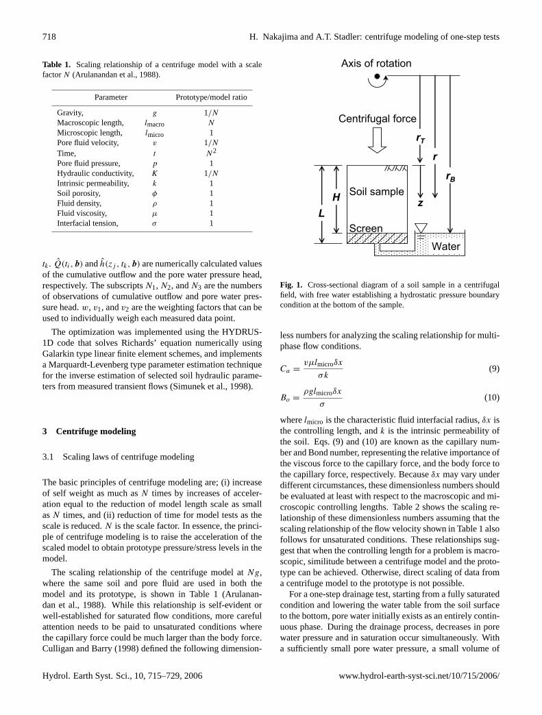
Fig. 1. Cross-sectional diagram of a soil sample in a centrifugalfield, with free water establishing a hydrostatic pressure boundarycondition at the bottom of the sample.
less numbers for analyzing the scaling relationship for multi-phase flow conditions.
Ca =vµlmicroδx
σk(9)
Bo =ρglmicroδx
σ(10)
wherelmicro is the characteristic fluid interfacial radius,δx isthe controlling length, andk is the intrinsic permeability ofthe soil. Eqs. (9) and (10) are known as the capillary num-ber and Bond number, representing the relative importance ofthe viscous force to the capillary force, and the body force tothe capillary force, respectively. Becauseδx may vary underdifferent circumstances, these dimensionless numbers shouldbe evaluated at least with respect to the macroscopic and mi-croscopic controlling lengths. Table 2 shows the scaling re-lationship of these dimensionless numbers assuming that thescaling relationship of the flow velocity shown in Table 1 alsofollows for unsaturated conditions. These relationships sug-gest that when the controlling length for a problem is macro-scopic, similitude between a centrifuge model and the proto-type can be achieved. Otherwise, direct scaling of data froma centrifuge model to the prototype is not possible.
For a one-step drainage test, starting from a fully saturatedcondition and lowering the water table from the soil surfaceto the bottom, pore water initially exists as an entirely contin-uous phase. During the drainage process, decreases in porewater pressure and in saturation occur simultaneously. Witha sufficiently small pore water pressure, a small volume of
Hydrol. Earth Syst. Sci., 10, 715–729, 2006 www.hydrol-earth-syst-sci.net/10/715/2006/
H. Nakajima and A.T. Stadler: centrifuge modeling of one-step tests 719
Table 2. Scaling relationship of dimensionless numbers.
Dimensionless number Prototype/model ratio
Macroscopic capillary number, Ca∗=
vµlmicrolmacro
σk1
Microscopic capillary number, Ca=vµl2micro
σk1/N
Macroscopic Bond number, Bo∗=
ρglmicrolmacro
σ1
Microscopic Bond number, Bo=ρgl2micro
σ1/N
water could eventually be isolated and form a pendular satu-ration condition. This is likely to be seen near the soil surfacewhere the pore water pressure is smallest in the soil sample.When drainage ceases and an equilibrium condition is es-tablished, pore water distributes from full saturation at thebottom to pendular saturation at the top, depending on thesample height. This means that the phase of the pore wateris initially entirely continuous, but that it varies being bothspatially and temporally discontinuous. Consequently, the“exact” similitude of one-step drainage is not likely satisfiedbetween a centrifuge model and the prototype; however, themagnitude of the deficiency in the scaling laws due to thecoexistence of different controlling lengths is not well un-derstood. If the deficiency is negligible, the application of aconventional scaling laws may still be reasonable in practice.
3.2 Uniformity of centrifugal acceleration
In this section, pore water pressure distributions in the cen-trifuge model and its prototype are compared to evaluate therationality of assuming a uniformly accelerated gravity fieldfor centrifuge modeling. Figure 1 shows a soil column oflengthH (i.e.,L minus thickness of screen layer) subject tocentrifugal rotation. For simplicity, pore water pressure dis-tribution at equilibrium condition is considered here. Waterpressure at the bottom of the soil is maintained at an atmo-spheric pressure. The pore water pressure under the equilib-rium condition can be expressed as a function of the angularvelocityω and the radiusr
p (r) =
∫ r
rB
ρrω2dr
=1
2ρω2
(r2
− r2B
) (11)
wherep (r) is pore water pressure at radiusr andrB is radiusat the bottom of the soil. Suppose the rotational speed is con-figured to create a pore water pressure of the model identicalto the prototype at a reference radiusrref,
1
2ρω2
(r2ref − r2
B
)= −ρg {N (rB − rref)} . (12)
-1 -0.75 -0.5 -0.25 0Normalized pore water pressure, p/(HρNg)
1
0.75
0.5
0.25
0
Nor
mar
ized
dep
th, z
/H
prototypecentrifuge model
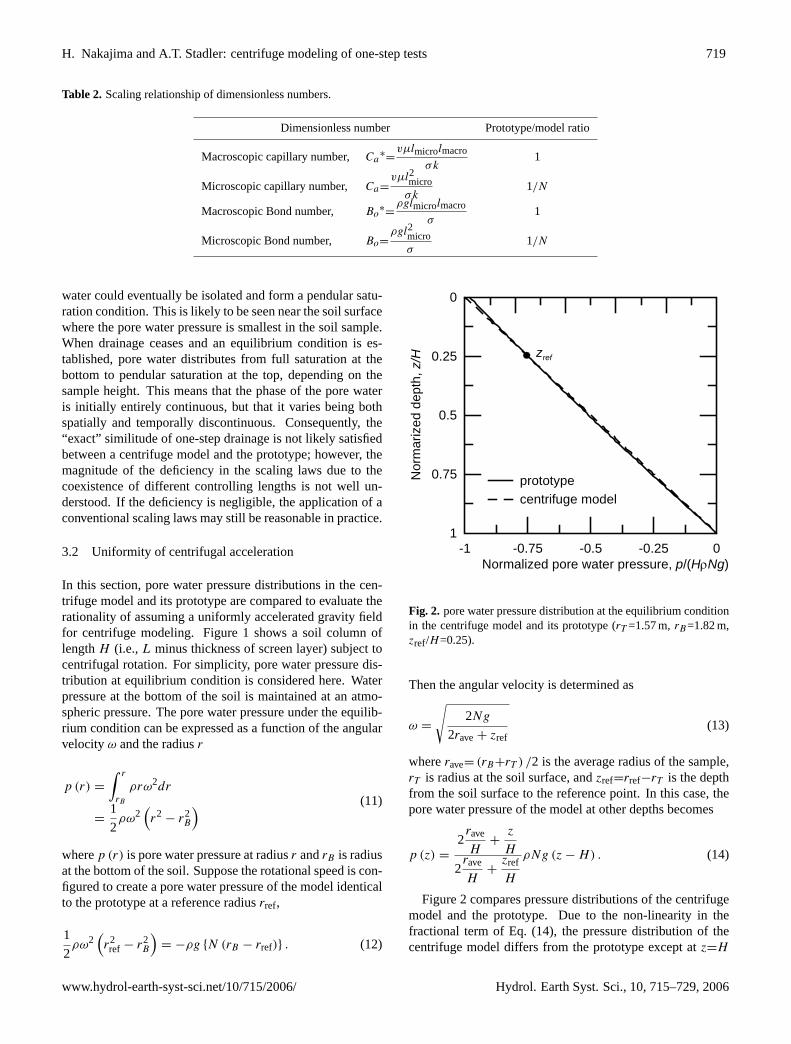
zref
Fig. 2. pore water pressure distribution at the equilibrium conditionin the centrifuge model and its prototype (rT =1.57 m,rB=1.82 m,zref/H=0.25).
Then the angular velocity is determined as
ω =
√2Ng
2rave+ zref(13)
whererave= (rB+rT ) /2 is the average radius of the sample,rT is radius at the soil surface, andzref=rref−rT is the depthfrom the soil surface to the reference point. In this case, thepore water pressure of the model at other depths becomes
p (z) =
2rave
H+
z
H
2rave
H+
zref
H
ρNg (z − H) . (14)
Figure 2 compares pressure distributions of the centrifugemodel and the prototype. Due to the non-linearity in thefractional term of Eq. (14), the pressure distribution of thecentrifuge model differs from the prototype except atz=H
www.hydrol-earth-syst-sci.net/10/715/2006/ Hydrol. Earth Syst. Sci., 10, 715–729, 2006
720 H. Nakajima and A.T. Stadler: centrifuge modeling of one-step tests
water
soil
at t = 0 -
at t = 0+
To DAQ system
CCD camera for monitoring water level in outflow collector
Miniature tensiometers
Electro-pneumatic solenoid valve
Outflow collector
Perforated plate
Filter paper
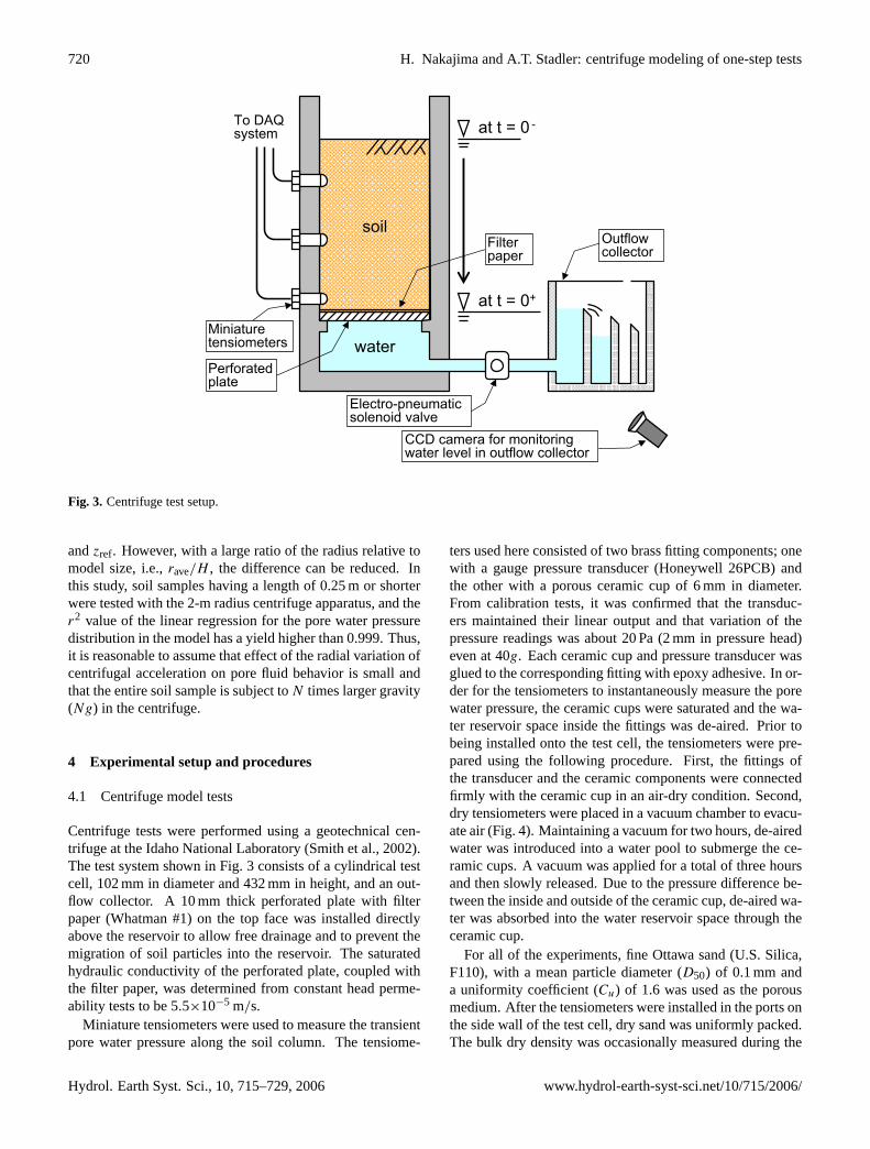
Fig. 3. Centrifuge test setup.
andzref. However, with a large ratio of the radius relative tomodel size, i.e.,rave/H , the difference can be reduced. Inthis study, soil samples having a length of 0.25 m or shorterwere tested with the 2-m radius centrifuge apparatus, and ther2 value of the linear regression for the pore water pressuredistribution in the model has a yield higher than 0.999. Thus,it is reasonable to assume that effect of the radial variation ofcentrifugal acceleration on pore fluid behavior is small andthat the entire soil sample is subject toN times larger gravity(Ng) in the centrifuge.
4 Experimental setup and procedures
4.1 Centrifuge model tests
Centrifuge tests were performed using a geotechnical cen-trifuge at the Idaho National Laboratory (Smith et al., 2002).The test system shown in Fig. 3 consists of a cylindrical testcell, 102 mm in diameter and 432 mm in height, and an out-flow collector. A 10 mm thick perforated plate with filterpaper (Whatman #1) on the top face was installed directlyabove the reservoir to allow free drainage and to prevent themigration of soil particles into the reservoir. The saturatedhydraulic conductivity of the perforated plate, coupled withthe filter paper, was determined from constant head perme-ability tests to be 5.5×10⁻⁵ m/s.
Miniature tensiometers were used to measure the transientpore water pressure along the soil column. The tensiome-
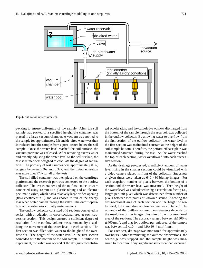
ters used here consisted of two brass fitting components; onewith a gauge pressure transducer (Honeywell 26PCB) andthe other with a porous ceramic cup of 6 mm in diameter.From calibration tests, it was confirmed that the transduc-ers maintained their linear output and that variation of thepressure readings was about 20 Pa (2 mm in pressure head)even at 40g. Each ceramic cup and pressure transducer wasglued to the corresponding fitting with epoxy adhesive. In or-der for the tensiometers to instantaneously measure the porewater pressure, the ceramic cups were saturated and the wa-ter reservoir space inside the fittings was de-aired. Prior tobeing installed onto the test cell, the tensiometers were pre-pared using the following procedure. First, the fittings ofthe transducer and the ceramic components were connectedfirmly with the ceramic cup in an air-dry condition. Second,dry tensiometers were placed in a vacuum chamber to evacu-ate air (Fig. 4). Maintaining a vacuum for two hours, de-airedwater was introduced into a water pool to submerge the ce-ramic cups. A vacuum was applied for a total of three hoursand then slowly released. Due to the pressure difference be-tween the inside and outside of the ceramic cup, de-aired wa-ter was absorbed into the water reservoir space through theceramic cup.
For all of the experiments, fine Ottawa sand (U.S. Silica,F110), with a mean particle diameter (D50) of 0.1 mm anda uniformity coefficient (Cu) of 1.6 was used as the porousmedium. After the tensiometers were installed in the ports onthe side wall of the test cell, dry sand was uniformly packed.The bulk dry density was occasionally measured during the
Hydrol. Earth Syst. Sci., 10, 715–729, 2006 www.hydrol-earth-syst-sci.net/10/715/2006/
H. Nakajima and A.T. Stadler: centrifuge modeling of one-step tests 721
to vacuum sourcede-aired water
supply
water pool
vacuum chamber
water reservoir
de-aired water
valve
tensiometers(initially air-dry condition)
Fig. 4. Saturation of tensiometers.
packing to ensure uniformity of the sample. After the soilsample was packed to a specified height, the container wasplaced in a large vacuum chamber. A vacuum was applied tothe sample for approximately 3 h and de-aired water was thenintroduced into the sample from a port located below the soilsample. Once the water level reached the soil surface, thevacuum pressure was released. After removing excess waterand exactly adjusting the water level to the soil surface, thetest specimen was weighed to calculate the degree of satura-tion. The porosity of test samples was approximately 0.37,ranging between 0.362 and 0.377, and the initial saturationwas more than 97% for all of the tests.
The soil filled container was then placed on the centrifugeplatform and the reservoir port was connected to the outflowcollector. The test container and the outflow collector wereconnected using 13 mm I.D. plastic tubing and an electro-pneumatic valve, which had a relatively large orifice opening(flow coefficient = 6) and was chosen to reduce the energyloss when water passed through the valve. The on/off opera-tion of the valve was virtually instantaneous.
The outflow collector consisted of 6 sections connected inseries, with a reduction in cross-sectional area at each suc-cessive section. This design ensured a sufficient degree ofresolution for the outflow volume measurements by visual-izing the movement of the water level in each section. Thefirst section was filled with water to the height of the over-flow slit. The height of the water level in the first sectioncoincided with the bottom of the soil sample. To initiate anexperiment, the valve was opened at the designated centrifu-
gal acceleration, and the cumulative outflow discharged fromthe bottom of the sample through the reservoir was collectedin the outflow collector. By allowing water to overflow fromthe first section of the outflow collector, the water level inthe first section was maintained constant at the height of thesoil sample bottom. Therefore, the perforated base plate wasmaintained saturated during the test. As the water reachedthe top of each section, water overflowed into each succes-sive section.
As the drainage progressed, a sufficient amount of waterlevel rising in the smaller sections could be visualized witha video camera placed in front of the collector. Snapshotsat given times were taken as 640–480 bitmap images. Foreach snapshot, number of pixels between the bottom of asection and the water level was measured. Then height ofthe water level was calculated using a correlation factor, i.e.,length per unit pixel which was determined from number ofpixels between two points of known distance. Knowing thecross-sectional area of each section and the height of wa-ter level, the cumulative outflow volume was obtained. Theaccuracy of the outflow volume measurements depends onthe resolution of the images plus size of the cross-sectionalarea of the sections. The accuracy ranged between±1500 to±400 mm3, and that for outflow per unit area of the samplewas between 1.9×10⁻¹ and 4.9×10⁻² mm3/mm2.
For each test, drainage was monitored for approximatelytwo hours. After terminating the outflow observations, thecentrifuge was stopped and the sample height was mea-sured to ascertain if any significant settlement had occurred.
www.hydrol-earth-syst-sci.net/10/715/2006/ Hydrol. Earth Syst. Sci., 10, 715–729, 2006
722 H. Nakajima and A.T. Stadler: centrifuge modeling of one-step tests
Table 3. Centrifuge test conditions.
Test code Applied Soil Height in Screen layer thicknessgravity height prototype scale in prototype scale[Ng] H [mm] N×H [m] N×(L−H) [mm]
10A, 10B 10 254 2.54 10020A, 20B 20 127 2.54 20040A, 40B 40 64 2.54 400
200
400
600
scal
ed c
umul
ativ
e ou
tflow
per
uni
t are
aQN=Q
<N
[mm
3 /mm
2 ]
1x100 1x101 1x10² 1x10³ 1x10⁴ 1x10⁵ 1x10⁶
scaled time, tN= t<N2 [min]
10A, 10B20A, 20B40A, 40BPrototype(10g)Prototype(20g)Prototype(40g)
+,,
.,/(,*
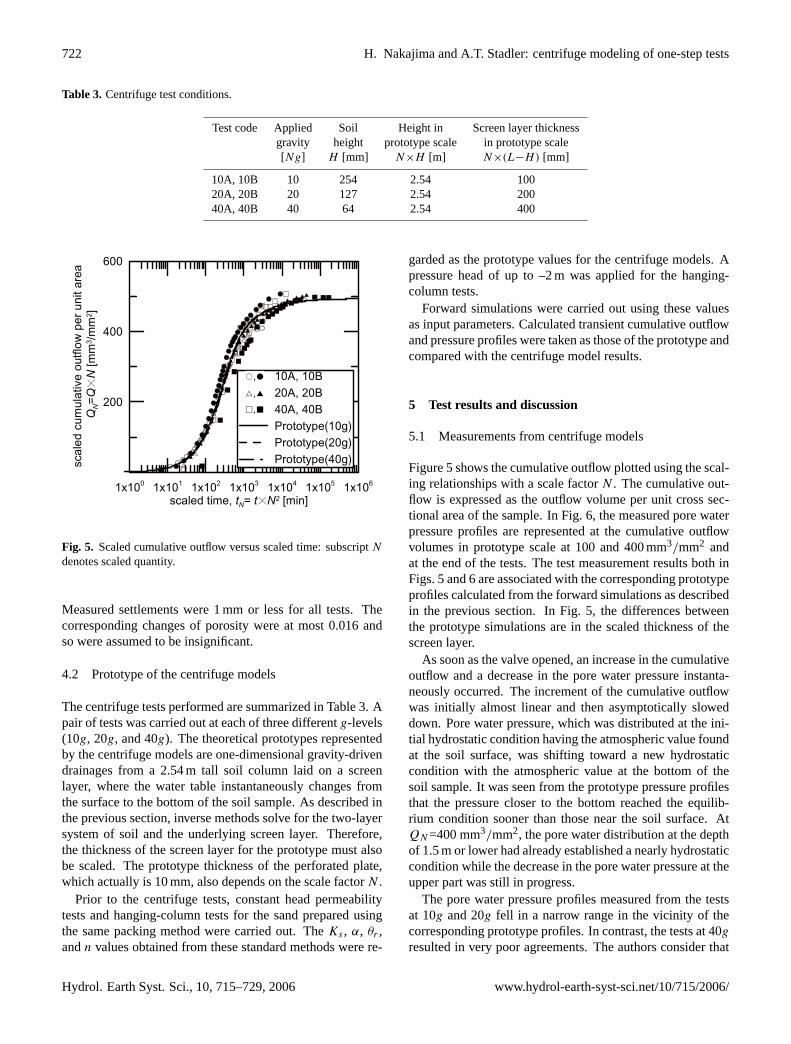
Fig. 5. Scaled cumulative outflow versus scaled time: subscriptN
denotes scaled quantity.
Measured settlements were 1 mm or less for all tests. Thecorresponding changes of porosity were at most 0.016 andso were assumed to be insignificant.
4.2 Prototype of the centrifuge models
The centrifuge tests performed are summarized in Table 3. Apair of tests was carried out at each of three differentg-levels(10g, 20g, and 40g). The theoretical prototypes representedby the centrifuge models are one-dimensional gravity-drivendrainages from a 2.54 m tall soil column laid on a screenlayer, where the water table instantaneously changes fromthe surface to the bottom of the soil sample. As described inthe previous section, inverse methods solve for the two-layersystem of soil and the underlying screen layer. Therefore,the thickness of the screen layer for the prototype must alsobe scaled. The prototype thickness of the perforated plate,which actually is 10 mm, also depends on the scale factorN .
Prior to the centrifuge tests, constant head permeabilitytests and hanging-column tests for the sand prepared usingthe same packing method were carried out. TheKs , α, θr ,andn values obtained from these standard methods were re-
garded as the prototype values for the centrifuge models. Apressure head of up to –2 m was applied for the hanging-column tests.
Forward simulations were carried out using these valuesas input parameters. Calculated transient cumulative outflowand pressure profiles were taken as those of the prototype andcompared with the centrifuge model results.
5 Test results and discussion
5.1 Measurements from centrifuge models
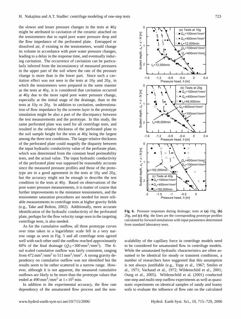
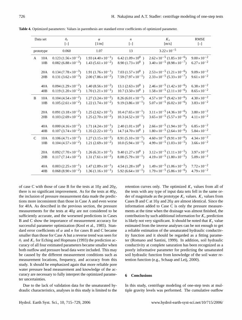
Figure 5 shows the cumulative outflow plotted using the scal-ing relationships with a scale factorN . The cumulative out-flow is expressed as the outflow volume per unit cross sec-tional area of the sample. In Fig. 6, the measured pore waterpressure profiles are represented at the cumulative outflowvolumes in prototype scale at 100 and 400 mm3/mm2 andat the end of the tests. The test measurement results both inFigs. 5 and 6 are associated with the corresponding prototypeprofiles calculated from the forward simulations as describedin the previous section. In Fig. 5, the differences betweenthe prototype simulations are in the scaled thickness of thescreen layer.
As soon as the valve opened, an increase in the cumulativeoutflow and a decrease in the pore water pressure instanta-neously occurred. The increment of the cumulative outflowwas initially almost linear and then asymptotically sloweddown. Pore water pressure, which was distributed at the ini-tial hydrostatic condition having the atmospheric value foundat the soil surface, was shifting toward a new hydrostaticcondition with the atmospheric value at the bottom of thesoil sample. It was seen from the prototype pressure profilesthat the pressure closer to the bottom reached the equilib-rium condition sooner than those near the soil surface. AtQN=400 mm3/mm2, the pore water distribution at the depthof 1.5 m or lower had already established a nearly hydrostaticcondition while the decrease in the pore water pressure at theupper part was still in progress.
The pore water pressure profiles measured from the testsat 10g and 20g fell in a narrow range in the vicinity of thecorresponding prototype profiles. In contrast, the tests at 40g
resulted in very poor agreements. The authors consider that
Hydrol. Earth Syst. Sci., 10, 715–729, 2006 www.hydrol-earth-syst-sci.net/10/715/2006/
H. Nakajima and A.T. Stadler: centrifuge modeling of one-step tests 723
the slower and lesser pressure changes in the tests at 40g
might be attributed to cavitation of the ceramic attached onthe tensiometers due to rapid pore water pressure drop andthe flow impedance of the perforated plate. Entrapped ordissolved air, if existing in the tensiometers, would changeits volume in accordance with pore water pressure changes,leading to a delay in the response time, and eventually induc-ing cavitation. The occurrence of cavitation can be particu-larly inferred from the inconsistency of measured pressuresin the upper part of the soil where the rate of the pressurechange is more than in the lower part. Since such a cav-itation effect was not seen in the tests at 10g and 20g, inwhich the tensiometers were prepared in the same manneras the tests at 40g, it is considered that cavitation occurredat 40g due to the more rapid pore water pressure change,especially at the initial stage of the drainage, than in thetests at 10g or 20g. In addition to cavitation, underestima-tion of flow impedance by the screenn layer in the prototypesimulation might be also a part of the discrepancy betweenthe test measurements and the prototype. In this study, thesame perforated plate was used for all centrifuge tests, andresulted in the relative thickness of the perforated plate tothe soil sample height for the tests at 40g being the largestamong the three test conditions. The larger relative thicknessof the perforated plate could magnify the disparity betweenthe input hydraulic conductivity value of the perforate plate,which was determined from the constant head permeabilitytests, and the actual value. The input hydraulic conductivityof the perforated plate was supposed be reasonably accuratesince the measured pressure profiles and those of the proto-type are in a good agreement in the tests at 10g and 20g,but the accuracy might not be enough to describe the testcondition in the tests at 40g. Based on observations of thepore water pressure measurements, it is matter of course thatfurther improvements to the miniature tensiometers, and thetensiometer saturation procedures are needed for more reli-able measurements in centrifuge tests at higher gravity fields(e.g., Take and Bolton, 2002). Additionally, more accurateidentification of the hydraulic conductivity of the perforatedplate, perhaps for the flow velocity range seen in the targetingcentrifuge tests, is also needed.
As for the cumulative outflow, all three prototype curvesover time taken in a logarithmic scale fell in a very nar-row range as seen in Fig. 5 and all centrifuge tests agreedwell with each other until the outflow reached approximately60% of the final drainage (QN=300 mm3/mm2). The fi-nal scaled cumulative outflow was fairly consistent, rangingfrom 472 mm3/mm2 to 511 mm3/mm2. A strong gravity de-pendency on cumulative outflow was not identified but theresults seem to be rather scattered in a narrow range. How-ever, although it is not apparent, the measured cumulativeoutflows are likely to be more than the prototype values thatended at 490 mm3/mm2 at 1×10⁵ min.
In addition to the experimental accuracy, the flow ratedependency of the unsaturated flow process and the non-
2
1
0
Sca
led
dept
h, zN
=z<N
[m]
-1.6 -1.2 -0.8 -0.4 0 0.4Pressure head, h [m]
(a) Tests at 10gQN=100mm3/mm2
QN=400mm3/mm2
tN=12,000min
+,,
$,&
(,*
QN=100mm3/mm2
QN=400mm3/mm2
tN=12,000min
2
1
0
Scal
ed d
epth
, zN =
z<N
[m]
-1.6 -1.2 -0.8 -0.4 0 0.4Pressure head, h [m]
(b) Tests at 20gQN=100mm3/mm2
QN=400mm3/mm2
tN=48,000min
2
1
0S
cale
d de
pth,
zN =
z<N
[m]
-2 -1.5 -1 -0.5 0Pressure head, h [m]
(c) Tests at 40gQN=100mm3/mm2
QN=400mm3/mm2
tN=192,000min
+,,
$,&
(,*
QN=100mm3/mm2
QN=400mm3/mm2
tN=48,000min
+,,
$,&
(,*
QN=100mm3/mm2
QN=400mm3/mm2
tN=192,000min
Fig. 6. Pressure responses during drainage; tests at(a) 10g, (b)20g, and(c) 40g: the lines are the corresponding prototype profilescalculated by forward simulations with input parameters determinedfrom standard laboratory tests.
scalability of the capillary force in centrifuge models needto be considered for unsaturated flow in centrifuge models.While the unsaturated hydraulic characteristics are often as-sumed to be identical for steady or transient conditions, anumber of researchers have suggested that this assumptionis not always justifiable (e.g., Topp et al., 1967; Smiles etal., 1971; Vachaud et al., 1972; Wildenschild et al., 2001;Oung et al., 2005). Wildenschild et al. (2001) conductedone-step and multi-step outflow experiments as well as quasi-static experiments on identical samples of sandy and loamysoils to evaluate the influence of flow rate on the calculated
www.hydrol-earth-syst-sci.net/10/715/2006/ Hydrol. Earth Syst. Sci., 10, 715–729, 2006
724 H. Nakajima and A.T. Stadler: centrifuge modeling of one-step tests
0 0.1 0.2 0.3 0.4Volumetric water content, s [-]
CaseC (40g)Prototype40A40B
0 0.1 0.2 0.3 0.4Volumetric water content, s [-]
CaseC (20g)Prototype20A20B
0 0.1 0.2 0.3 0.4Volumetric water content, s [-]
0
-0.4
-0.8
-1.2
-1.6
-2
Pre
ssur
ehe
ad,h
[m] CaseC (10g)
Prototype10A10B
0 0.1 0.2 0.3 0.4Volumetric water content, s [-]
CaseB (40g)Prototype40A40B
0 0.1 0.2 0.3 0.4Volumetric water content, s [-]
CaseB (20g)Prototype20A20B
0 0.1 0.2 0.3 0.4Volumetric water content, s [-]
0
-0.4
-0.8
-1.2
-1.6
-2
Pre
ssur
ehe
ad,h
[m] CaseB (10g)
Prototype10A10B
0 0.1 0.2 0.3 0.4Volumetric water content, s [-]
CaseA (40g)Prototype40A40B
0 0.1 0.2 0.3 0.4Volumetric water content, s [-]
CaseA (20g)Prototype20A20B
0 0.1 0.2 0.3 0.4Volumetric water content, s [-]
0
-0.4
-0.8
-1.2
-1.6
-2
Pre
ssur
ehe
ad,h
[m] CaseA (10g)
Prototype10A10B
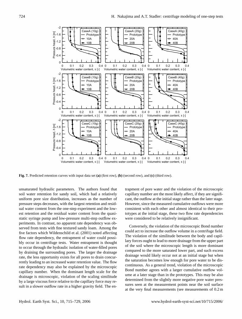
Fig. 7. Predicted retention curves with input data set(a) (first row), (b) (second row), and(c) (third row).
unsaturated hydraulic parameters. The authors found thatsoil water retention for sandy soil, which had a relativelyuniform pore size distribution, increases as the number ofpressure steps decreases, with the largest retention and resid-ual water content from the one-step experiment and the low-est retention and the residual water content from the quasi-static syringe pump and low-pressure multi-step outflow ex-periments. In contrast, no apparent rate dependency was ob-served from tests with fine textured sandy loam. Among thefive factors which Wildenschild et al. (2001) noted affectingflow rate dependency, the entrapment of water could possi-bly occur in centrifuge tests. Water entrapment is thoughtto occur through the hydraulic isolation of water-filled poresby draining the surrounding pores. The larger the drainagerate, the less opportunity exists for all pores to drain concur-rently leading to an increased water retention value. The flowrate dependency may also be explained by the microscopiccapillary number. When the dominant length scale for thedrainage is microscopic, violation of the scaling similitudeby a large viscous force relative to the capillary force may re-sult in a slower outflow rate in a higher gravity field. The en-
trapment of pore water and the violation of the microscopiccapillary number are the most likely affect, if they are signifi-cant, the outflow at the initial stage rather than the later stage.However, since the measured cumulative outflows were moreconsistent with each other and almost identical to their pro-totypes at the initial stage, these two flow rate dependencieswere considered to be relatively insignificant.
Conversely, the violation of the microscopic Bond numbercould act to increase the outflow volume in a centrifuge field.The violation of the similitude between the body and capil-lary forces ought to lead to more drainage from the upper partof the soil where the microscopic length is more dominantcompared to the more saturated lower part, and such excessdrainage would likely occur not at an initial stage but whenthe saturation becomes low enough for pore water to be dis-continuous. As a general trend, violation of the microscopicBond number agrees with a larger cumulative outflow vol-ume at a later stage than in the prototypes. This may be alsodetermined from the slightly more negative pore water pres-sures seen at the measurement points near the soil surfaceat the very final measurements (see measurements of 0.2 m
Hydrol. Earth Syst. Sci., 10, 715–729, 2006 www.hydrol-earth-syst-sci.net/10/715/2006/
H. Nakajima and A.T. Stadler: centrifuge modeling of one-step tests 725
deep at 12 000 min in 10B, 0.4 m deep at 48 000 min in 20B,and 0.25 m and 0.5 m deep at 192 000 min in 40B), while itis seen from the tests at 10g and 20g that the pressure mea-surements at a depth approximately below 1.5 m resulted ingood agreements with the prototype profiles even at the finalstage. However, this inference is not firmly conclusive sincean apparent gravity dependence was not observed from thecumulative outflow and pressure measurements in the 40g
tests seem insufficiently trustworthy.Nevertheless, the excellent agreements of the pressure pro-
files between the prototypes and the centrifuge models at 10g
and 20g and the narrow range which the cumulative outflowmeasurements fell in indicate that the scaling similitude ofunsaturated flow was reasonably conserved at least up to 20g
and highlight the possibility to use the centrifuge modelingtechnique for one-step parameter estimations.
5.2 Inverse analysis results
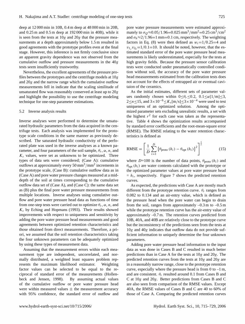
Inverse analyses were performed to determine the unsatu-rated hydraulic parameters from the data acquired in the cen-trifuge tests. Each analysis was implemented for the proto-type scale conditions in the same manner as previously de-scribed. The saturated hydraulic conductivity of the perfo-rated plate was used in the inverse analyses as a known pa-rameter, and four parameters of the soil sample,θr , α, n, andKs values, were set as unknowns to be optimized. Threetypes of data sets were considered; (Case A): cumulativeoutflows at approximately every 50 mm3/mm2 increments inthe prototype scale, (Case B): cumulative outflow data as in(Case A) and pore water pressure changes measured at a mid-depth of the soil at times corresponding to the cumulativeoutflow data set of (Case A), and (Case C): the same data setas (B) plus the final pore water pressure measurements frommultiple locations. Inverse analyses using cumulative out-flow and pore water pressure head data as functions of timefrom one-step tests were carried out to optimizeθr , α, n, andKs by Eching and Hopmans (1993). Their results showedimprovements with respect to uniqueness and sensitivity byadding the pore water pressure head measurements and goodagreements between optimized retention characteristics andthose obtained from direct measurements. Therefore, a pri-ori, we assumed that the soil retention characteristics takingthe four unknown parameters can be adequately optimizedby using these types of measurement data.
Assuming that the measurement errors within each mea-surement type are independent, uncorrelated, and nor-mally distributed, a weighted least squares problem rep-resents the maximum likelihood estimator. Weightingfactor values can be selected to be equal to the re-ciprocal of standard error of the measurements (Hollen-beck and Jensen, 1998). By assuming actual valuesof the cumulative outflow or pore water pressure headwere within measured values± the measurement accuracywith 95% confidence, the standard error of outflow and
pore water pressure measurements were estimated approxi-mately toσQ≈0.05/1.96=0.025 mm3/mm2
=0.25 cm3/cm2
andσh≈2/1.96=1 mm=0.1 cm, respectively. The weightingfactors in Eq. (8) were then defined aswi=1/0.25=4 andv1j
v2k=1/0.1=10. It should be noted, however, that the es-
timated standard error of the pore water pressure head mea-surements is likely underestimated, especially for the tests athigh gravity fields. Because the pressure sensor calibrationtests were conducted under pneumatically controlled condi-tion without soil, the accuracy of the pore water pressurehead measurements estimated from the calibration tests doesnot account for the effects of entrapped air or eventual cavi-taion of the ceramics.
As the initial estimates, different sets of parameter val-ues randomly chosen within 0≤θr≤0.2, 0.1≤α[1/m]≤3,2≤n≤15, and 3×10⁻⁶
≤Ks[m/s]≤3×10−4 were used to testuniqueness of an optimized solution. Among the opti-mized parameter sets excluding unrealistic results, a set withthe highestr2 for each case was taken as the representa-tive. Table 4 shows the optimization results accompaniedby standard error coefficients and the root-mean-square error(RMSE). The RMSE relating to the water retention charac-teristics is defined as
RMSE=
[1
D
D∑i=1
{θproto(hi) − θopt (hi)
}2
] 12
(15)
whereD=100 is the number of data points,θproto(hi) andθopt (hi) are water contents calculated with the prototype orthe optimized parameter values at pore water pressure head= hi , respectively. Figure 7 shows the predicted retentioncurves.
As expected, the predictions with Case A are mostly muchdifferent from the prototype retention curve.θr ranges from0.082 to 0.134 and an air-entry value, which is defined asthe pressure head when the pore water can begin to drainfrom the soil, ranges from approximately –0.3 m to –0.5 mwhile the prototype retention curve has the air-entry value ofapproximately –0.7 m. The retention curves predicted from10B, 40A, and 40B are relatively close to the prototype curvebut the inconsistency of the predictions seen from the tests at10g and 40g indicates that outflow data do not provide suf-ficient information to uniquely determine the four unknownparameters.
Adding pore water pressure head information to the inputdata as was done in Cases B and C resulted in much betterpredictions than in Case A for the tests at 10g and 20g. Thepredicted retention curves from the tests at 10g and 20g arein a reasonably narrow range, close to the prototype retentioncurve, especially where the pressure head is from 0 to –1 m,and are consistent.θr resulted around 0.1 from Cases B andC at 10g and 20g. Better predictions from Cases B and Care also seen from comparison of the RMSE values. Except40A, the RMSE values of Cases B and C are 40 to 60% ofthose of Case A. Comparing the predicted retention curves
www.hydrol-earth-syst-sci.net/10/715/2006/ Hydrol. Earth Syst. Sci., 10, 715–729, 2006
726 H. Nakajima and A.T. Stadler: centrifuge modeling of one-step tests
Table 4. Optimized parameters: Values in parenthesis are standard error coefficients of optimized parameter.
Data set θr α n Ks RMSE[–] [1/m] [–] [m/s] [–]
prototype 0.060 1.07 13 3.22×10⁻⁵
A 10A 0.123 (1.56×10⁻²) 1.93 (4.40×10⁻¹) 6.42 (1.09×100 ) 2.62×10⁻⁵ (1.85×10⁻⁶) 9.00×10⁻²
10B 0.082 (6.88×10⁻³) 1.43 (5.61×10⁻²) 8.90 (1.73×100 ) 3.40×10⁻⁵ (8.98×10⁻⁷) 6.27×10⁻²
20A 0.134 (7.78×10⁻³) 1.91 (1.76×10⁻¹) 7.03 (1.57×100 ) 2.53×10⁻⁵ (1.21×10⁻⁶) 9.09×10⁻²
20B 0.131 (3.62×10⁻³) 2.00 (7.86×10⁻²) 7.59 (7.97×10⁻¹) 2.33×10⁻⁵ (5.33×10⁻⁷) 9.61×10⁻²
40A 0.094 (1.29×10⁻²) 1.40 (8.56×10⁻²) 13.1 (2.63×100 ) 2.46×10⁻⁵ (1.42×10⁻⁶) 6.38×10⁻²
40B 0.119 (1.20×10⁻²) 1.70 (1.21×10⁻¹) 10.7 (3.50×100 ) 1.58×10⁻⁵ (2.11×10⁻⁶) 8.65×10⁻²
B 10A 0.104 (4.54×10⁻²) 1.27 (3.24×10⁻²) 8.26 (6.01×10⁻¹) 4.57×10⁻⁵ (9.42×10⁻⁶) 4.30×10⁻²
10B 0.105 (2.61×10⁻²) 1.22 (1.74×10⁻²) 9.19 (3.86×10⁻¹) 5.07×10⁻⁵ (6.02×10⁻⁶) 3.83×10⁻²
20A 0.091 (3.18×10⁻²) 1.25 (2.62×10⁻²) 10.4 (7.65×10⁻¹) 3.11×10⁻⁵ (4.36×10⁻⁶) 3.80×10⁻²
20B 0.103 (2.69×10⁻²) 1.25 (2.70×10⁻²) 10.3 (4.52×10⁻¹) 3.65×10⁻⁵ (5.57×10⁻⁶) 4.11×10⁻²
40A 0.000 (4.16×10⁻²) 1.71 (4.24×10⁻¹) 2.40 (1.01×100 ) 2.66×10⁻⁵ (1.94×10⁻⁵) 6.85×10⁻²
40B 0.107 (3.74×10⁻²) 1.35 (2.22×10⁻²) 14.7 (4.70×100 ) 1.80×10⁻⁵ (2.64×10⁻⁶) 5.84×10⁻²
C 10A 0.106 (4.71×10⁻²) 1.27 (3.15×10⁻²) 8.91 (5.10×10⁻¹) 4.60×10⁻⁵ (9.91×10⁻⁶) 4.34×10⁻²
10B 0.104 (4.57×10⁻²) 1.21 (2.69×10⁻²) 10.0 (5.94×10⁻¹) 4.99×10⁻⁵ (1.03×10⁻⁵) 3.66×10⁻²
20A 0.092 (7.70×10⁻²) 1.26 (6.31×10⁻²) 9.40 (1.27×100 ) 3.12×10⁻⁵ (1.11×10⁻⁵) 3.97×10⁻²
20B 0.117 (7.14×10⁻²) 1.31 (7.61×10⁻²) 8.08 (5.79×10⁻¹) 4.19×10⁻⁵ (1.80×10⁻⁵) 5.09×10⁻²
40A 0.003 (2.25×10⁻¹) 1.47 (2.89×10⁻¹) 4.54 (1.28×100 ) 1.49×10⁻⁵ (1.06×10⁻⁵) 7.72×10⁻²
40B 0.068 (8.90×10⁻²) 1.36 (1.16×10⁻¹) 5.92 (6.64×10⁻¹) 1.79×10⁻⁵ (5.86×10⁻⁶) 4.79×10⁻²
of case C with those of case B for the tests at 10g and 20g,there is no significant improvement. As for the tests at 40g,the inclusion of pressure measurement data made the predic-tions more inconsistent than those in Case A and even worsefor 40A. As described in the previous section, the pressuremeasurements for the tests at 40g are not considered to besufficiently accurate, and the worsened predictions in CasesB and C show the importance of measurement accuracy forsuccessful parameter optimization (Kool et al., 1985). Stan-dard error coefficients ofα andn for cases B and C becamesmaller than those for Case A but a reverse trend was seen forθr andKs for Eching and Hopmans (1993) the prediction ac-curacy of all four estimated parameters became smaller whenboth outflow and pressure head data were included. This maybe caused by the different measurement conditions such asmeasurement locations, frequency, and accuracy from thisstudy. It should be emphasized again that more reliable porewater pressure head measurement and knowledge of the ac-curacy are necessary to fully interpret the optimized parame-ter uncertainties.
Due to the lack of validation data for the unsaturated hy-draulic characteristics, analyses in this study is limited to the
retention curves only. The optimizedKs values from all ofthe tests with any type of input data sets fell in the same or-der of magnitude as the prototypeKs values.Ks values fromCases B and C at 10g and 20g are almost identical. Since theinformation added to Case C is only the pressure measure-ments at the time when the drainage was almost finished, thecontribution by such additional information forKs predictionis likely not very significant. It should be noted thatKs valueestimated from the inverse analyses can be not enough to geta reliable estimation of the unsaturated hydraulic conductiv-ity function and it should be regarded as a fitting parame-ter (Romano and Santini, 1999). In addition, soil hydraulicconductivity at complete saturation has been recognized as apoorly informative parameter for predicting the unsaturatedsoil hydraulic function from knowledge of the soil water re-tention function (e.g., Schaap and Leij, 2000).
6 Conclusions
In this study, centrifuge modeling of one-step tests at mul-tiple gravity levels was performed. The cumulative outflow
Hydrol. Earth Syst. Sci., 10, 715–729, 2006 www.hydrol-earth-syst-sci.net/10/715/2006/

H. Nakajima and A.T. Stadler: centrifuge modeling of one-step tests 727
and transient pore water pressure heads at several locationswere measured and compared with the prototype data, whichwere calculated from forward simulations using input param-eters determined from standard laboratory tests, based on thecentrifuge scaling laws. The measured cumulative outflowand pore water pressure were then used as input data for pa-rameter estimations by the inverse method.
The scaled cumulative outflow curves showed good agree-ment with the prototype curve until a point when approxi-mately 60% of the final outflow volume was drained, andthen showed a tendency to become slightly larger than theprototype at a later stage of the drainage. It was consideredthat a violation of the scaling similitude for body force rela-tive to capillary force occurred when and where the govern-ing length scale became microscopic. However, it should benoted that an apparent gravity dependency was not identifiedand that the overall cumulative outflow curves still fell in arelatively narrow range. Pressure measurements also showedgood agreements with the prototype profiles, except for thetests at 40g. It was considered that cavitation occurred in thetensiometers and resulted in the pressure measurements forthe tests at 40g being unsuccessful. Nevertheless, the reason-able agreements of cumulative outflow and pressure profilesinfer that unsaturated flow during monotonic drainage wasreasonably scaled in the centrifuge model, at least up to 20g.
The estimated unsaturated parameters compared reason-ably well with those determined using standard laboratorytests when accurate pore water pressure measurements wereincluded as input data, while the estimations with only cu-mulative outflow data led to poorer and less consistent re-sults. The addition of pressure measurements, even at a sin-gle location, improved accuracy and consistency for reten-tion characteristics. However, unclear quantification of theactual pore water pressure measurement accuracy during thetests precluded full evaluation of the uncertainties and sen-sivity of the estimated parameters. For success of parameterestimations, the analyses of parameter uncertainty and sen-sitivity are imperative along with knowing the measurementaccuracy as a prerequisite.
Characterizations of unsaturated hydraulic parameters uti-lizing centrifugal force are often used, but are typically basedon an equilibrium condition or a steady state. Coupling theapplication of a centrifugal force with the inverse method isadvantageous in respect to achieving a shorter testing time.Recently Simunek and Nimmo (2005) performed multirota-tion experiments with a relatively small size centrifuge forparameter estimations using a numerical code that was spe-cially developed to take into account the radial variations ofcentrifugal gravity. They showed that centrifuge tests notonly offer significant time savings but also provide signifi-cantly more information for the parameter estimation proce-dure compared to the usual one-step or multistep outflow ex-periments. While the methodology by Simunek and Nimmo(2005) is advantageous, particularly with respect to cost-effectiveness and the capability to carry to a very high grav-
ity field using the small centrifuge apparatus, the applica-tion of the centrifuge “modeling” technique with a relativelylarger centrifuge apparatus offers different benefits. Largecentrifuges can mount a much larger soil sample and thusprovide more freedom to implement a variety of instrumen-tations at multiple locations, controls of initial and boundaryconditions are also much easier, and special consideration ofthe radial variation of centrifugal acceleration is not neces-sary for the inverse calculation. The test setup developed forthis study enabled us to measure both cumulative outflow andtransient pressure data that constitute useful information forparameter estimations.
Based on the results in this investigation, the conservationof scaling similitude for unsaturated flow process, which islikely not exactly conserved, was however reasonably as-sured up to 20g. This indicates the potential for success-ful application of the centrifuge modeling technique to otherstudies such as contaminant transport under unsaturated con-ditions. To more confidently use the centrifuge modelingtechnique for unsaturated flow problems, further investiga-tions and improvements in experimental techniques are nec-essary. In particular, improving the point-wise measurementsof rapid and large pore water pressure changes is a critical is-sue. With more reliable pore water pressure measurementsone should be able to gain information on the optimal exper-imental and measurement design for inverse methods.
Acknowledgements.This work was supported by the BBWICorporate Funded Research and Development and the DOEEnvironmental Systems Research and Analysis Programs. Theauthors are grateful to J. Lord and J. Johnson for technical support.The authors also acknowledge the valuable comments by J. Nimmoof U.S. Geological Survey, and M. Takeda and K. Ito of theNational Institute of Advanced Industrial Science and Technology(AIST). The authors also appreciate helpful comments from theEditor N. Romano.
Edited by: N. Romano
References
Alemi, M. H., Nielsen, D. R., and Biggar, J. W.: Determining thehydraulic conductivity of soil cores by centrifugation, Soil Sci.Soc. Am. J., 40, 212–218, 1976.
Arulanandan, K., Thompson, P. Y., Kutter, B. L., Meegoda, N. J.,Muraleetharan, K. K., and Yogachandran, C.: Centrifuge Mod-eling of Transport Processes for Pollutants in Soils, J. Geotech.Eng.-Ascel, 114(2), 185–205, 1988.
Burkhart, S., Davies, M. C. R., Depountis, N., Harris, C., andWilliams, K. P.: scaling laws for infiltration and drainage testsusing a geotechnical centrifuge, Proceeding of the InternationalSymposium on Physical Modelling and Testing in EnvironmentalGeotechnics, 191–198, 2000.
Cooke, B.: Determination of soil hydraulic properties, InternationalConference Centrifuge 94, 411–416, 1994.
www.hydrol-earth-syst-sci.net/10/715/2006/ Hydrol. Earth Syst. Sci., 10, 715–729, 2006
728 H. Nakajima and A.T. Stadler: centrifuge modeling of one-step tests
Cooke, A. B. and Mitchell, R. J.: Physical modelling of a dissolvedcontaminant in an unsaturated sand, Can. Geotech. J., 28, 829–833, 1991.
Crancon, C. G., Pili, E., Dutheil, S., and Gaudet, J. P.: Mod-elling of capillary rise and water retention in centrifuge tests us-ing time domain reflectometry, Proceeding of the InternationalSymposium on Physical Modelling and Testing in Environmen-tal Geotechnics, 199–206, 2000.
Culligan, P. J. and Barry, D. A.: Similitude requirements for mod-elling NAPL movement with a geotechnical centrifuge, Proceed-ings of the Institution of Civil Engineers-Geotechnical Engineer-ing, 131(3), 180–186, 1998.
Eching, S. O. and Hopmans, J. W.: Optimization of Hydraulic Func-tions from Transient Outflow and Soil-Water Pressure Data, SoilSci. Soc. Am. J., 57(5), 1167–1175, 1993.
Eching, S. O., Hopmans, J. W., and Wendroth, O.: UnsaturatedHydraulic Conductivity from Transient Multistep Outflow andSoil-Water Pressure Data, Soil Sci. Soc. Am. J., 58(3), 687–695,1994.
Garnier, J.: Physical models in geotechnics: state of the art andrecent advances, First Coulomb lecture (Caquot Conference, 3rdOctober, Paris), 1–51, 2001.
Goforth, G. F., Townsend, F. C., and Bloomquist, D.: Saturated andunsaturated fluid flow in a centrifuge, Centrifuge 91. Proceedingsof the International Conference on Centrifuge Modelling, 497–502, 1991.
Hagoort, J.: Oil-Recovery by Gravity Drainage, Soc. PetroleumEng. J., 20(3), 139–150, 1980.
Hassler, G. L. and Brunner, E.: Measurement of capillary pressuresin small core samples, Transactions of the American Institute ofMining and Metallurgical Engineers, 160, 114–123, 1945.
Hensley, P. J. and Schofield, A. N.: Accelerated Physical Modelingof Hazardous-Waste Transport, Geotechnique, 41(3), 447–465,1991.
Hollenbeck, K. J. and Jensen, K. H.: Maximum-likelihood estima-tion of unsaturated hydraulic parameters, J. Hydrol., 210, 192–205, 1998.
Hopmans, J. W., Vogel, T., and Koblik, P. D.: X-ray tomography ofsoil water distribution in one-step outflow experiments, Soil Sci.Soc. Am. J., 56, 355–362, 1992.
Hopmans, J. W., Simunek, J., Romano, N., and Durner, W.: Simul-taneous determination of water transmission and retention prop-erties. Inverse Methods, in: Methods of Soil Analysis. Part 4.Physical Methods, edited by: Dane, J. H. and Topp, G. C., SoilSci. Soc. Am., 5, 963–1008, 2002.
Khalifa, A., Garnier, J., Thomas, P., and Rault, G.: scaling lawsof water flow in centrifuge models, International Symposium onPhysical Modelling and Testing in Environmental Geotechnics,56, 207–216, 2000.
Khanzode, R. M., Vanapalli, S. K., and Fredlund, D. G.: Measure-ment of soil-water characteristic curves for fine-grained soils us-ing a small-scale centrifuge, Can. Geotech. J., 39, 1209–1217,2000.
Knight, M. A., Cooke, A. B., and Mitchell, R. J.: Scaling of themovement and fate of contaminant releases in vadose zone bycentrifuge testing, International Symposium on Physical Mod-elling and Testing in Environmental Geotechnics, 233–242,2000.
Kool, J. B., Parker, J. C., and van Genuchten, M. T.: DeterminingSoil Hydraulic-Properties from One-Step Outflow Experimentsby Parameter-Estimation .1. Theory and Numerical-Studies Cen-trifuge tests on moisture and permeability in sand, Soil Sci. Soc.Am. J., 49(6), 1348–1354, 1985.
Mualem, Y.: A new model for predicting the hydraulic conductivityof unsaturated porous media, Water Resour. Res. 12, 513–522,1976.
Nakajima, H., Hirooka, A., Takemura, J., and Marino, M. A.: Cen-trifuge modeling of one-dimensional subsurface contamination,J. Am. Water Resour. Assoc., 34(6) 1415–1425, 1998.
Nakajima, H., Kutter, B. L., Ginn, T. R., Chang, D. P., and Marino,M. A.: An experimental study of LNAPL lens formation using acentrifuge, Proceedings of the 16th International Conference onSoil Mechanics and Geotechnical Engineering, 4, 2425–2428,2005.
Nimmo, J. R., Rubin, J., and Hammermeister, D. P.: UnsaturatedFlow in a Centrifugal Field – Measurement of Hydraulic Con-ductivity and Testing of Darcy Law, Water Resour. Res., 23(1),124–134, 1987.
Oung, O., Hassanizadeh, S. M., and Bezuijen, A.: Two-phase flowexperiments in a geocentrifuge and the significance of dynamiccapillary pressure effect, J. Porous Media, 8(3), 247–257, 2005.
Parker, J. C., Kool, J. B., and van Genuchten, M. T.: DeterminingSoil Hydraulic-Properties from One-Step Outflow Experimentsby Parameter-Estimation .2. Experimental Studies, Soil Sci. Soc.Am. J., 49(6), 1354–1359, 1985.
Rezzoug, A., Konig, D., and Triantafyllidis, T.: scaling laws forcentrifuge modeling of capillary rise in sandy soils, J. Geotech.Geoenviron. Eng., 130(6), 615–620, 2004.
Romano, N. and Santini, A.: Determining soil hydraulic func-tions from evaporation experiments by a parameter estimationapproach: Experimental verifications and numerical studies, Wa-ter Resour. Res., 35(11), 3343–3359, 1999.
Russell, M. B. and Richards, L. A.: The determination of soil mois-ture energy relations by centrifugation, Soil Sci. Soc. Am. Pro-ceedings, 3, 65–69, 1938.
Schaap, M. G. and Leij, F. J.: Improved prediction of unsaturatedhydraulic conductivity with the Mualem-van Genuchten model,Soil Sci. Soc. Am. J., 64, 843–851, 2000.
Simunek, J., Sejna, M., and van Genuchten, M. T.: The HYDRUS-1D software package for simulation of the one-dimensionalmovement of water, heat and multiple solutes in variably satu-rated media, Version 2.0, International Ground Water ModellingCenter, IGWMC-TPS-70, 1998.
Simunek, J. and Nimmo, J. R.: Estimating soil hydraulic parame-ters from transient flow experiments in a centrifuge using param-eter optimization technique, Water Resour. Res., 41(4), W04015,doi:10.1029/2004WR003379, 2005.
Smiles, D., Vachaud, G., and Vauclin, M.: A test of the uniquenessof the soil moisture characteristic during transient nonhystereticflow of water in a rigid soil, Soil Sci. Soc. Am. Proceedings, 35,534–539, 1971.
Smith, R. W., Payne, S. M., and Miller, D. L.: INEEL environ-mental geocentrifuge facility developments International Confer-ence on Physical Modelling in Geotechnics – ICPMG 02, 55–58,2002.
Take, W. A. and Bolton, M. D.: A new device for the measure-ment of negative pore water pressures in centrifuge models, In-
Hydrol. Earth Syst. Sci., 10, 715–729, 2006 www.hydrol-earth-syst-sci.net/10/715/2006/
H. Nakajima and A.T. Stadler: centrifuge modeling of one-step tests 729
ternational Conference on Physical Modelling in Geotechnics –ICPMG 02, 89–94, 2002.
Taylor, R. N.: Geotechnical Centrifuge Technology, Blackie Aca-demic and Professional, 1995.
Thorel, L., Noblet, S., Garnier, J., and Bisson, A.: Capillary riseand drainage flow through a centrifuged porous medium, Pro-ceeding of the International Symposium on Physical Modellingand Testing in Environmental Geotechnics, 251–258, 2000.
Toorman, A. F., Wierenga, P. J., and Hills, R. G.: Parameter estima-tion of hydraulic properties from one-step outflow data, WaterResour. Res., 28(11), 3021–3028, 1992.
Topp, G. C., Klute, A., and Peters, D. B.: Comparison of watercontent-pressure head data obtained by equilibrium, steady-stateand unsteady state methods, Soil Sci. Soc. Am. Proceedings, 31,312–314, 1967.
Vachaud, G., Vauclin, M., and Wakil, M.: A study of the uniquenessof the soil moisture characteristic during desorption by verticaldrainage, Soil Sci. Soc. Am. Proceedings, 36, 531–532, 1972.
van Dam, J. C., Stricker, J. N. M., and Droogers, P.: Inverse Methodfor determining soil hydraulic functions from one-step outflowexperiments, Soil Sci. Soc. Am. J., 56, 1042–1050, 1992.
van Dam, J. C., Stricker, J. N. M., and Droogers, P.: Inverse methodto determine soil hydraulic functions from multistep outflow ex-periments, Soil Sci. Soc. Am. J., 58(3), 647–652, 1994.
van Genuchten, M. T.: A closed-form equation for predicting thehydraulic conductivity of unsaturated soils, Soil Sci. Soc. Am.J., 44, 892–898, 1980.
Wildenschild, D., Hopmans, J. W., and Simunek, J.: Flow rate de-pendence of soil hydraulic characteristics, Soil Sci. Soc. Am. J.,65(1), 35–48, 2001.
www.hydrol-earth-syst-sci.net/10/715/2006/ Hydrol. Earth Syst. Sci., 10, 715–729, 2006