Saturated and Unsaturated Water Flow in Inclined Porous Media
Upload
independentCategory
view
2download
0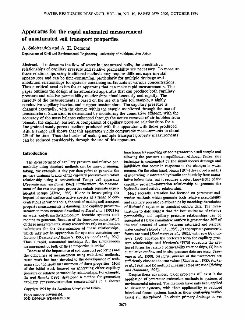
WATER RESOURCES RESEARCH, VOL. 30, NO. 10, PAGES 2679-2690, OCTOBER 1994
Apparatus for the rapid automated measurement of unsaturated soil transport properties A. Salehzadeh and A. H. Demond
Department of Civil and Environmental Engineering, University of Michigan, Ann Arbor
Abstract. To describe the flow of water in unsaturated soils, the constitutive relationships of capillary pressure and relative permeability are necessary. To measure these relationships using traditional methods may require different experimental apparatuses and can be time-consuming, particularly for multiple drainage and imbibition relationships for systems containing surfactants at various concentrations. Thus a critical need exists for an apparatus that can make rapid measurements. This paper outlines the design of an automated apparatus that can produce both capillary pressure and relative permeability relationships simultaneously and rapidly. The rapidity of the measurements is based on the use of a thin soil sample, a highly conductive capillary barrier, and stripper tensiometers. The capillary pressure is changed externally, with the change within the sample monitored through the use of tensiometers. Saturation is determined by monitoring the cumulative effluent, with the accuracy of the mass balance enhanced through the active removal of air bubbles from beneath the capillary barrier. A comparison of capillary pressure relationships for a fine-grained sandy porous medium produced with this apparatus with those produced with a Tempe cell shows that this apparatus yields comparable measurements in about 2% of the time. Thus the burden of making multiple transport property measurements can be reduced considerably through the use of this apparatus.
Introduction
The measurement of capillary pressure and relative per- meability using standard methods can be time-consuming, taking, for example, a day per data point to generate the primary drainage branch of the capillary pressure-saturation relationship using a conventional Tempe cell apparatus [Reginato and van Bavel, 1962]. Furthermore, the measure- ment of the two transport properties entails separate exper- imental setups [Klute, 1986]. If one is investigating the impact of several surface-active species at a range of con- centrations in various soils, the task of making soil transport property measurements is daunting. The capillary pressure- saturation measurements described by Desai et al. [1992] for air-water-cetyltrimethylammonium bromide systems took months to generate. Because of the time-consuming nature of these measurements, many researchers rely on estimation techniques for the determination of these relationships, which may not be appropriate for systems containing sur- factants [Demond and Roberts, 1993; Demond et al., 1994]. Thus a rapid, automated technique for the simultaneous measurement of both of these properties is critical.
Because of the importance of soil transport properties and the difficulties of measurement using traditional methods, much work has been devoted to the development of tech- niques for the rapid measurement of these properties. Most of the initial work focused on generating either capillary pressure or relative permeability relationships. For example, Su and Brooks [1980] developed a method for generating capillary pressure-saturation measurements in a shorter Copyfight 1994 by the American Geophysical Union.
Paper number 94WR01495. 0043-13 97/94/94 WR-01495 $05.00
time frame by removing or adding water to a soil sample and allowing the pressure to equilibrate. Although faster, this technique is confounded by the simultaneous drainage and imbibition that occur in response to the changes in water content. On the other hand, Ahuja [ 1974] developed a means of generating unsaturated hydraulic conductivity from cumu- lative inflow data, but it requires a priori knowledge of the capillary pressure-saturation relationship to generate the hydraulic conductivity relationship.
More recently, attention has focused on parameter esti- mation methods which generate both relative permeability and capillary pressure relationships by matching the solution of Richards' equation to transient outflow data. The inves- tigations to date suggest that the best estimates of relative permeability and capillary pressure relationships can be generated if (1) the cumulative outflow is greater than 50% of the total amount of water between saturated and residual water contents [Kool et al., 1985], (2) appropriate parametric forms are used [Zachmann et al., 1982], with van Genuch- ten's [1980] equation the preferred form for capillary pres- sure relationships and Mualem's [1976] equations the pre- ferred forms for relative permeability relationships, (3) both cumulative outflow and in situ pressure data are used [Toor- man et al., 1990], (4) initial guesses of the parameters are sufficiently close to the true values [Kool et al., 1985; Parker et al., 1985], and (5) multiple pressure steps are used [Eching and Hopmarts, 1993].
Despite these advances, major problems still exist in the application of parameter estimation methods to systems of environmental interest. The methods have only been applied to air-water systems, with their applicability to reduced interfacial forces systems (such as those containing surfac- tants) still unexplored. To obtain primary drainage curves
2679
2680 SALEHZADEH AND DEMOND: APPARATUS FOR RAPID AUTOMATED MEASUREMENT
[_ z2 'i
tensiometers
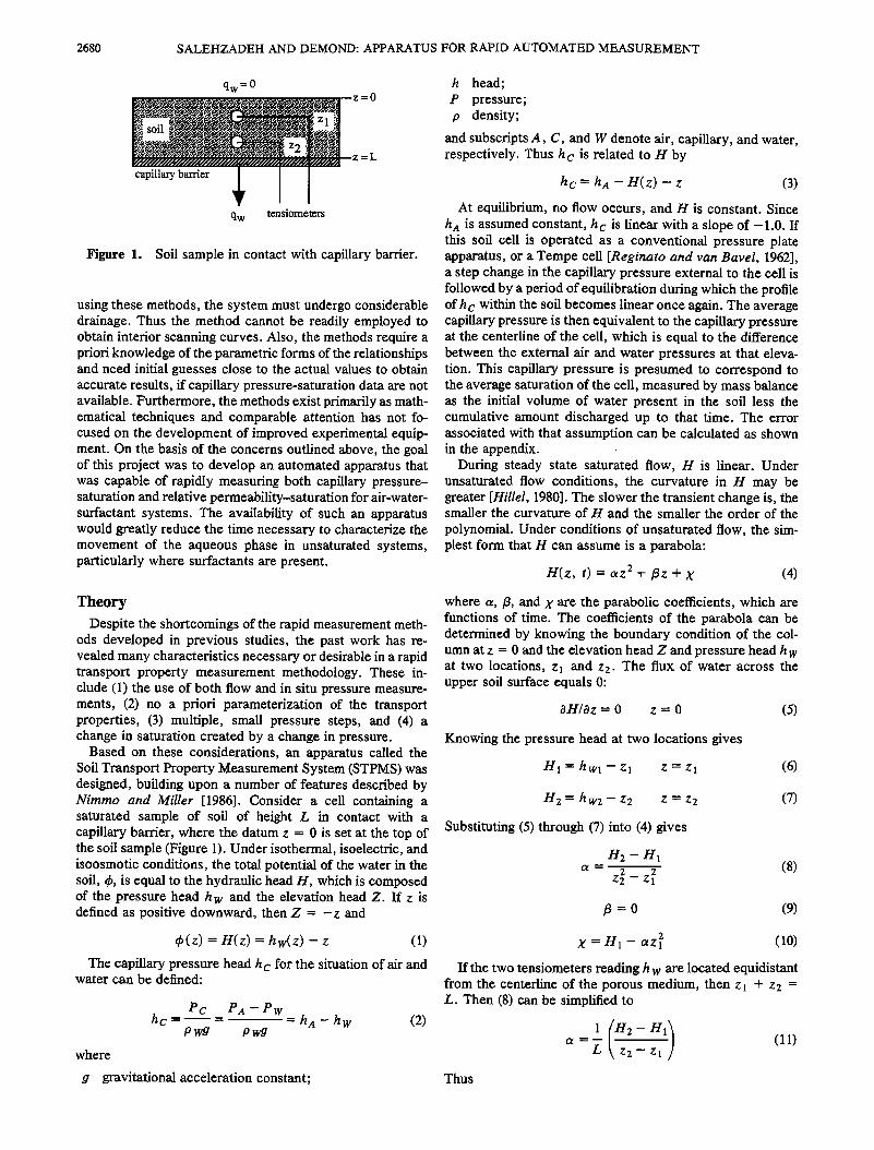
Figure 1. Soil sample in contact with capillary barrier.
using these methods, the system must undergo considerable drainage. Thus the method cannot be readily employed to obtain interior scanning curves. Also, the methods require a priori knowledge of the parametric forms of the relationships and need initial guesses close to the actual values to obtain accurate results, if capillary pressure-saturation data are not available. Furthermore, the methods exist primarily as math- ematical techniques and comparable attention has not fo- cused on the development of improved experimental equip- ment. On the basis of the concerns outlined above, the goal of this project was to develop an automated apparatus that was capable of rapidly measuring both capillary pressure- saturation and relative permeability-saturation for air-water- suffactant systems. The availability of such an apparatus would greatly reduce the time necessary to characterize the movement of the aqueous phase in unsaturated systems, particularly where suffactants are present.
h head; P pressure; p density;
and subscripts A, C, and W denote air, capillary, and water, respectively. Thus h c is related to H by
hc = hA - H(z) - z (3)
At equilibrium, no flow occurs, and H is constant. Since h A is assumed constant, h c is linear with a slope of -1.0. If this soil cell is operated as a conventional pressure plate apparatus, or a Tempe cell [Reginato and van Bayel, 1962], a step change in the capillary pressure external to the cell is followed by a period of equilibration during which the profile of h c within the soil becomes linear once again. The average capillary pressure is then equivalent to the capillary pressure at the centerline of the cell, which is equal to the difference between the external air and water pressures at that eleva- tion. This capillary pressure is presumed to correspond to the average saturation of the cell, measured by mass balance as the initial volume of water present in the soil less the cumulative amount discharged up to that time. The error associated with that assumption can be calculated as shown in the appendix. .
During steady state saturated flow, H is linear. Under unsaturated flow conditions, the curvature in H may be greater [Hillel, 1980]. The slower the transient change is, the smaller the curvature of H and the smaller the order of the
polynomial. Under conditions of unsaturated flow, the sim- plest form that H can assume is a parabola:
H( z, t) = az 2 + [3z + X (4)
Theory Despite the shortcomings of the rapid measurement meth-
ods developed in previous studies, the past work has re- vealed many characteristics necessary or desirable in a rapid transport property measurement methodology. These in- clude (1) the use of both flow and in situ pressure measure- ments, (2) no a priori parameterization of the transport properties, (3) multiple, small pressure steps, and (4) a change in saturation created by a change in pressure.
Based on these considerations, an apparatus called the Soil Transport Property Measurement System (STPMS) was designed, building upon a number of features described by Nimmo and Miller [1986]. Consider a cell containing a saturated sample of soil of height L in contact with a capillary barrier, where the datum z = 0 is set at the top of the soil sample (Figure 1). Under isothermal, isoelectric, and isoosmotic conditions, the total potential of the water in the soft, qb, is equal to the hydraulic head H, which is composed of the pressure head h w and the elevation head Z. If z is defined as positive downward, then Z = -z and
•P(z) = H(z) = hw(z) - z (1)
The capillary pressure head h c for the situation of air and water can be defined:
Pc PA--Pw hc -= • = = hA - h w (2)
P wg P wg
where
where a,/3, and X are the parabolic coefficients, which are functions of time. The coefficients of the parabola can be determined by knowing the boundary condition of the col- umn at z = 0 and the elevation head Z and pressure head h w at two locations, z! and z2. The flux of water across the upper soil surface equals 0:
OH/Oz = 0 z = 0 (5)
Knowing the pressure head at two locations gives
H1 = hwl - zl z = zl (6)
H2 = h w2- z2 z = z2 (7)
Substituting (5) through (7) into (4) gives
H2 - Hi
a = z2 2 _ z2 (8) 1
(9)
X = Hi- az• 2 (10)
If the two tensiometers reading h w are located equidistant from the centerline of the porous medium, then z l + z2 = L. Then (8) can be simplified to
a =• _•. (11) gravitational acceleration constant; Thus

SALEHZADEH AND DEMOND: APPARATUS FOR RAPID AUTOMATED MEASUREMENT 2681
H(z) = hw(z)- z = az 2 + X (12)
where a and X are given by (11) and (10), respectively. Since H can be calculated from (12) and hA is a known
constant set by the experimental protocol, the capillary pressure head profile can be calculated using (3). Once the capillary pressure head profile is known, the average capil- lary pressure can be calculated:
Pc(avg)--- 1/L Pc dz = PA -- + 2 + X (13)
This corresponds to the average saturation of the cell, measured by mass balance as initial volume of water present in the soil less the cumulative amount discharged up to that time, with the error as shown in the appendix.
Relative permeability kr• can be calculated from Darcy's law:
qw = -krwKs^T OH/Oz (14)
•2omputel.• Pressure regulation system
I I I I
' I I -:
I I I -: Computer h'--!-- + -- L - -- __
:
Pressure transducers
and signal amplification
Flow monitoring system
I !
I
t ' I I I I
•___
Figure 2. Schematic of the STPMS. Solid lines show liquid tubing, dashed lines show electrical cables, and dotted lines show air tubing.
where
q w specific discharge of water; krw relative permeability, defined as Kw/Ks^T, where
Kw = unsaturated hydraulic conductivity; Ks^•r saturated hydraulic conductivity,
if qw and OH/Oz are known. However, the only point at which qw is known is at z = L, at the soil-capillary barrier interface. Here,
qw = d(Q/A)/dt (15)
where Q is the cumulative volume of outflow, and A is the cross-sectional area of soil sample perpendicular to flow. Thus the derivative of H must also be evaluated at z = L:
OH = [2z]
L
or, substituting in the expression for a given by (11),
OH
(16)
(17)
Consequently,
1 d(Q/A)/dt
krw = -• KSAT[(H2_ H1)/(Z 2 _ Zl)] (18) 'ro relate the relative permeability obtained using (18) to the appropriate saturation, the saturation at z = L must be determined. This saturation can be obtained from the knowl- edge of the capillary pressure head at z = L, obtained from (3) and (12), for the same point in time as the saturation measurement, and the capillary pressure-saturation relation- ship.
Methods and Materials
Apparatus Design
The STPMS is shown schematically in Figure 2. The major components of the apparatus are (1) a flow cell, (2) a pressure measurement system to monitor the capillary pres-
sure in the soil, (3) a pressure regulation system to set the capillary pressure external to the flow cell, (4) a means of monitoring cumulative outflow as a function of time, and (5) a computer control center to operate the apparatus, and to collect and process the collected data.
The centerpiece of the apparatus is the flow cell, con- structed of 304 stainless steel. The height is 1.67 cm; this dimension was minimized to reduce saturation differences
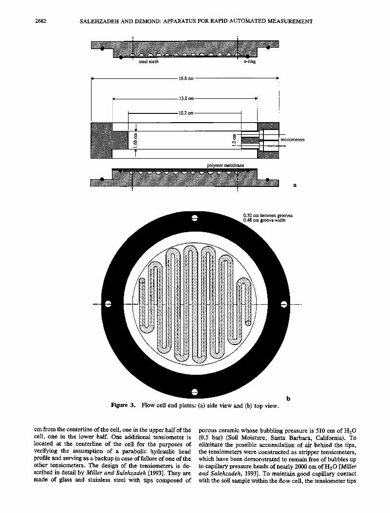
along the soil sample and to aid in the rapid response of the system. The inner diameter is 10 cm, a dimension selected so that the outflow would be sufficient to enable the monitoring of changes in saturation of under 0.5%. Figures 3a and'•3b show the end plates of the flow cell. In both end plates, a two-layer stainless steel mesh (120/am and 5 tzm meshes) (SWM-SW, Martin Kurz, Mineola, New York) is inlaid (Figure 3a). In the top end plate, this screen serves to confine the soil and to prevent soil loss during upflow. In the bottom end plate, this screen serves as a support for the capillary barber, a 195-/am-thick polymer membrane, having a bub- bling pressure of 1125 cm of H20 (16 psi) and a conductivity of 1.0 x 10 -3 cm/s (Gelman, Ann Arbor, Michigan). Both end plates are grooved to allow for bubble scavenging and the efficient distribution and collection of fluids (Figure 3b). Prior to its circulation beneath the capillary barrier;, water is deaerated by passing it through a vacuum stripper which operates on a similar principle as the stripper tensiometers described by Miller and Salehzadeh [1993]. The vacuum stripper consists of a glass tube containing thin-wall Teflon tubing closed at one end. The Teflon tubing is sufficiently permeable that when a vacuum is applied to it, air diffuses into it and is removed. Losses of water into the tubing are minimized by the maintenance of a high humidity within it. Since no air is accumulating behind the capillary barrier, no displacement of water exterior to the soil occurs, resulting in greater precision of the saturation determination by mass balance. In addition, no air bubbles interfere with the conductivity of the capillary barrie3, thus enhancing the reliability of the apparatus.
The tensiometers for measuring the capillary pressure within the porous medium have external diameters of 0.48 cm and internal diameters of 0.32 cm. They are located 0.5
2682 SALEHZADEH AND DEMOND: APPARATUS FOR RAPID AUTOMATED MEASUREMENT
I
steel mesh o-ring
16.8 cm
10.2 cm
tensiometers
polymer membrane
I ,
0.32 cm between grooves 0.48 cm groove width
Figure 3. Flow cell end plates: (a) side view and (b) top view.
cm from the centerline of the cell, one in the upper half of the cell, one in the lower half. One additional tensiometer is located at the centerline of the cell for the purposes of verifying the assumption of a parabolic hydraulic head profile and serving as a backup in case of failure of one of the other tensiometers. The design of the tensiometers is de- scribed in detail by Miller and Salehzadeh [1993]. They are made of glass and stainless steel with tips composed of
porous ceramic whose bubbling pressure is 510 cm of H20 (0.5 bar) (Soil Moisture, Santa Barbara, California). To eliminate the possible accumulation of air behind the tips, the tensiometers were constructed as stripper tensiometers, which have been demonstrated to remain free of bubbles up to capillary pressure heads of nearly 2000 cm of H20 [Miller and Salehzadeh, 1993]. To maintain good capillary contact with the soil sample within the flow cell, the tensiometer tips

SALEHZADEH AND DEMOND: APPARATUS FOR RAPID AUTOMATED MEASUREMENT 2683
flow controller
i •! solenoid i! t-b, • • regulator ambient air IEEEt valve
constant differential i:, ................................................... ? ........................................................................ !il la'l•ratoryi • laboratory
pressure regulator
metering laboratory air valve
filling (imbibiti0n)
gas cylinder
pressure transducer'
.................. •"'"'i"•'"•r.atory flow ce!l
Figure 4. Systems for pressure regulation and flow monitoring.
are covered with a thin layer of clay-sized silica. The tensiometers are connected to low displacement semicon- ductor pressure transducers whose full pressure range are either 352 or 1055 cm of H20 (5 or 15 pounds per square inch (psi)) (models SCX05DN or SCX15DN, SenSym, Sunny- vale, California), depending on whether Pw or differences in P w are being measured. The transducers' signals are ampli- fied and conditioned and then sent to the computer for processing and storage.
The system for controlling the capillary pressure is shown schematically in Figure 4. The STPMS operates as a biased- pressure apparatus. The soil air is maintained at a constant elevated pressure using a single-stage regulator (model 10, Fairchild, Winston-Salem, North Carolina) connected to the laboratory's compressed air lines, while the aqueous phase pressure is varied between the soil air pressure and atmo- spheric pressure. The pressure in the aqueous phase outside the cell is determined by the level of liquid and the air pressure in the aqueous phase reservoir, designated as the constant head tube (CHT). The air pressure is regulated by the pressure in a gas cylinder in series with the CHT. During drainage, the air pressure slowly decreases via the slow bleeding of air from the gas cylinder. The rate of bleeding is controlled by a constant differential flow controller (model SD63, Moore, Spring House, Pennsylvania), set to provide a constant pressure drop of 211 cm of H20 (3 psi) across a metering needle valve, and by the resistance provided by the needle valve, which can be adjusted manually .to obtain the desired bleeding rate for the particular pressure drop. The apparatus can switch between drainage and imbibition through two, two-way solenoid valves controlled through the computer. During imbibition, the aqueous phase pres- sure increases by slowly filling the gas cylinder. This is accomplished by a parallel set up of another metering needle valve and constant differential flow controller, connected to a single-stage regulator (model 10, Fairchild, Winston- Salem, North Carolina) regulating the pressure from the laboratory's compressed air lines. By setting the rate at which the gas cylinder empties or fills, one can control the rate at which the porous medium drains or imbibes.
Two electronically controlled flow tubes, having an inte- rior diameter of 1 cm, regulate the flow into and out of the
flow cell (Figure 4). The first tube, the CHT, maintains a constant head. The second tube monitors the cumulative amount of liquid that has exited or entered the flow cell up to any given time; this tube is referred to as the cumulative flow tube (CFT). The movement of liquid between the two tubes is controlled by a pressure transducer and a two-way sole- noid valve. During drainage the aqueous phase exits the flow cell and enters the CHT. The increase in head is sensed by a pressure transducer, which causes the solenoid valve be- tween the CHT and the CFT to open and the excess liquid to enter the CFT. During imbibition, the opposite occurs: a decrease in height in the CHT stemming from inflow into the flow cell opens the solenoid valve allowing liquid to exit the CFT. To maintain a high degree of accuracy in the sensing of the fluid heights, the pressure transducer for the CHT (model SCX05DN, SenSym, Sunnyvale, California) is operated in a differential mode, measuring the difference in the pressure between the head space in the top of the tube and the pressure beneath the water column. The full span of the pressure transducer is set to about 70 cm of H 20 so that it is sufficiently sensitive that changes in head of 0.2 cm of H20 trigger the solenoid valve. The pressure transducer associ- ated with the CFT measures the amount of liquid in that tube as a function of time. This pressure transducer (model DP15-30, Validyne, Northridge, California) has a full span of 88 cm of H20, more than adequate to handle the entire cumulative outflow. To ensure the rapid replacement or loss of liquid from the CHT, the difference in pressures between the two flow tubes is maintained at 211 cm of H2 ̧ using adjustable bias pressure regulators (model 14, Fairchild, Winston-Salem, North Carolina), despite the fact that the absolute pressures in the tubes are changing.
The computer serves as a control center, and as a data acquisition and processing unit. As a control center, the computer allows the user to select either a transient mode or step (Tempe cell) mode of operation and to specify items such as type of relationship to be measured (drainage versus imbibition), and the capillary pressures at which switches between drainage and imbibition should occur. It also mon- itors the functioning of the apparatus and alerts the user to problems such as an overflowing CFT. As a data acquisition unit, the computer accumulates output from five pressure

2684 SALEHZADEH AND DEMOND: APPARATUS FOR RAPID AUTOMATED MEASUREMENT
transducers, monitoring the following: (1) the capillary pres- sure at z•, located 0.5 cm above the centerline of the flow cell, (2) the difference between the aqueous phase pressures at z• and at z2, located 0.5 cm below the centerline of the cell, (3) the capillary pressure at the centerline of the flow cell, (4) the pressure in the aqueous phase external to the flow cell (set by the pressure in the CHT), and (5) the pressure in the CFT. The computer reads the signals coming from these sources every 5 s. To cut down on the electronic noise and the amount of data for subsequent manipulation and display, they can be averaged over a particular time interval designated by the user.
Operation
The STPMS can be run in both a transient mode and a step mode. In the transient mode, the transport relationships are determined from the accumulated data using (1)-(18). The capillary pressures at various locations in the soil are known from the information provided by the pressure transducers. H is determined from the measured pressures and the elevations relative to the datum. Then, the parameters to describe the profile of H are calculated using (10)-(12), and the average capillary pressure is calculated using (13) at each point in time. To calculate the corresponding saturation, the computer subtracts the reading in the CFT corresponding to the same point in time from the reference reading corre- sponding to S w = 1.0 to determine the quantity of!iquid lost or gained from the flow cell. Relative permeability is deter- mined using (18). To generate q w, a polynomial is fit to the measurements of Q, and the derivative is calculated. The corresponding saturation is the saturation at z = L, which is obtained from the value of the capillary pressure at z = L and the capillary pressure-saturation relationship.
in the step mode, the apparatus functions as an automated Tempe cell. A particular pressure in the aqueous phase is held and the outflow is monitored until it effectively ceases, after which the pressure in the aqueous phase is changed again. Since the apparatus was designed to produce a smooth succession of pressures, the maintenance of a par- ticular capillary pressure is accomplished by alternating rapidly between bleeding and filling modes so that the air pressure in the gas cylinder is maintained -_-0.2 cm of H20. The rate of accumulation in the CFT tube is monitored, and when the flow is less than the noise level of about -_-0.01
cm3/min, the aqueous phase pressure is changed by an amount specified by the user.
Experimental Media
The materials used in the measurements reported here are similar to those described by Desai et al. [1992] and Demond et al. [1994], where capillary pressure-saturation relation- ships were measured for surfactant systems using a modified Tempe cell. The porous medium was F-65 silica (U.S. Silica, Berkeley Springs, West Virginia) with a particle size range of 106-425 /xm. The si!ica was cleaned by washing several times with 0.1 N HC1 followed by several washes with 15% hydrogen peroxide at a pH of about 4 to remove metal ions and organic matter. The water was ultrapure, obtained by passing deionized, distilled water through Milli-Q cartridge filters (Millipore, Bedford, Massachusetts). Most of the measurements reported here utilized air and water only. In those measurements in which a surfactant was used, the surface-active compound was octanoic acid, purchased as a
salt (CH3(CH2)6CO2Na). The purity of the octanoic acid salt was 99% as purchased (Aldrich Chemical, Milwaukee, Wis- consin) and the chemical was used as received. Solutions of various concentrations were prepared by serial dilution, the pH of each was adjusted to 6.5 using HC1, and the surface tensions were measured using a Du Nouy tensiometer (Kruss USA, Charlotte, North Carolina).
The flow cell was packed wet on a vibrating table to a consistent porosity of 0.330 +- 0.002 and a saturated hydrau- lic conductivity of 0.010 +__ 0.002 cm/s. The core was then flooded with the aqueous phase. It was pumped through the cell at a rate of about 1.5 cm3/s until the cell was saturated, as determined by the attainment of a maximum hydraulic conductivity. In the measurements where a surfactant solu- tion was used as the aqueous phase, the pumping continued until the infiuent and effluent octanoic acid concentrations
were the same, as indicated by surface tension measure- ments. To ensure that the system was at equilibrium, several additional pore volumes were pumped through the cell. The in situ pressure measurements obtained upon full saturation were used to calculate the saturated hydraulic conductivity. After the cell was saturated, the air and aqueous phases were then pressurized to the same pressure, generally 352 cm of H20. Next, the pressure transducers were calibrated using a mercury manometer.
To start the primary drainage process in both the transient and step modes, the computer was set to the drainage mode. This caused the drainage solenoid valve to open so that air started bleeding from the gas cylinder controlling the pres- sure in the CHT. In the transient mode, the rate of bleeding was set by adjusting the metering needle valve until the rate of change of pressure was about 1 cm/min which, based on experience, was optimum for the systems examined here. In the step mode, the bleeding was faster, about 5 cm/min (to approximate a step change in pressure) until an increase in capillary pressure of 5-10 cm H20 was achieved. Then, the system started alternating between the bleeding and filling modes to maintain that capillary pressure. The process of increasing the capillary pressure continued until the accu- mulation in height in the CFT was less than 0.2 cm for an increase in capillary pressure of 20 cm H20.
At the conclusion of the drainage cycle, the computer was set to the imbibition mode. This switched the solenoid valves
so that air entered the gas cylinder from the laboratory's pressurized air lines, thus increasing the pressure in the cylinder and in the head space above the aqueous phase in the CHT. For some runs, the computer was programmed to reverse direction automatically when a predetermined cap- illary pressure was reached. This allowed the generation of repeated drainage and imbibition cycles over time.
For comparison, measurements were also obtained using a Tempe cell (Soil Moisture, Santa Barbara, California). The materials were prepared in the same manner as with the STPMS measurements. The method of controlling the pres- sure in the air and aqueous phases and other details of the experimental protocol of these measurements are described by Desai et al. [1992] and Demond et al. [1994].
Results and Discussion
The analysis of the transient data depended on the descrip- tion of the hydraulic head profile as a parabola. To evaluate the validity of this assumption, the hydraulic head at the

SALEHZADEH AND DEMOND: APPARATUS FOR RAPID AUTOMATED MEASUREMENT 2685
70
• 40
•, so
• 20 •o
o
o 0.2
computed measured
0.4 0.6 0.8
Saturation, cm3/cm 3
0.2
o
, ,,
o experimental points I ,, fitted function
o o
' ----"'•'• I I I I l, ' ' ' I , , •
0.2 0.4 0.6 0.8
Saturation, cm3/cm 3 0 1
Figure 5. Comparison of calculated and measured hydrau- lic heads at centerline of flow ceil.
centerline of the cell was calculated based on (10)-(12), and compared with the hydraulic head derived from the reading of the tensiometer located at the centerline. The comparison of calculated and measured hydraulic heads shown in Figure 5 suggests that a parabola adequately describes the depen- dence of H on z over a wide range of saturations for the experimental conditions employed here.
To demonstrate the ability of the apparatus to generate capillary pressure and relative permeability data quickly, a series of repeated drainage and imbibition measurements was performed. Figure 6 shows the result of an experiment involving the measurement of four curves of the capillary pressure-saturation relationship performed over the course of 12 hours. Figure 7 shows the relative permeability rela- tionship corresponding to the primary drainage curve, cal- culated from information produced in the same experiment as in Figure 6. Near full saturation, considerable noise exists in the data. At high saturations, the electronic noise is comparable to the small magnitude of the pressure head difference along the soil column, on the order of 0.1 cm of H20. As the soil drains, the difference becomes larger and the signal to noise ratio improves. To minimize the impact of
120
¸ lOO
• 60
40
20
1) primary drainage 2) spontaneous imbibition 3) secondary drainage 4) interior scanning imbibition
0 0.2 0.4 0.6 0.8 1
Saturation, cm3/cm 3
Figure 6. Capillary pressure-saturation relationships gen- erated with the STPMS for air-water system over a 12-hour period.
Figure 7. Primary drainage relative permeability-satura- tion relationship generated with the STPMS for air-water system. Fitted function is given by (19), with a = 0.023, b = 0.159, and c = 0.332.
the noise in the range of 0.8 < $ < 1.0 (where S is the saturation of the aqueous phase) a function was fitted to the data, preferentially weighting the points at lower saturations. The functional form selected,
krw = S •[1 - (1 - S I/b) b] c (19)
where S e is the effective saturation (defined as (S - $r)[ (1 - St), S r is the residual saturation) and a, b, and c are the empirical constants found through regression, was based on the equation given by van Genuchten [ 1980] for Mualem's [1976] relative permeability model with the capillary pres- sure data described by van Genuchten's capillary pressure relationship. Fitting (19) to the data using absolute error as the loss function yielded the values of 0.023, 0.159, and 0.332, for a, b, and c, respectively, with the goodness of fit illustrated in Figure 7.
To evaluate the performance of the STPMS, a series of measurements were made under different conditions. The emphasis here was to demonstrate the apparatus's ability to produce capillary pressure measurements, since a number of reasonable methods exist for the calculation of relative permeability of the aqueous phase from capillary pressure measurements [e.g., Mualem, 1976], even in systems with reduced surface tensions [Dernond and Roberts, 1993]. Thus the ability of the STPMS to produce accurate capillary pressure measurements was deemed more critical.
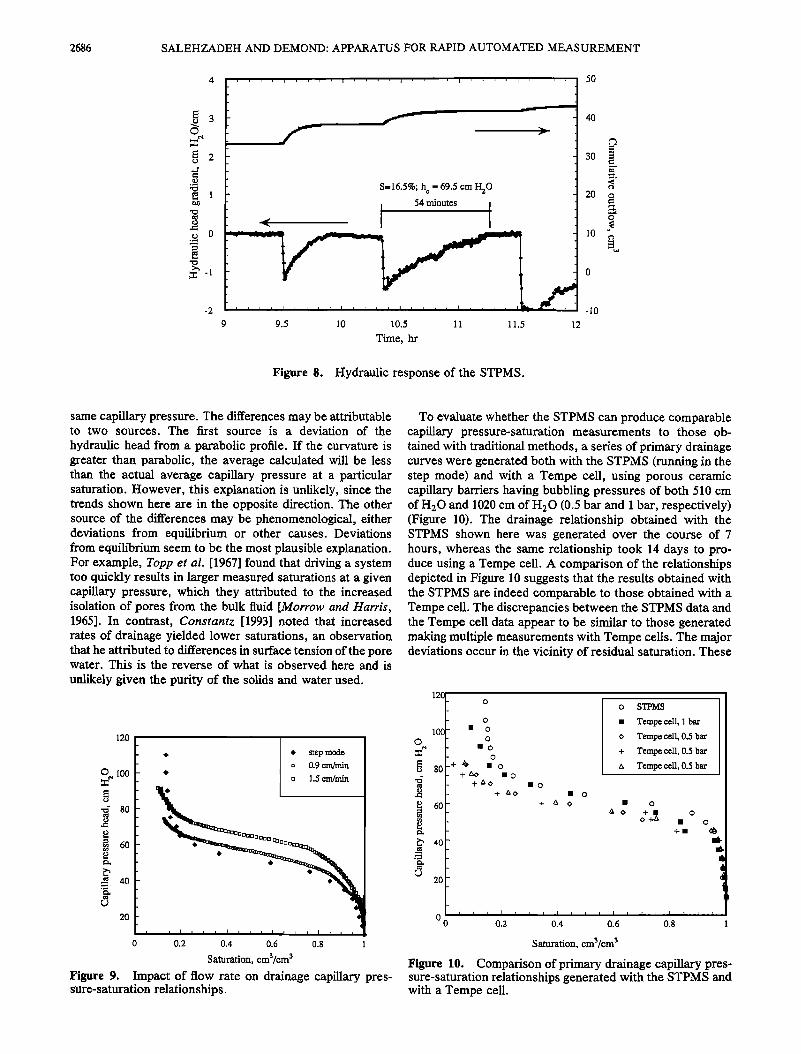
The key to the apparatus's rapidity is the reduction in response time resulting from the thinness of the soil sample and the high conductivity of the capillary barrier. Figure 8 shows the hydraulic response of the system to a series of step increases in capillary pressure. These data illustrate that the response time is on the order of 50 min at 16% saturation, considerably shorter than the response time for a conven- tional Tempe cell, which for a comparable soil and saturation is on the order of a day [Dernond and Roberts, 1991]. Despite the system's rapid response time, it may, neverthe- less, be possible to drive the system sufficiently quickly that the results deviate from those obtained under equilibrium conditions. A series of measurements was made using suc- cessively faster rates of drainage. Figure 9 shows that the saturations obtained at a drainage rate of 1.5 cm/min are generally higher than those obtained at lower rates at the
2686 SALEHZADEH AND DEMOND: APPARATUS FOR RAPID AUTOMATED MEASUREMENT
S=16.5%; h e = 69.5 cm H20
i 54 minutes.
9 9.5 10 10.5 11 11.5 !2
Time, hr
50
40
30 E
20 o
10 '
-10
Figure 8. Hydraulic response of the STPMS.
same capillary pressure. The differences may be attributable to two sources. The first source is a deviation of the
hydraulic head from a parabolic profile. If the curvature is greater than parabolic, the average calculated will be less than the actual average capillary pressure at a particular saturation. However, this explanation is unlikely, since the trends shown here are in the opposite direction. The other source of the differences may be phenomenologica!, either deviations from equilibrium or other causes. Deviations from equilibrium seem to be the most plausible explanation. For example, Toppet al. [1967] found that driving a system too quickly results in larger measured saturations at a given capillary pressure, which they attributed to the increased isolation of pores from the bulk fluid [Morrow and Harris, 1965]. In contrast, Constantz [1993] noted that increased rates of drainage yielded lower saturations, an observation that he attributed to differences in surface tension of the pore water. This is the reverse of what is observed here and is
unlikely given the purity of the solids and water used.
120
•o
6O
4O
2O
step mode 0.9 cm/min
1.5 cm/min
0 0.2 0.4 0.6 0.8 1
Saturation, cm3/cm 3
Figure 9. Impact of flow rate on drainage capillary pres- sure-saturation relationships.
To evaluate whether the STPMS can produce comparable capillary pressure-saturation measurements to those ob- tained with traditional methods, a series of primary drainage curves were generated both with the STPMS (running in the step mode) and with a Tempe cell, using porous ceramic capillary barriers having bubbling pressures of both 510 cm of H20 and 1020 cm of H20 (0.5 bar and 1 bar, respectively) (Figure 10). The drainage relationship obtained with the STPMS shown here was generated over the course of 7 hours, whereas the same relationship took 14 days to pro- duce using a Tempe cell. A comparison of the relationships depicted in Figure ! 0 suggests that the results obtained with the STPMS are indeed comparable to those obtained with a Tempe cell. The discrepancies between the STPMS data and the Tempe cell data appear to be similar to those generated making multiple measurements with Tempe cells. The major deviations occur in the vicinity of residual saturation. These
,2.r [] % I [] Tempeo•n, • • I I '; I + T empe ce!!' 0.5 bar I
E 6
• no
D 2
0 0 0.2 0.4 0.6 0.8 1
Saturation, cm¾cm 3
Figure 10. Comparison of primary drainage capillary pres- sure-saturation relationships generated with the STPMS and with a Tempe cell.

SALEHZADEH AND DEMOND: APPARATUS FOR RAPID AUTOMATED MEASUREMENT 2687
differences may be attributed to air bubbles which were observed to form beneath the capillary barrier in the Tempe cells containing the 510 cm of H20 capillary barriers. If air bubbles form in the cavity beneath the capillary barrier, some of the water discharged from the flow cell results from a desaturation of the flow cell itself, rather than from that of the soil. Since saturation is determined on the basis of
cumulative effluent, this additional discharge of water results in the recording of lower saturations than are actually the case. Because of the lack of any mechanism for the elimina- tion of these air bubbles in a Tempe cell, the determination of the saturation by measuring the amount of water dis- charged may, in fact, be less accurate in the case of conventional pressure plate apparatuses.
The original impetus for the development of the STPMS was the need to make measurements for systems containing surfactants. In such systems, soil transport relationships are a function of both aqueous phase saturation and surfactant concentration, consequently requiring additional measure- ments to characterize the correspondence between capillary pressure and saturation. Figure 11 shows primary drainage capillary pressure-saturation relationships for air-water sys- tems containing octanoic acid. Each curve took about 7-8 hours to produce. Figure 12 shows these relationships scaled by dividing the capillary pressure by the surface tension (in an application of Leverett's function [Leverett, 194!]) and by converting saturation to effective saturation. The fact that these drainage relationships scale satisfactorily provides affirmation that the STPMS can yield accurate capillary pressure-saturation relationships for air-water-surfactant systems.
Summary and Conclusions If one is investigating the impact of several surface-active
species at a range of concentrations in various soils, the task of making capillary pressure and relative permeability mea- surements using conventional methodology can be daunting. Thus the development of a rapid, automated technique for the simultaneous measurement of both of these properties is critical. In response to this need, a computer-controlled apparatus, called the Soil Transport Property Measurement System, has been developed that can measure both capillary
150 o " Octanoic Acid Surface Tension
,,,
0.0 M 70.5 dynes/cm
0.05 M 41.2 dynes/cm ,
0.075 M 32.1 dynes/cm
• o
o ,5 o
100 2a o
• 75 • 0.05 M o o • 50 a a o • o o
• - 0.075 M _
0 - , • • I I • , I •,•,,• I •, I I ,I I ' 0 0.2 0.4 0.6 0.8 1
Sa•aaon,
Fibre 11. Measurements of pdm• dr•n•e capi!l•y pressure-saturation relationships for •-water-octanoic acid systems.
• 7 8 6
3 •o 2
= 1
co 0
0.0 M
0.05 M
0.075 M
0 0.2 0.4 0.6 0.8 1
Effective saturation, cra3/crn 3
Figure 12. Scaled primary drainage capillary pressure- saturation relationships for air-water-octanoic acid systems.
pressure and relative permeability quickly. Due to the rapid- ity of its hydraulic response, it takes about 4-5 hours to complete an air-water drainage measurement for a fine- to medium-grained sandy porous medium in the apparatus's transient mode. It can also be programmed to run as an automated pressure cell, a mode which is somewhat slower than the transient means of operation but has the advantage of not needing in situ pressure data. A comparison of capillary pressure measurements made with the STPMS with those generated with a Tempe cell shows that the apparatus produces measurements that compare favorably with those obtained with a conventional pressure plate cell, in about 2% of the time. The STPMS was also able to produce capillary pressure relationships for air-water systems containing oc- tanoic acid in a similar time frame, with their reasonableness suggested by the satisfactory scaling of the relationships.
Appendix To generate a capillary pressure-saturation relationship,
corresponding values of saturation and capillary pressure must be determined. The STPMS gives an average value of saturation and a profile of capillary pressure within the soil, from which an average capillary pressure can be calculated using (13). The error in assuming that the average saturation corresponds to the average capillary pressure can be deter- mined as follows. The saturation within the soil S (where S is considered to be solely a function of P w which, in turn, is a function of z and t) can be expressed by expanding S around z = 0 using a Taylor series:
OS 1 02S 1 03S S(z) = So + • z + z 2 +3!oz
1 c34S
q' '-• 0'-• z4 q'''' (A1) where So = SIz=o and all the derivatives are evaluated at z=0.
By the chain rule, the first derivative is
OS/Oz = (dS/dPw)(OPw/OZ) (A2)
At z = 0, O H/az = 0, leading to the conclusion that c3Pw/c3Zlz= o = 1. Thus (A2) becomes

2688 SALEHZADEH AND DEMOND: APPARATUS FOR RAPID AUTOMATED MEASUREMENT
aS dS
Oz z-.o dPw The second derivative can be written
dS (• 102P _ ..___•_w (A3) S^vo •So+d-•w +60z 2 L2.•
oz 2 = • •;• o• I = Fzz 02Pw dS Oz 2 dP w
d2S [OPwt2 02Pw dS dV• \-7Fz I + '- Oz dP w
However, since OPw/OZ z=o = 1, (A4) becomes
d2S 02Pw dS = d'-• w+ Oz 2 dPw
02S
Oz 2 z=0
Similarly, for the third derivative,
03S 0 i d2S IcgPwl 2 02Pw dS)
(A4)
(A5)
OPw d2S 02P 3p w dS 0 w
+• dP• • (A6) Oz Oz 2 +dPw Oz 3 However, since oP•/ozlz=o = 1, (A6) simplifies to
O3S d3S d2S O2pw dS 03Pw Oz 3 =d'•w+3 2 t (A7) z=o dp2 w Oz dPw Oz 3
By the same process, the fouah derivative can be derived:
O4S d4S d3S 02Pw
øZ4 z=o a• + 6 a• oz 2
+ d• 3 Oz 2 ] + 4 OZ 3 I + d• O• 4 Inse•ing the expressions for the derivatives, (A3), (AS), (A7), and (AS), into (A1) and rea•an•ng yields
dS ( 1 O2P 1 O3P S(z)•SO+d• z+ Wz2+_ • 3 20z 2 60z 3 z
1 04Pw ) d2S (1 2 1 02P • 24 Oz 4 z4 +dP• •z +-• 3 20z 2 z
+ +- z4 + 3 6 d• z
102P d4S( 1 ) wg4+ 4 +4 az 2 dv• •z (•9) where • the derivatives •e evaluated at z = 0.
To obt•n the average saturation, (A9) is integrated over z = 0 to L and divided by L:
1 03Pw 24 OZ 3
L 3
w d2S 1 c32p _ ._..._ff.w t 120 az 4 L4 + d'-•ww + 8 Oz 2 L3
(1 fO2Pw• 2 1 O3Pw• ) d3S (1 + •-• • O'-•J + 30 •] '] L4 +d• : L3
+20 oz = z +d• 1• • (a10) If Pw were expressed as a Taylor series around z = 0, and then averaged over the interval z = 0 to L, then P wav6 would equal
1 OPw 1 O2P 3p w 1 O w = L+-•L 2 ••L 3 Pwavo Pwo +2 az 6 Oz 2 +24 Oz 3
1 O4Pw 120 az 4 L4 +... (All)
However, since OPw/OZ z=O = 1, the quantity PwAvo -- Pwo is identical to the coefficient for dS/dP w in (A10). Thus (A10) becomes
dS
SAVG --• So + d-•w (PwAvG - PwO)
d2S(: IO2Pw + d-7-• + • oz "--'-r •'
+(4•(O2PWl 2 1 OZ 2 I • 30 5 •']L4) d3S ( 1 I O2P
w
+d• • L3 +20 Oz 2 L4
+d• 1• • (•12) If the first two terms of (A12) described the relationship between S xv6 and P w•v6, the co•espondence between the two would be exact. The terms containing the higher-order derivatives express the e=or involved in making this as- sumption. Thus the second-order e•or is
(: d2S L2 1 O2P EO(2)•d• +8 Oz 2 L3
+ • Oz 2 ] • 30 •5'j L4 (A13) If the profile of the hydraulic head is parabolic, then accord- ing to (11) and (12),
w 2 H2- H1 (A14) oz • =• '•-Zl and the higher-order derivatives are equ• to zero.
Thus (A13) becomes

SALEHZADEH AND DEMOND: APPARATUS FOR RAPID AUTOMATED MEASUREMENT 2689
0.02
/ / ,' 1
• -• - •(.oo3) o.o / / .-' 'i ....
0.•5
0
0 -2 -4 -6 -8 -10
Hydraulic head gradient, cm H20/cm
Figure 13. Error in correspondence between average saturation, measured volumetrically, and average capillary pressure.
d2S 1 H 2 - H• 1 H2- H !
(A15)
The same analysis can be applied to a Tempe cell. Here, the profile of P w with respect to z is linear at equilibrium. Consequently, second- and higher-order derivatives are equal to zero, and the second-order error for a Tempe cell is
d2S L 2
EO(2) = dp2w 6 (A16) Figure 13 shows the error of assuming that S^va, mea-
sured volumetrically, corresponds to P w^vG for the STPMS undergoing drainage. The curves shown in Figure 13 are based on (A15) with L = 1.7 cm. The same curves can be used to obtain the error for a Tempe cell by looking at the values corresponding to a hydraulic head gradient of zero and adjusting for the differences in height of the soil sample. For example, the error for our Tempe cells (where L = 3.0 cm), corresponding to d2S/dp2w = 0.005 is 0.75%.
If the error associated with a Tempe cell is deemed acceptable, the STPMS can be operated with a hydraulic head gradient of up to about -3.5 cm of H20/cm, before this limit is exceeded. As the soil becomes drier, d2S/dp2w decreases, and a greater gradient is permissible. This infor- mation allows the user of the STPMS to tailor the drainage rate so that the error of correspondence between average saturation and average capillary pressure remains below the desired maximum.
Acknowledgments. Funding for the development of this appara- tus was provided by the Office of Research and Development, U.S. Environmental Protection Agency under grant R-819650 to the Great Lakes and Mid-Atlantic Hazardous Substance Research Cen- ter. Partial funding of the research activities of the Center was also provided by the State of Michigan Department of Natural Re- sources. The content of this publication does not necessarily repre- sent the views of either agency. The testing of the apparatus using
systems containing surfactknts was part of a research project funded by the Subsurface Science Program (Frank J. Wobber, Program Manager), Office of Health and Environmental Research, U.S. Department of Energy (grant DOE-FG02-89ER60820).
References
Ahuja, L. R., Unsaturated hydraulic conductivity from cumulative inflow data, Soil Sci. $oc. Am. Proc., 38, 695-699, 1974.
Constantz, J., Confirmation of rate-dependent behavior in water retention during drainage in nonswelling porous materials, Water Resour. Res., 29(4), 1331-1334, !993.
Demond, A. H., and P. V. Roberts, Effect of interfacial forces on two-phase capillary pressure-saturation relationships, Water Re- sour. Res., 27(3), 423-437, 1991.
Demond, A. H., and P. V. Roberts, Estimation of two-phase relative permeability relationships for organic liquid contami- nants, Water Resour. Res., 29(4), 1081-1090, !993.
Demond, A. H., F. N. Desai, and K. F. Hayes, Effect of cationic suffactants on organic liquid-water capillary pressure-saturation relationships, Water Resour. Res., 30(2), 333-342, 1994.
Desai, F. N., A. H. Demond, and K. F. Hayes, Influence of suffactant sorption on capillary pressure-saturation relationships, in Transport and Remediation of Subsurface Contaminants: Colloidal, Interfacial, and Surfactant Phenomena, edited by D. A. Sabatini and R. C. Knox, pp. 133-148, American Chemical Society, Washington, D.C., 1992.
Eching, S. O., and J. W. Hoproans, Optimization of hydraulic functions from transient outflow and soil water pressure data, Soil Sci. Soc. Am. J., 57(5), 1167-1175, 1993.
Hillel, D., Fundamentals of Soil Physics, p. 199, Academic, San Diego, Calif., 1980.
Klute, A. (Ed.), Physical and Mineralogical Methods in Methods of Soil Analysis, 2nd ed., American Society of Agronomy, Madison, Wis., 1986.
Kool, J. B., J. C. Parker, and M. T. van Genuchten, Determining soil hydraulic properties from one-step outflow experiments by parameter estimation, 1, Theory and numerical studies, Soil Sci. Soc. Am. J., 49, 1348-1354, !985.
Leverett, M. C., Capillary behavior in porous solids, Trans. Am. Inst. Min. Metall. Pet. Eng., 142, 152-169, 1941.
Miller, E. A., and A. Salehzadeh, "Stripper" for bubble-free tensiometry, Soil Sci. Soc. Am. J., 57(6), 1470-1473, 1993.
Morrow, N. R., and C. C. Harris, Capillary equilibrium in porous materials, Soc. Pet. Eng. J., 5(1), 15-24, 1965.
Mualem, Y., A new model for predicting the hydraulic conductivity

2690 SALEHZADEH AND DEMOND: APPARATUS FOR RAPID AUTOMATED MEASUREMENT
of unsaturated porous media, Water Resour. Res., •2(3), 513-522, 1976.
Nimmo, J. R., and E. E. Miller, The temperature dependence of isothermal moisture vs. potential characteristics of soils, Soil Sci. Soc. Am. J., 50(5), 1105-1113, 1986.
Parker, J. C., J. B. Kool, and M. T. van Genuchten, Determining soil hydraulic properties from one-step outflow experiments by parameter estimation, II, Experimental studies, Soil Sci. Soc. Am. J., 49, 1354--1359, 1985.
Reginato, R. J., and C. H. M. van Bavel, Pressure cell for soil cores, Soil Sci. Soc. Am. Proc., 26(1), 1-3, 1962.
Su, C., and R. H. Brooks, Water retention measurement for soils, J. Irrig. Drain. Div. Am. Soc. Civ. Eng., I06(iR2), 105-112, 1980.
Toorman, A. F., P. J. Wierenga, and R. G. Hills, Estimation of soil-water parameters from transient laboratory experiments, Agron. Abstr., 1990 220, 1990.
Topp, G. C., A. Klute, and D. B. Peters, Comparison of water
content-pressure head data obtained by equilibrium, steady-state, and unsteady-state methods, Soil Sci. Soc. Am. Proc., 31,312- 314, 1967.
van Genuchten, M. T., A closed form solution for predicting the hydraulic conductivity of unsaturated soils, Soil $ci. $oc. Am. J., 44, 892-898, 1980.
Zachmann, D. W., P. C. DuChateau, and A. Klute, Simultaneous approximation of water capacity and soil hydraulic conductivity by parameter identification, Soil Sci., 134, 157-163, 1982.
A. H. Demond and A. Salehzadeh, Department of Civil and Environmental Engineering, University of Michigan, Ann Arbor, MI 48109-2125.
(Received December 13, 1993; revised May 26, !994; accepted June 8, 1994.)
Copyright © 2022 FDOKUMEN