METHOD AND APPARATUS FOR CONTROLLING THE GAP ...
25
Note: Within nine months of the publication of the mention of the grant of the European patent in the European Patent Bulletin, any person may give notice to the European Patent Office of opposition to that patent, in accordance with the Implementing Regulations. Notice of opposition shall not be deemed to have been filed until the opposition fee has been paid. (Art. 99(1) European Patent Convention). Printed by Jouve, 75001 PARIS (FR) (19) EP 1 833 659 B1 TEPZZ_8¥¥659B_T (11) EP 1 833 659 B1 (12) EUROPEAN PATENT SPECIFICATION (45) Date of publication and mention of the grant of the patent: 20.09.2017 Bulletin 2017/38 (21) Application number: 05855841.2 (22) Date of filing: 29.12.2005 (51) Int Cl.: B29C 65/64 (2006.01) B23K 20/10 (2006.01) B29C 65/08 (2006.01) B06B 3/00 (2006.01) (86) International application number: PCT/US2005/047347 (87) International publication number: WO 2006/074031 (13.07.2006 Gazette 2006/28) (54) METHOD AND APPARATUS FOR CONTROLLING THE GAP BETWEEN THE HORN AND THE ANVIL OF AN ULTRASONIC WELDING SYSTEM VERFAHREN UND VORRICHTUNG ZUR STEUERUNG DES SPALTS ZWISCHEN HORN UND AMBOSS EINES ULTRASCHALLSCHWEISSSYSTEMS PROCEDE ET APPAREIL DE REGLAGE DE L’INTERVALLE SEPARANT LE CORNET DE L’ENCLUME D’UN SYSTEME DE SOUDAGE PAR ULTRASONS (84) Designated Contracting States: AT BE BG CH CY CZ DE DK EE ES FI FR GB GR HU IE IS IT LI LT LU LV MC NL PL PT RO SE SI SK TR (30) Priority: 03.01.2005 US 640979 P (43) Date of publication of application: 19.09.2007 Bulletin 2007/38 (73) Proprietor: 3M Innovative Properties Company St. Paul, MN 55133-3427 (US) (72) Inventors: • NAYAR, Satinder K. Saint Paul, Minnesota 55133-3427 (US) • FETTIG, Paul, M. Saint Paul, Minnesota 55133-3427 (US) • POCHARDT, Donald, L. Saint Paul, Minnesota 55133-3427 (US) • OBLAK, Donald, S. Saint Paul, Minnesota 55133-3427 (US) • MLINAR, John, R. Saint Paul, Minnesota 55133-3427 (US) (74) Representative: Vossius & Partner Patentanwälte Rechtsanwälte mbB Siebertstrasse 3 81675 München (DE) (56) References cited: EP-A- 0 689 930 US-A1- 2002 062 903 US-A1- 2003 057 259 US-B1- 6 508 641
-
Upload
khangminh22 -
Category
Documents
-
view
0 -
download
0
Transcript of METHOD AND APPARATUS FOR CONTROLLING THE GAP ...

Note: Within nine months of the publication of the mention of the grant of the European patent in the European PatentBulletin, any person may give notice to the European Patent Office of opposition to that patent, in accordance with theImplementing Regulations. Notice of opposition shall not be deemed to have been filed until the opposition fee has beenpaid. (Art. 99(1) European Patent Convention).
Printed by Jouve, 75001 PARIS (FR)
(19)E
P1
833
659
B1
TEPZZ_8¥¥659B_T(11) EP 1 833 659 B1
(12) EUROPEAN PATENT SPECIFICATION
(45) Date of publication and mention of the grant of the patent: 20.09.2017 Bulletin 2017/38
(21) Application number: 05855841.2
(22) Date of filing: 29.12.2005
(51) Int Cl.:B29C 65/64 (2006.01) B23K 20/10 (2006.01)
B29C 65/08 (2006.01) B06B 3/00 (2006.01)
(86) International application number: PCT/US2005/047347
(87) International publication number: WO 2006/074031 (13.07.2006 Gazette 2006/28)
(54) METHOD AND APPARATUS FOR CONTROLLING THE GAP BETWEEN THE HORN AND THE ANVIL OF AN ULTRASONIC WELDING SYSTEM
VERFAHREN UND VORRICHTUNG ZUR STEUERUNG DES SPALTS ZWISCHEN HORN UND AMBOSS EINES ULTRASCHALLSCHWEISSSYSTEMS
PROCEDE ET APPAREIL DE REGLAGE DE L’INTERVALLE SEPARANT LE CORNET DE L’ENCLUME D’UN SYSTEME DE SOUDAGE PAR ULTRASONS
(84) Designated Contracting States: AT BE BG CH CY CZ DE DK EE ES FI FR GB GR HU IE IS IT LI LT LU LV MC NL PL PT RO SE SI SK TR
(30) Priority: 03.01.2005 US 640979 P
(43) Date of publication of application: 19.09.2007 Bulletin 2007/38
(73) Proprietor: 3M Innovative Properties CompanySt. Paul, MN 55133-3427 (US)
(72) Inventors: • NAYAR, Satinder K.
Saint Paul, Minnesota 55133-3427 (US)
• FETTIG, Paul, M.Saint Paul, Minnesota 55133-3427 (US)
• POCHARDT, Donald, L.Saint Paul, Minnesota 55133-3427 (US)
• OBLAK, Donald, S.Saint Paul, Minnesota 55133-3427 (US)
• MLINAR, John, R.Saint Paul, Minnesota 55133-3427 (US)
(74) Representative: Vossius & Partner Patentanwälte Rechtsanwälte mbBSiebertstrasse 381675 München (DE)
(56) References cited: EP-A- 0 689 930 US-A1- 2002 062 903US-A1- 2003 057 259 US-B1- 6 508 641
EP 1 833 659 B1
2
5
10
15
20
25
30
35
40
45
50
55
Description
Field of the Invention
[0001] The present Invention relates to ultrasonicwelding, and more particularly to a system and devicefor adjusting the position of an ultrasonic welding horn inresponse to changing process conditions.
Background
[0002] In ultrasonic welding (sometimes referred to as"acoustic welding" or "sonic welding"), two parts to bejoined (typically thermoplastic parts) are placed proxi-mate a tool called an ultrasonic "horn" for delivering vi-bratory energy. These parts (or "workpieces") are con-strained between the horn and an anvil. Oftentimes, thehorn is positioned vertically above the workpiece and theanvil. The horn vibrates, typically at 20,000 Hz to 40,000Hz, transferring energy, typically in the form of frictionalheat, under pressure, to the parts. Due to the frictionalheat and pressure, a portion of at least one of the partssoftens or is melted, thus joining the parts.[0003] During the welding process, an alternating cur-rent (AC) signal is supplied to a horn stack, which in-cludes a converter, booster, and horn. The converter (al-so referred to as a "transducer") receives the AC signaland responds thereto by compressing and expanding ata frequency equal to that of the AC signal. Therefore,acoustic waves travel through the converter to the boost-er. As the acoustic wavefront propagates through thebooster, it is amplified, and is received by the horn. Fi-nally, the wavefront propagates through the horn, and isimparted upon the workpieces, thereby welding them to-gether, as previously described.[0004] Another type of ultrasonic welding is "continu-ous ultrasonic welding". This type of ultrasonic weldingis typically used for joining fabrics and films, or other"web" workpieces, which can be fed through the weldingapparatus in a generally continuous manner. In continu-ous welding, the ultrasonic horn is typically stationaryand the part to be welded is moved beneath it. One typeof continuous ultrasonic welding uses a rotationally fixedbar horn and a rotating anvil. The workpiece is pulledbetween the bar horn and the anvil. The horn typicallyextends longitudinally towards the workpiece and the vi-brations travel axially along the horn into the workpiece.In another type of continuous ultrasonic welding, the hornis a rotary type, which is cylindrical and rotates about alongitudinal axis. The input vibration is in the axial direc-tion of the horn and the output vibration is in the radialdirection of the horn. The horn is placed close to an anvil,which typically is also able to rotate so that the workpieceto be welded passes between the cylindrical surfaces ata linear velocity, which substantially equals the tangentialvelocity of the cylindrical surfaces. This type of ultrasonicwelding system is described in U.S. Pat. No: 5,976,316.[0005] EP 0 689 930 A discloses an apparatus and a
method for bonding at least two continuously moving sub-strate webs together. The apparatus comprises a rotat-able bonding roll which is located adjacent the substratewebs and configured to rotate about a bonding axis. Arotatable anvil roll has an anvil surface and is configuredto rotate about an anvil axis to press the substrate websagainst an outer peripheral bonding surface of the bond-ing roll thereby bonding the substrate webs together. Theanvil roll is pivotally connected to a pivotal support mech-anism which is configured to maintain the anvil surfacein a substantially parallel relationship with the bondingsurface. The pivotal support mechanism is configured toallow the anvil roll to pivot such that the anvil roll maintainsa substantially constant force on the bonding surface ofthe bonding roll across the width of the anvil roll.[0006] US 2003/057259 A1 discloses an apparatuscomprising an ultrasonic horn. The horn is mounted to asupport structure and includes a first mounting surface.An anvil is mounted to the support structure and spacedfrom the ultrasonic horn. The anvil has a first bearer sur-face. A bearer assembly supportably links the first mount-ing surface to the first bearer surface.[0007] US 2002/062903 A1 discloses apparatus andmethods for effecting ultrasonic bonds in sequentially ad-vancing workpiece segments, in a nip defined by a rotaryultrasonic horn and a rotary anvil roll. The ultrasonicbonding apparatus comprises a support structure com-prising an anvil support apparatus and a horn supportapparatus. A closed loop control apparatus is connectedto one or both of the anvil support apparatus and hornsupport apparatus. The closed loop control apparatuscomprises a programmable logic controller, a load cell,and an adjustor. Information output from the load celltriggers the closed loop control apparatus through theprogrammable logic computer and the adjustor to moveone or both of the anvil support apparatus and horn sup-port apparatus toward or away from the other in dynamicresponse to the information output from the load cell,thereby regulating pressure in the nip with ongoing real-time adjustments to distance between the anvil supportapparatus and the horn support apparatus.[0008] In each of the above-described ultrasonic weld-ing techniques, the workpieces to be joined are disposedbetween the horn and the anvil, during the welding proc-ess. The gap between the horn and anvil creates a pinch-ing force that holds and compresses the workpieceswhile they are being joined. The physical characteristicsof the product generated by an ultrasonic welding proc-ess are, in part, a function of the gap between the hornand the anvil. Thus, for the manufacture of a given prod-uct, a particular gap is desired. Therefore, it is desiredthat a mounting system for an ultrasonic welding systemallow for the horn to be adjustably positioned along avector, so that the horn is either closer to, or further from,the anvil, depending upon the desired gap.[0009] Further, in the context of continuous ultrasonicwelding, the longitudinal axis of the horn should be sub-stantially parallel to the longitudinal axis of the anvil. Such
1 2

EP 1 833 659 B1
3
5
10
15
20
25
30
35
40
45
50
55
an arrangement generally ensures that the gap exhibitedbetween the anvil and the horn is substantially constantalong the length of the horn. Accordingly, it is further de-sired that a mounting system permit the longitudinal axisof the horn to be adjusted, so as to be substantially par-allel with the longitudinal axis of the anvil.[0010] Still further, because the physical characteris-tics of the product generated by an ultrasonic weldingprocess are, in part, a function of the relative positionsof the horn and the anvil, it is desirable that the mountingsystem substantially eliminates degrees of freedom ofthe horn and anvil not needed to either adjust the gapbetween the horn and the anvil or to bring the longitudinalaxis of the horn into a parallel relation to the longitudinalaxis of the anvil.
Summary of the Disclosure
[0011] An apparatus having reduced degrees-of-free-dom available, to better control the gap between the anviland the horn, is described. The apparatus generally in-cludes a rotatable tool roll having a first axis. The appa-ratus also includes a mounting system for supporting therotatable tool roll so that it can rotate about its first axisand such that the rotatable tool roll has only two additionaldegrees of freedom. The first additional degree of free-dom is translational motion in a direction perpendicularto the first axis. The second additional degree of freedombeing rotational motion about a second axis that is bothperpendicular to the first axis and the direction of the firstadditional degree of freedom. Moreover, a method oftreating a web of indefinite length is described. The meth-od includes providing a mounting system for supportinga rotatable tool roll so that it can rotate about its first axisand such that the rotatable tool roll has only two additionaldegrees of freedom. The first additional degree of free-dom is translational motion in a direction perpendicularto the first axis. The second additional degree of freedomis rotational motion about a second axis that is both per-pendicular to the first axis and the direction of the firstadditional degree of freedom. The method further in-cludes mounting a rotatable tool roll having an first axiswithin the mounting system, and contacting the web withthe tool roll so as to treat the web.[0012] The present invention relates to an apparatusfor ultrasonic welding according to claim 1 and to a meth-od of ultrasonic welding according to claim 7.
Brief Description of the Drawing
[0013] In the several figures of the attached drawing,like parts bear like reference numerals, and:
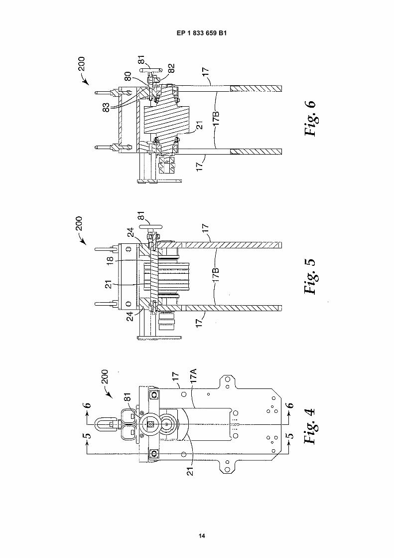
Figure 1 is a front and right side perspective view ofan exemplary rotary welding apparatus according tothe present invention, the apparatus having multiplesub-assemblies;Figure 1A is a front and right side perspective view
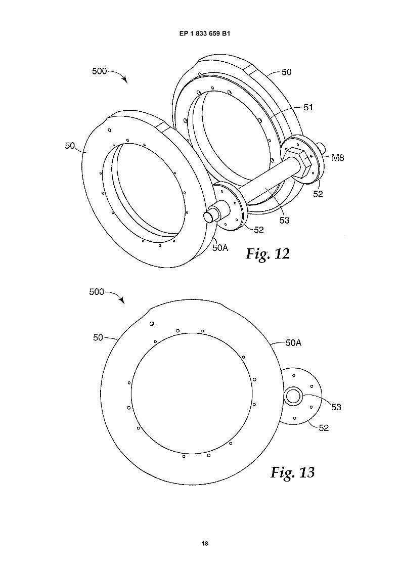
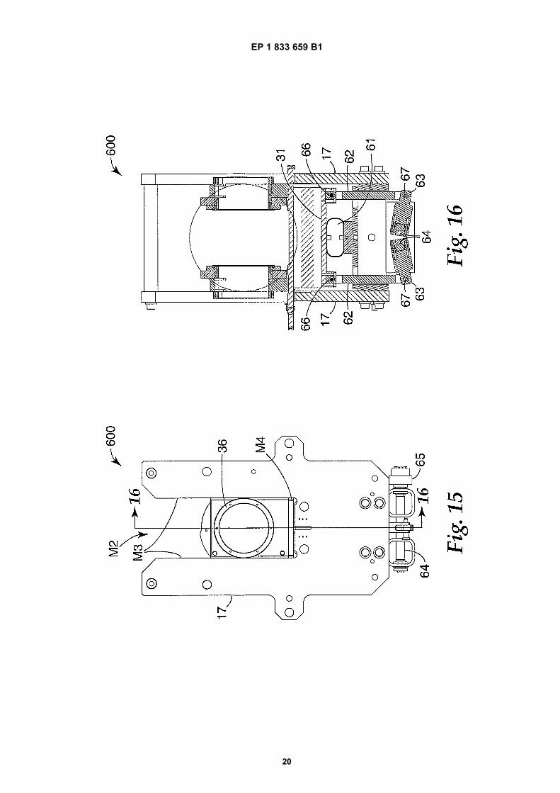
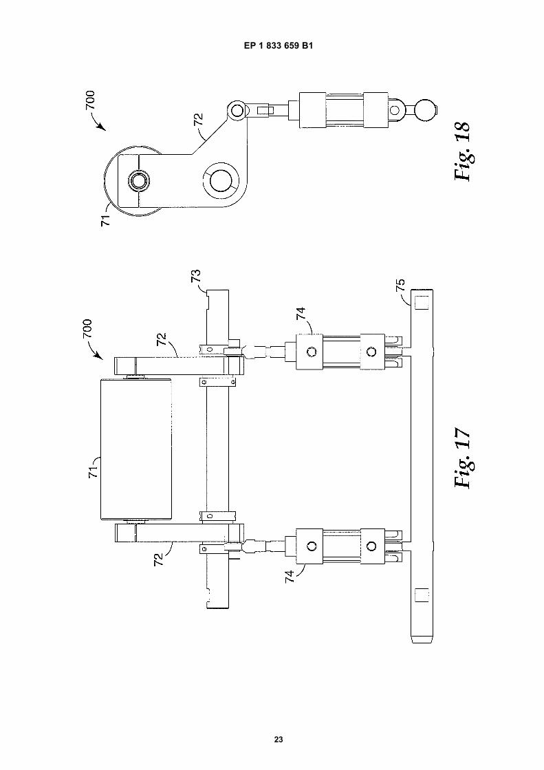
of an alternate exemplary rotary welding apparatusaccording to the present invention, similar to that ofFigure 1;Figure 2 is a front plan view of an anvil roll sub-as-sembly of the apparatus of Figure 1;Figure 3 is a cross-sectional view of the anvil rollsub-assembly taken along line 3-3 of Figure 2;Figure 4 is an enlarged front plan view anvil roll sub-assembly, from the same perspective as Figure 2;Figure 5 is a cross-sectional view of the anvil rollsub-assembly taken along line 5-5 of Figure 4;Figure 6 is a cross-sectional view of the anvil rollsub-assembly taken along line 6-6 of Figure 4;Figure 7 is a perspective view of a horn mount sub-assembly of the apparatus of Figure 1;Figure 8 is a front plan view of the horn mount sub-assembly of Figure 7;Figure 9 is a cross-sectional view of the horn mountsub-assembly taken along line 9-9 of Figure 8;Figure 10 is a front plan view of a horn assembly,which is held by horn mount sub-assembly of Figures7 through 9;Figure 11 is a cross-sectional view of the horn as-sembly taken along line 11-11 of Figure 10;Figure 12 is a perspective view of a horn-anvil gapadjustment sub-assembly of the apparatus of Figure1;Figure 13 is a side plan view of the horn-anvil gapadjustment sub-assembly of Figure 12;Figure 14 is a side plan view of a horn lift sub-as-sembly of the apparatus of Figure 1;Figure 15 is a front plan view of the horn lift sub-assembly of Figure 14;Figure 16 is a cross-sectional view of the horn liftsub-assembly taken along line 16-16 of Figure 15;Figure 16A is an alternate embodiment of a horn liftsub-assembly, similar to the view of Figure 16;Figure 16B is another alternate embodiment of ahorn lift sub-assembly, similar to the view of Figure16;Figure 17 is a front plan view of a nip sub-assemblyof the apparatus of Figure 1;Figure 18 is a side plan view of the nip sub-assemblyof Figure 17;Figure 19 depicts a simplified exemplary embodi-ment of a horn assembly.
Detailed Description
[0014] As provided above, the present invention is di-rected to various improvements in ultrasonic welding andmethods. The improvements can be used in conjunctionwith continuous ultrasonic welding or with rotary type ul-trasonic welding having one or both of the anvil and thehorn rotate. Overall, the improvements are directed tovarious configurations for better measuring, sensing, andcontrolling the gap and the movement between the hornand the anvil.
3 4

EP 1 833 659 B1
4
5
10
15
20
25
30
35
40
45
50
55
[0015] Various alternate embodiments are describedbelow, having features that can be combined with otherembodiments or used alone. For example, an apparatushaving reduced degrees of freedom is described usinga rotary ultrasonic apparatus, where both the anvil andhorn are rotary. The features that provide the reduceddegrees of freedom could likewise be incorporated intoan apparatus where, for example, the horn is rotary andthe anvil is stationary. As another example, a method formonitoring and adjusting the gap between the anvil andhorn, using resonant frequency feedback, is describedusing a stationary apparatus, having both the horn andthe anvil stationary. The features that monitor and adjustthe gap could likewise be incorporated in a rotary appa-ratus. As yet another example, a method for fixing thegap between the anvil and horn is described using a sta-tionary apparatus, having both the horn and the anvilstationary. The features that set the gap could likewisebe incorporated in a rotary apparatus.
Simplified Schematic Diagram
[0016] Figure 19 depicts a simplified embodiment ofthe mounting system depicted in Figures 1-18, below.The system of Figure 19 omits details found in Figures1-18, for the sake of providing a conceptual understand-ing of the system. The purpose of the discussion corre-sponding to Figure 19 is to generally orient the reader tocertain salient features of the mounting system withoutimmersing the reader in the details presented in the dis-cussion relating to Figures 1-18.[0017] As can be seen from Figure 19, the system in-cludes a horn 1900 and an anvil 1902. A gap separatesthe horn 1900 from the anvil 1902. The anvil 1902 ismounted in a housing 1904 that is fastened to ground.The anvil 1902 is free to rotate about its longitudinal axis1906, by virtue of ball bearings 1908 interposed betweenthe anvil 1902 and the housing 1904. Other than theaforementioned rotation about its longitudinal axis 1906,the anvil 1902 exhibits no other degrees of freedom, dueto being mounted within a structure fastened to ground.[0018] The horn 1900 is mounted within a frame 1910.Ball bearings 1912 permit the horn to rotate about itslongitudinal axis 1914. A linking member 1916 joins thetwo halves of the frame 1910. The linking member 1916is attached to a translator 1918 by a pivot 1920. Thus,the frame 1910, linking member 1916, and horn 1900may rotate about an axis defined by the pivot 1920 (theaxis extends in and out of the page).[0019] The translator 1918 is constrained by a struc-ture fastened to earth, so that it exhibits a single degreeof freedom: it may move along a vector perpendicular tothe longitudinal axis 1906 of the anvil 1902. Thus, byvirtue of being fastened to the translator 1918, the frame1910, linking member 1916, and horn 1900 may movealong the aforementioned vector. In other words, the horn1900 (and frame 1910 and linking member 1916) mayadvance toward, or withdraw from, the anvil 1902.
[0020] An actuator 1922 imparts a force upon the trans-lator 1918, so as to urge the horn 1900 toward the anvil1902. The length of the gap between the horn 1900 andthe anvil 1902 is controlled by a pair of threaded fasteners1924, 1926, which extend through the horn’s frame 1910and engage the housing 1904 in which the anvil 1902 ismounted. Thus, by adjusting one threaded fastener 1924or 1926, the frame 1910, linking member 1916, and horn1900 are rotated about the aforementioned axis definedby the pivot 1920. Accordingly, by rotation of the threadedfasteners 1924 and 1926, the longitudinal axis 1914 ofthe horn 1900 may be adjusted, so as to be substantiallyparallel to that of the anvil 1902. Of course, by adjustingboth threaded fasteners 1924 and 1926 in the same fash-ion, the horn 1900 may be advanced toward, or with-drawn from, the anvil 1902 without adjusting the angleof the horn 1900.[0021] Thus, the mounting system of Figure 19 permitsonly two degrees of freedom for positioning of the horn1900. The horn 1900 may be advanced toward, or with-drawn from, the anvil 1902. This degree of freedom ispermitted by virtue of coupling of the housing 1910 to thetranslator 1918, which is confined to motion in one direc-tion. Further, the longitudinal axis 1914 of the horn 1900may be rotated about an axis perpendicular to the longi-tudinal axis 1906 of the anvil 1902. This degree of free-dom is permitted by virtue of the pivot 1920.[0022] The various components of the system depictedin Figure 19 functionally correspond to componentsfound in the system depicted in Figures 1-18. The anvil1902 corresponds to the anvil identified by reference nu-meral 21 in Figure 2 and 3. The housing 1904 in whichthe anvil 1902 is mounted corresponds to the structuresidentified by reference numerals 24 and 25 in Figures 2and 3 (i.e., the anvil 21 is mounted within the structuresidentified by reference numerals 24 and 25, thus makingthem analogous to the housing 1904 in Figure 19).[0023] The horn 1900 corresponds to the horn identi-fied by reference numeral 42 in Figure 11. The frame1910 in which the horn 1900 is mounted corresponds tothe structure identified by reference numeral 32 in Figure7. Further, the linking member 1916 corresponds to thestructure identified by reference numeral 31 in Figure 7(i.e., the structure identified by reference numeral 31 joinsboth halves of the frame 32, thus making it analogous tothe linking member 1916). The ball bearings 1912 uponwhich the horn 1900 rides correspond to the nodal mountidentified by reference numerals 43, 44, and 45 in Figure11 (i.e., the nodal mounts 43, 44, and 45 permit rotationof the horn 42, in a manner appropriate for a vibratingbody. Despite the simplified depiction in Figure 19, a vi-brating body, such as a horn, would damage the ball bear-ings if riding thereupon. Hence, the need for nodal mount43, 44, and 45.).[0024] The pivot 1920 corresponds to the pivot identi-fied by reference numeral M12 in Figure 16A. In otherwords, the pivot M12 permits rotation of the frame 32,and therefore rotation of the horn 42. Translator 1918
5 6

EP 1 833 659 B1
5
5
10
15
20
25
30
35
40
45
50
55
corresponds to translation member M11, also depictedin Figure 16A. In other words, the frame 32 is joined totranslation member M11, which is permitted one degreeof freedom-it may advance toward or withdraw from theanvil 21. The actuator 1922 corresponds to the air bladderidentified by reference numeral 61 in Figure 14. In otherwords, the air bladder 61 generates a force to urge thetranslator M11 toward the anvil 21.[0025] The threaded fasteners 1924 and 1926 corre-spond to the cams identified by reference numeral 50 inFigures 12 and 13. In other words, the cams 50 ride uponthe cam followers 27 (shown in Figure 3) attached to theframe 24, 25 in which the anvil 21 is mounted, and therebyalter the distance between the horn 42 and the anvil 21and/or the orientation of the longitudinal axis of the horn42 when rotated.[0026] The remaining discussion with respect to Fig-ures 1-18 pertains to disclosure of an exemplary embod-iment of a system for mounting an ultrasonic welding de-vice, as that system appears in view of all of its detailsand features.
Controlling Gap by Reduced Degrees of Freedom
[0027] Referring to Figure 1, a rotary welding module100 is illustrated. Rotary welding module 100 includesfeatures that limit the degrees-of-freedom of the horn inrelation to the anvil, thus better controlling the gap andthe movement between the horn and the anvil during thewelding process.[0028] Module 100 includes a first sub-assembly, par-ticularly an anvil assembly 200, a second sub-assembly,particularly a horn mount assembly 300, a third sub-as-sembly, particularly a horn assembly 400, a fourth sub-assembly, particularly a horn-anvil gap adjustment as-sembly 500, a fifth sub-assembly, particularly a horn lift-ing assembly 600, and a sixth sub-assembly, particularlya nip assembly 700. Additional details regarding each ofthese sub-assemblies are provided below. Also illustrat-ed in Figure 1 as a part of rotary welding module 100 areside plates 17, tie rods 18, a horn servomotor 19, and ananvil servomotor and gearbox 11.[0029] Figures 2 and 3 provide a detailed view of anvilassembly 200. Anvil assembly 200 includes an anvil roll21 having a roll face 22 and journals 23. Anvil roll 21 canbe any suitable roll, such as a die roll, embossing roll,printing roll, or welding rolls. Anvil bearing blocks 24 aremounted to anvil frame 25. Anvil roll 21 is mounted tobearing blocks 24 using by means of precision duplexball bearings 26. Anvil roll 21 is configured to rotatearound an axis, preferably an axis extending longitudi-nally through the center of roll 21. Bearing locknuts 28hold the duplex pairs 26 together and on journals 23.Anvil assembly 200 also includes two cam-follower bear-ing assemblies 27 mounted on anvil-roll journals 23.These cam follower assemblies 27 are held onto journals23 using bearing locknuts 29.[0030] One of the features of this invention is the ability
to move the anvil assembly 200 slightly cross-web; thiscross-web motion is called "side-lay". Referring to Fig-ures 4 through 6, additional views of anvil roll assembly200, supported by side plates 17, are illustrated. Anvilroll 21 is mounted on tie rods 18 and to side plates 17,in a manner so that roll 21 can rotate around its longitu-dinal axis. In this embodiment, bearing blocks 24 are sup-ported by tie rods 18. Anvil roll 21 is fixed to tie rods 18by way of shaft clamps M1. When clamps M1 are in aloosened condition, anvil roll assembly 200 can bemoved in relation to side plates 17, for example by usinga threaded rod 80 attached to a handle 81. A threadedbar 82 is fixed to the side plates 17 and bearings 83 areattached to one of bearing blocks 24.[0031] Figure 7 shows horn mount assembly 300,which includes a mount frame 31, horn-bearing blocks32, a horn drive motor 19, a horn drive means, such asbelt 34, and horn-anvil gap adjustment assembly 500.Figures 8 and 9 show additional views and features ofhorn mount assembly 300.[0032] When horn mount assembly 300 is installed inwelding module 100, slots M2 (as shown in Figure 15) inside plates 17 as shown in Fig. 1 guide and allow hornmount assembly 300 to move. In particular, surfaces 36on bearing blocks 32 contact surfaces M3 of side plates17; preferably, at least a portion of bearing block 32 fitswithin slot M2. In some embodiments, surfaces 36 arecylindrical surfaces, though this is not essential.[0033] Surfaces 36 inhibit movement of assembly 300in two directions, thus removing two degrees of freedom,one linear along the X-axis and one rotational around theY-axis (see Figure 7). Another rotational degree-of-free-dom around the Z-axis is removed by rest buttons M4 onmount frame 17.[0034] Bearing blocks 32 also have a second set ofsurfaces 38, which also in an exemplary embodiment arecylindrical surfaces. The radius of these surfaces 38 ishalf the distance between the inside or bearing surfaces17b of side plates 17 (Figure 1A). Surfaces 38 remove atranslational degree of freedom along the Z-axis.[0035] It is well recognized that all rigid bodies havesix degrees-of-freedom. The features described aboveremove four degrees-of-freedom.[0036] The two remaining available degrees of free-dom are translational movement along the Y-axis (to-wards and away from the anvil) and rotational movementalong the X-axis. The combination of these two degrees-of-freedom allow the gap between horn 30 and the anvilto be adjusted independently on both sides of horn 30.[0037] Figures 10 and 11 shows horn assembly 400,which includes horn 42, nodal mounts 43, horn bearingrings 44, horn bearings 45, and horn drive sprocket 46.Horn 42 and nodal mounts 43 (which are described inU.S. Pat. No. 6,786,384, to Gopal Haregoppa, which isherein incorporated by reference in its entirety) illustratedare one of several possible designs, but are preferred forthis embodiment.[0038] Figures 12 and 13 show horn gap or horn-anvil
7 8

EP 1 833 659 B1
6
5
10
15
20
25
30
35
40
45
50
55
gap adjustment assembly 500. Assembly 500 includesfirst and second cams 50 and a drive gear 51 attachedto the cams. The inner cylindrical surface of the cams,M6, rests on the cylindrical surfaces M5 of assembly 300(Fig. 7). Clearance between surfaces M5 and M6 allowsthe cams 50 to rotate about the z-axis.[0039] Gear shaft 53 is a non-rotating shaft that ismounted between bearing blocks 32 using holes M7 (Fig.7). Driving gears 52 are rotatably mounted to gear shaft53. the driving gears 52 are rotated independently usinga wrench the hex feature M8 to substantially parallel thez-axis of the anvil. Rotation of the driving gears 52 causesthe cams 50 to rotate.[0040] In use, the outer cam surface 50a is machinedto generate a linear function, h = Aθ, where h is the totalrise of the cam, θ is the angle of rotation of the cam, andA is a constant. In a preferred embodiment, cams 50generate a rise of 0.100 inch (about 2.5 mm) over 300degrees of cam rotation. This provides an adjustmentresolution of 3/10000 inch per degree (about 0.0076 mmper degree).[0041] Figure 14 shows horn lift assembly 600, whichis used to move, generally raise and lower, horn mountassembly 300 in relation to side plates 17. The motionof horn mounting assembly 300 is stopped when camsurface 50a contact cam followers 27 of anvil assembly200.[0042] Referring to Figure 14, horn lift assembly 600includes lift frame 60 fixedly attached to side plates 17.Attached to lift frame 60 is pneumatic bellows 61, whichis configured to expand and decrease, as desired. In use,pressurizing bellows 61 applies force to horn mount as-sembly 300 to push assembly 300 towards anvil roll 21;other force generators, such as linear actuators, pneu-matic cylinders and hydraulic cylinders could alternatelybe used. As discussed previously, horn mount assembly300 has two remaining degrees-of-freedom. One is trans-lational along the Y axis and one rotational along theX(θx)-axis (Figure 14).[0043] Figures 15 and 16 show additional views of hornlift assembly 600. In this embodiment, a geared 7-barlinkage, with pivot clearance, is used to control the rota-tion of horn mount assembly 300 in relation to side plates17 and mount frame 31. This linkage includes connectinglink arms 62, pivot arms 63, pivot shafts 64, gears 65,and pivot connections 66, 67. As bellows 61 lifts hornmount assembly300, connecting link arms 62 raise theends of pivot arms 63, which rotate an equal amount,due to arms 63 being geared together. If there were noclearance or slop in the pivot joints 66, 67, horn mountassembly 300 would only move vertically and the rota-tional degree-of-freedom (θx) would be removed. How-ever, by the inclusion of clearance to joints 66, 67, anamount of rotation is allowed.[0044] Figure 16A and B shows the geared 7-bar link-age 600A,along with the horn mount assembly 300 inmore basic kinematic form. Referring to Figure 16A, inthis embodiment, link 1 is ground. Linkage 600A includes
connecting link arms 62A, pivot arms 63A, pivot shafts64A, and pivot connects 66A, 67A. Connecting link arms62A raise the ends of pivot arms 63A at joint 67A, arms63A which rotate an equal amount, due to arms 63A beinggeared together.[0045] Pivot arms 63A are two binary links that are con-nected to ground and to link arms 62A via joints 64A and67A, respectively. Pivot arms 63A are also connected toeach other using a gear joint. The ratio of the gear jointis 1:1. Link arms 62A are also binary links that are con-nected to pivot arms 63A and to mount frame 31A viarevolute joints 67A, 66A respectively. Mount frame 31Ais a ternary link that is connected to arms 62A and slideblock M11 with pivot joints 67A and M12. Slider blockM11 is connected to ground and mount frame 31A usingjoints M10 and M12. Slider block M11 controls the motionof mount frame 31A so that mount frame 31A has only atranslational and rotational degree-of-freedom.[0046] Linkage 600A includes joint clearance at joints66A by including an oversized hole. Additionally or alter-natively, joint clearance could be present at pivot joints67A. In a conventional geared-7-bar linkage mechanismwithout joint clearances, the motion of mount frame 31Awould only be translational as pivot arms 63 A are rotated.By having the joint clearance, the horn 42 of the hornmount assembly300, which is connected to mount frame31A, can be adjusted with limited angular motion.[0047] The clearance in the joint may also be accom-plished using clearance controls/limits angular motion θx,with the use of a slot, as is illustrated in Figure 16B. InFigures 16B, linkage 600B includes connecting link arms62B, pivot arms 63B, pivot shafts 64B, and pivot connec-tions 66B, 67B. Pivot connections 66B include a slot thatprovides joint clearance. If L is the distance betweenjoints 66B, and C is the joint clearance, then the allowedangle of rotation, α, is given by,
[0048] In a preferred embodiment, C is equal to 0.762mm (0.03 inch) and L is301.8 mm (11.88 inch), thus providing α as 0.3 degrees.[0049] The clearance, either an oversized hole, a slot,or other, is selected so that the rotation allows variationsin the gap between horn 42 and the anvil to adjust formanufacturing tolerances and process variations. Theclearance is not, however, so great as to prevent or inhibitmounting of horn 42 and stopping correctly on cams 50.[0050] Figures 17 and 18 shows nip assembly 700. Nipassembly includes nip roller 71, nip arms 72, pivot shaft73, nip cylinders 74, and cylinder support shaft 75.[0051] An alternate exemplary rotary welding moduleis illustrated in Figure 1A as apparatus 100A. Similar toapparatus 100 of Figure 1, apparatus 100A has multiplesub-assemblies. Shown in Figure 1A are anvil assembly
9 10

EP 1 833 659 B1
7
5
10
15
20
25
30
35
40
45
50
55
200A which includes anvil roll 21A, horn assembly 400A,and horn lifting assembly 600A. Also shown in Figure 1Aare side plates 17A. An alternate method of limiting thehorn assembly to two degrees of freedom uses leafsprings M13 and M14. Apparatus 100A includes leafsprings M13, typically at least two pairs of leaf springsM14. Each pair of leaf springs M14 is attached to differentbearing blocks 32 and different side plates 17A.[0052] A welding apparatus, based on reducing the de-grees-of-freedom available to better control the gap be-tween the anvil and the horn, generally includes anvil roll21 or other rotatable tool roll having an first axis, and amounting system for supporting anvil roll 21 so that it canrotate about its first axis. The mounting system is config-ured such that anvil roll 21 has only two additional de-grees of freedom, the first additional degree of freedombeing translational motion in a direction perpendicular tothe first axis, and the second additional degree of free-dom being rotational motion about a second axis that isboth perpendicular to the first axis and the direction ofthe first additional degree of freedom. This limited rangeof movement stabilizes the distance between the anviland the horn.[0053] Upon reading and understanding the foregoingprocess for controlling an ultrasonic welding system, oneof ordinary skill in the art will appreciate that gap controlfor a system can be achieved by measuring the operatingfrequency of the horn, and then adjusting the force, forexample, pressure, that controls the gap. The specificequations can be derived or determined empirically forany horn geometry, including linear and rotary horns.[0054] The various embodiments described above areprovided by way of illustration only and should not beconstrued to limit the invention. Those skilled in the artwill readily recognize various modifications and changesthat may be made to the present invention without fol-lowing the example embodiments and applications illus-trated and described herein, and without departing fromthe scope of the present invention, which is set forth inthe following claims.
Claims
1. An apparatus for ultrasonic welding a web of indef-inite length, comprising:
a rotatable tool roll (42) having a first longitudinalaxis of rotation (1906), wherein the rotatable toolroll is rotatable ultrasonic welding horn (1900);a source of ultrasonic energy coupled to the ro-tatable ultrasonic welding horn (1900);a mounting system (100, 300, 1910) for support-ing the rotatable tool roll so that the rotatabletool roll can rotate about the first longitudinal axis(1914) and such that the rotatable tool roll hasonly two additional degrees of freedom, the firstadditional degree of freedom being translational
motion in a direction perpendicular to the firstlongitudinal axis (1914), and the second addi-tional degree of freedom being rotational motionabout a pivot (1920) through a second longitu-dinal axis that is both perpendicular to the firstlongitudinal axis and the direction of the first ad-ditional degree of freedom;an anvil roll (21, 1902) mounted adjacent to themounting system (100, 300, 1910); anda force generator (61, 1918) positioned so as toapply force to the mounting system (100, 300,1910) so as to urge the rotatable ultrasonic weld-ing horn (1900) towards the anvil roll (21, 1902).
2. The apparatus according to claim 1 wherein themounting system (100/300) comprisesa frame having two side plates(17), each side platehaving a bearing surface and having a slot therein,a pair of support elements (32) each adapted to en-gage the tool roll in such a fashion that the tool roll(42) is free to rotate, wherein each support elementcomprisesa slide portion slidably engaging one of the slots(17A), anda bearing portion (38) having a curved surface en-gaging the bearing surface.
3. The apparatus according to claim 1 wherein themounting system comprisesa frame having two side plates,a pair of support elements each adapted to engagethe tool roll in such a fashion that the tool roll is freeto rotate, andat least two pairs of leaf springs (M13), each pair ofleaf springs attached to a different one of the supportelements and a different one of the side plates.
4. The apparatus according to claim 1 wherein the forcegenerator is selected from the group consisting ofair bellows (61), linear actuators, pneumatic and hy-draulic cylinders.
5. The apparatus according to claim 1 further compris-ing means for limiting the maximum amount of mo-tion within the second additional degree of freedom.
6. The apparatus according to claim 5 wherein the lim-iting means is a geared 7-bar linkage (62-67).
7. A method of ultrasonic welding a web of indefinitelength, comprising:
providing a mounting system (100, 300, 1910)for supporting a rotatable tool roll (42), whereinthe rotatable tool roll is an ultrasonic weldinghorn (1900) having a first longitudinal axis(1906) within the mounting system so that thetool roll (42) can rotate about the first longitudinal
11 12

EP 1 833 659 B1
8
5
10
15
20
25
30
35
40
45
50
55
axis and such that the rotatable tool roll has onlytwo additional degrees of freedom, the first ad-ditional degree of freedom being translationalmotion in a direction perpendicular to the firstlongitudinal axis, and the second additional de-gree of freedom being rotational motion about apivot (1920) through a second longitudinal axisthat is both perpendicular to the first longitudinalaxis and the direction of the first additional de-gree of freedom;providing an anvil roll (21, 1902) mounted adja-cent to the mounting system (100, 300, 1910);providing a force generator (61, 1918) posi-tioned so as to apply force to the mounting sys-tem (100, 300, 1910) so as to urge the rotatableultrasonic welding horn (1900) towards the anvilroll (21, 1902);providing a source of ultrasonic energy coupledto the rotatable ultrasonic welding horn (1900);andcontacting the web with the rotatable ultrasonicwelding horn (1900) so as to ultrasonically weldthe web.
Patentansprüche
1. Vorrichtung zum Ultraschallschweißen einer Bahnvon unbegrenzter Länge, umfassend:
eine drehbare Werkzeugrolle (42) mit einer ers-ten längsverlaufenden Rotationsachse (1906),wobei die drehbare Werkzeugrolle eine drehba-re Ultraschallschweiß-Sonotrode (1900) ist;eine Quelle von Ultraschall-Energie, die an diedrehbare Ultraschallschweiß-Sonotrode (1900)gekoppelt ist;ein Montagesystem (100, 300, 1910), das diedrehbare Werkzeugrolle trägt, so dass sich diedrehbare Werkzeugrolle um die erste Längs-achse (1914) drehen kann und so dass die dreh-bare Werkzeugrolle nur zwei zusätzliche Frei-heitsgrade aufweist, wobei der erste zusätzlicheFreiheitsgrad eine translatorische Bewegung ineine Richtung ist, die senkrecht zur erstenLängsachse (1914) ist; und wobei der zweite zu-sätzliche Freiheitsgrad eine Drehbewegungüber einen Drehpunkt (1920) um eine zweiteLängsachse ist, die sowohl senkrecht zur erstenLängsachse als auch zur Richtung des erstenzusätzlichen Freiheitsgrades ist;eine Ambossrolle (21, 1902), die am Montage-system (100, 300, 1910) angrenzend befestigtist; undeinen Krafterzeuger (61, 1918), der so positio-niert ist, dass Kraft auf das Montagesystem(100, 300, 1910) ausgeübt wird, sodass diedrehbare Ultraschallschweiß-Sonotrode (1900)
in Richtung der Ambossrolle (21, 1902) gedrücktwird.
2. Vorrichtung nach Anspruch 1, wobei das Montage-system (100/300) umfasst:
einen Rahmen mit zwei Seitenplatten (17), wo-bei jede Seitenplatte über eine Auflagefläche miteiner Aussparung darin verfügt,ein Paar Stützelemente (32), die so eingestelltsind, dass sie mit der Werkzeugrolle (42) so inEingriff treten, dass sie sich frei drehen kann,wobei jedes Stützelementeinen Schiebeabschnitt umfasst, der durchSchieben mit einer der Aussparungen (17A) inEingriff tritt, undeinen Auflageabschnitt (38) mit einer abgerun-deten Oberfläche, der mit der Auflagefläche inEingriff tritt.
3. Vorrichtung nach Anspruch 1, wobei das Montage-system umfasst:
einen Rahmen mit zwei Seitenplatten,ein Paar Stützelemente, die so eingestellt sind,dass sie mit der Werkzeugrolle so in Eingriff tre-ten, dass sie sich frei drehen kann, undmindestens zwei Paar Blattfedern (M13), wobeijedes Paar jeweils an einem anderen Stützele-ment und einer anderen Seitenplatte befestigtist.
4. Vorrichtung nach Anspruch 1, wobei der Krafterzeu-ger aus der Gruppe bestehend aus Luftbälgen (61),Hubantrieben und Pneumatik- und Hydraulikzylin-dern ausgewählt wird.
5. Vorrichtung nach Anspruch 1, ferner Mittel zur Be-grenzung des maximalen Bewegungsausmaßes in-nerhalb des zweiten zusätzlichen Freiheitsgradesumfassend.
6. Vorrichtung nach Anspruch 5, wobei das Begren-zungsmittel ein 7-armiges Zahnradverbindungsmit-tel (62-67) ist.
7. Verfahren zum Ultraschallschweißen einer Bahnvon unbegrenzter Länge, umfassend:
Bereitstellen eines Montagesystems (100, 300,1910), das eine drehbare Werkzeugrolle (42)trägt, wobei die drehbare Werkzeugrolle eine Ul-traschallschweiß-Sonotrode (1900) mit einerersten Längsachse (1906) im Montagesystemist, so dass die Werkzeugrolle (42) um die ersteLängsachse gedreht werden kann und so dassdie drehbare Werkzeugrolle nur zwei zusätzli-che Freiheitsgrade aufweist, wobei der erste zu-
13 14

EP 1 833 659 B1
9
5
10
15
20
25
30
35
40
45
50
55
sätzliche Freiheitsgrad eine translatorische Be-wegung in eine Richtung ist, die senkrecht zurersten Längsachse ist; und wobei der zweite zu-sätzliche Freiheitsgrad eine Drehbewegungüber einen Drehpunkt (1920) um eine zweiteLängsachse ist, die sowohl senkrecht zur erstenLängsachse als auch zur Richtung des erstenzusätzlichen Freiheitsgrades ist;Bereitstellen einer Ambossrolle (21, 1902), diean das Montagesystem (100, 300, 1910) an-grenzend befestigt ist;Bereitstellen eines Krafterzeugers (61, 1918),der so positioniert ist, dass Kraft auf das Mon-tagesystem (100, 300, 1910) ausgeübt wird, so-dass die drehbare Ultraschallschweiß-Sonotro-de (1900) in Richtung der Ambossrolle (21,1902) gedrückt wird;Bereitstellen einer Quelle von Ultraschall-Ener-gie, die an die drehbare Ultraschallschweiß-So-notrode (1900) gekoppelt ist; undBerühren der Bahn mit der drehbaren Ultra-schallschweiß-Sonotrode (1900) zum Ultra-schallschweißen der Bahn.
Revendications
1. Appareil de soudage par ultrasons d’une bande delongueur indéfinie, comprenant :
un rouleau d’outillage rotatif (42) comportant unpremier axe de rotation longitudinal (1906),dans lequel le rouleau d’outillage rotatif est uncornet de soudage par ultrasons rotatif (1900) ;une source d’énergie ultrasonore couplée aucornet de soudage par ultrasons rotatif (1900) ;un système de montage (100, 300, 1910) des-tiné à soutenir le rouleau d’outillage rotatif desorte que le rouleau d’outillage rotatif peut tour-ner autour du premier axe longitudinal (1914) etde sorte que le rouleau d’outillage rotatif n’a quedeux degrés de liberté supplémentaires, le pre-mier degré de liberté supplémentaire étant lemouvement de translation dans une directionperpendiculaire au premier axe longitudinal(1914) et le deuxième degré de liberté supplé-mentaire étant un mouvement de rotation autourd’un pivot (1920) par l’intermédiaire d’un deuxiè-me axe longitudinal qui est à la fois perpendicu-laire au premier axe longitudinal et à la directiondu premier degré de liberté supplémentaire ;un rouleau formant enclume (21, 1902) montéadjacent au système de montage (100, 300,1910) ; etun générateur de force (61, 1918) positionné demanière à appliquer une force au système demontage (100, 300, 1910) de façon à pousserle cornet de soudage par ultrasons rotatif (1900)
vers le rouleau formant enclume (21, 1902).
2. Appareil selon la revendication 1, dans lequel le sys-tème de montage (100/300) comprendun bâti comportant deux plaques latérales (17), cha-que plaque latérale comportant une surface d’appuipourvue d’une fente,une paire d’éléments support (32) conçus pour veniren prise avec le rouleau d’outillage de sorte que lerouleau d’outillage (42) est libre de tourner, dans le-quel chaque élément support comprendune partie coulissante venant en prise de manièrecoulissante avec l’une des fentes (17A), etune partie palier (38) comportant une surface incur-vée venant en prise avec la surface d’appui.
3. Appareil selon la revendication 1, dans lequel le sys-tème de montage comprendun bâti comportant deux plaques latérales,une paire d’éléments support conçus pour venir enprise avec le rouleau d’outillage de sorte que le rou-leau d’outillage est libre de tourner, etau moins deux paires de ressorts à lames (M13),chaque paire de ressorts à lames étant fixée à unélément support distinct et à une plaque latérale dis-tincte.
4. Appareil selon la revendication 1, dans lequel le gé-nérateur de force est choisi dans le groupe constituéde soufflets à air comprimé (61), d’actionneurs li-néaires, de vérins pneumatiques et hydrauliques.
5. Appareil selon la revendication 1, comprenant enoutre un moyen pour limiter la quantité maximale demouvement au sein du deuxième degré de libertésupplémentaire.
6. Appareil selon la revendication 5, dans lequel lemoyen de limitation est une tringlerie à 7 barres àengrenages (62-67).
7. Procédé de soudage par ultrasons d’une bande delongueur indéfinie, comprenant les étapes consis-tant à :
fournir un système de montage (100, 300,1910)destiné à soutenir un rouleau d’outillage rotatif(42), dans lequel le rouleau d’outillage rotatif estun cornet de soudage par ultrasons (1900) com-portant un premier axe longitudinal (1906) dansle système de montage de telle sorte que le rou-leau d’outillage (42) peut tourner autour du pre-mier axe longitudinal et de telle sorte que le rou-leau d’outillage rotatif n’a que deux degrés deliberté supplémentaires, le premier degré de li-berté supplémentaire étant le mouvement detranslation dans une direction perpendiculaireau premier axe longitudinal, et le deuxième de-
15 16

EP 1 833 659 B1
10
5
10
15
20
25
30
35
40
45
50
55
gré de liberté supplémentaire étant un mouve-ment de rotation autour d’un pivot (1920) parl’intermédiaire d’un deuxième axe longitudinalqui est à la fois perpendiculaire au premier axelongitudinal et à la direction du premier degréde liberté supplémentaire ;fournir un rouleau formant enclume (21, 1902)monté adjacent au système de montage (100,300, 1910) ;fournir un générateur de force (61, 1918) posi-tionné de manière à appliquer une force au sys-tème de montage (100, 300, 1910) de façon àpousser le cornet de soudage par ultrasons ro-tatif (1900) vers le rouleau formant enclume (21,1902) ;fournir une source d’énergie ultrasonore cou-plée au cornet de soudage par ultrasons rotatif(1900) ; etamener la bande en contact avec le cornet desoudage par ultrasons rotatif (1900) afin de sou-der la bande par ultrasons.
17 18

EP 1 833 659 B1
11

EP 1 833 659 B1
12

EP 1 833 659 B1
13
EP 1 833 659 B1
14

EP 1 833 659 B1
15

EP 1 833 659 B1
16

EP 1 833 659 B1
17
EP 1 833 659 B1
18

EP 1 833 659 B1
19
EP 1 833 659 B1
20

EP 1 833 659 B1
21

EP 1 833 659 B1
22
EP 1 833 659 B1
23

EP 1 833 659 B1
24

EP 1 833 659 B1
25
REFERENCES CITED IN THE DESCRIPTION
This list of references cited by the applicant is for the reader’s convenience only. It does not form part of the Europeanpatent document. Even though great care has been taken in compiling the references, errors or omissions cannot beexcluded and the EPO disclaims all liability in this regard.
Patent documents cited in the description
• US 5976316 A [0004]• EP 0689930 A [0005]• US 2003057259 A1 [0006]
• US 2002062903 A1 [0007]• US 6786384 B, Gopal [0037]