Aim: Apparatus: Theory: Procedure:
16
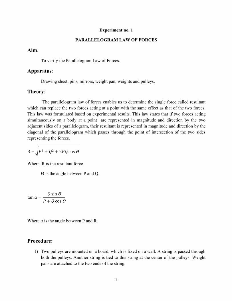
1 Experiment no. 1 PARALLELOGRAM LAW OF FORCES Aim: To verify the Parallelogram Law of Forces. Apparatus: Drawing sheet, pins, mirrors, weight pan, weights and pulleys. Theory: The parallelogram law of forces enables us to determine the single force called resultant which can replace the two forces acting at a point with the same effect as that of the two forces. This law was formulated based on experimental results. This law states that if two forces acting simultaneously on a body at a point are represented in magnitude and direction by the two adjacent sides of a parallelogram, their resultant is represented in magnitude and direction by the diagonal of the parallelogram which passes through the point of intersection of the two sides representing the forces. R= cos Ɵ Where R is the resultant force Ɵ is the angle between P and Q. tan sin Ɵ cos Ɵ Where α is the angle between P and R. Procedure: 1) Two pulleys are mounted on a board, which is fixed on a wall. A string is passed through both the pulleys. Another string is tied to this string at the center of the pulleys. Weight pans are attached to the two ends of the string.
-
Upload
khangminh22 -
Category
Documents
-
view
4 -
download
0
Transcript of Aim: Apparatus: Theory: Procedure:
1
Experiment no. 1
PARALLELOGRAM LAWOF FORCES
Aim:
To verify the Parallelogram Law of Forces.
Apparatus:
Drawing sheet, pins, mirrors, weight pan, weights and pulleys.
Theory:
The parallelogram law of forces enables us to determine the single force called resultantwhich can replace the two forces acting at a point with the same effect as that of the two forces.This law was formulated based on experimental results. This law states that if two forces actingsimultaneously on a body at a point are represented in magnitude and direction by the twoadjacent sides of a parallelogram, their resultant is represented in magnitude and direction by thediagonal of the parallelogram which passes through the point of intersection of the two sidesrepresenting the forces.
R = �� � �� � ���cos Ɵ
Where R is the resultant force
Ɵ is the angle between P and Q.
tan� �� sinƟ
� � � cos Ɵ
Where α is the angle between P and R.
Procedure:
1) Two pulleys are mounted on a board, which is fixed on a wall. A string is passed throughboth the pulleys. Another string is tied to this string at the center of the pulleys. Weightpans are attached to the two ends of the string.
2
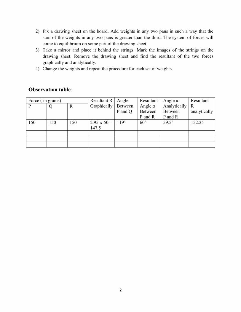
2) Fix a drawing sheet on the board. Add weights in any two pans in such a way that thesum of the weights in any two pans is greater than the third. The system of forces willcome to equilibrium on some part of the drawing sheet.
3) Take a mirror and place it behind the strings. Mark the images of the strings on thedrawing sheet. Remove the drawing sheet and find the resultant of the two forcesgraphically and analytically.
4) Change the weights and repeat the procedure for each set of weights.
Observation table:
Force ( in grams) Resultant RGraphically
AngleBetweenP and Q
ResultantAngle αBetweenP and R
Angle αAnalyticallyBetweenP and R
ResultantRanalytically
P Q R
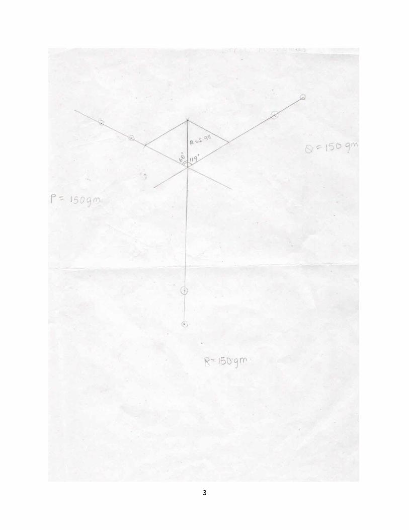
150 150 150 2.95 x 50 =147.5
119˚ 60˚ 59.5˚ 152.25
3
4
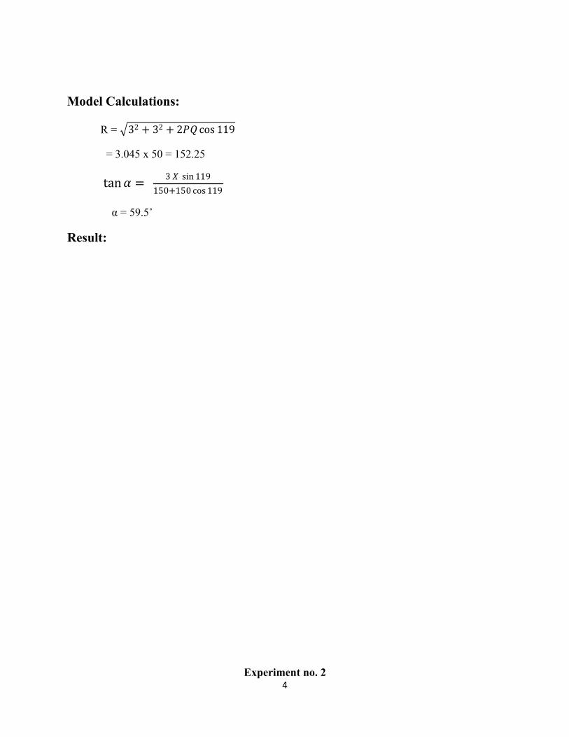
Model Calculations:
R = �� � �� � ���cos ��h
= 3.045 x 50 = 152.25
tan� � � � sin ��h�Mi��Mi cos ��h
α = 59.5˚
Result:
Experiment no. 2
5
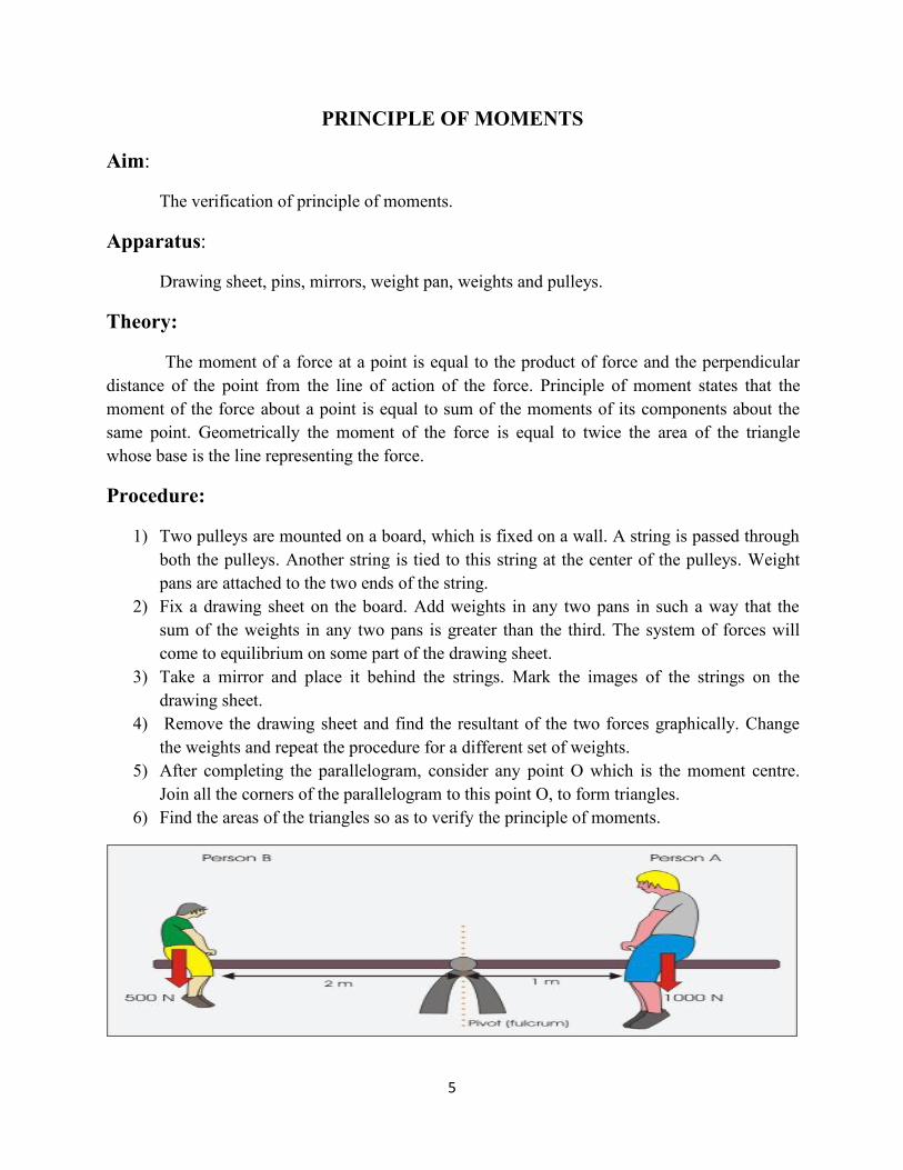
PRINCIPLE OF MOMENTS
Aim:
The verification of principle of moments.
Apparatus:
Drawing sheet, pins, mirrors, weight pan, weights and pulleys.
Theory:
The moment of a force at a point is equal to the product of force and the perpendiculardistance of the point from the line of action of the force. Principle of moment states that themoment of the force about a point is equal to sum of the moments of its components about thesame point. Geometrically the moment of the force is equal to twice the area of the trianglewhose base is the line representing the force.
Procedure:
1) Two pulleys are mounted on a board, which is fixed on a wall. A string is passed throughboth the pulleys. Another string is tied to this string at the center of the pulleys. Weightpans are attached to the two ends of the string.
2) Fix a drawing sheet on the board. Add weights in any two pans in such a way that thesum of the weights in any two pans is greater than the third. The system of forces willcome to equilibrium on some part of the drawing sheet.
3) Take a mirror and place it behind the strings. Mark the images of the strings on thedrawing sheet.
4) Remove the drawing sheet and find the resultant of the two forces graphically. Changethe weights and repeat the procedure for a different set of weights.
5) After completing the parallelogram, consider any point O which is the moment centre.Join all the corners of the parallelogram to this point O, to form triangles.
6) Find the areas of the triangles so as to verify the principle of moments.
6
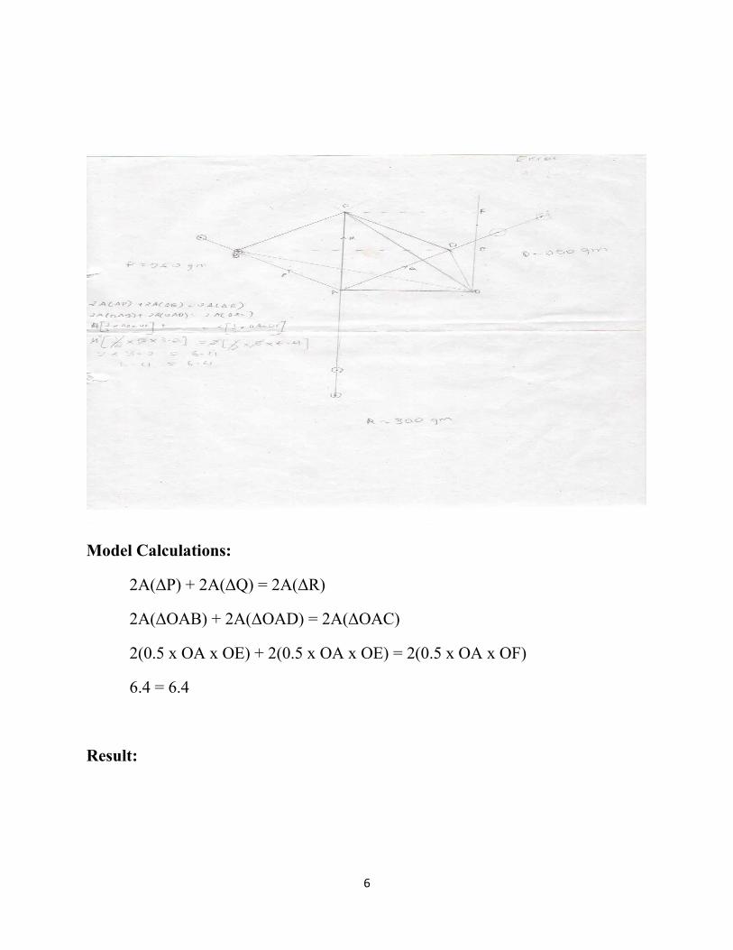
Model Calculations:
2A(ΔP) + 2A(ΔQ) = 2A(ΔR)
2A(ΔOAB) + 2A(ΔOAD) = 2A(ΔOAC)
2(0.5 x OA x OE) + 2(0.5 x OA x OE) = 2(0.5 x OA x OF)
6.4 = 6.4
Result:
7
Experiment no. 3
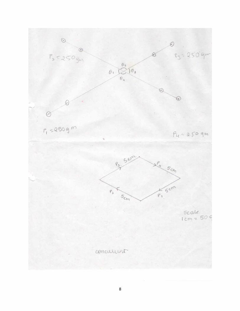
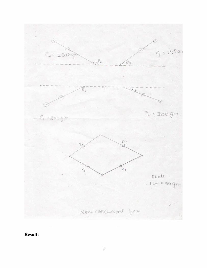
CONCURRENT AND NON-CONCURRENT FORCES
Aim:
To verify the system of given concurrent and non-concurrent forces are in equilibriumusing converse of the law of polygon of forces.
Apparatus:
Drawing sheet, pins, mirrors, weight pan, weights and pulleys.
Theory:
According to the converse of the law of polygon of forces, if the number of forces actingat a point is represented in magnitude and direction, by the sides of a closed polygon taken inorder, the forces shall be in equilibrium.
Procedure:
1) Two pulleys are mounted on a board, which is fixed on a wall. A string is passed throughboth the pulleys. Another string is tied to this string at the center of the pulleys. Weightpans are attached to the two ends of the string.
2) Fix a drawing sheet on the board. Add weights in any two pans in such a way that thesum of the weights in any two pans is greater than the third. The system of forces willcome to equilibrium on some part of the drawing sheet.
3) Take a mirror and place it behind the strings. Mark the images of the strings on thedrawing sheet.
4) Change the weights and repeat the procedure for a different set of weights.5) Remove the drawing sheets and draw the closed polygon.
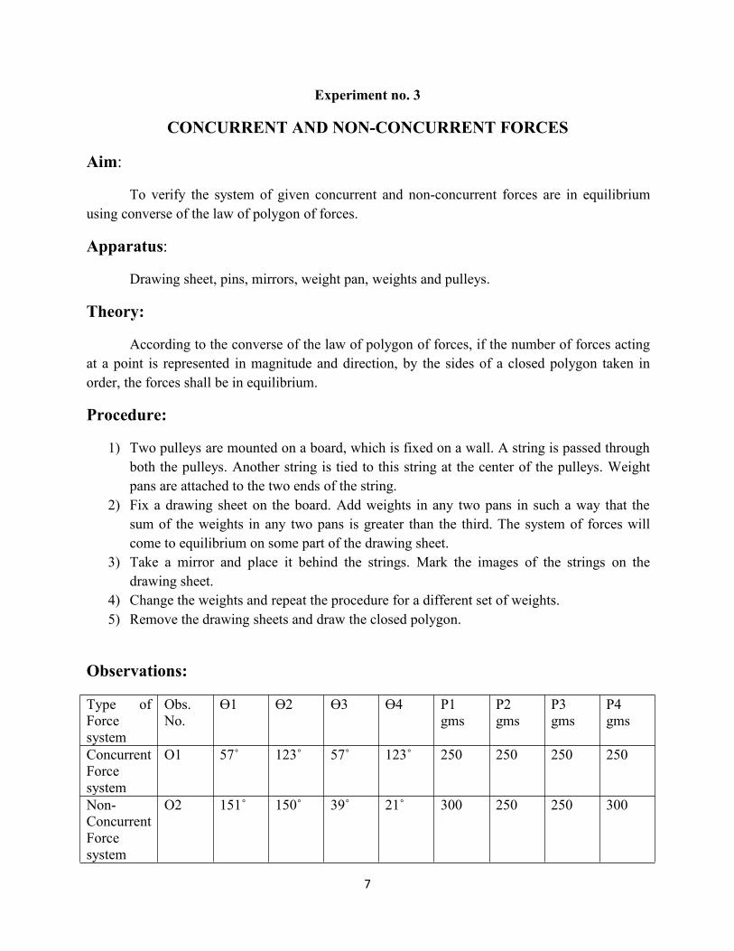
Observations:
Type ofForcesystem
Obs.No.
Ɵ1 Ɵ2 Ɵ3 Ɵ4 P1gms
P2gms
P3gms
P4gms
ConcurrentForcesystem
O1 57˚ 123˚ 57˚ 123˚ 250 250 250 250
Non-ConcurrentForcesystem
O2 151˚ 150˚ 39˚ 21˚ 300 250 250 300
8
9
Result:
10
Experiment No. 4
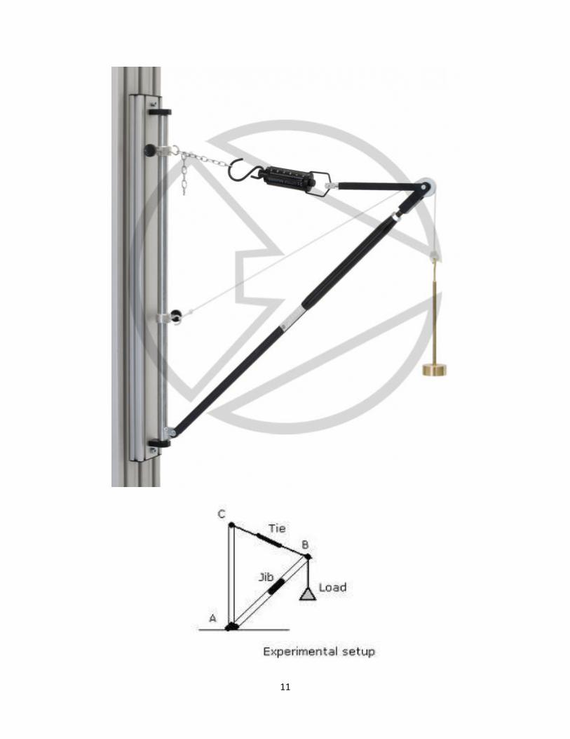
JIB CRANE
Aim:
To find out forces in the jib member and tie member of the jib crane experimentally andverify it analytically and graphically.
Apparatus:
Jib crane, load hanger, weights and measuring tape.
Theory:
The jib crane is an example of three concurrent forces. The forces in the tie and the jibcan be calculated experimentally. Analytically it can be found by making use of Lami’s theorem,which states that when three forces acting on a body are in equilibrium, then each force isproportional to the sine of the angle between the other two forces.
Procedure:
1) Note the initial reading in the spring balance at the tie member and spring support at thejib.
2) Suspend a known weight in the hanger at the apex.3) Note the final readings in the spring balance and spring support.4) Determine the effective forces in the jib and tie. (Final reading – initial reading)5) Repeat the procedure for different values of the suspended weight.6) Forces in the jib and tie members are found analytically using Lami’s theorem.7) Forces in the jib and tie members are found graphically by drawing the space vector
diagram.
Observation table:
LoadAtapex(kg)
Spring support Experimentally(kg)
Analytically(kg)Final Initial
Jib Tie Jib Tie Jib Tie Jib Tie
11

12
Result:
13
Experiment No. 5
COEFFICIENT OF FRICTION
Aim:
To determine the co-efficient of friction between wood and glass.
Apparatus:
Glass pane, wooden block, pulleys and weights.
Theory:
When one body moves, or tends to move tangentially over the surface of the other, itexperiences a force which opposes the motion. This force acting opposite to the direction ofmotion is called friction.
a) Angle of friction: The normal reaction and the frictional force can be combined into onesingle resultant force. The angle which this resultant makes with the normal reaction iscalled angle of friction. It in denoted by Φ.
tan� � µ
Where µ is co-efficient of friction.
b) Co-efficient of friction (µ) : It is the ratio of limiting frictional force to the normalreaction.µ = �
�
where F is the frictional force
N is the normal reaction
Procedure:
1) Set the plane horizontally either with the help of a spirit level or by making theinclination of the plane 0º.
2) Take a string with a pan attached to it and pass the string over the pulley fixed to theplane in such a way that the string is parallel to the plane.
3) Attached to the other end of the string, is a wooden block kept on the plane.4) Place the weights in the pan and record the weights in the pan. Record the weight at
which the wooden block is about to move.5) Repeat the procedure by placing different weights on the wooden block for two more
readings.
14
Observation table:
WeightOf blockW1 (gms)
WeightOn blockW2 (gms)
TotalWeight
W=W1+W2(gms)
Weight ofPan
P1 (gms)
Weight inPan
P2 (gms)
TotalEffort
P=P1+P2(gms)
µ= ��
50 200 250 31 20 51 0.2
Result:
15
Experiment No. 6
BEAM REACTIONS
Aim:
To determine the reactions of the beam experimentally and analytically for the followingcases of beam:
i) Simply supported at both ends.ii) Simply supported with an overhang on one side.iii) Simply supported with an overhang on both sides.
Apparatus:
A beam with spring support, a load hanger, weights and measuring tape.
Theory:
A beam is a structural element which has one dimension (length) considerably larger thanthe other two dimensions in the cross-section and is supported at few points. It is subjected tolateral loads. Due to applied loads, reactions develop at supports and the system of forcesconsisting of applied loads, self weight and reactions keep the beam in equilibrium. The forcesconstitute a system of coplanar non-concurrent system in equilibrium. Thus if a body is inequilibrium, then the conditions of equilibrium to be followed are as follows:
i) ΣH = 0ii) ΣV = 0iii) ΣM = 0
Procedure:
1) Measure the span of the beam which is the centre to centre distance between the springsupports.
2) Note the initial readings on both the spring supports.3) Add some weight on the load hanger which may be placed at any point in the span of the
beam and note down the distances of the load from the supports.4) Also note down the readings of the spring balance. The first reading will give the
experimental value of the support reaction.5) Change the position of the beam support such that the beam is overhanging on one side
and thereafter repeat the procedure after making the beam overhanging on both sides.
16
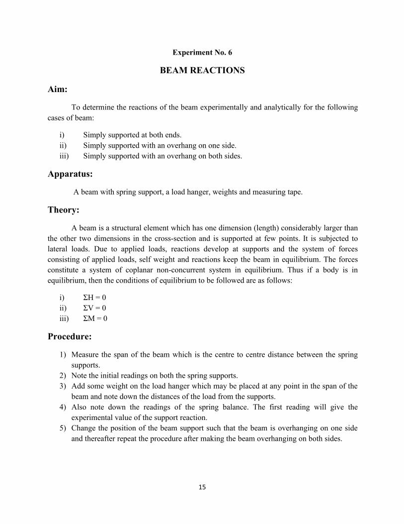
Beam simply supported at both ends
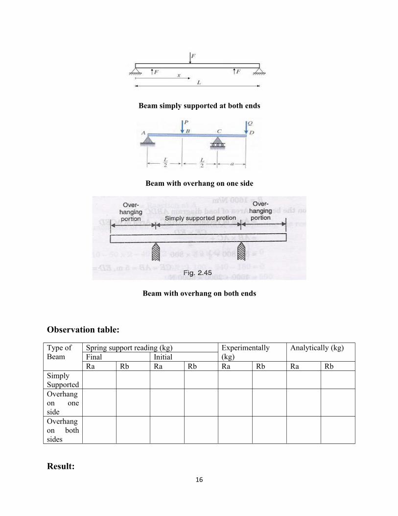
Beam with overhang on one side
Beam with overhang on both ends
Observation table:
Type ofBeam
Spring support reading (kg) Experimentally(kg)
Analytically (kg)Final InitialRa Rb Ra Rb Ra Rb Ra Rb
SimplySupportedOverhangon onesideOverhangon bothsides
Result: